US8971846B2 - Method and apparatus for translation and authentication for a virtual operator of a communication system - Google Patents
Method and apparatus for translation and authentication for a virtual operator of a communication system Download PDFInfo
- Publication number
- US8971846B2 US8971846B2 US11/669,140 US66914007A US8971846B2 US 8971846 B2 US8971846 B2 US 8971846B2 US 66914007 A US66914007 A US 66914007A US 8971846 B2 US8971846 B2 US 8971846B2
- Authority
- US
- United States
- Prior art keywords
- subscriber
- serving network
- network
- service
- request packet
- Prior art date
- Legal status (The legal status is an assumption and is not a legal conclusion. Google has not performed a legal analysis and makes no representation as to the accuracy of the status listed.)
- Expired - Fee Related, expires
Links
Images


Classifications
-
- H—ELECTRICITY
- H04—ELECTRIC COMMUNICATION TECHNIQUE
- H04W—WIRELESS COMMUNICATION NETWORKS
- H04W12/00—Security arrangements; Authentication; Protecting privacy or anonymity
- H04W12/08—Access security
-
- H—ELECTRICITY
- H04—ELECTRIC COMMUNICATION TECHNIQUE
- H04L—TRANSMISSION OF DIGITAL INFORMATION, e.g. TELEGRAPHIC COMMUNICATION
- H04L12/00—Data switching networks
- H04L12/02—Details
- H04L12/14—Charging, metering or billing arrangements for data wireline or wireless communications
-
- H—ELECTRICITY
- H04—ELECTRIC COMMUNICATION TECHNIQUE
- H04L—TRANSMISSION OF DIGITAL INFORMATION, e.g. TELEGRAPHIC COMMUNICATION
- H04L12/00—Data switching networks
- H04L12/02—Details
- H04L12/14—Charging, metering or billing arrangements for data wireline or wireless communications
- H04L12/1403—Architecture for metering, charging or billing
-
- H—ELECTRICITY
- H04—ELECTRIC COMMUNICATION TECHNIQUE
- H04L—TRANSMISSION OF DIGITAL INFORMATION, e.g. TELEGRAPHIC COMMUNICATION
- H04L12/00—Data switching networks
- H04L12/02—Details
- H04L12/14—Charging, metering or billing arrangements for data wireline or wireless communications
- H04L12/1442—Charging, metering or billing arrangements for data wireline or wireless communications at network operator level
- H04L12/145—Charging, metering or billing arrangements for data wireline or wireless communications at network operator level trading network capacity or selecting route based on tariff
-
- H04L29/12905—
-
- H—ELECTRICITY
- H04—ELECTRIC COMMUNICATION TECHNIQUE
- H04L—TRANSMISSION OF DIGITAL INFORMATION, e.g. TELEGRAPHIC COMMUNICATION
- H04L61/00—Network arrangements, protocols or services for addressing or naming
- H04L61/09—Mapping addresses
- H04L61/10—Mapping addresses of different types
- H04L61/106—Mapping addresses of different types across networks, e.g. mapping telephone numbers to data network addresses
-
- H04L61/6054—
-
- H—ELECTRICITY
- H04—ELECTRIC COMMUNICATION TECHNIQUE
- H04L—TRANSMISSION OF DIGITAL INFORMATION, e.g. TELEGRAPHIC COMMUNICATION
- H04L69/00—Network arrangements, protocols or services independent of the application payload and not provided for in the other groups of this subclass
- H04L69/08—Protocols for interworking; Protocol conversion
-
- H—ELECTRICITY
- H04—ELECTRIC COMMUNICATION TECHNIQUE
- H04W—WIRELESS COMMUNICATION NETWORKS
- H04W12/00—Security arrangements; Authentication; Protecting privacy or anonymity
- H04W12/06—Authentication
-
- H—ELECTRICITY
- H04—ELECTRIC COMMUNICATION TECHNIQUE
- H04L—TRANSMISSION OF DIGITAL INFORMATION, e.g. TELEGRAPHIC COMMUNICATION
- H04L2101/00—Indexing scheme associated with group H04L61/00
- H04L2101/60—Types of network addresses
- H04L2101/618—Details of network addresses
- H04L2101/654—International mobile subscriber identity [IMSI] numbers
-
- H—ELECTRICITY
- H04—ELECTRIC COMMUNICATION TECHNIQUE
- H04L—TRANSMISSION OF DIGITAL INFORMATION, e.g. TELEGRAPHIC COMMUNICATION
- H04L63/00—Network architectures or network communication protocols for network security
- H04L63/08—Network architectures or network communication protocols for network security for authentication of entities
-
- H—ELECTRICITY
- H04—ELECTRIC COMMUNICATION TECHNIQUE
- H04W—WIRELESS COMMUNICATION NETWORKS
- H04W12/00—Security arrangements; Authentication; Protecting privacy or anonymity
- H04W12/60—Context-dependent security
- H04W12/69—Identity-dependent
- H04W12/72—Subscriber identity
-
- H04W76/02—
-
- H—ELECTRICITY
- H04—ELECTRIC COMMUNICATION TECHNIQUE
- H04W—WIRELESS COMMUNICATION NETWORKS
- H04W76/00—Connection management
- H04W76/10—Connection setup
-
- H—ELECTRICITY
- H04—ELECTRIC COMMUNICATION TECHNIQUE
- H04W—WIRELESS COMMUNICATION NETWORKS
- H04W8/00—Network data management
- H04W8/26—Network addressing or numbering for mobility support
Definitions
- MNO Mobile Network Operator
- MVNO Mobile Virtual Network Operator
- MNOs are the parties who own the communication infrastructure.
- MNOs rent their infrastructure to the MVNOs.
- MNOs include Verizon, Sprint and T-Mobile.
- An example of an MVNO is the Virgin Mobile operator.
- the MVNO launches services based on the rented infrastructure from the MNO and the MVNO's contracts for the services with the MNO.
- the subscribers of the MVNO are provided with identifiers that the MNO provides to the MVNO.
- the MVNO may be practically limited to the existing MNO since the change requires mass notification and replacement of the identifiers provided to the existing subscribers. Changing the identifiers for the existing subscribers may not be feasible because an MVNO may have over one million subscribers.
- the MVNO may be limited to the services the particular MNO provides based on their agreement with the MNO. An example of the difficulties of moving between MNOs is illustrated in the following paragraphs.
- the MVNO manufactures one million subscriber identity module (SIM) cards for their subscribers.
- SIM subscriber identity module
- the MVNO now needs to have a partnership with an MNO since the MNO is the operator of the radio towers.
- the MVNO negotiates with an MNO and receives one million identifiers from the MNO, which are provided to the MVNO's subscribers.
- the MVNO decides that using the current MNO is too expensive.
- the MVNO negotiates with another MNO for one million identifiers.
- a method comprises:
- a method comprises:
- a method comprises:
- an apparatus comprises:
- an apparatus comprises:
- an apparatus comprises:
- an apparatus comprises:
- a device configured to receive, from a first mobile operator, an identifier of hardware which requests to communicate;
- a device configured to determine, by referring to a database, whether the hardware is permitted to communicate to the first mobile operator
- a device configured to indicate to the first mobile operator that the hardware is to communicate using the first mobile operator
- a device configured to change a database indicating the hardware is to use a second mobile operator
- a device configured to receive, from a second mobile operator, the identifier of the hardware which requests to communicate.
- an apparatus comprises:
- a device configured to receive, from a first mobile operator, an identifier of hardware which requests to be authenticated;
- a device configured to determine, by referring to a database, whether the first mobile operator hardware is permitted to authenticate the hardware
- a device configured to indicate to the first mobile operator that the first mobile operator is to authenticate the hardware
- a device configured to change a database indicating that a second mobile operator authenticates the hardware.
- an apparatus comprises:
- a device configured to receive, from a first mobile operator, an identifier of a requested service
- a device configured to determine, by referring to a database, a plurality of mobile operators that provide the requested service
- a device configured to select, from the plurality of mobile operators, at least one mobile operator for providing the requested service using network optimization criteria.
- FIG. 1A illustrates a two component network architecture
- FIG. 1B illustrates a multi-tier network architecture
- FIG. 1C illustrates a virtual operator multi-tier network architecture
- FIG. 2 illustrates a network configuration for serving networks in the virtual operator
- FIG. 3A illustrates an example IP network
- FIG. 3B illustrates an example wireless network
- FIG. 4 illustrates the architecture for a virtual operator
- FIG. 5 illustrates the network configuration before subscriber provisioning
- FIG. 6 illustrates in Table 1 an example serving network offerings to MVNO
- FIG. 7 illustrates in Table 2 key identifiers provisioned for the subscribers
- FIG. 8 illustrates in Table 3 subscriber profiles with the key identifiers
- FIG. 9 illustrates in Table 4 the assigned serving networks for each subscriber
- FIG. 10 illustrates in Table 5 an example format of the subscriber profile data
- FIGS. 11A and 11B illustrate an exemplary method for provisioning subscribers
- FIG. 12 illustrates the network configuration after the subscriber provisioning method is performed
- FIG. 13 illustrates in Table 6 the serving networks mapped to the services offerings
- FIG. 14 illustrates in Table 7 the service offerings from the various serving networks and the services desired by the subscribers
- FIG. 15 illustrates in Table 8 the services desired by each subscriber and the serving network providing the service
- FIG. 16 illustrates in Table 9 the serving networks the subscribers are attached to, the subscriber key identifiers, the service desired by each subscriber, and the serving networks providing the service desired;
- FIG. 17 illustrates in Table 10 an example services profile data
- FIG. 18 illustrates an exemplary method for provisioning services
- FIG. 19 illustrates the network configuration after subscriber provisioning and services provisioning are performed
- FIG. 20 illustrates in Table 11 an example translation table
- FIG. 21 illustrates in Table 12 an example translation table for GSM to CDMA conversion
- FIG. 22B illustrates in Table 14 an example IP packet
- FIG. 22C illustrates in Table 15 an example CDMA packet
- FIG. 23 illustrates in Table 16 an example translation table for key identifiers
- FIG. 24 illustrates in Table 17 the relationship between the old and new serving networks when subscribers are transferred
- FIG. 25 illustrates in Table 18 the serving network a subscriber is assigned to and the subscriber's subscriber key identifier
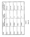
- FIG. 26A illustrates in Table 19A an example service request packet
- FIG. 26B illustrates in Table 19B example service center numbers
- FIG. 26C illustrates in Table 19C example service types
- FIG. 27A illustrates in Table 20A an example authentication request packet
- FIG. 27B illustrates in Table 20B an example translated authentication request packet
- FIG. 27C illustrates in Table 20C an example service result
- FIG. 28B illustrates in Table 21B a translated service request packet for text messaging
- FIG. 28C illustrates in Table 21C an example service result for text messaging
- FIGS. 29A and 29B illustrate an exemplary method for servicing an authentication request
- FIG. 30 illustrates an example network configuration that handles an authentication request
- FIGS. 31A and 31B illustrate an exemplary method for handling a service request
- FIG. 32 illustrates an exemplary method for optimizing the selection of a serving network
- FIG. 33 illustrates an example network configuration for handling a service request
- FIG. 35 illustrates in Table 22 the types of Charge Detail Record (CDR) formats each serving network supports;
- CDR Charge Detail Record
- FIG. 36 illustrates in Table 33 the format of an example CDR
- FIG. 37 illustrates an exemplary method for sending CDRs to a virtual operator
- FIG. 38 illustrates in Table 34 the bandwidth allotment for each serving network
- FIG. 39 illustrates in Table 25 an example utilization rate plan that a MVNO has with a MNO
- FIG. 40 illustrates in Table 26 an example current utilization in rate file
- FIG. 41 illustrates in Table 27 an example subscriber account
- FIG. 42 illustrates an exemplary method for receiving and processing a CDR
- FIG. 43 illustrates in Table 28 an MVNO's rate plans with the MNOs
- FIG. 44 illustrates in Table 29 an example format of an Interconnect Charge Detail Record (IC-CDR);
- FIG. 45 illustrates an exemplary method for generating an IC-CDR
- FIG. 46 illustrates in Table 30 an example subscriber rating plan
- FIG. 47 illustrates in Table 31 an example rate plan an MVNO has with a subscriber
- FIG. 48 illustrates in Table 32 an example format of a Subscriber Charge Detail Record (sub-CDR);
- FIG. 49 illustrates an exemplary method for generating a sub-CDR
- FIG. 50 illustrates in Table 33 the format of an example profitability analysis report
- FIG. 51 illustrates an exemplary method for generating a profitability analysis report
- FIG. 52 illustrates a third embodiment of the virtual operator
- FIG. 53 illustrates multiple virtual multiple operators, corresponding to the third embodiment, connected together
- FIG. 54 illustrates in Table 34 an example translation table for a multiple virtual operator system
- FIG. 55 illustrates an example network deployment of the third embodiment of the virtual operator.
- a MVNO may be the party that owns and operates a virtual operator (VO).
- a MNO may be the operator of a serving network (SNW), which the virtual operator may use to receive a service from.
- SNW serving network
- a virtual operator can provide services to subscribers across networks of different technology types. Additionally, a subscriber can be moved from one serving network to another serving network for the services while the virtual operator keeps track of the subscribers' identifiers. Examples of services include subscriber authentication, Internet access, text messaging, e-mail, making a voice call, etc.
- FIG. 1A illustrates a two-tier network architecture.
- the network architecture in FIG. 1A contains a graphical user interface (GUI) 2 a , a network logic/service logic unit 4 a , a transaction logic/business logic unit 6 a , and a database 8 a .
- the GUI user interface is any computer terminal that preferably provides a visual interface with the user to access the network.
- the network logic/service logic 4 a contains the middleware used to transfer data through the network. For example, for an IP network, the network logic/service logic 4 a contains routers, hubs, and switches.
- the transaction logic/business logic 6 a contains the decision tables necessary for routing data to the various elements in the network.
- the database 8 a is used to store routing information and subscriber information.
- FIG. 1B illustrates a multi-tier network architecture containing a thin client user interface 2 b , network logic 4 b , service logic 6 b , transaction logic 8 b , and a database 10 b .
- the thin client user interface 2 b is similar to the GUI 2 a in FIG. 1A .
- the network logic 4 b and the service logic 6 b perform the same functionality as the network logic/service logic 4 a of FIG. 1A .
- the difference between the network logic 4 b and the service logic 6 b and their counterpart in FIG. 1A is that the functionalities are separated into separate units.
- the transaction logic 8 b performs the same functionality as the transaction logic/business logic 6 a in FIG. 1A .
- the database 10 b performs the same functionality as the database 8 a of FIG. 1A .
- FIG. 1C illustrates an exemplary embodiment of the virtual operator implemented on a network architecture.
- the administration layer 2 c performs the function of provisioning subscriber data and the data related to particular serving networks. This data may include the identity of the subscribers, and the particular services that each serving network provides.
- the services logic layer 4 c performs the function of mapping services to each serving network.
- the network elements 6 c is used to store information relating to the components of each serving network.
- the business elements 8 c is used to store information relating to the contracts MVNO has with each serving network.
- the network interfacing layer 10 c provides the hardware and logic necessary to interface with each serving network.
- the intra platform communication framework 12 c provides the hardware and logic for communication with the different types of serving networks.
- the database 14 c is used to store information such as subscriber data, the services provided by each serving network, and particular rate plans provided by the serving networks.
- FIG. 2 illustrates a relationship between the subscribers, the serving networks, and the virtual operator. Each subscriber is designated as “SB#”. Each serving network is designated as “SNW#”.
- FIG. 2 illustrates four subscribers SB 1 , SB 2 , SB 3 , and SB 4 . Subscribers communicate with their serving networks through a any desired device such as a computer terminal, a mobile phone, a Personal Device Assistant (PDA), etc. How a subscriber communicates with a serving network may be dependent on the technology requirements of the serving network.
- FIG. 2 illustrates four serving networks SNW 1 , SNW 2 , SNW 3 , and SNW 4 .
- a serving network can be any desired network architecture types such as a Global System For Mobile Communications (GSM) network, an Internet (IP) network, a Code Division Multiple Access (CDMA), etc.
- GSM Global System For Mobile Communications
- IP Internet
- CDMA Code Division Multiple Access
- each subscriber may be provisioned to a particular serving network.
- FIG. 2 illustrates subscriber SB 1 provisioned to serving network SNW 1 , subscriber SB 2 provisioned to serving network SNW 2 , subscriber SB 3 provisioned to serving network SNW 3 , and subscriber SB 4 provisioned to serving network SNW 4 .
- each of the serving networks SNW 1 to SNW 4 communicates to a virtual operator (VO) 100 through a network interface gateway 16 .
- the network interface gateway 16 allows the virtual operator 100 to communicate with varying networks such as a GSM, CDMA, or an IP network, all under the same framework.
- the network interface gateway 16 may incorporate any desired signaling protocol to transmit data. These signaling protocols include, but are not limited to, Signaling System 7 (SS7) or C-7 signaling.
- SS7 Signaling System 7
- the standard interfaces the network interface gateway 16 may support includes Integrated Services User Part (ISUP), Customized Applications Mobile Enhanced Logic (CAMEL), Wireless Intelligent Network (WIN), Remote Authentication Dial-In User Service (RADIUS), DIAMETER (an upgrade for RADIUS), etc.
- ISUP Integrated Services User Part
- CAMEL Customized Applications Mobile Enhanced Logic
- WIN Wireless Intelligent Network
- RADIUS Remote Authentication Dial-In User Service
- DIAMETER an upgrade for RADIUS
- the network interface gateway 16 is not limited to these interfaces and may support any desired interface.
- the connections between each serving network SNW 1 to SNW 4 to the network interface gateway 16 , and the virtual operator 100 to the network interface gateway 16 is bidirectional. For example, data may pass in both directions from each serving network SNW 1 to SNW 4 to network interface gateway 16 to the virtual operator 100 , and vice versa.
- FIGS. 3A and 3B illustrate exemplary embodiments of particular types of serving networks.
- FIG. 3A illustrates a standard IP network 20 .
- the IP network 20 contains computer terminals (CPU) 22 a , 22 b , 22 c and 22 d .
- CPU 22 a , 22 b , 22 c , and 22 d communicate with a switch 24 that communicates with gateway 26 .
- the gateway 26 provides connectivity to any other IP network.
- FIG. 3B illustrates a standard wireless network 30 .
- the wireless network contains cell towers 32 a , 32 b , 32 c , and 32 d , which are connected to base station controllers 34 a and 34 b .
- Each base station controller is connected to a radio network controller 36 .
- the radio network controller 36 controls handover from base station controller 34 a to base station controller 34 b.
- FIG. 4 illustrates an exemplary architectural embodiment of the virtual operator 100 .
- a subscriber provisioning layer 104 includes the functionalities of assigning an identifier from a serving network to a subscriber.
- the services provisioning layer 106 includes the functionality of mapping the services each serving network provides.
- the authorization layer 108 includes the functionality of identifying a subscriber, authenticating a subscriber, and providing services for a subscriber between heterogeneous networks.
- the billing and rating layer 110 includes the functionality of calculating bills for a subscriber's use of a service, and providing real-time rates for connecting to a serving network.
- the billing functionality from the billing and rating layer 110 includes both real time and non real time billing for the services.
- the interconnect and settlement layer 112 includes control-logic for routing messages between the different serving networks. The functionalities of each layer will be described in more detail in the following figures. While the term “layer” has been used throughout this writing, each of these layers and other aspects of the invention can be treated as a block which may be implemented using a programmed general purpose computer a special purpose device using ASICs or other special purpose hardware, or a combination of general and special purpose hardware.
- the subscriber provisioning layer 104 , services provisioning layer 106 , authorization layer 108 , billing and rating layer 110 , an interconnect and settlement layer 112 are implemented in a variety of embodiments.
- each of the above-described layers are independently implemented on a server connected to each other through any desired network type 120 a and 120 b .
- connections 120 a and 120 b can be an IP network connecting each of the layers to each other.
- each of the above-described layers are implemented on a single server.
- the processing unit that each layer is implemented on such as a server can include any desired operating system, such as Linux.
- the communication protocols unit 122 is configured to implement the protocols used to communicate with each serving network through the network interface gateway 16 of FIG. 2 . These protocols may include, but are not limited to, the GSM, CDMA, IP, or Wi-Fi protocol, or any other desired protocol.
- the communication protocols unit 122 interfaces with the layers 104 to 12 through interface 120 a , which can be any desired network type such as an IP network.
- the operation and maintenance unit 114 is any computer or terminal allowing a user of the virtual operator to access the layers.
- the operation and maintenance unit contains a Graphical User Interface (GUI) so that the user can perform maintenance operations on the layers. Maintenance operations may include, but are not limited to, upgrading software on each of the layers.
- GUI Graphical User Interface
- Maintenance operations may include, but are not limited to, upgrading software on each of the layers.
- the operation and maintenance unit 114 interfaces with each of the layers through interface 120 b .
- the interface 120 b is any desired network type such as an IP network.
- the database 116 includes the functionality of storing data necessary to carry out the operations of the virtual operator. Such data includes, but is not limited to, subscriber data or the service offerings from each SNW. Each of the layers 104 through 112 can retrieve data from the database 116 or store data in the database 116 as necessary.
- the business logic unit includes the functionality of providing the layers 104 through 112 of virtual operator 100 with information regarding the MVNO's contracts with the MNOs.
- the business logic unit 118 provides the layers 104 through 112 with the prices an MNO charges for services.
- the business logic unit 118 communicates with the layers 104 through 112 through interface 120 b.
- the subscriber provisioning layer 104 and the services provisioning layer 106 are designated as the customer care layers indicating that these layers define the subscribers' relationships with the MVNO.
- the subscriber provisioning layer 104 includes the functionality of provisioning, i.e. assigning, subscribers to the respective serving networks.
- assigning a subscriber to a serving network includes the step of assigning the subscriber with a Subscriber Key identifier, and updating the subscriber's Virtual Key identifier.
- a Subscriber Key identifier is an identifier a subscriber may use to log onto a serving network.
- a Virtual Key identifier is an identifier the virtual operator 100 uses to determine which serving network authenticates the subscriber. The assigning and updated of identifiers will be explained in more detail in the following paragraphs.
- FIG. 5 illustrates the configuration of the serving networks before the subscriber provisioning layer 104 of FIG. 4 performs subscriber provisioning.
- serving networks SNW 1 , SNW 2 , SNW 3 , SNW 4 , and SNW 5 communicate to the virtual operator 100 through the network interface gateway 16 in the same manner as described in FIG. 2 .
- FIG. 5 illustrates subscribers SB 1 , SB 2 , SB 3 , SB 4 , SB 5 , and SB 6 , where each subscriber has not been assigned to any of the serving networks SNW 1 to SNW 5 . Therefore, subscribers SB 1 to SB 6 have not been assigned Subscriber Key identifiers necessary for providing network access to the subscribers.
- an MVNO may need to contract for the identifiers from the MNOs of serving networks SNW 1 to SNW 5 .
- Table 1 of FIG. 6 illustrates the serving network offerings of serving networks SNW 1 to SNW 5 to the MVNO.
- the Price Offered per Subscriber in Table 1 illustrates the prices that each respective serving network offers per subscriber identifier.
- the Subscriber Identifier for the technology of the SNW indicates the different types of subscriber identifiers.
- the different types of subscriber identifiers include, but are not limited to, an International Mobile Subscriber Identity (IMSI), a Mobile Identification Number (MIN), a user ID/password, or any other desired identifier.
- IMSI International Mobile Subscriber Identity
- MIN Mobile Identification Number
- user ID/password or any other desired identifier.
- the identifiers are used for identifying the hardware a subscriber is using such as a the subscriber's Subscriber Identity Module (SIM) card. In another embodiment, the identifiers can be used to identify the subscriber.
- SIM Subscriber Identity Module
- the Number of Subscribers indicates the number of subscribers that can be assigned an identifier for a respective serving network.
- the Network Address is used to identify a unique address for each of the serving networks.
- the Type of the Network illustrates the different types of networks that a virtual operator may communicate with such as a GSM, CDMA, or IP network.
- serving network SNW 1 is a GSM network with a network address GT:101.
- Serving network SNW 1 is offering a price per a subscriber identifier at price P 1 .
- the type of identifiers serving network SNW 1 offers are IMSI identifiers ranging from IMSI# 0 to IMSI# 10 .
- serving network SNW 1 is allowing the MVNO to assign up to 10,000 subscribers to serving network SNW 1 .
- the virtual operator 100 may assign a Virtual Key identifier to the subscriber that matches the subscriber's Subscriber Key Identifier.
- Table 2 of FIG. 7 illustrates the Subscriber Key identifiers and Virtual Key identifiers for subscribers SB 1 to SB 6 . In Table 2, each of the subscribers' Virtual Key identifiers matches their Subscriber Key Identifiers. Table 2 may represent the scenario where subscribers SB 1 to SB 6 have entered into contracts and have been assigned identifiers for the first time.
- the subscriber may receive a Subscriber Key identifier IMSI # 1 . Since this is the first time the subscriber is receiving a Subscriber Key identifier, the Virtual Key identifier is set to match the Subscriber Key identifier IMSI# 1 . If the MVNO needs to move Subscriber SB 1 to another serving network, the use of Virtual Key identifier allows the MVNO to change the Virtual Key identifier of Subscriber SB 1 while subscriber SB 1 keeps his or her original Subscriber Key identifier to log onto the network.
- the MVNO assigns general identifiers to its subscribers while the subscribers' Virtual Key identifiers are matched to the identifiers of the serving networks. For example, when subscriber SB 1 enters into a contract with the MVNO, subscriber SB 1 may be assigned a Subscriber Key identifier MVNO_Identifier# 1 whereas the subscriber SB 1 's Virtual Key identifier is set to IMSI# 1 .
- Table 1 of FIG. 6 and Table 2 of FIG. 7 can be stored in any memory device located on the virtual operator 100 such as database 116 of FIG. 4 .
- the subscriber provisioning layer 104 of FIG. 4 is configured to retrieve the information contained in Table 1 and Table 2 when necessary.
- Table 3 of FIG. 8 illustrates the relationship between the subscribers with their respective Subscriber Key identifiers and the service access equipment required.
- the Type of service access equipment in column 3 of Table 3 illustrates the service access equipment each subscriber uses for their respective Subscriber Key identifiers.
- Table 3 of FIG. 8 illustrates that subscriber SB 1 has been assigned a Subscriber Key identifier of IMSI # 1 , which uses access equipment for a GSM network.
- Table 4 of FIG. 9 illustrates the relationship between subscribers SB 1 to SB 6 and serving networks SNW 1 to SNW 5 .
- Table 3 of the FIG. 8 illustrates that subscriber SB 3 received a Subscriber Key identifier of MIN # 33 .
- Table 1 of FIG. 6 illustrates that the identifier MIN # 33 corresponds to serving network SNW 3 . Therefore, as shown in Table 4 of FIG. 9 subscriber SB 3 is attached to serving network 3 .
- the virtual operator 100 can refer to a subscriber's profile data.
- Table 5 of FIG. 10 illustrates the subscriber profile data the VO uses to assign a subscriber a Subscriber Key identifier, thus attaching a subscriber to a serving network.
- subscriber SB 3 may contract with an MVNO for services S 3 and S 4 .
- the subscriber lets the MVNO know that its technology requirements are for a CDMA network.
- the subscriber may contract for using services S 3 and S 4 at a fixed rate, which means that subscriber SB 3 may use these services at a fixed price.
- Table 5 of FIG. 10 illustrates the exemplary embodiment of subscriber profile data.
- the subscriber profile data may include other factors such as a subscriber's geographic location, and the expiration date of the subscribers contract with the MVNO.
- the MVNO may use the operation and maintenance unit 114 of FIG. 4 to enter the subscriber profile data, which may be stored in database 116 of FIG. 4 .
- FIGS. 11A and 11B illustrate an exemplary method the virtual operator 100 or other entity performs in assigning a subscriber a Subscriber Key identifier and updating the Virtual Key identifier.
- the method illustrated in FIGS. 11A and 11B can be performed in the Subscriber Provisioning layer 104 of FIG. 4 . While the method illustrated in FIGS. 11A and 11B is an exemplary embodiment, other methods may be used to assign a Subscriber Key identifier to a subscriber in updating the virtual key identifier.
- Step 200 of FIG. 11A starts the subscriber provisioning process by reading subscriber's profile data.
- the virtual operator reads the subscriber's profile data illustrated in Table 5 of FIG. 10 from database 116 of FIG. 4 .
- step 202 determines the subscriber's rate plan from the profile data.
- step 204 determines the serving networks that meet the subscriber's technology requirements.
- the virtual operator uses the retrieved subscriber profile data to determine the technology requirements of the subscriber.
- Table 5 of FIG. 10 illustrates that subscriber SB 3 uses a CDMA network.
- the virtual operator uses the SNW offerings from Table 1 of FIG. 6 to determine that serving networks SNW 3 and SNW 5 are CDMA networks.
- the virtual operator retrieves the SNW offerings in Table 1 of FIG. 6 from the database 116 of FIG. 4 .
- Step 206 determines the networks that provide services that the subscriber desires.
- the virtual operator uses the subscriber profile data to determine the services that the subscriber desires.
- Table 5 of FIG. 10 illustrates that subscriber SB 3 desires services S 3 and S 4 .
- the virtual operator determines which networks provide which services from the services provisioning layer 106 of FIG. 4 , which will be described later in further detail.
- step 208 retrieves the prices for the services from the services provisioning layer 106 of FIG. 4 .
- step 210 determines the networks that meets the subscriber's rate plan.
- the virtual operator uses the retrieved subscriber profile data to determine the rate plan the subscriber uses, and comparing the rate plan with the prices that each serving network offers for the services.
- Table 5 of FIG. 10 illustrates that subscriber SB 3 desires services S 3 and S 4 at a fixed rate plan. Therefore, the virtual operator can determine the networks that provide these services at a fixed rate.
- step 210 flow proceeds to step 212 which determines if there is a serving network that meets the subscriber's requirements. If there is no serving network that meets the subscriber's requirement, flow proceeds to step 218 . Step 218 determines if there is another subscriber that needs to be provisioned. If there is not another subscriber that needs to be provisioned, the process of FIG. 11A ends. If there is another subscriber that needs a subscriber identifier, flow returns to step 200 and repeats the same process.
- step 212 determines that there is a serving network that meets the subscriber's requirements
- flow proceeds to step 214 which determines whether the network that meets the subscriber's requirements is fill. For example, Table 1 of FIG. 6 illustrates that 30,000 subscribers may be assigned identifiers to serving network SNW 3 . If 30,000 identifiers are already assigned to SNW 3 , then the network is full. If the network is full, flow proceeds to step 216 of FIG. 11A .
- step 216 determines there is another SNW that meets a subscriber's requirements, flow returns to step 214 .
- Table 5 of FIG. 10 illustrates that subscriber SB 3 uses a CDMA network.
- Table 1 of FIG. 6 illustrates that serving network SNW 3 and SNW 5 are both CDMA networks. If serving network SNW 3 is full, flow returns to step 214 to check to see if serving network SNW 5 is full. If serving network SNW 5 is not full, then flow proceeds from step 214 to process SBP_A of FIG. 11B . If there is not another SNW that meets the subscriber's requirements, flow proceeds from step 216 to step 218 and repeats the process described above for step 218 .
- step 224 flow proceeds to process SBP_B of FIG. 11A .
- Step 226 updates the subscriber's Virtual Key identifier to match the network to which the subscriber is assigned.
- flow proceeds to process SBP_B of FIG. 11A .
- Step 226 represents the situation where a subscriber is transferred from one serving network to another serving network.
- the virtual operator may assign the subscriber to serving network SNW 1 .
- the MVNO may have the virtual operator move the subscriber to serving network SNW 2 .
- the subscriber may keep the Subscriber Key identifier that was assigned to the subscriber, when the subscriber was first assigned serving network SNW 1 .
- the method of updating the Virtual Key identifier when a subscriber is transferred between serving networks provides the advantage of allowing the subscriber to keep the original Subscriber Key identifier.
- step 224 or step 226 flow proceeds to process SBP_B of FIG. 11A .
- Process SBP_B starts at step 218 of FIG. 11A .
- process SBP_B enters step 218 the process described above for step 218 is repeated.
- the Services Provisioning layer 106 of FIG. 4 is responsible for mapping the services that each serving network provides.
- Table 6 of FIG. 13 illustrates the serving networks, the services that the MNOs provide on their serving network, and the price of the service.
- the MNO of serving network SNW 1 offers service S 1 at price PS 11 and service S 2 at price PS 12 .
- the price of the service may be the price that the MVNO contracted for with the MNO.
- Subscribers may subscribe for more than one service. Therefore, the subscriber may be provided a service from a serving network different from the serving network the subscriber is currently using.
- Table 8 of FIG. 15 illustrates the Service Desired for each subscriber, and the Serving Network providing the service to the subscriber.
- subscriber SB 3 desires service S 3 and service S 4 .
- Table 6 of FIG. 13 shows that serving networks SNW 3 and SNW 4 both provide service S 3 .
- An example of services include call setup, text messaging content download. The method of choosing a serving network to provide a service when there is more than one serving network available, will be described in more detail when describing the functions of the Authorization layer 108 of FIG. 4 .
- the virtual operator internally keeps track of which serving networks provides which service.
- the virtual operator uses a file located on a memory device such as database 116 of FIG. 4 .
- the virtual operator uses the services profile illustrated in Table 10 of FIG. 17 to determine services provided by each serving network.
- FIG. 18 illustrates an exemplary method the virtual operator performs in the Services Provisioning layer 106 for provisioning the services.
- Step 300 retrieves the services profile.
- the services profile is located in database 116 of FIG. 4 .
- the services profile contains the same information as illustrated in Table 10 in FIG. 17 .
- Step 302 records the services provided by each serving network.
- Step 304 receives an Interconnect Charge Detail Record (IC-CDR) from the Interconnect and Settlement layer 112 of FIG. 4 .
- IC-CDR Interconnect Charge Detail Record
- the virtual operator performs the above-described process in the Services Provisioning layer 106 of FIG. 4 each time the serving network changes, or the service on the serving network changes.
- an MVNO may choose to stop using a particular serving network, because the cost of using that serving network is too high.
- an MNO may decide to stop providing the service or add a service to its serving network.
- the MVNO may contract with the MNO to allow the subscribers of the MVNO to use the MNOs newly provided service. Therefore, the process performed in the Services Provisioning layer 106 of the virtual operator 100 allows the subscribers of the MVNO to be independent of the services that each serving network provides.
- network interface gateway 16 serves the same function as discussed for network interface gateway 16 of FIG. 2 .
- the Authorization Layer 108 of FIG. 4 performs the functions of identification, translation, and authentication. Each of the functions will be described in more detail in the following paragraphs.
- the subscriber When a subscriber attempts to log onto a network, the subscriber uses his or her respective Subscriber Key identifier. As an example, all authentication requests, which contain the subscriber's identifier, are forwarded to the virtual operator. Table 3 of FIG. 8 illustrates each subscriber and his or her respective Subscriber Key identifier. The virtual operator compares the identifier in an authentication request to the Subscriber Key identifier listed in column 2 of Table 3. If the identifier of an authentication request matches the Subscriber Key identifier listed in column 2 of Table 3, then the subscriber is successfully identified by the virtual operator.
- the virtual operator performs translation for the technology and translation of the Virtual Key identifier for service delivery in the Authorization layer 108 .
- translation for the technology is performed when a serving network providing the requested service is using a network protocol different than the serving network the subscriber is using.
- the virtual operator is configured to transmit and receive messages to and from networks running any desired protocol, such as the GSM protocol, the CDMA protocol, or the IP protocol.
- a translation of network protocols is performed when a message is passed from a GSM network to a CDMA network. Additionally, since the GSM network uses an IMSI key identifier and a CDMA network uses an MIN key identifier, a translation of the identifiers is also performed.
- Another example of when translation of network protocols is performed is illustrated in the fifth row of Table 11. The fifth row illustrates the source network is a GSM network, which runs the GSM network protocol, while the destination network is an IP network using an IP protocol. Therefore, when a message passes from the source GSM network to the destination IP network, a translation of network protocols is performed.
- Table 11 of FIG. 20 also illustrates the serving networks offering the technology for the destination network.
- Subscriber SB 3 has a dual mode phone that works on a CDMA and a GSM network.
- the subscriber SB 3 is visiting a GSM network and turns on the phone while in the GSM network.
- an authentication request is forwarded to the virtual operator.
- the virtual operator identifies the subscriber using the information in Table 3 of FIG. 8 , and determines that the subscriber's authentication data is on serving network SNW 3 based on the information contained in Table 4 of FIG. 9 .
- Table 1 of FIG. 6 illustrates that serving network SNW 3 is a CDMA network.
- Tables 13, 14, and 15 illustrate that each packet format has a specified header format that is used for each of the packets' respective network protocol.
- the header information of the GSM packet as illustrated in Table 15 of FIG. 22A is converted to match the header information of an IP packet as illustrated in Table 14 of FIG. 22B for the destination IP network to be able to properly receive the data packet from the GSM network.
- the data field in the GSM packet of Table 13 is converted to match the data field of the IP packet illustrated in Table 14. Similar conversions are made if a GSM packet is converted to match a CDMA packet, or an IP packet is converted to match a CDMA packet.
- Any desired algorithm or software may be utilized to perform GSM to CDMA conversion, GSM to IP conversion, or IP to CDMA conversion. Examples of such algorithms or translation software may be found in U.S. Pat. No. 6,349,205 to Fang et al and U.S. Pat. No. 6,680,923 to Leon, the entire contents of both documents which are incorporated by reference.
- the virtual operator is configured to handle the signaling between the GSM network in an IP network, a GSM network and a CDMA network, or an IP network in a CDMA network.
- the Authorization layer 108 of FIG. 4 performs the translation as discussed above and uses the Communication Protocols unit 122 to forward the pack to a network interface gateway, which forwards the packet to the IP network.
- the virtual operator is configured to perform the translation of the Subscriber Key identifier to the Virtual Key identifier in the Authorization layer 108 .
- the Virtual Key identifier does not match the Subscriber Key identifier when the service provider for a subscriber changes.
- the subscriber's Virtual Key identifiers are updated to match the changed network.
- Table 16 of FIG. 23 illustrates the situation of when the MVNO transfers subscriber SB 3 from serving network SNW 3 to serving network SNW 1 .
- the Subscriber Key identifier is MIN # 33 corresponding to an identifier for serving network SNW 3 .
- subscriber SB 3 when subscriber SB 3 is transferred to serving network SNW 1 , subscriber SB 3 has a new identifier corresponding to serving network SNW 1 .
- subscriber SB 3 since subscriber SB 3 keeps the original subscriber key identifier MIN # 33 , only the Virtual Key identifier is updated. In one embodiment, updating the Virtual Key identifier is performed by the process described in FIGS. 11A and 11B .
- subscriber SB 3 continues to use Subscriber Key identifier MIN # 33 without seeing or having knowledge that the Virtual Key identifier has been updated.
- Table 16 of FIG. 23 illustrates that changing a Virtual Key identifier does not mean the serving network changed.
- subscriber SB 6 is provisioned a Subscriber key identifier User2@password. If the identifier User2@password were to become unavailable on serving network SNW 5 , the virtual operator updates subscriber SB 6 's Virtual Key identifier to a valid identifier, such as User3@password, on serving network SNW 5 through the process described in FIGS. 11A and 11B . Table 16 further illustrates that when the Virtual Key identifiers for both subscribers SB 3 and SB 6 are changed, the Subscriber Key identifiers for SB 3 and SB 6 remain the same.
- Table 17 of FIG. 24 illustrates the relationship between subscriber SB 3 's and SB 6 's old serving network to the new serving network.
- subscriber SB 3 's old serving network was SNW 3 .
- subscriber SB 3 was transferred to new serving network SNW 1 , reflected in the change to subscriber SB 3 's Virtual Key identifier.
- Table 17 illustrates that even though subscriber SB 6 's Virtual Key identifier changed, subscriber SB 6 did not change serving networks.
- the virtual operator continues to use the Subscriber Key identifier to identify the subscriber even though the Subscriber's Virtual Key identifier changed.
- the subscriber continues to use his or her Subscriber Key identifier when requesting authentication.
- Table 18 of FIG. 25 illustrates that when a subscriber is transferred to a new network, the subscriber maintains his or her Subscriber Key identifier. For example, when subscriber SB 3 was transferred to serving network SNW 1 , subscriber SB 3 kept the same Subscriber Key identifier MIN # 33 . Therefore, even though the Virtual Key identifier IMSI # 5 is used to authenticate subscriber SB 3 as illustrated in Table 16 of FIG. 23 , subscriber SB 3 still continues to use MIN # 33 to request authentication. Therefore, the Virtual Key identifier provides the advantage of allowing subscribers to keep their original Subscriber Key identifiers. By allowing subscribers to keep their subscriber key identifiers, the hardware that the subscribers use for authentication does not have to be changed.
- the virtual operator is configured to process all subscriber authentication requests in the Authorization layer 108 .
- the virtual operator is configured to handle authentication requests from varying types of networks, such as IP networks, GSM networks, and CDMA networks.
- IP networks such as IP networks, GSM networks, and CDMA networks.
- CDMA networks The format of an authentication request will be discussed later in more detail in FIGS. 26 a and 27 a.
- an MVNO may contract with an MNO to receive subscriber identifiers.
- a network element such as the serving switch is configured to recognize that the subscriber identifier was contracted for with a particular MVNO, and therefore forward the authentication request to that MVNO's virtual operator instead of forwarding the authentication request to the serving network's network authentication element such as a Home Location Register (HLR).
- HLR Home Location Register
- An HLR is a network authentication element containing a database of subscriber identifiers.
- the virtual operator When the virtual operator receives the authentication requests, the virtual operator identifies the subscriber based on information contained in Table 3 of FIG. 8 , and determines the serving network to perform authentication based on the information contained in Table 4 of FIG. 9 . After the virtual operator determines the serving network that performs authentication, the virtual operator forwards the authentication requests to that serving network's authentication element such as a Home Location Register (HLR) or Service Control Point.
- HLR Home Location Register
- Service Control Point Service Control Point
- the virtual operator contains a stand-alone database or an Authentication, Authorization, or Accounting (AAA) server running the Remote Authentication Dial In User Service (RADIUS) or DIAMETER (upgrade from RADIUS) protocols for performing authentication.
- AAA Authentication, Authorization, or Accounting
- RADIUS Remote Authentication Dial In User Service
- DIAMETER upgrade from RADIUS
- the virtual operator is configured to process the authentication request as a service request.
- Table 19A of FIG. 26A illustrates an exemplary embodiment of the format of the server's request packet.
- the service request packet contains field identifiers such as a Service Center Number, Service Type, Subscriber ID, and Subscriber Data.
- the Service Center Number field is used to indicate the network element that is to receive the requested service.
- the Service Type Field is used to indicate the type of service that is requested.
- the Subscriber ID field contains the identifier the subscriber uses when requesting authentication.
- the Subscriber Data Field holds the data used to perform the service.
- the service request packet illustrated in Table 19A is encoded in any format for a network running the GSM protocol, IP protocol, WIN protocol, or any other desired network protocol.
- Table 19B of FIG. 26B illustrates an exemplary embodiment of types of Service Center Numbers.
- a Service Center Number indicates the network element that receives the requested service or performs the requested service.
- Table 19B illustrates each serving network, and a serving network's network address as illustrated in column 5 of Table 1 in FIG. 6 .
- a serving network comprises a number of network elements.
- an IP network contains a number of switches, routers and hubs, with each network element having its own unique network address.
- the virtual operator is configured to hold information, such as in database 116 of FIG. 4 , indicating which network element in each serving network performs a service, or which network element in each serving network receives the result of a service request.
- An MNO provides the MVNO with this information, which the MVNO enters into the virtual operator.
- Table 19B of FIG. 26B lists only one network address as a Service Center Number for each serving network.
- a binary number represents a service center number, where a unique binary number represents each network element to perform a service or receive a service.
- the virtual operator is configured to translate the binary number to a network element of a serving network.
- Table 19C of FIG. 26C illustrates Service Types for a corresponding service.
- the Service Type field is represented by a binary number, and each service is represented by a unique binary number.
- Table 19C illustrates that the authentication service is represented by the binary number 00, a text messaging service is represented by the binary number 01, an e-mail service is represented by the binary number 10, and the voicemail service is represented by a binary number 11.
- the virtual operator is not limited to handling service requests for the services listed in Table 19C.
- the virtual operator updates the information in Table 19C to include the new service, and provide a unique binary identifier for the new service.
- Table 20B of FIG. 27B illustrates an exemplary embodiment of a translated service request packet. Since the service requested is for authentication, the virtual operator checks the Virtual Key identifier of the subscriber making the authentication request. The virtual operator verifies from Table 16 in FIG. 23 that the Virtual Key identifier for subscriber SB 3 is IMSI # 5 , and serving network SNW 1 performs the authentication. Using Table 19B of FIG. 26B , the virtual operator verifies that serving network SNW 1 's network address and Service Center Number is GT:101. Therefore, since serving network SNW 1 performs the authentication, Table 20B of FIG. 27B illustrates that the Service Center Number is changed to GT:101.
- Table 20B illustrates that the virtual operator updated the Subscriber ID field of the service to IMSI # 5 . After the virtual operator translates the service request packet as shown in Table 20B, the virtual operator forwards the service request packet to serving network SNW 1 .
- Table 20C of FIG. 27C illustrates an exemplary embodiment of a packet indicating the Service Result.
- the Service Result is represented by a binary number, where a unique binary number is used to represent the different types of service results.
- Table 21A of FIG. 28A illustrates an exemplary embodiment of a service request packet, where the service requested is text messaging.
- the virtual operator determines from Table 19B of FIG. 26B that a Service Center Number GT:101 corresponds to a service request from serving network SNW 1 .
- the virtual operator verifies from Table 19C of FIG. 26C that a Service Type 01 corresponds to a text messaging service.
- the virtual operator verifies from Table 16 of FIG. 23 that a Subscriber ID of IMSI # 20 corresponds to subscriber SB 2 .
- the Subscriber Data field of the service request packet illustrated in Table 21A indicates that subscriber SB 2 is sending a text message containing the word “Hello.”
- Table 21B of FIG. 28B illustrates an exemplary embodiment of the translated service request packet.
- the virtual operator determines which serving networks provide the text messaging service. For example, if the text messaging service corresponds to service S 3 , then the virtual operator verifies from Table 6 of FIG. 13 that serving networks SNW 3 and SNW 4 provide service S 3 , the text messaging service. The virtual operator chooses between serving network SNW 3 and SNW 4 to provide the text messaging service to subscriber SB 2 . Details of how the virtual operator chooses between serving networks are set forth below.
- the virtual operator uses Table 19B of FIG. 26B to translate the Service Center Number to GT:103 as illustrated in Table 21B of FIG. 28B . Since the Subscriber ID is not used for performing the text messaging service, the Subscriber ID is not translated. After the virtual operator translates the service request packet as illustrated in Table 21B, the virtual operator forwards the service request packet to the network element of the serving network that performs the service requested, which is indicated in the Service Center Number field.
- Table 21C of FIG. 28C illustrates an exemplary embodiment of a packet containing the Service Result.
- the service center number GT:101 in Table 21C illustrates that serving network SNW 1 receives the result of the service.
- the Service Result field in Table 21C indicates that the message was received.
- the Service Result is not limited to the embodiment illustrated in Table 21C.
- the Service Result is represented by a binary number, where a unique binary number is used to represent each type of service result.
- An exemplary method for performing authentication is illustrated in the flow diagrams of FIGS. 29A and 29B .
- the process starts at step 500 of FIG. 29A when a subscriber makes a request for authentication.
- a request for authentication may occur when a subscriber first turns on a device, such as a cell phone, and the device needs to be authenticated.
- the subscriber's device forwards the authentication request to a serving network's element such as a serving switch.
- the authentication request is in the form of a service request packet illustrated in Table 20A of FIG. 27A , where the Service Type field in the service request packet indicates that authentication is the service requested.
- Step 502 forwards the request from the serving network to the virtual operator.
- the serving network that receives the authentication request is designated as the originating serving network.
- Step 504 identifies the subscriber from the subscriber ID field of the service request packet.
- the virtual operator uses Table 16 of FIG. 23 to verify that the subscriber ID MIN # 33 corresponds to subscriber SB 3 . If step 504 does not verify the subscriber, i.e. the subscriber ID does not match a Subscriber Key identifier listed in Table 16 of FIG. 23 , flow proceeds to step 506 to inform the originating serving network that the subscriber is not recognized. The process ends at step 508 if the subscriber cannot make another request for authentication. Flow proceeds from step 508 to step 500 , where the same process is repeated.
- Step 510 determines the serving network that contains the subscriber's authentication data.
- the virtual operator verifies the serving networks that contain the subscriber's authentication data from Table 16 of FIG. 23 . For example, when subscriber SB 3 is making a request for authentication, Table 16 indicates that serving network SNW 1 is the serving network that performs authentication for subscriber SB 3 . On the other hand, if subscriber SB 2 is making a request for authentication, Table 16 indicates that serving network SNW 2 is the serving network that performs authentication for subscriber SB 2 .
- Step 512 determines if the serving network performing the authentication is the same as the originating serving network.
- the virtual operator determines if the serving network performing authentication is the same as originating serving network from the Service Center Number as illustrated in Table 20A of FIG. 27A , and Table 16 of FIG. 23 .
- the Service Center Number of the service request packet may correspond to the network address for serving network SNW 1 , which Table 19B of FIG. 27B indicates as GT:101.
- Step 516 performs the authentication service at the originating serving network.
- the originating serving network performs authentication by forwarding the authentication request to a network authentication element such as an HLR.
- the virtual operator forwards the authentication request directly to the serving network's authentication element.
- Step 518 Flow proceeds from step 518 to step 522 if the originating serving network indicates that the subscriber is successfully authenticated. Step 522 informs the subscriber that the authentication is successful, and the authentication process ends. Flow proceeds from step 518 to step 520 if the originating serving network indicates that the subscriber is not successful authenticated. Step 520 informs the subscriber that the authentication was not successful and flow proceeds to step 508 where the same process is repeated.
- Flow proceeds from step 512 to process ATH_A of FIG. 29B if the serving network performing authentication is different from the originating serving network, the virtual operator moves to process ATH_A of FIG. 29B .
- the serving network performing authentication is different from the originating serving network
- the virtual operator moves to process ATH_A of FIG. 29B .
- Table 16 in FIG. 23 indicates that serving network SNW 1 is the serving network that performs authentication. Therefore, the originating serving network, serving network SNW 3 , is different than the serving network performing authentication, serving network SNW 1 .
- Process ATH_A of FIG. 29B starts at step 524 .
- Process ATH_A is entered when the serving network performing authentication is different than the originating serving network.
- Step 524 updates the Service Center Number since the serving network performing authentication is different than the originating serving network.
- the virtual operator updates the Service Center Number using Table 16 of FIG. 23 to correspond to the serving network that performs authentication. For example, since Table 16 of FIG. 23 illustrates that the serving network performing authentication for subscriber SB 3 is SNW 1 , the virtual operator updates the Service Center Number of the received service request packet to GT:101, which Table 19B of FIG. 26B indicates as the Service Center Number for serving network SNW 1 .
- Step 526 changes the Subscriber ID field as illustrated in Table 20B of FIG. 27B to the Virtual Key identifier of the subscriber.
- Table 16 of FIG. 23 illustrates that when subscriber SB 3 logs onto a network, subscriber SB 3 uses a Subscriber Key identifier of MIN # 33 . However, the Subscriber ID field of the service request packet is changed to match the Virtual Key identifier, which Table 16 of FIG. 23 indicates as IMSI # 5 .
- Step 528 determines if there is a translation of network protocols.
- Column 6 of Table 1 in FIG. 6 lists the types of networks for each of the serving networks. For example, if subscriber SB 3 is making a request for authentication from serving network SNW 3 , and serving network SNW 1 is the network performing authentication, Table 1 of FIG. 6 indicates that the network protocol for the originating serving network SNW 3 , a GSM network, is not the same as the destination serving network SNW 1 , which is a CDMA network.
- Step 530 determines if translation can be performed.
- the virtual operator uses Table 11 of FIG. 20 to determine if translation can be performed.
- Table 11 of FIG. 20 illustrates that translating from CDMA to GSM is not available. Therefore, since translation cannot be performed for the above-mentioned example, flow proceeds from step 530 to step 532 .
- Step 532 informs the subscriber that translation cannot be performed, and the authentication process ends.
- Step 534 translates the authentication request packet from the format of the network protocol of the originating serving network to the format of the network protocol of the destination serving network.
- the destination serving network is the serving network performing authentication.
- the virtual operator performs translation using method discussed for FIGS. 22A , 22 B, and 22 C.
- Step 536 forwards the authentication request to the destination serving network. Additionally, flow proceeds from step 528 to step 536 if the network protocol of the originating network is the same as the network protocol for the destination network. Step 538 authenticates the subscriber at the destination serving network. Step 540 determines if the subscriber is successfully authenticated at the destination serving network. Flow proceeds from step 540 to step 542 if the destination serving network indicates that the subscriber is successfully authenticated. Step 542 informs the originating serving network that the subscriber is successfully authenticated and the authentication process ends. Flow proceeds from step 540 to step 544 if the subscriber is not successfully authenticated at the destination serving network. Step 544 informs the originating serving network that the subscriber is not successfully authenticated, and flow proceeds to process ATH_B of FIG. 29A .
- the destination serving network forwards the authentication result directly to the originating serving network.
- the destination serving network forwards the authentication result to the virtual operator, and the virtual operator forwards the authentication result to the serving network.
- Process ATH_B of FIG. 29A starts at step 508 of the authentication process. The process described earlier for step 508 is repeated when process ATH_B is entered.
- FIG. 30 illustrates an example for subscriber authentication on a serving network using the exemplary method described in FIGS. 29A and 29B .
- Subscriber SB 3 is visiting serving network SNW 2 .
- Subscriber SB 3 turns on his device, such as a cell phone, which sends an authentication request to a MNO radio network tower 560 for serving network SNW 2 .
- the authentication request is in the form of the service request packet illustrated in Table 28 of FIG. 27A .
- the MNO radio network tower 560 forwards the authentication request to a serving network switch 562 of serving network SNW 2 .
- the serving network switch 562 Based on contracts between the MNO and the MVNO, the serving network switch 562 knows from the ID contained in the Subscriber ID field of the authentication request illustrated in Table 20A of FIG. 27A to forward the authentication request to a virtual operator 564 .
- the virtual operator 564 contains the same components and performs the same functions described for virtual operator 100 in FIG. 4 .
- the virtual operator 564 receives the authentication request packet, the virtual operator identifies the subscriber, determines the serving network that performs authentication for the subscriber, and forwards the authentication request to the serving network that performs authentication as illustrated in FIGS. 29A and 29B .
- the virtual operator 564 verifies from Table 16 of FIG. 23 that subscriber SB 3 's Virtual Key identifier is IMSI # 5 , and serving network SNW 1 performs the authentication for subscriber SB 3 .
- the virtual operator 564 updates the Subscriber ID field of the authentication request to match the Virtual Key identifier for subscriber SB 3 , and updates the Service Center Number of the authentication request to match the Service Center Number for the authentication element of SNW 1 to perform authentication, as illustrated in Table 20B of FIG. 27B . Furthermore, since Table 1 of FIG. 6 indicates that serving networks SNW 1 and SNW 2 are both GSM networks running the GSM protocol, the virtual operator 564 does not perform a translation of the network protocols.
- FIG. 30 illustrates that a home location register (HLR) 566 of SNW 1 performs the authentication for subscriber SB 3 . Therefore, the virtual operator 564 forwards the authentication request to the HLR 566 of serving network SNW 1 . After the HLR 566 performs authentication, the HLR 566 forwards the results to the virtual operator 564 . After receiving the authentication results, the virtual operator 564 informs subscriber SB 3 whether authentication was successful. In an alternative embodiment, the HLR 566 directly informs subscriber SB 3 the results of the authentication.
- HLR home location register
- FIGS. 29A and 29B illustrated an exemplary method for handling a request for authentication
- an exemplary method for handling a general service request is illustrated in the flow diagrams of FIGS. 31A and 31B .
- an exemplary method for selecting a network to provide a service will be described with respect to FIG. 32 .
- Step 600 starts the service request process when the subscriber makes a request for a service.
- a service request packet as illustrated in Table 21A of FIG. 28A is forwarded to a network element for a serving network. For example, if a subscriber requests text messaging on a cell phone, the cell phone sends a service request packet to a radio network tower of a serving network that the subscriber is visiting.
- Step 602 forwards the service request packet from the serving network to the virtual operator.
- the serving network that receives the service request packet is designated as the originating serving network.
- Step 604 determines if the subscriber is identified.
- the virtual operator identifies the subscriber by comparing the Subscriber ID field of the service request packet in Table 21A of FIG. 28A with the Subscriber Key identifier in Table 16 of FIG. 23 .
- Flow proceeds from step 604 to step 606 if the subscriber ID field in the service request packet does not match the subscriber's Subscriber Key identifier.
- Step 606 informs the originating serving network that the subscriber is not recognized, and the service request process ends. This situation occurs when the subscriber is using an unauthorized device that caimot be authenticated. If the subscriber ID field in the service request packet matches the subscriber's Subscriber Key identifier, flow proceeds from step 604 to step 608 .
- Step 608 translates the Subscriber ID of to the Subscriber's Virtual Key identifier.
- Step 610 identifies the service requested from the service request packet.
- the virtual operator identifies the service requested by comparing the Service Type field of the service request packet in Table 21A to the Service Types listed in Table 19C of FIG. 26C .
- Table 21A of FIG. 28A lists a Service Type of 01
- Table 19C of FIG. 26C indicates Service Type of 01 as the text messaging service.
- Step 612 determines the serving networks that provide the service requested.
- the virtual operator determines uses Table 6 of FIG. 13 to determine which serving networks provide the requested service. For example, Table 6 of FIG. 13 lists the services each serving network provides. For example, if the text messaging service corresponds to service S 2 , then the virtual operator determines that serving networks SNW 1 or SNW 2 can be selected to provide the service.
- Step 614 determines if the service requested is available on a serving network. If the service requested is not available on a serving network, flow proceeds from Step 614 to step 616 . This situation arises when a serving network that provides a requested service is offline or the service requested is not listed in Table 6 of FIG. 13 . Step 616 informs the subscriber that the requested service is not available and flow proceeds from step 616 to step 618 . If there is no other service request, the service request process ends at step 618 . If there is another service request, flow returns to step 600 and the same process described above for step 600 is repeated.
- step 614 If the service requested is available on serving network, flow proceeds from step 614 to step 620 . If more than one serving network provides the service requested, flow proceeds from step 620 to step 622 .
- the virtual operator knows that serving network SNW 1 and SNW 2 provide the text messaging service.
- Step 622 performs optimization techniques to select a serving network to provide the service requested.
- the virtual operator performs optimization techniques to determine the serving network that provides the requested service to the subscriber at the least cost to the MVNO. The criteria for performing optimization will be described in more detail when describing the flow diagram illustrated in FIG. 32 .
- Step 624 determines if the serving network providing the service requested is on the originating serving network.
- the virtual operator determines if the serving network providing the service requested is the originating serving network from the Service Center Number of the service request packet in Table 21A of FIG. 28A .
- Table 28A lists a service center number of GT:101, which the virtual operator verifies from Table 19B of FIG. 26B as corresponding to serving network SNW 1 .
- the originating serving network is the serving network selected to provide the service to the subscriber. If the serving network corresponding to the Service Center Number of the service request packet does not match the selected serving network, then the originating serving network is not serving network selected to provide the service.
- the virtual operator is configured to handle a scheme where a serving network has more than one network element providing a service. If more than one network element is providing a service, each network element in the serving network has its own Service Center Number. The virtual operator is configured to determine the serving network that the Service Center Number in the service request packet corresponds to. When a network element is selected to provide the service, the virtual determines if the serving network that the selected element network is on matches the serving network indicated in the Service Center Number in the service request packet.
- Step 624 If the originating serving network provides the requested service, flow proceeds from step 624 to step 626 .
- Step 626 returns the service request to the originating serving network.
- Step 628 performs the service on the originating serving network.
- Step 630 waits for the originating serving network to complete the service. While the service is being performed, flow proceeds from step 630 to step 632 . Step 632 sends updates to the virtual operator. The content of the updates will be described later in more detail in Table 23 of FIG. 36 . Step 634 determines if the service is completed on the originating serving network. If the service on the originating serving network is not completed, flow proceeds from step 634 to step 630 , and the process described above for step 630 is repeated. If the service on the originating serving network is completed, flow proceeds from step 634 to step 618 , and the process described above for step 618 is repeated.
- Step 624 flow proceeds from step 624 to process SR_A of FIG. 31B if the serving network selected to provide the service is not the same as the originating serving network.
- Step 36 updates the service request packet.
- the virtual operator updates the service request packet by translating the Service Center Number of the service request packet in Table 21A to match the Service Center number of the serving network providing the service, as illustrated in Table 21B of FIG. 28B .
- Step 638 determines if there is a translation of network protocols.
- Column 6 of Table 1 in FIG. 6 lists the types of networks for each of the serving networks. For example, if subscriber SB 3 requests a service from serving network SNW 3 , and serving network SNW 1 is the network providing the service, Table 1 of FIG. 6 indicates that the network protocol for the originating serving network SNW 3 , a GSM network, is not the same as the destination serving network SNW 1 , which is a CDMA network. The destination serving network is the serving network providing the requested service.
- Step 640 determines if translation can be performed.
- the virtual operator uses Table 11 of FIG. 20 to determine if translation can be performed.
- Table 11 of FIG. 20 illustrates that translating from CDMA to GSM is not available. Therefore, since translation cannot be performed for the above-mentioned example, flow proceeds from step 640 to step 642 .
- Step 642 determines if there is another serving network that provides the service requested. For example, if serving networks SNW 1 , SNW 2 , and SNW 3 provide the service requested, but step 622 selected serving network SNW 2 after perfonning optimization, flow proceeds from step 642 to 644 .
- Step 644 performs optimization on the remaining eligible networks to select another serving network to provide the service.
- the virtual operator performs optimization techniques to determine, from the remaining eligible serving networks, the serving network that provides the requested service to the subscriber at the least cost to the MVNO.
- Process SR_C starts at step 624 of FIG. 31A where the process previously described for step 624 is repeated. If there is not another serving network that provides the service requested, flow proceeds from step 642 to step 648 . Step 648 informs the subscriber that the requested service is not available, and flow proceeds to process SR_B of FIG. 31A .
- Process SR_B starts at step 618 of FIG. 31A . When process SR_B is entered, the process previously described for step 618 is repeated.
- Step 646 performs the translation of the network protocols.
- the virtual operator performs the translation using the method described for FIGS. 22A , 22 B, and 22 C.
- Step 650 forwards the service request to the destination serving network.
- Step 652 performs the service at the destination serving network.
- Step 654 waits for the originating serving network wait to complete the service. While the service is being performed, flow proceeds from step 654 to step 656 . Step 656 sends updates to the virtual operator. The content of the updates will be described later in more detail in Table 23 of FIG. 36 .
- Step 658 determines if the service is completed on the originating serving network. If the service on the originating serving network is not completed, flow proceeds from step 658 to step 654 , and the process described above for step 656 is repeated. If the service on the originating serving network is completed, flow proceeds from step 658 to step 660 . Step 660 provides the results of the service to the originating serving network.
- the destination serving network forwards the results of the service to the serving network.
- the destination serving network forwards the result of the service to the virtual operator, and the virtual operator forwards the result to the originating serving network.
- the virtual operator collects the results of the service from the destination serving network after the service is completed and forwards the results to the originating serving network.
- Process SR_B starts at step 618 of FIG. 31A .
- process SR_B is entered, the process previously described for step 618 is repeated.
- optimization techniques are used to select the serving network that provides the requested service at the least cost to the MVNO.
- the text messaging service may be provided on serving networks SNW 1 , SNW 2 , and SNW 3 . If using serving network SNW 1 for the text messaging service costs the MVNO $2.00, using serving network SNW 2 for the service costs the MVNO $1.00, and using serving network SNW 3 costs the MVNO $0.75, the virtual operator selects SNW 3 to provide the text messaging service.
- the cost of using a serving network to provide a service includes, but is not limited to, the contracted price for the service, the rate for interconnecting to the serving network, and the volume of traffic on the serving network.
- the contracted price for a service is the price that the MNO charges the MVNO for using the service based on the contract between the MNO and MVNO.
- the interconnect rate is the price that the MNO charges the MVNO for connecting to a serving network.
- the interconnect rate is based on the MVNO's utilization of the MNO's serving network. For example, if the MNO allows the MVNO to use 100 Mb/s and the MVNO is using 25 Mb/s, then the MVNO's utilization of the MNO's serving network is 0.25. Based on the contract between the MNO and the MVNO, the interconnect rate is increased if the utilization is increased. Thus, the cost of using a serving network for a service increases when the MVNO's utilization of the serving network is high.
- the volume of traffic on a serving network is correlated to the serving network's network throughput.
- the network throughput is a measurement of the rate of data that can be passed through a serving network. If a serving network has a low volume of traffic, then the serving network has a higher network throughput compared to another serving network that has a high volume of traffic. When a serving a network has a low network throughput, the time that the serving network takes to provide the service increases. If the MVNO is charged for each minute the MVNO is connected to an MNO's serving network, connecting to a serving network that has a low network throughput increases the cost of providing the service.
- the utilization of a serving network, rate for connecting to a serving network, and network throughput are based on real-time data.
- the virtual operator obtains updates from each serving network the virtual operator is using for a service, i.e. from each serving network the virtual operator forwards a service request to.
- the virtual operator uses the updates to calculate the virtual operator's current utilization of the serving network's resources.
- the virtual operator determines the current utilization of the serving network's resources
- the virtual operator rates the charge for connecting to the serving network based on the contract between the MNO of the serving network and the MVNO of the serving network.
- the virtual operator receives updates from the serving networks to determine the serving networks' current network throughput.
- the virtual operator uses any desired optimization algorithm for selecting the service.
- the virtual operator uses the Least Cost Routing algorithm where the routes to each of the serving networks is assigned a cost using the factors discussed above, and the serving network providing the least cost is selected.
- An example of the Least Cost Routing algorithm may be found in U.S. Pat. No. 5,870,460 to Litzenberger, the entire contents of which are incorporated by reference.
- the flow diagram in FIG. 32 illustrates an exemplary method of obtaining the above mentioned criteria to perform the optimization algorithm.
- Step 662 retrieves a file containing optimization parameters from the Interconnect and Settlement layer.
- the virtual operator uses an Interconnect Charge Detail Record (IC-CDR) from the interconnecting settlement layer for the optimization parameters.
- IC-CDR is illustrated in Table 29 of FIG. 44 .
- the IC-CDR illustrated in Table 29 of FIG. 44 contains the contracted price for the service, the interconnect rate, and the network throughput for each serving network. The method of generating an IC-CDR will be described later in more detail using the flow diagram in FIG. 45 .
- FIG. 33 illustrates an example of the processing of a subscriber's service request using the exemplary method illustrated in FIGS. 31A and 31B .
- Subscriber SB 3 is visiting a serving network SNW 1 and makes a service request for setting up a call to subscriber SB 4 .
- Subscriber SB 3 sends a service request packet to a MNO radio network tower 652 of serving network SNW 1 .
- the service request packet is the format illustrated in Table 21A of FIG. 28A with the Service Type field of the service request packet indicating that a call setup service is requested.
- the MNO radio network tower 652 forwards the service request packet to a serving network switch 674 of serving network SNW 1 .
- the serving network switch 674 of SNW 1 forwards the service request packet to a virtual operator 677 of the MVNO.
- the virtual operator 677 contains the same components and performs the same functions as the virtual operator 100 illustrated in FIG. 4 .
- the virtual operator 677 determines the service requested from the Service Type field of the service request packet.
- the virtual operator 677 determines which serving networks provide the service requested.
- the virtual operator then performs optimization techniques if more than one serving network is capable of providing the service to select a serving network.
- the virtual operator updates the service request packet and performs translation of network if the network protocol of the originating serving network is different than the network protocol of the destination serving network.
- the virtual operator 677 selects a serving network SNW 4 678 to provide the call setup service.
- the virtual operator forwards the service request packet to serving network SNW 4 678 .
- serving network SNW 4 678 receives the service request packet from the virtual operator 677
- serving network SNW 4 678 performs the service of setting up the call control.
- the serving network switch 674 of serving network SNW 1 completes the call by setting up a connection with a MNO radio network tower 676 .
- subscriber SB 4 receives the call.
- the results of the service performed by the destination serving network were forwarded directly to the originating serving network.
- the results of the service are forwarded to the virtual operator 676 , and the virtual operator 676 forwards the results of the service to the originating serving network.
- the virtual operator 676 collects the results of the service from the destination serving network and forwards the result to the originating serving network.
- FIG. 34 illustrates a flow diagram of the overall process of a subscriber logging on and off a serving network.
- Step 680 starts the process when the subscriber attempts to log onto a serving network.
- the subscriber attempts to log on to a serving network by sending an authentication request to the serving network using a service request packet as illustrated in Table 28 of FIG. 27A .
- the service request packet contains the subscriber's identifier in the Subscriber ID field of the packet.
- Step 682 authenticates the subscriber.
- the method illustrated in FIGS. 29A and 29B is used to authenticate the subscriber. If the subscriber is not successfully authenticated, flow proceeds from step 684 to step 686 . If the subscriber is not successfully authenticated, flow proceeds from step 684 to step 686 . Step 686 determines if the subscriber is allowed to attempt to logon again. If the subscriber is not allowed to attempt to logon again, the logon/logoff process ends at step 686 . If the subscriber is allowed to attempt to logon again, flow proceeds from step 686 to step 680 , and the process described above for step 680 is repeated.
- Step 688 waits for a service request from the subscriber.
- Step 690 determines if the subscriber has logged off. If the subscriber has logged off, the logon/logoff process ends at step 690 . If the subscriber has not logged of, flow proceeds from step 690 to 692 .
- Step 692 determines if a service is requested. If no service is requested, flow proceeds from step 692 to step 688 , and the process described above for step 688 is repeated. If the subscriber makes a service request, flow proceeds from step 692 to 694 .
- Step 694 processes the service request.
- the method illustrated in FIGS. 31A and 31B is used to process the service request and deliver the service to the subscriber.
- Step 696 bills the use of the subscriber's service.
- the method illustrated in FIG. 49 is used to bill the subscriber's use of the service. The method illustrated in FIG. 49 will be described later in more detail. Flow proceeds from step 696 to step 688 , and the process described above for step 688 is repeated.
- the Rating and Billing Layer 110 is responsible generates the bills for subscribers and providing real-time rates for connecting to a serving network.
- the interconnect and settlement layer 112 handles the real time control logic between the serving networks and the virtual operator.
- the serving network providing the service when a service is requested, the serving network providing the service generates a charge detail record (CDR) and forwards the CDR to the virtual operator.
- CDRs contain information pertaining to the use of at least one of the serving networks services.
- the CDRs generated from the serving networks are forwarded to the virtual operator in real time. Real time refers to the forwarding of data from a serving network to the virtual operator while the service is being used.
- CDRs generated from the serving networks are forwarded to the virtual operator after the service is completed.
- Table 22 of FIG. 35 illustrates the example formats of the CDRs generated from the serving networks.
- the formats include, but are not limited to, the Transferred Account Procedure (TAP) versions 1, 2, and 3; Carrier Inter-Exchange Billing Exchange Record (CIBER); Near Real Time Record Data Exchange (NRTRDE); Returned Accounts Procedure (RAP); and an IP detail record (IPDR).
- TAP Transferred Account Procedure
- CIBER Carrier Inter-Exchange Billing Exchange Record
- NRTRDE Near Real Time Record Data Exchange
- RAP Returned Accounts Procedure
- IPDR IP detail record
- a serving network can use more than one CDR format.
- Table 22 of FIG. 35 illustrates that serving network SNW 1 uses the TAP 1 format and the TAP 2 format for service S 1 . However, serving network SNW 1 uses TAP 3 for service S 2 . Table 22 further illustrates that serving network SNW 4 uses the IPDR format for service S 3 and CIBER format for service S 2 .
- Table 23 of FIG. 36 illustrates an exemplary embodiment of a CDR that a serving network generates.
- the CDR contains information such as the Subscriber, the Serving Network, the Service being used, the SNW Element Location, and the Bandwidth Usage.
- the CDR also contains any other information to support the formats listed in Table 22 of FIG. 35 or any other desired CDR format.
- the CDR illustrated in Table 23 of FIG. 36 shows that subscriber SB 1 requested service S 1 from serving network SNW 1 . While using service S 1 on serving network SNW 1 , subscriber SB 1 used 1000 kb/s of bandwidth.
- the SNW element location indicates the particular network element that the CDR was generated on.
- a serving network is composed of multiple network elements. To determine a subscriber's use of a serving network's resources, CDRs are collected from each network element of the serving network. In an alternative embodiment, a CDR from the virtual operator to the virtual operator indicates the subscriber's usage of resources on the serving network.
- FIG. 37 An exemplary method of sending CDR's to the virtual operator is illustrated in the flow diagram of FIG. 37 .
- the method illustrated in FIG. 37 is initiated each time the virtual operator forwards a service request to a serving network, as previously discussed for step 630 of FIG. 31A and step 656 of FIG. 31B .
- the method illustrated in FIG. 37 runs in parallel for each service that is simultaneously used on the serving network.
- Step 700 sends a message to the virtual operator that the service has started.
- Step 702 waits for the service to complete.
- Step 704 determines if the serving network's updates to the virtual operator are in real time. If the serving network's updates are in real-time, flow proceeds from step 704 to step 708 .
- Step 708 sends the CDR to the virtual operator while the service is being used.
- the CDR contains at least the information contained in Table 23 of FIG. 36 .
- the serving network sends a CDR for each network element used for the service on the serving network.
- Step 710 determines if the service is over. If the service is not over, flow proceeds to step 702 , and the same process described above for step 702 is repeated. If the service is over, flow proceeds from step 710 to step 712 . Step 712 sends a message to the virtual operator that the service ended.
- the virtual operator uses the method illustrated FIG. 42 to process a CDR received from a serving network.
- FIGS. 38 to 41 illustrates the tables the virtual operator uses and/or modifies for processing a received CDR according to the embodiment of the present invention.
- the virtual operator When receiving a CDR, the virtual operator refers to a table indicating the allotted bandwidth for each serving network.
- Table 24 of FIG. 38 illustrates the bandwidth that each serving network allots to an MVNO.
- the MVNO contracts for the bandwidth allotment with each MNO of the serving networks.
- the Bandwidth Allotment in Table 24 is a parameter indicating how much of the MNOs serving network's resources that the MVNO may use. For example, Table 24 illustrates that the MVNO may use up to 100 Mb/s of serving network SNW 1 's bandwidth. On the other hand, the MVNO may use up to 300 Mb/s of serving network SNW 2 's bandwidth.
- the MVNO uses bandwidth on a serving network when the virtual operator selects that serving network to perform a requested service for a subscriber. In one embodiment, the virtual operator stores and retrieves the information in Table 24 from database 116 of FIG. 4 .
- the virtual operator refers to the MVNO's utilization and rate plan with an MNO when processing a received CDR.
- the utilization and rate plan indicates the charge for connecting to a serving network based on the MVNO's current utilization of the serving network.
- Table 25 of FIG. 39 illustrates a rate plan that an MVNO has with an MNO of serving network SNW 1 . Although only the MVNO's utilization rate plan with the MNO of serving network SNW 1 is illustrated, the MVNO has utilization rate plans with the MNOs of each serving network the MVNO uses.
- the Utilization parameter in Table 25 indicates how much of the allotted bandwidth the MVNO is using on serving network SNW 1 .
- the MVNO's utilization on serving network SNW 1 is 0.5 (i.e. 50/100).
- the MVNO contracts with the MNO for different rates depending on the utilization. If the MVNO's utilization of serving network SNW 1 is low, such as 0 to 0.25, then the rate for connecting to the serving network is lower than the rate for connecting to the serving network when the MVNO's utilization of serving network SNW 1 's bandwidth is greater than 0.25.
- Table 25 illustrates that the rate for connecting to serving network SNW 1 when the utilization is 0.5 to 0.75 is higher than the rate for connecting to serving network SNW 1 when utilization on the serving network is 0.25 to 0.5. Furthermore, when the utilization exceeds 1, the MVNO pays a penalty, such as a higher rate, for exceeding the Bandwidth Allotment in Table 24 of FIG. 38 . In one embodiment, the virtual operator stores and retrieves Table 25 from the database 116 of FIG. 4 .
- the virtual operator updates a Current Utilization and Rate file when processing a received CDR.
- the Current Utilization and Rate file indicates how much of a serving network's resources the MVNO's virtual operator is currently using.
- Table 26 of FIG. 40 illustrates a Current Utilization and Rate file indicating the Current Utilization of the MVNO's Current Bandwidth Usage, Current Utilization, and Current Rate of Interconnect on each serving network.
- the virtual operator's Current Bandwidth Usage of serving network SNW 1 is 10 Mb/s. Since Table 24 of FIG. 38 indicates that the MVNO is allotted 100 Mb/s on serving network SNW 1 , the Current Utilization is 0.1 (i.e. 10/100).
- the virtual operator stores and retrieves the Current Utilization and Rate file from database 116 of FIG. 4 .
- Table 27 of FIG. 41 illustrates an exemplary embodiment of a subscriber account.
- the subscriber account is stored in a hierarchy based on the contracts the MVNO has with each individual.
- the virtual operator stores and retrieves the subscriber account from the database 116 of FIG. 4 .
- the subscriber account in Table 27 is for subscriber SB 1 .
- the subscriber account indicates the services SB 1 used, the start time and end time of each service used, the serving network providing the service, the bandwidth used for the service, the charge for interconnecting to the serving network providing the service, the type of accounting, the rate plan the subscriber has with the MVNO, and the location of the Subscriber Charge Detail Record (Sub-CDR). The method of creating a Sub-CDR will be described later in FIG. 49 .
- Table 27 illustrates that subscriber SB 1 used service S 1 between 1 p.m. and 2 p.m. on serving network SNW 1 . While using this service, subscriber SB 1 used 1000 Kb/s, and the charge for connecting to serving network SNW 1 was $10.00.
- Table 27 further illustrates that subscriber SB 1 contracted with the MVNO to use service S 1 at a non-fixed rate. The details of the subscriber rate plan with the MVNO will be described later in FIG. 47 .
- the sample subscriber account of Table 27 further indicates where the subscriber's Sub-CDRs may located on the virtual operator. In one embodiment, the subscriber account contains an address for locating the Sub-CDR database 116 of FIG. 4 .
- FIG. 42 An exemplary method for handling a CDR received from a serving network is illustrated in a flow diagram of FIG. 42 .
- the virtual operator performs this method in the Rating and Billing layer 110 of FIG. 4 .
- the virtual operator initiates the method illustrated in the flow diagram of FIG. 42 each time the virtual operator forwards a service request packet to a serving network.
- the virtual operator initiates and executes the method illustrated in FIG. 42 in parallel for each service being used.
- step 730 locates the subscriber's account for the subscriber who sent the service request.
- step 732 records the start time of the service in the subscriber's account.
- the virtual operator records the start time of the service in the subscriber's account when the service request packet is forwarded to a serving network.
- the virtual operator records the start time of service in the subscriber's account when the serving network providing the service sends the message to a virtual operator that the service has started, such as step 700 illustrated in FIG. 37 .
- Step 734 waits for the CDR and step 736 determines if a CDR has been received. If no CDR has been received, flow proceeds from step 736 to step 734 and the process describer above for step 734 is repeated. If a CDR is received, flow proceeds from step 736 to step 738 .
- Step 738 determines the serving network providing the service. In one embodiment, the virtual operator uses Table 23 of FIG. 36 . For example, Table 23 of FIG. 36 illustrates that subscriber SB 1 is using serving network SNW 1 for service S 1 .
- Step 740 determines the subscriber's bandwidth usage. In one embodiment, the virtual operator determines the subscriber's bandwidth usage on the serving network from the CDR. For example, Table 23 of FIG. 36 illustrates that subscriber SB 1 is using 100 Kb/s of serving network SNW 1 .
- Step 742 updates the subscriber's account with the subscriber's bandwidth usage.
- the virtual operator changes the Bandwidth Usage parameter in Table 27 of FIG. 41 to indicate that the subscriber's current bandwidth usage for service S 1 on serving network SNW 1 .
- the Bandwidth Usage parameter in Table 27 of FIG. 41 is used to update the utilization on serving network SNW 1 .
- Step 744 retrieves the Current Utilization and Rate file.
- the virtual operator retrieves the Current Utilization and Rate file in from database 116 of FIG. 4 .
- Step 746 updates the Charge for Interconnect parameter in the subscriber's account using the Current Rate of Interconnect in the Current Utilization and Rate file.
- the Charge for Interconnect in the subscriber's account indicates the current charge the MVNO incurs for connecting to the serving network that is providing the service.
- Table 27 of FIG. 41 indicates that subscriber SB 1 is using service S 1 on serving network SNW 1 .
- Table 26 of FIG. 40 indicates that the Current Utilization is 0.1, which means that the Current Rate of Interconnect is $0.20/min.
- the virtual operator records the time the CDR is received.
- the virtual operator Since the virtual operator recorded the start time of the service in the subscriber's account, the virtual operator determines how long the virtual operator has been connected to serving network SNW 1 by subtracting the recorded start time from the time the CDR was received. Therefore, the virtual operator updates the Charge for Interconnect in the subscriber's account by multiplying the Current Rate of Interconnect parameter from the Current Utilization and Rate file with the time virtual operator has been connected to the serving network. For example, if the Current Rate of Interconnect to serving network SNW 1 is $0.20/min, and the virtual operator has been connected to serving network SNW 1 for 20 minutes, then $4.00 is added to the Charge for Interconnect parameter in subscriber SB 1 's account.
- Step 748 adds the subscriber's bandwidth usage to the Current Bandwidth Usage parameter in the Current Utilization and Rate file.
- Table 23 of FIG. 36 illustrates that subscriber SB 1 is using 1000 Kb/s on serving network SNW 1 . Therefore, the virtual operator adds subscriber SB 1 's bandwidth usage, 1000 Kb/s, to the Current Bandwidth Usage listed for serving network SNW 1 in the Current Utilization and Rate file, which is listed at 10 Mb/s. Therefore, the Current Bandwidth Usage is changed to 1.1 Mb/s
- Step 750 updates the Current Utilization parameter in the Current Utilization and Rate file. As an example, the Current Bandwidth Usage parameter for serving network SNW 1 after step 748 is 1.1 Mb/s.
- Table 24 of FIG. 38 illustrates that the MVNO is allotted 100 Mb/s on serving network SNW 1 . Therefore, the virtual operator divides the updated Current Bandwidth Usage, 1.1 Mb/s, by the bandwidth allotted to the MVNO on the particular serving network, 100 Mb/s, to calculate a utilization of 0.1. The Current Utilization parameter in the Current Utilization and Rate file is changed to 0.1.
- Step 752 updates the Current Rate of Interconnect parameter in the Current Utilization and Rate file.
- the virtual operator refers to the MVNO's utilization and rate plan illustrated in Table 25 of FIG. 39 .
- the utilization and rate plan in Table 25 of FIG. 39 illustrates that then the virtual operator's utilization of serving network SNW 1 's bandwidth is between 0 and 0.25, the rate for connecting to serving network SNW 1 is $0.20. Since Table 26 of FIG. 40 lists the Current Rate of Interconnect parameter as $0.20/min, the virtual operator does not change the parameter. If the Current Utilization parameter were 0.3, the virtual operator would change the Current Rate of Interconnect parameter from $0.20/min to $0.30/min.
- Step 754 determines if the service has completed. If the service has not completed, flow proceeds from step 754 to step 756 . Step 756 determines if another CDR has been received. If another CDR has been received, flow proceeds from step 756 to step 738 , and the same process described above for step 738 is repeated. If another CDR has not been received, flow returns from 756 to step 754 . If the service has completed, flow proceeds from step 754 to step 758 . In one embodiment, the virtual operator knows when the service has completed when the serving network providing the service sends a message to the virtual operator that the service has ended, such as step 712 of FIG. 37 .
- Step 758 records the end time of the service in the subscriber's account.
- Step 760 updates the Current Bandwidth Usage parameter in Current Utilization and Rate file.
- the virtual operator updates the Current Bandwidth Usage parameter by subtracting the Bandwidth Usage parameter in the subscriber's account for the service that has completed from the Current Bandwidth Usage parameter.
- Table 27 of FIG. 41 indicates that Subscriber SB 1 was using 1000 Kb/s for service S 1 on serving network SNW 1 . Since subscriber SB 1 's use of service S 1 on serving network SNW 1 is completed, the virtual operator is no longer using 1000 Kb/s of serving network SNW 1 's bandwidth for subscriber SB 1 . Therefore, 1000 Kb/s is subtracted from the Current Bandwidth Usage parameter in the Current Utilization and Rate file.
- Step 762 updates the Current Utilization parameter in the Current Utilization and Rate file.
- the virtual operator divides the Current Bandwidth usage parameter with the bandwidth allotment of the serving network providing the service to calculate the new value for the Current Utilization parameter.
- the virtual operator refers to Table 24 of FIG. 38 to find the bandwidth allotment for each serving network.
- Step 764 updates the Charge for Interconnect parameter.
- the virtual operator refers to the utilization and rate plan illustrated in Table 25 of FIG. 39 to determine the rate for connecting to the serving network based on the new value calculated for the Current Utilization parameter in the Current Utilization and Rate file.
- the method for processing a CDR ends at step 764 .
- the virtual operator makes the information in the Current Utilization and Rate plan available to other layers in the virtual operator, such as the Services Provisioning layer 106 and Authorization layer 108 in FIG. 4 , through an Interconnect Charge Detail Record (IC-CDR).
- IC-CDR Interconnect Charge Detail Record
- the IC-CDR contains the contracted price for the service.
- the contracted price for the service is the price an MVNO contracts for with an MNO for using the MNO's serving network for a service.
- Table 28 of FIG. 43 illustrates the contracted prices for the services an MVNO have with the MNOs of the serving networks.
- the MVNO contracted a price for service S 1 on serving network SNW 1 for price PS 11 .
- the MVNO contracted with the MNO for price PS 12 .
- the price of the service such as PS 11 , and PS 12 , is the price that MVNO is charged each time the MVNO selects the particular serving network for providing the service to one of the MVNO's subscribers.
- Table 29 of FIG. 44 An exemplary embodiment of an IC-CDR is illustrated in Table 29 of FIG. 44 .
- Table 29 of FIG. 44 illustrates that the IC-CDR contains the utilization for each serving network, the current interconnect rate for each serving network, and the current network throughput of each serving network. The current network throughput measures the rate traffic passes through the serving network. Additionally, the IC-CDR contains the services provided by each serving network, and the MVNO's contract price with the MNO for using the service on the serving network.
- the IC-CDR contains the parameters necessary for the virtual operator to perform the optimization algorithm when selecting a network to provide a service. Since the parameters used for the optimization algorithm uses information from the IC-CDR, and the IC-CDR contains the information from the Current Utilization and Rate file, the parameters used for optimization are based on real-time information.
- FIG. 45 An exemplary method for generating an IC-CDR is illustrated in a flow diagram of FIG. 45 .
- the virtual operator performs this method in the Interconnect and Settlement layer 112 of FIG. 4 .
- the method illustrated in FIG. 45 is initiated each time the Current Utilization and Rate file is updated.
- the method illustrated in FIG. 45 is initiated when another layer uses an IC-CDR.
- Step 800 starts the IC-CDR generation process by retrieving the Current Utilization and Rate file.
- the virtual operator retrieves the file from database 116 of FIG. 4 .
- Step 802 selects a serving network.
- Table 29 of FIG. 44 lists serving networks SNW 1 to SNW 4 .
- the virtual operator selects a serving network, such as serving network SNW 1 and generates the parameters in columns 2 - 6 of Table 29 for serving network SNW 1 .
- Step 804 records the Current Utilization parameter from the Current Utilization and Rate file for the selected serving network.
- Step 806 records the Current Rate of Interconnect from the Current Utilization and Rate file for the selected serving network.
- Step 808 retrieves the network throughput for the selected serving network.
- the virtual operator contacts the selected serving network each time the method illustrated in FIG. 45 is initiated and receives the network throughput from the serving network.
- the virtual operator receives periodic updates from each serving network, where each serving network provides the network throughput. The virtual operator stores the periodic updates in the database 116 of FIG. 4 and retrieves the periodic updates when the method illustrated in FIG. 45 is invoked.
- Step 810 records the network throughput for the selected serving network.
- Step 812 selects a service for the selected serving network.
- Table 20 of FIG. 36 illustrates that serving network SNW 1 provides services S 1 and S 2 .
- Step 814 records the contracted price for the selected service.
- the virtual operator uses Table 28 of FIG. 43 to find the contracted price for the selected service of the serving network. For example, if the virtual operator selected serving network SNW 1 and service S 1 , the contracted price listed is PS 11 .
- the contracted price for the service is represented in the IC-CDR as a dollar amount as illustrated in column 6 of Table 29.
- Step 816 determines if there is another service on the selected serving network. If there is another service on the selected serving network, flow returns from step 816 to step 812 and the same process described above for step 812 is repeated. For the example illustrated above, the contracted price for service S 1 on serving network SNW 1 was recorded. Since serving network SNW 1 also provides service S 2 , the contracted price for service S 2 is recorded. If there is not another service on the selected serving network, flow proceeds from step 816 to step 818 .
- Step 818 determines if there is another serving network for the IC-CDR. If there is another serving network for the IC-CDR, flow proceeds from step 818 to step 802 , and the process described above for step 802 is repeated. If there is not another serving network for the IC-CDR, flow proceeds from step 818 to 820 . Step 820 generates the IC-CDR and ends the process.
- the generated IC-CDR is a text file that is parsed for information when received by other layers.
- the text file is in any desired format such as the Rich Text format.
- the IC-CDR is a data structure.
- the data structure is in any desired format such as a linked list.
- the IC-CDR illustrated in Table 29 includes additional parameters such as time sensitive rates for the contracted price for a service.
- the contracted price for a service may be different based on the time the service is requested.
- the flow diagram illustrated in FIG. 45 for generating an IC-CDR is modified to incorporate any modifications made to the format of an IC-CDR.
- a bill for the subscriber is generated after the subscriber finishes using a service.
- the bill is generated using subscriber's rate plan with the MVNO.
- Table 30 of FIG. 46 illustrates an exemplary embodiment of a rating plan that the subscribers have with the MVNO.
- Table 30 illustrates each service a subscriber desires and the price for the service.
- the price for the service is the price that the MVNO charges the subscriber for using the service.
- Table 30 illustrates that subscriber SB 3 desires service S 3 and S 4 .
- the MVNO charges subscriber SB 3 price PS 31 for use of service S 3 , and price PS 42 for use of service S 4 .
- Table 31 of FIG. 47 illustrates another embodiment of a rate plan that subscriber SB 1 has with the MVNO. Although only the rate plan for subscriber SB 1 is illustrated in Table 31, each subscriber has a rate plan with the MVNO. Table 31 illustrates the services the subscriber subscribed for, and a rate for using the service based on the time the service is requested. When the subscriber enters into a contract with the MVNO for use of a service, the subscriber specifies whether a particular service requested is at a fixed rate, or at a time sensitive rate. This information is reflected in the subscriber's account. For example, Table 27 of FIG. 41 illustrates the subscriber SB 1 uses services S 1 at a non-fixed rate, i.e., a time sensitive rate, and uses service S 4 at a fixed rate.
- the subscriber's charge for the service is placed in a Subscriber Charge Detail Record (Sub-CDR).
- a Sub-CDR is generated each time a subscriber uses a service.
- An exemplary embodiment of a Sub-CDR is illustrated in Table 32 of FIG. 48 .
- Table 32 of FIG. 48 illustrates that a Sub-CDR includes the service used, the serving network providing the service, and the subscriber's charge for using the service.
- Table 32 illustrates that subscriber SB 1 used service S 1 on serving network SNW 1 for a charge of $30.00.
- FIG. 49 An exemplary method for generating a Sub-CDR is illustrated in the flow diagram of FIG. 49 .
- the virtual operator performs the method illustrated in FIG. 49 in the Rating and Billing layer 110 of FIG. 4 .
- Step 846 retrieves the subscriber's rate plan.
- the virtual operator uses the subscriber rate plan illustrated in Table 31 of FIG. 47 .
- the virtual operator retrieves the rate plan from database 116 of FIG. 4 .
- the subscriber's rate plan is located in the subscriber's account.
- Step 848 determine if the subscriber's use of the service is at a fixed rate.
- a fixed rate is the rate for using a service independent of the time the service was used.
- Table 27 of FIG. 41 illustrates that subscriber SB 1 's use of service S 1 is rated at a non-fixed rate, while the subscriber SB 1 's use of service S 4 is rated at a fixed rate. If the subscriber's use of the service is at a fixed rate, flow proceeds from step 848 to step 850 . Step 850 calculates the charge for the subscriber's use of the service at a fixed rate.
- Step 852 determines the time period the service was used.
- Table 27 of FIG. 41 illustrates that subscriber SB 1 used service S 1 between 1:00 and 2:00 p.m.
- Step 854 calculates the subscriber's use of the service at the non-fixed rate.
- the virtual operator uses Table 31 of FIG. 47 to find the non-fixed rates for the subscriber's use of the service. For example, Table 31 of FIG. 47 illustrates that when subscriber SB 1 uses service S 1 from 9 a.m. to 9 p.m., a time sensitive rate during this period is $0.75/minute. Since the subscriber SB 1 used service S 1 between 1:00 p.m. and 2:00 p.m., the charge for using the service is rated at $0.75/minute.
- Step 856 generates a Sub-CDR.
- the generated Sub-CDR is a text file that is parsed for information when received by other layers.
- the text file is in any desired format such as the Rich Text format.
- the Sub-CDR is a data structure.
- the data structure is in any desired format such as a linked list.
- Step 858 stores the generated Sub-CDR.
- the virtual operator stores the Sub-CDR in the database 116 of FIG. 4 .
- Step 860 records the location of the Sub-CDR.
- the virtual operator records the location of the Sub-CDR in the subscriber's account.
- the subscriber's account indicates where the Sub-CDR is located in the database 116 of FIG. 4 .
- the virtual operator knows where to locate the Sub-CDR for generating a bill for the subscriber, or generating a profitability analysis report. Generating a profitability analysis report is next described in more detail.
- the virtual operator generates a profitability analysis report.
- An exemplary embodiment of a profitability analysis report is illustrated in Table 33 of FIG. 50 .
- a profitability analysis report is used by an MVNO to determine the revenue billed for a service on a serving network, the cost of providing the service, and the profit for providing the service to the MVNO's subscribers.
- Table 33 of FIG. 50 illustrates that the MVNO billed their subscribers $100,000.00 for service S 2 on serving network SNW 1 .
- the cost of providing service S 2 on SNW 1 was $125,000. Therefore, the MVNO lost $25,000 for providing service to SNW 1 .
- Table 33 illustrates that the MVNO billed their subscribers $50,000 for providing serviced S 2 on serving network SNW 2 .
- the cost to the MVNO for providing service S 2 on serving network SNW 2 was $20,000.00. Therefore, the MVNO generated $30,000.00 of profit for service S 2 on serving network SNW 2 . After the profitability analysis report is generated, the MVNO has the information to decide whether to discontinue using a service on a serving network.
- FIG. 51 An exemplary method for generating a profitability analysis report is illustrated in the flow diagram of FIG. 51 .
- the virtual operator performs the method illustrated in FIG. 51 in the Interconnect and Settlement Layer 112 of FIG. 4 .
- Step 900 starts the process of generating a profitability analysis report by retrieving the subscriber's account.
- the virtual operator finds the subscriber's account in database 116 of FIG. 4 .
- Step 902 locates a Sub-CDR for a service the subscriber used.
- the subscriber's account indicates the location of a Sub-CDR in the database 116 of FIG. 4 for each service used by the subscriber.
- Table 27 of FIG. 41 illustrates that subscriber SB 1 used service S 1 and service S 4 .
- the locations of the Sub-CDRs for subscriber SB 1 's use of service S 1 and service S 4 are provided.
- Step 904 determines the service the subscriber used.
- the Sub-CDR illustrated in Table 32 of FIG. 48 illustrates that subscriber SB 1 used service S 1 .
- Step 906 determines the serving network that provided the service.
- Table 32 of FIG. 48 illustrates that serving network SNW 1 provided service S 1 to subscriber SB 1 .
- Step 908 retrieves the subscriber's charge for the service.
- Table 32 of FIG. 48 illustrates that subscriber SB 1 was charged $30.00 for using service S 1 on serving network SNW 1 .
- Step 910 updates the revenue billed parameter of the profitability analysis report.
- Table 33 of FIG. 50 illustrates that the revenue billed to the subscribers is kept track for each service on each serving network. Since Table 32 of FIG. 48 , shows that the subscriber was charged $30.00 for using service S 1 on serving network SNW 1 , the revenue billed for service S 1 on serving network SNW 1 is updated by adding $30.00 to the current amount of the revenue billed.
- Step 912 gets the contracted price for providing the service to the subscriber and the interconnect charge.
- the Sub-CDR illustrated in Table 32 of FIG. 48 shows that the contracted price for providing service S 1 on serving network SNW 1 was $12.00, and the charge for connecting to serving network SNW 1 was $10.00.
- Step 914 updates the cost of providing the service for the corresponding serving network and service.
- the cost of providing the service is dependent on the contracted price for the service and the charge for connecting to the serving network. For example, Table 32 of FIG. 48 shows that the MVNO was charged a total of $22.00 (i.e. contracted price of $12.00+interconnect charge of $10.00) for providing service S 1 on serving network SNW 1 .
- the cost of providing the service for service S 1 on serving network SNW 1 is updated by adding $22.00 to the current amount.
- Step 916 determines if all the Sub-CDRs for the subscriber have been processed. If there is another Sub-CDR for the subscriber, flow proceeds from step 916 to step 902 , and the process described above for step 902 is repeated.
- Table 27 of FIG. 41 illustrates that subscriber SB 1 used to services S 1 and S 4 , and therefore, has two Sub-CDRs. Therefore, after Sub-CDR corresponding to the use of service S 1 is processed, Sub-CDR for subscriber SB 1 's use of service S 4 is processed.
- Step 918 determines if there is another subscriber.
- the method of generating the probability analysis report processes each Sub-CDR for each subscriber of the MVNO. Therefore, if all subscribers' Sub-CDRs have not been processed, flow proceeds from step 918 to step 900 , and the same process described above for step 900 is repeated. If all the subscribers' Sub-CDRs have been processed, flow proceeds from step 918 to step 920 .
- Step 920 selects a serving network.
- Table 33 of FIG. 50 shows that profitability analysis is provided for serving networks SNW 1 to SNW 4 .
- One of the serving networks is selected.
- Step 922 selects a service on the selected serving network.
- Table 33 of FIG. 50 shows that serving network SNW 1 provides services S 1 and S 2 serving network SNW provides services S 1 and S 2 . If Step 920 selected serving network SNW 1 , step 922 selects service S 1 or S 2 .
- Step 924 calculates the profit margin for the service.
- the profit margin for the selected service on the selected serving network is calculated by subtracting the cost of providing the service from the revenue billed.
- Step 926 determines if there is another service on the selected serving network. If there is another service on the selected serving network, flow returns step 926 to step 922 , and the process described above for step 922 is repeated. If there is not another service on the serving network, flow proceeds from step 926 to step 928 .
- Step 930 generates the profitability analysis report.
- the generated profitability analysis report is stored in the database 116 of FIG. 4 .
- the profitability analysis report is retrieved by the MVNO by printing out the report.
- the profitability analysis report is presented to the MVNO through a graphical user interface on a computer terminal.
- FIG. 52 illustrates a Single System Virtual Operator (SSVO) 2200 .
- the SSVO is implemented on a single unit configured to perform the operations of the virtual operator 100 of FIG. 4 .
- the SSVO 2200 is configured to perform the method for subscriber provisioning illustrated in FIGS. 11A and 11B , the method for services provisioning illustrated in FIG. 18 , the method for handling an authentication request illustrated in FIGS. 29A and 29B , the method for handling a service request illustrated in FIGS. 31A and 31B , and the method of performing optimization of selection of a serving network illustrated in FIG. 32 .
- the SSVO 2200 is configured to perform the method of handling a CDR illustrated in FIG. 42 , the method for generating an IC-CDR illustrated in FIG. 45 , the method for generating a Sub-CDR illustrated in FIG. 49 , and the method for generating a profitability analysis report illustrated in FIG. 51 .
- the SSVO 2200 includes the following application units: a Home Subscriber Server unit 2202 , a Billing unit 2204 , a Services Logic Engine (SLE) unit 2206 , a Base Station Controller (BSC) unit 2208 , the State Control Point unit (SCP) 2210 , the Message Center's unit 2212 , the Softswitch unit 2214 , and the Customer Care unit 2216 .
- the each of the above mentioned units is implemented on a single computer processing unit.
- the above mentioned units communicate with each other using any desired interface such as a printed circuit board bus interface.
- the HSS unit 2202 in one embodiment, is used to handle authentication requests from the subscribers. For example, when a subscriber makes a request for authentication, and his or her request for authentication is received by the SSVO 2200 , the HSS unit 2202 performs the method illustrated in FIGS. 29A and 29B to handle the authentication request. The HSS unit 2202 determines the serving network that performs authentication for the subscriber.
- the billing unit 2204 in one embodiment, is configured to generate bills for subscribers. For example, after a subscriber uses a service, the billing unit 2204 performs the method illustrated in the flow diagram of FIG. 35 to generate a Sub-CDR.
- the format of the Sub-CDR is the format illustrated in Table 32 of FIG. 48 .
- the Services Logic Engine (SLE) 2206 is configured to keep track of the services provided by each serving network, and select a serving network to provide a requested service. For example, the SLE unit 2206 performs the services provisioning method illustrated in FIG. 18 to determine which serving networks provide which services. After the SLE unit 2206 performs services provisioning, the SLE unit 2206 contains a mapping of the services provided by each serving network as illustrated in Table 6 of FIG. 13 . In another embodiment, the SLE unit 2206 is configured to handle service requests and select a serving network for providing a service. For example, the SLE unit 2206 processes service requests using the method illustrated in FIGS. 31A and 31B . The SLE unit 2206 performs the optimization techniques illustrated in FIG. 32 to select a serving network to provide the selected service.
- the Services Logic Engine (SLE) 2206 is configured to keep track of the services provided by each serving network, and select a serving network to provide a requested service. For example, the SLE unit 2206 performs the services provisioning method illustrated in FIG. 18
- the Message Center's unit 2212 is configured to deliver SMS messages or MMS messages to the subscribers.
- SMS messages contain text messages and MMS messages contain text and multimedia data such as pictures.
- the message center's unit 2212 stores messages for subscribers, and then delivers the messages to the subscribers when the subscribers are ready to receive them. For example, if subscriber SB 1 requests the text messaging service to send the message “hello” to subscriber SB 2 , the SSVO unit 2220 selects a serving network to provide the text messaging service. However, if subscriber SB 2 is not available, the results of the service are stored in the message center 2212 until subscriber SB 2 logs onto a serving network.
- the Softswitch unit 2214 is configured to perform the routing activities for the SSVO.
- the Softswitch unit 2214 maintains a routing table, where the routing table indicates which unit on the SSVO 2200 the message should be routed to. For example, if the Softswitch 2214 receives messages from a serving network indicating the start and end times of a service, the Softswitch 2214 routes the messages to the Customer Care unit 2216 to store the message in the subscriber's account. Additionally, the Softswitch 2214 routes messages from any system on the SSVO 2200 to a serving network. For example, the Softswitch routes a request for a serving network's current throughput from the SSVO 2200 to the serving network.
- the Customer Care unit 2216 in one embodiment, is configured to provision subscribers and store administrative details for the subscriber. For example, the Customer Care unit 2216 uses the method illustrated in FIGS. 11A and 11B to provision the subscribers. The Customer Care unit 2216 assigns subscribers a Subscriber Key identifier and updates a subscriber's Virtual Key identifier when necessary. Additionally, the customer care unit 2216 stores and maintains subscriber profile data as illustrated in Table 5 of FIG. 10 and the subscribers' accounts as illustrated in Table 7, FIG. 41 .
- the Signaling Unit 2222 is configured to provide the interface for receiving and transmitting signals to local area networks.
- the Signaling Unit 2222 is configured to provide connectivity to a Public Switched Telephone Network (PSTN) running the Signaling System No. 7 (SS7) protocol.
- PSTN Public Switched Telephone Network
- SS7 Signaling System No. 7
- the Signaling Unit 2222 is configured to receive and transmit signals to a local area network running the H.323 protocol, for example.
- the H.323 protocol allows a network to provide audiovisual communication sessions on the packet network.
- the Signaling Unit 2222 is configured to receive and transmit signals to a local area network running the Session Initiation Protocol.
- the Session Initiation Protocol allows an IP network to set up and tear down voice or video calls.
- the Radio Unit 2228 in one embodiment, is configured to interface with wireless networks running any desired protocol.
- the wireless networks the Radio Unit 2228 receive or transmit data over include but are not limited to a Wideband Co-division Multiple Access network (W-CDMA), a Code Division Multiple Access network (CDMA), a Time Division Multiple Access network (TDMA), and a Frequency Division Multiple Access network (FDMA).
- W-CDMA Wideband Co-division Multiple Access network
- CDMA Code Division Multiple Access network
- TDMA Time Division Multiple Access network
- FDMA Frequency Division Multiple Access network
- the SSVO 2200 contains a Computer Processing Unit (CPU) 2226 .
- the CPU 2226 is used to provide the logic necessary for managing operations on the SSVO 2200 such as routing signals to and from the Signaling unit 2222 , Media unit 2224 , and Radio unit 2228 .
- the middleware 2218 comprises of the software applications for interfacing the application units with the OS/Protocol Stack 2220 .
- the OS/Protocol Stack 2220 is a multi-layered unit configured to receive messages from the Signaling Unit 2220 , the Media Unit 2224 , or the Radio Unit 2228 and transmit the messages in a format that is recognized by the other units of the SSVO 2200 . Additionally, the OS/Protocol Stack 2220 is configured to transmit messages from the other units of the SSVO 2200 to the Signaling Unit 2220 , Media unit 2224 , or the Radio unit 2228 .
- the OS/Protocol Stack is configured to implement any desired protocol stack for the Internet protocol.
- the OS/Protocol Stack 2220 is simultaneously configured to implement any desired protocol stack for the GSM Network.
- the SSVO operator 2200 in one embodiment, includes a connection port 2236 for connecting to another SSVO 2200 .
- the connecting port 2236 is any desired connecting interface such as a Universal Serial Bus (USB) port, an Ethernet port, or serial port.
- USB Universal Serial Bus
- FIG. 53 illustrates three Single System Virtual Operators (SSVOs) connected together to form a multiple virtual operator system.
- SSVO 2250 , SSVO 2252 , and SSVO 2254 are identical to SSVO 2200 of FIG. 52 .
- each of the SSVOs illustrated in FIG. 53 perform the same functions of the SSVO 2200 in FIG. 52 .
- the connecting ports of each SSVO in FIG. 53 , 2258 , 2252 A, and 2254 A, are identical to the connecting port 2236 illustrated in FIG. 52 .
- the single system virtual operators' application units start sharing resources to act as one virtual operator. For example, if SSVO 2250 supports 500,000 subscribers, SSVO 2252 supports 500,000 subscribers, a system comprising of SSVO 2250 connected to SSVO 2252 can support 1M subscribers. Thus, the Customer Care unit of SSVO 2250 starts sharing memory with the Customer Care unit of SSVO 2252 .
- a virtual operator system comprising SSVO 2250 connected to SSVO 2252 supports 10,000. This feature is accomplished by the SLE unit of SSVO 2250 sharing its memory with the SLE unit of SSVO 2252 .
- more than two SSVOs 2200 of FIG. 52 may be connected together as illustrated in FIG. 53 .
- a translation table is used to allow two or more SSVOs connected together to share memory.
- An exemplary embodiment of a translation is illustrated in Table 34 of FIG. 54 .
- Table 34 of FIG. 54 illustrates the subscribers and services provisioned to a multiple virtual operator system comprising SSVO 1 , SSVO 2 , and SSVO 3 .
- SSVO 1 , SSVO 2 , and SSVO 3 correspond to SSVO 2250 , SSVO 2252 , and SSVO 2254 , respectively, of FIG. 53 .
- Table 34 of FIG. 54 illustrates that SSVO 1 contains subscriber data for subscribers SB 1 and SB 2 and processes service requests for services S 1 and S 2 .
- SSVO 2 contains subscriber data for subscribers SB 3 and SB 4 and processes service requests for services S 3 and S 4 .
- SSVO 3 contains subscriber data for subscribers SB 5 and SB 6 and processes service requests for services S 5 and S 6 .
- Subscriber data includes the subscribers' Subscriber Key identifiers, Virtual Key identifiers, subscriber accounts as illustrated in Table 27 of FIG. 41 , and Sub-CDRs as illustrated in Table 32 of FIG. 48 .
- the multiple virtual operator system comprising SSVO 1 , SSVO 2 , and SSVO 3 uses Table 34 of FIG. 54 when processing CDRs received from the serving networks.
- the multiple virtual operator system receives a CDR from a serving network.
- the format of the received CDR is the format illustrated in Table 23 of FIG. 36 .
- the multiple virtual operator system determines which subscriber the CDR is for. For example, the multiple virtual operator system determines from Table 23 of FIG. 36 that the CDR is for subscriber SB 1 's use of service S 1 .
- the multiple virtual operator system determines that subscriber SB 1 's subscriber data, such as the subscriber's account is located on SSVO 1 .
- the multiple virtual operator system forwards the CDR to SSVO 1 , and SSVO 1 performs the CDR handling method illustrated in FIG. 42 .
- subscriber SB 1 's account is updated to indicate subscriber SB 1 's use of service S 1 .
- SSVO 1 uses the Sub-CDR generation method illustrated in FIG. 49 to generate a Sub-CDR for SB 1 's use of service S 1 .
- FIG. 55 illustrates an example network deployment of single system virtual operators between a local area network 2300 in a large network 2322 .
- the operator of a local area network only has 1000 subscribers.
- the local area network 2300 uses one SSVO 2302 .
- an MVNO has more than 1 million subscribers.
- an MVNO uses three SSVOs 2316 , 2318 , and 2320 to support their subscribers on large network 2322 .
- Each of the single system virtual operators 2316 , 2318 , and 2320 is connected to each other as shown in FIG. 53 to form one virtual operator system.
- the single system virtual operators 2316 , 2318 , and 2320 may share resources with each other.
- Example scenarios on the local area network 2300 in large network 2322 is next described. If a subscriber of local area network 2300 request a service, local area network 2300 instructs SSVO 2302 to process the service request to determine which network is capable of providing the service. For example, if a subscriber on local area network 2300 requests a service that IP network 2310 provides, SSVO 2302 forwards that service request to IP network 2310 , or IP network 2310 performs the service requested and return the results to SSVO 2302 .
- the MVNO of the large network 2322 forwards the service request to the multiple virtual operator system comprising of SSVOs 2316 , 2318 , and 2320 to process the service request.
- the multiple virtual operator system determines whether SSVO 2316 , 2318 , or 2320 processes the service request. For example, if the translation table indicates that SSVO 2320 processes the service request, the service request is forwarded to SSVO 2320 , and SSVO 2320 selects a serving network to provide the requested service. If SSVO 2320 selects IP network 2310 to provide the requested service, the multiple virtual operator system forwards the service request to IP network 2310 and returns the results to the subscriber.
- the virtual operator 100 of FIG. 4 can be used to handle voice over IP calls, and provide interoperability between a call on an IP network, and a call on a GSM network.
- VoIP Voice over IP
- VoIP services allow subscribers to make phone calls over a network running the IP protocol.
- Table 11 of FIG. 20 translation between a network running the GSM protocol to a destination network running the IP protocol is possible.
- the virtual operator provides subscribers of an MVNO with the capability of placing a call on a GSM network to a subscriber who is located on an IP network.
- the determinations, calculations, and steps of the present invention may be conveniently implemented using a conventional general purpose digital computer programmed according to the teachings of the present invention, as will be apparent to those skilled in the computer art.
- Appropriate software coding can readily be prepared by skilled programmers based on the teachings of the present disclosure, as will be apparent to those skilled in the software art.
- the invention may also be implemented by the preparation of application specific integrated circuits or by interconnecting an appropriate network of conventional component circuits, as will be readily apparent to those skilled in the art.
- the present invention includes a computer program product which is a storage medium including instructions which can be used to program a computer to perform a process of the invention.
- the storage medium can include, but is not limited to, any type of disk including floppy disks, optical disks, CD-ROMs, CDs, DVDs, and magneto-optical disks, ROMs, RAMs, EPROMs, EEPROMs, flash memory, magnetic or optical cards, or any type of media which is suitable for storing electronic instructions.
- the present invention further includes a computer program product which is a storage medium including encoded data output by the present invention stored on any of the above described media suitable for storing electronic instructions or data.
Landscapes
- Engineering & Computer Science (AREA)
- Computer Networks & Wireless Communication (AREA)
- Signal Processing (AREA)
- Computer Security & Cryptography (AREA)
- Mobile Radio Communication Systems (AREA)
Abstract
Description
Claims (26)
Priority Applications (1)
| Application Number | Priority Date | Filing Date | Title |
|---|---|---|---|
| US11/669,140 US8971846B2 (en) | 2006-01-30 | 2007-01-30 | Method and apparatus for translation and authentication for a virtual operator of a communication system |
Applications Claiming Priority (2)
| Application Number | Priority Date | Filing Date | Title |
|---|---|---|---|
| US76287906P | 2006-01-30 | 2006-01-30 | |
| US11/669,140 US8971846B2 (en) | 2006-01-30 | 2007-01-30 | Method and apparatus for translation and authentication for a virtual operator of a communication system |
Publications (2)
| Publication Number | Publication Date |
|---|---|
| US20070203880A1 US20070203880A1 (en) | 2007-08-30 |
| US8971846B2 true US8971846B2 (en) | 2015-03-03 |
Family
ID=38445242
Family Applications (1)
| Application Number | Title | Priority Date | Filing Date |
|---|---|---|---|
| US11/669,140 Expired - Fee Related US8971846B2 (en) | 2006-01-30 | 2007-01-30 | Method and apparatus for translation and authentication for a virtual operator of a communication system |
Country Status (1)
| Country | Link |
|---|---|
| US (1) | US8971846B2 (en) |
Cited By (4)
| Publication number | Priority date | Publication date | Assignee | Title |
|---|---|---|---|---|
| US20160192240A1 (en) * | 2013-08-16 | 2016-06-30 | Datang Mobile Communications Equipment Co.,Ltd | Method and device for network capacity control |
| WO2016165337A1 (en) * | 2015-09-18 | 2016-10-20 | 中兴通讯股份有限公司 | Method and device for realizing billing |
| US10511721B1 (en) | 2008-01-11 | 2019-12-17 | Seven Networks, Llc | Servers and mobile devices for automatic content distribution over a wireless network |
| US10650621B1 (en) | 2016-09-13 | 2020-05-12 | Iocurrents, Inc. | Interfacing with a vehicular controller area network |
Families Citing this family (14)
| Publication number | Priority date | Publication date | Assignee | Title |
|---|---|---|---|---|
| US8494483B2 (en) * | 2006-05-02 | 2013-07-23 | Telefonaktiebolaget L M Ericsson (Publ) | Method and arrangement for providing telecommunication services |
| US11257080B2 (en) | 2007-05-04 | 2022-02-22 | Michael Sasha John | Fraud deterrence for secure transactions |
| JP4920564B2 (en) * | 2007-11-29 | 2012-04-18 | 株式会社日立製作所 | Packet communication network and user related information distribution control device |
| US8250629B2 (en) * | 2008-04-01 | 2012-08-21 | Bridgewater Systems Corp. | Systems and methods for flexible service delivery network services |
| US8566197B2 (en) | 2009-01-21 | 2013-10-22 | Truaxis, Inc. | System and method for providing socially enabled rewards through a user financial instrument |
| US10594870B2 (en) | 2009-01-21 | 2020-03-17 | Truaxis, Llc | System and method for matching a savings opportunity using census data |
| US8600857B2 (en) | 2009-01-21 | 2013-12-03 | Truaxis, Inc. | System and method for providing a savings opportunity in association with a financial account |
| US10504126B2 (en) | 2009-01-21 | 2019-12-10 | Truaxis, Llc | System and method of obtaining merchant sales information for marketing or sales teams |
| US20100185489A1 (en) * | 2009-01-21 | 2010-07-22 | Satyavolu Ramakrishna V | Method for determining a personalized true cost of service offerings |
| US9300494B2 (en) | 2011-07-26 | 2016-03-29 | Microsoft Technology Licensing, Llc | Matching client device to appropriate data package |
| US9374700B2 (en) * | 2013-03-14 | 2016-06-21 | Tyntec Limited | Global local SIM |
| US9245135B2 (en) * | 2013-03-22 | 2016-01-26 | Alcatel Lucent | CDR filtering for virtual operators |
| US20170099277A1 (en) * | 2015-10-05 | 2017-04-06 | Cox Communications, Inc. | Systems and Methods of External Entity Network Service Authentication |
| CN109831796B (en) * | 2019-02-03 | 2020-07-28 | 北京邮电大学 | Resource Allocation Method in Wireless Network Virtualization |
Citations (12)
| Publication number | Priority date | Publication date | Assignee | Title |
|---|---|---|---|---|
| US5870460A (en) | 1995-05-31 | 1999-02-09 | Mci Communications Corporation | System for least cost routing of data transactions in a telecommunications network |
| US6349205B1 (en) | 1999-04-15 | 2002-02-19 | Lucent Technologies Inc. | Method for converting an existing subscriber to a wireless communications system |
| US20020176377A1 (en) | 2001-05-22 | 2002-11-28 | Hamilton Thomas E. | Service platform on wireless network |
| US20030134614A1 (en) | 2002-01-11 | 2003-07-17 | Dye Stephen M. | Mobile virtual network operator platform and method of and system for using same |
| US6680923B1 (en) | 2000-05-23 | 2004-01-20 | Calypso Wireless, Inc. | Communication system and method |
| US20040148343A1 (en) | 2002-11-29 | 2004-07-29 | Dorron Mottes | Method and system for a hosted MVNO platform and management |
| US20040162058A1 (en) * | 2002-12-23 | 2004-08-19 | Dorron Mottes | Multi MVNO and service provider platform and management |
| US20050080875A1 (en) | 2003-08-20 | 2005-04-14 | Jethi Rashesh J. | Architecture that enables a Mobile Virtual Network Operator (MVNO) to create a branded wireless offering |
| US20050079855A1 (en) | 2003-08-20 | 2005-04-14 | Jethi Rashesh J. | Architecture that enables a mobile virtual network operator (MVNO) to create a branded wireless offering |
| US20060030315A1 (en) | 2004-08-06 | 2006-02-09 | Christopher Smith | Method and system for provisioning wireless services using SIM information |
| US7289805B2 (en) * | 2005-03-14 | 2007-10-30 | Newstep Networks Inc. | Method and system for providing a temporary subscriber identity to a roaming mobile communications device |
| US7664495B1 (en) * | 2005-04-21 | 2010-02-16 | At&T Mobility Ii Llc | Voice call redirection for enterprise hosted dual mode service |
-
2007
- 2007-01-30 US US11/669,140 patent/US8971846B2/en not_active Expired - Fee Related
Patent Citations (12)
| Publication number | Priority date | Publication date | Assignee | Title |
|---|---|---|---|---|
| US5870460A (en) | 1995-05-31 | 1999-02-09 | Mci Communications Corporation | System for least cost routing of data transactions in a telecommunications network |
| US6349205B1 (en) | 1999-04-15 | 2002-02-19 | Lucent Technologies Inc. | Method for converting an existing subscriber to a wireless communications system |
| US6680923B1 (en) | 2000-05-23 | 2004-01-20 | Calypso Wireless, Inc. | Communication system and method |
| US20020176377A1 (en) | 2001-05-22 | 2002-11-28 | Hamilton Thomas E. | Service platform on wireless network |
| US20030134614A1 (en) | 2002-01-11 | 2003-07-17 | Dye Stephen M. | Mobile virtual network operator platform and method of and system for using same |
| US20040148343A1 (en) | 2002-11-29 | 2004-07-29 | Dorron Mottes | Method and system for a hosted MVNO platform and management |
| US20040162058A1 (en) * | 2002-12-23 | 2004-08-19 | Dorron Mottes | Multi MVNO and service provider platform and management |
| US20050080875A1 (en) | 2003-08-20 | 2005-04-14 | Jethi Rashesh J. | Architecture that enables a Mobile Virtual Network Operator (MVNO) to create a branded wireless offering |
| US20050079855A1 (en) | 2003-08-20 | 2005-04-14 | Jethi Rashesh J. | Architecture that enables a mobile virtual network operator (MVNO) to create a branded wireless offering |
| US20060030315A1 (en) | 2004-08-06 | 2006-02-09 | Christopher Smith | Method and system for provisioning wireless services using SIM information |
| US7289805B2 (en) * | 2005-03-14 | 2007-10-30 | Newstep Networks Inc. | Method and system for providing a temporary subscriber identity to a roaming mobile communications device |
| US7664495B1 (en) * | 2005-04-21 | 2010-02-16 | At&T Mobility Ii Llc | Voice call redirection for enterprise hosted dual mode service |
Cited By (9)
| Publication number | Priority date | Publication date | Assignee | Title |
|---|---|---|---|---|
| US10511721B1 (en) | 2008-01-11 | 2019-12-17 | Seven Networks, Llc | Servers and mobile devices for automatic content distribution over a wireless network |
| US10523824B2 (en) | 2008-01-11 | 2019-12-31 | Seven Networks, Llc | System and method for providing digital content from a plurality of content providers |
| US10652399B2 (en) | 2008-01-11 | 2020-05-12 | Seven Networks, Llc | System and method for providing a network service in a distributed fashion to a mobile device |
| US10805474B1 (en) | 2008-01-11 | 2020-10-13 | Seven Networks, Llc | System and method for providing a network service in a distributed fashion to a mobile device |
| US20160192240A1 (en) * | 2013-08-16 | 2016-06-30 | Datang Mobile Communications Equipment Co.,Ltd | Method and device for network capacity control |
| US10051520B2 (en) * | 2013-08-16 | 2018-08-14 | Datang Mobile Communications Equipment Co., Ltd | Method and device for network capacity control |
| WO2016165337A1 (en) * | 2015-09-18 | 2016-10-20 | 中兴通讯股份有限公司 | Method and device for realizing billing |
| US10650621B1 (en) | 2016-09-13 | 2020-05-12 | Iocurrents, Inc. | Interfacing with a vehicular controller area network |
| US11232655B2 (en) | 2016-09-13 | 2022-01-25 | Iocurrents, Inc. | System and method for interfacing with a vehicular controller area network |
Also Published As
| Publication number | Publication date |
|---|---|
| US20070203880A1 (en) | 2007-08-30 |
Similar Documents
| Publication | Publication Date | Title |
|---|---|---|
| US8971846B2 (en) | Method and apparatus for translation and authentication for a virtual operator of a communication system | |
| US20070201361A1 (en) | method and apparatus for selecting a communication system based on a utilization analysis | |
| US8406738B2 (en) | Mobile terminal authentication method and system | |
| US7149293B1 (en) | System and method for controlling data sessions in a wireless network | |
| US8290471B1 (en) | Method and system for mobile data usage accounting | |
| CN102239481B (en) | Ims diameter router with load balancing | |
| US6907032B2 (en) | Method for selecting terminating gateways for an internet telephone call using a tree search | |
| US20070047707A1 (en) | IP-enhanced cellular services | |
| US20070049342A1 (en) | MTA-cradle personal gateway | |
| US8224335B2 (en) | Method and system for supporting distributed IMS charging | |
| US11178597B2 (en) | Systems and methods for cellular network service allocation | |
| CN1579051A (en) | Method and system for multicasting messages to select mobile recipients | |
| WO2007024693A2 (en) | Ip-enhanced cellular services | |
| US7546113B2 (en) | Transmission of call detail records in a telecommunications system | |
| US20090233610A1 (en) | Process and Apparatus for Making a Telecommunications Connection To a Called Portable Radio Terminal | |
| US20050013423A1 (en) | Telecommunication method and apparatus with provisions to exceed usage limit | |
| JP2005503094A (en) | Payment method for communication services | |
| WO2004045173A1 (en) | Network access control system | |
| WO2000042791A1 (en) | Wirelesss network and methods to be used therein | |
| US20060003770A1 (en) | Virtual phone service over wireless systems | |
| WO2003034756A1 (en) | Method and system for automatic selection of wireless carriers | |
| US20060187871A1 (en) | Method and apparatus for enabling access in a wlan environment | |
| US20090061816A1 (en) | Network controlled classification of service tariff class | |
| CN100440873C (en) | Selection method of gateway sapporting node in universal pocket wireless business | |
| KR100680662B1 (en) | Overseas Roaming Call Forwarding System and Overseas Roaming Method |
Legal Events
| Date | Code | Title | Description |
|---|---|---|---|
| AS | Assignment |
Owner name: MEGASOFT CONSULTANTS, INC., VIRGINIA Free format text: ASSIGNMENT OF ASSIGNORS INTEREST;ASSIGNORS:KUMAR, G. V.;KUMAR, S. MOHAN;SUBHASHREE, RADHAKRISHNAN;REEL/FRAME:019300/0861 Effective date: 20070410 |
|
| AS | Assignment |
Owner name: MEGASOFT CONSULTANTS, INC., VIRGINIA Free format text: CORRECTIVE ASSIGNMENT TO CORRECT THE ASSIGNEE'S ADDRESS PREVIOUSLY RECORDED ON REEL 019300 FRAME 0861;ASSIGNORS:KUMAR, G. V.;KUMAR, S. MOHAN;SUBHASHREE, RADHAKRISHNAN;REEL/FRAME:019447/0227 Effective date: 20070410 Owner name: MEGASOFT CONSULTANTS, INC., VIRGINIA Free format text: CORRECTIVE ASSIGNMENT TO CORRECT THE ASSIGNEE'S ADDRESS PREVIOUSLY RECORDED ON REEL 019300 FRAME 0861. ASSIGNOR(S) HEREBY CONFIRMS THE ASSIGNMENT;ASSIGNORS:KUMAR, G. V.;KUMAR, S. MOHAN;SUBHASHREE, RADHAKRISHNAN;REEL/FRAME:019447/0227 Effective date: 20070410 |
|
| AS | Assignment |
Owner name: MEGASOFT LIMITED,INDIA Free format text: ASSIGNMENT OF ASSIGNORS INTEREST;ASSIGNOR:MEGASOFT CONSULTANTS, INC.;REEL/FRAME:023892/0469 Effective date: 20100125 Owner name: MEGASOFT LIMITED, INDIA Free format text: ASSIGNMENT OF ASSIGNORS INTEREST;ASSIGNOR:MEGASOFT CONSULTANTS, INC.;REEL/FRAME:023892/0469 Effective date: 20100125 |
|
| STCF | Information on status: patent grant |
Free format text: PATENTED CASE |
|
| FEPP | Fee payment procedure |
Free format text: MAINTENANCE FEE REMINDER MAILED (ORIGINAL EVENT CODE: REM.); ENTITY STATUS OF PATENT OWNER: SMALL ENTITY |
|
| LAPS | Lapse for failure to pay maintenance fees |
Free format text: PATENT EXPIRED FOR FAILURE TO PAY MAINTENANCE FEES (ORIGINAL EVENT CODE: EXP.); ENTITY STATUS OF PATENT OWNER: SMALL ENTITY |
|
| STCH | Information on status: patent discontinuation |
Free format text: PATENT EXPIRED DUE TO NONPAYMENT OF MAINTENANCE FEES UNDER 37 CFR 1.362 |
|
| FP | Lapsed due to failure to pay maintenance fee |
Effective date: 20190303 |