US889464A - Machine for excavating tunnels. - Google Patents
Machine for excavating tunnels. Download PDFInfo
- Publication number
- US889464A US889464A US40541907A US1907405419A US889464A US 889464 A US889464 A US 889464A US 40541907 A US40541907 A US 40541907A US 1907405419 A US1907405419 A US 1907405419A US 889464 A US889464 A US 889464A
- Authority
- US
- United States
- Prior art keywords
- arm
- cutter
- frame
- machine
- carriage
- Prior art date
- Legal status (The legal status is an assumption and is not a legal conclusion. Google has not performed a legal analysis and makes no representation as to the accuracy of the status listed.)
- Expired - Lifetime
Links
Images


Classifications
-
- E—FIXED CONSTRUCTIONS
- E02—HYDRAULIC ENGINEERING; FOUNDATIONS; SOIL SHIFTING
- E02F—DREDGING; SOIL-SHIFTING
- E02F3/00—Dredgers; Soil-shifting machines
- E02F3/04—Dredgers; Soil-shifting machines mechanically-driven
- E02F3/18—Dredgers; Soil-shifting machines mechanically-driven with digging wheels turning round an axis, e.g. bucket-type wheels
Definitions
- This invention relates to improvements in excavating machines for constructing tunnels, for mining purposes and like uses, and
- the excavating machine embraces, in general terms, a cutter arm having horizontally and vertically swinging movement, whereby it may be presented at. varying horizontal and vertical angles to the breast of a tunnel or other part to be excavated or removed, and said arm carries at its outer or free end a cutter for cutting or loosening the material to be cut or loosened.
- the said cutter arm is carried b a main wheeled frame or truck and is direct y supported on a carriage which is movable forwardly and rearwardly on said main frame.
- T he machine embraces also a conveyer arranged be# neath the cutter arm carriage to carry. the material loosened by the cutter to thev rear of the machine from which point it may be.
- Movement of the carriage forwardly on the mam frame advances the .cutter toward the breast of the tunnel, or other material being excavated or cut away, through the range of movement of the carriage.
- the carriage has reached the limit of its forward movement it is moved to its rearmost position and thereafter the main frame is advanced to 'bring the machine into an advanced position for operation, after which the carriage is advanced on the frame as the work proceeds in the same manner as before.
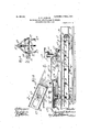
- l is a side elevation of an excavating machine embodying my invention.
- l ig. 2 is a longitudinal vertical section through the main frame and carriage, showing the p arts mounted thereupon.
- Fig. 2 is a transverse vertical section on line' 3- of Fig. 2.
- Fig. 4 is a said spacing tubes or sleeves.
- Fig. 5 is a view in elevation of the swinging cutter carrying arm; showing the reverse side from that shown in Fig. 1.
- Fig. 6 is a transverse section throu h said swing- ⁇ ing arm, taken on line 6-6 of ig. 1.
- Fig. 7 is a transverse section taken on line 7-7 of Fig. v1'.
- a A designate the side members ofthe main Wheeled frame or truck which are connected by transverse members consisting principally of tie rods A1 extending between and through the side members A and spacing sleevesor tubes A2 surrounding the tie rods and abutting at their ends against the inner faces of said side members.
- l Nuts a screw-threaded on the outerends of said rods clamp the side members between said nuts and the outer ends of Said wheeled frame is provided with flanged wheels e1 which rest and roll upon track rails B.
- Said side members, as herein shown, have the form of I-beamswith their web portions in parallel vertical planes, and the tie rods A1 extend through said webs.
- transverse members are of special form and constitute supports for parts of the machine, as will'be hereinafter described.
- Said carriage is provided with rollers or wheels c c which rest'and roll upon. track rails c1 c1 laid upon the side members of the main frame..
- the transverse members C1 and C4 are formed at their ends to provide lugs Cwhich receive the trunnions or shafts c?
- the transverse member C1 is centrally enlarged in its horizontal dimensions and is provided with a vertical opening in which is bolted a hollow bearing sleeve D depending from and integral with a horizontal plate D1- which rests upon the transverse member C and the sidemembers C C, which latter are elevated at their forward ends, as best shown in Fig. 2.
- a second horizontal plate l)2 .rests upon the plate D1 and is provided-with a central pin'oft'stud d. which extends downwardly into the hollow bearing ⁇ sleeve D..
- the parts just described The wheels @1 are iXed to the ends of axles a2 which are veniently be an electric vshaft of said motor constitute a turn-table upon which the swinging arm E of the machine and the partsv carried thereby are supported.
- the particular form of the cutter carrying arm herein shown is that of a latticed girder, it comprising two laterally separated plates E1 El, stiffened by means of angle bars E2 E2 riveted to their margins, and connected by cross-members e e (Fig. 7).
- Said cutter earrying arm is supported near its rear endupon a horizontal shaft E? which extends transversely through the side members El ⁇ and beyond said side members. , The ends of said shaft are mounted in pillow blocks E4L rising from a frame and su ported 'on the upper horizontal plate D2 o the turn-table before described.
- the arm supporting frame consists of two side plates E5 having the form of I-beams, -which are bolted at their lower iianged margins of the horizontal. plate D2, and transverse connecting struts e1 bolted or otherwise fixed rigidly to said side pla'tes.
- the horizontal shaft E3 is fixed to the cutter carryin arm and constitutes the horizontal pivot a out which the arm swings vertically, and the stud d of the upper member or plate of the turn-table constitutes the vertical pivot about which the arm swings in its horizontal movement.
- Said rotary cutter consists of a plurality of U-shaped cuttin T blades F3 F3 attached at their ends to lateral y sepa' rated plates F4 Ff* which are fixed in any suitable manner to the shaft F.
- the looped or closed portions ofthe blades are sharpened to constitute cutting edges, and the side members or legs thereof are detachably fixed to the laterally separated plates F4 F, as by the bolts shown in Figs. 1 and 5.
- a beveled gear f1 (Fig. 5).
- the eutter is driven by a motor G, which may conmotor, supported on a ⁇ bracket or shelf G1 carried by the rear end of the cutter carrying arm.
- the armature 1s connected with and drives a shaft gwhich carries at its outer end a worm g1 'meshing with a w'orm wheel G2 which is arranged between the two side members of the cutter carrying arm ⁇ and is fixed ⁇ to a shaft g2 which is -journaled in said members.
- a beveled gear g4 (Fig. ⁇ 5) which meshes with a beveled gear h fixed to'the inner end of a lon itudinal shaft H mounted in bearings 71.l h1 bo ted to the side face of the, arm, as shown in Fig'. 5.
- the arm may be raised from a lower to a higher position to adjust the cutter toa new cut on the breast of the tunnel, or other work, with the exertion of relatively small power andthe use .of relatively light actuatin mechanism as compared toa machine in wich the principal weight carried by the arm is between its pivot and the cutter.
- the free end of the arm is overweighted sufficiently to neutralize due to the reaction of the cutting blades, as 4the arm swings downwardly to bring the blades in cutting contact with the work.
- the arm is approximately counterbalanced when the cutter is in operation.
- I designates a worm gear segment which is fixed to one end of the horizontal pivot shaft E3 (Figs. 1 and 3) anddepends therefrom. Said gear segment meshes with a horizontal worm l1 beneath the level ofthe cutter carrying arm. Said wormis carried by a worm'shaft i which is journaled in bearing members il bolted to and rising from the horizontal plate-D2. To the end of said worm shaft is fixed a handwheel I2, throu h the medium of which the worm is rotate to impart, through the gear segment, vertical movement to said arm.
- the mechanism herein shown for horizontally swin ing the cutter carrying arm about its vertica axis is madev as follows: J desig* n'ates a bevel ear segment that is bolted or otherwise fixed to the upper face of the upper member D2 of the turnvtabl'e. Meshing with said segment is'a beveled gear J1 carried by a longitudinally extending, horizontal shaft J 2 w ich is journalcd in bearing mem? bers j jl'supported on the transverse members C2 C3 of the carriage (Fig. 2).
- the bearing member is formed to provide also a bearing for a s ort'vertical shaft j which carries at its lower end a beveled gear J"' gear J4 on the adjacent end of said horizontal shaft J2.
- AThe vertical shaftj3 is provided at its upper end with a hand-wheel J 5 by means of which the parts are operated to effect the horizontal adj ustment of the cutter carrying arm.
- a tunnel excavating machine comprising a wheeledframe, a carriage ,mounted on said frame, means for shifting the carriage forwardly and rearwardlyon the frame, al'
- cutter carrying arm 4 mounted at one end on said frame, a cutter carried by the free end of said arm, a motor carried by said arm for operating the cutter, and means for imparting both a vertical and horizontal swinging movement to said arm.
- a tunnel excavating machine com rising a wheeled frame, a carriage mounte on said frame, rack and pinion mechanism for shifting the carriage forwardly and rearwardly on said frame, a cuttercarrying varm ⁇ mounted at one end on the carriage, a motor' carried by the arm for operating said cutter, and means for imparting both a horizontal and vertical swinging movement to said arm.
- a tunnel excavating machine comprising a wheeled frame, a carriage mounted on the frame, means Afor shifting said carriage from front to rear of the frame comprisino ⁇ a rack on the carriage, a shaft on the whee ed frame carrying a pinion meshing with the rack, a worm-gear mechanism for rotating said. shaft, a cutter carrying arm mounted on the carriage, means for imparting both a vertical and a horizontal swinging movement to said arm, a cutter' carried by the free end of said arm, and a motor also carried by the. arm and operatively connected with the cutter.
- a tunnel excavating machine comprising a wheeled frame, a carriage mounted on said frame, means for shifting the carriage forwardly and rearwardly on said frame, a horizontally rotative turntable mounted on said carriage, a vertically swinging cutter carrying arm mounted on said turn-table, a cutter carried by the free end of the arin and a motor carried also by said arm and operatively connected with said cutter.
- a tunnel excavating machine comprising y,a cutter carrying arm, a cutter carried by theffree end of said arm, a motor carried by the arm for operating said cutter, a frame on which said arm 'is suplported, means for imparting both a vertica and horizontal swinglng movement to the arm, and a conveying derice mounted in said frame beneath the arm in position to receive the material loosenedv by the cutter for carrying the said material from the front to the rear of the machine.
- a tunnel excavating machine comprising a cutter carrying arm, aeutter carried by the free end of said arm, a motor carried by the arm for operating said cutter, ⁇ a frame on which said arm is supported, means for imparting both a' vertical and horizontal swinging movement to the arm, and a conveyer belt trained about rollers mounted beneath said frame and having a part which extends forwardly from the frame beneath said arm for carrying the material loosened by the cutter from the front to the rear of the machine.
- a tunnel excavating machine comprising a wheeled frame, a carriage thereon, means for shifting the carriage from front to rear of said frame, a swinging arm mounted on the carriage, a motor carried by the arm and operatively connected with said cutter,A means for impartmg both a vertical and a a horizontal, longitudinally'extending rack -the -beam members A of the main frame.
- K designates bar, (Figs. 1 and. 2) which is arranged centrally in the carriage frame and is fixed at its ends to the transverse members C1 to C4 of, the carriage.
- Thehteeth of said rack bar face downwardly and mesh with a pinion K1 which is journaled in bearing membersk 7c (Fig.
- Said shaft k1 is rovided at its upper end with a hand wheeFK5 by which it may be operated to rotate the pinion shaft K2 and, through the rack bar, to shift the carriage longitudinally of the main frame.
- the worm K4 and worm wheel K3 serve to lock the carriage in any p'osition to which it maybe shifted by the rack' and pinion mechanism described.
- a conveying device is provided for convey- A ing material, which isloosened by the cutter,
- Said conveying device isv constructed as follows: L designates a horizontal conveyer belt which is located between the side members of the main frame and is trained about rollers L1 L2 at the front and rear ends, respectively, of said frame.
- the forward' rol er is mounted -in aforward extension2 A6 of the side members of the-frame in order to brin the forward'part of "thel conveyor belt, close y adjacent'tolthebreastl.of.the tunnel or other work o erated upon by the machine.
- the forward roller L1 is placed as low as is practicable and to this end the extensions 'A6 are inclined downwardly and forwardly from the main frame.
- the shaft of saidforward roller is journaled in bearings l carried by said extensions A6.
- the shaft of the rearroller L2 is journaled in bearings l* mounted on the web portions of the side members of the main frame..
- idler rollers L* which are rotatively mounted, as herein shown,- on the spacing tubes A2 of the transverse members of the main frame of the machine.
- Said rollers, as herein shown, ' have bearing at their ends only on said spacing tubes, as best ⁇ shown in Fig. 3, the central parts of the rollers being free from the spacing tubes.
- the rollers are provided at their ends with hollow plugs Z'" which fit tightly in the ends of thc rollers and are formed with bearing openings of a diameter to rota-te freely on said spacing tubes.
- the lowerlap of the conveyor belt 1s likewise supported at intervals upon rollers L5 L5, two of which are journaled upon the axles of the wheels al al, :i
- Horizontal bars L7 are arranged lonritudinally -at the sides of the u per lap of t e beltconveyer to preventthe oosened material falling off of the same, as shown in Figs. 3 and 4. Said bars are attached to the side members of the frame by means of brackets ZS..
- the conveyer belt is conveniently driven by a motor M, which may bean electric motor, and which is mounted on the rear end of the main frame of themachine.
- Said motor' is'- operatively connectedwith the rear roller AL2 of the conveyor4 belt by means of a shaft mtvhich carries at i-tsupper end a beveled gear m1 -which meshes with a beveled Y gear m2, on the motor shaft.
- the shaft ym ' carries at its lower end a beveled gearm3 wheels al of the main frame arerst blockedl to hold the machine from rearward move-i ment, due to the 'action of the cutter on the tunnel breast.
- the cutter carrying arm is then adjusted, by means of the gear segment J and gear pinion J1 to present the cutter to the tunnel breast at Athe proper horizontal an-fv which is driven by! the inotorduring such swinging motion, into vertical contactwith thebreast of the tunnel and thereby remove a icc' gle. Thereafter the cutter carrying arm' -is lswungvertically about its horizontal axis,
- a tunnelvexcavating machine comprising a cutter carrying arm,- a cutter carried by the free end of said arm, a motor carried by the arm for operating said cutter, a frame on which said arm is supported, .means fork imparting both a vertical and horizontal swinging movement to the Aarm, a conveyer belt y trained about rollers mounted in said frame and extending from front to rear of the machine for carr ing the material loosened by the cutter to tlie rear end of the machine, the forward part of said conveyer belt being inclined downwardly, forthe purpose set fsrth.
Landscapes
- Engineering & Computer Science (AREA)
- Mechanical Engineering (AREA)
- Mining & Mineral Resources (AREA)
- Civil Engineering (AREA)
- General Engineering & Computer Science (AREA)
- Structural Engineering (AREA)
- Excavating Of Shafts Or Tunnels (AREA)
Description
Dr. N U ml .G
...UHU .X
.Gnu U1 .E N I un G A- M f. ,No.-889,464.
APPLICATION .FILED DBO. 6. 1`90I.
3 sums-SHEET 1.
10.889,464, 1 PATENTED JUNE 2, 190s. a. w. JACKSON. MACHINE PoR BXGAVATING' TUNNBLS.
APPLICATION FILED DBO. 6 1907.
, 3 SHEBTS-SHEET Z.
.WN mw o mW/@ NNNJ No. 889,464. PATENTED JUNE 2, 1908. G. W. JACKSON. MACHINE POR BXCAVATING TUNNELS.
APPLICATION FILED DEO. 6, 1907. 3 SHEETS-SHEET 3.
gva
lsierras. PATENT ermee.
GEORGE W. JACKSON, OF CHICAGO, ILLIOISY.
MACHINE son Ex'cAvAiiNG 'INNELs Specification of Letters Patent.
Patented .Tune 2, 1908.
Application med December s, 1907. serai No. 405,419..
`of this specification.
This invention relates to improvements in excavating machines for constructing tunnels, for mining purposes and like uses, and
the invention consistsin the matters hereinafter set forth and more particularly pointed out in the appended claims.
The excavating machine `herein shown as embodying the several features of my invention embraces, in general terms, a cutter arm having horizontally and vertically swinging movement, whereby it may be presented at. varying horizontal and vertical angles to the breast of a tunnel or other part to be excavated or removed, and said arm carries at its outer or free end a cutter for cutting or loosening the material to be cut or loosened. The said cutter arm is carried b a main wheeled frame or truck and is direct y supported on a carriage which is movable forwardly and rearwardly on said main frame. T he machine embraces also a conveyer arranged be# neath the cutter arm carriage to carry. the material loosened by the cutter to thev rear of the machine from which point it may be.
removed in any suitable manner. Movement of the carriage forwardly on the mam frame advances the .cutter toward the breast of the tunnel, or other material being excavated or cut away, through the range of movement of the carriage. When the carriage has reached the limit of its forward movement it is moved to its rearmost position and thereafter the main frame is advanced to 'bring the machine into an advanced position for operation, after which the carriage is advanced on the frame as the work proceeds in the same manner as before. i
ln the accompanying drawings :#-F igure l is a side elevation of an excavating machine embodying my invention. l ig. 2 is a longitudinal vertical section through the main frame and carriage, showing the p arts mounted thereupon. Fig. 2 is a transverse vertical section on line' 3- of Fig. 2. Fig. 4 is a said spacing tubes or sleeves.
.porting rollers Vc;
transverse vertical section on line 4 4 of Fig. 2. Fig. 5 is a view in elevation of the swinging cutter carrying arm; showing the reverse side from that shown in Fig. 1. Fig.
6 is a transverse section throu h said swing-` ing arm, taken on line 6-6 of ig. 1. Fig. 7 is a transverse section taken on line 7-7 of Fig. v1'.
ls shown in said drawings, A A designate the side members ofthe main Wheeled frame or truck which are connected by transverse members consisting principally of tie rods A1 extending between and through the side members A and spacing sleevesor tubes A2 surrounding the tie rods and abutting at their ends against the inner faces of said side members. l Nuts a screw-threaded on the outerends of said rods clamp the side members between said nuts and the outer ends of Said wheeled frame is provided with flanged wheels e1 which rest and roll upon track rails B.. Said side members, as herein shown, have the form of I-beamswith their web portions in parallel vertical planes, and the tie rods A1 extend through said webs.
mounted in journals a3 bolted to the bottom flanges of theside members A.
C C designate the longitudinal members,
riage on the main frame which directly supports the cutter carrying arm. Certain of said transverse members are of special form and constitute supports for parts of the machine, as will'be hereinafter described. Said carriage is provided with rollers or wheels c c which rest'and roll upon. track rails c1 c1 laid upon the side members of the main frame.. The transverse members C1 and C4 are formed at their ends to provide lugs Cwhich receive the trunnions or shafts c? of 'the carriage sup- The transverse member C1 is centrally enlarged in its horizontal dimensions and is provided with a vertical opening in which is bolted a hollow bearing sleeve D depending from and integral with a horizontal plate D1- which rests upon the transverse member C and the sidemembers C C, which latter are elevated at their forward ends, as best shown in Fig. 2. A second horizontal plate l)2 .rests upon the plate D1 and is provided-with a central pin'oft'stud d. which extends downwardly into the hollow bearing `sleeve D.. The parts just described The wheels @1 are iXed to the ends of axles a2 which are veniently be an electric vshaft of said motor constitute a turn-table upon which the swinging arm E of the machine and the partsv carried thereby are supported.
The particular form of the cutter carrying arm herein shown is that of a latticed girder, it comprising two laterally separated plates E1 El, stiffened by means of angle bars E2 E2 riveted to their margins, and connected by cross-members e e (Fig. 7). Said cutter earrying arm is supported near its rear endupon a horizontal shaft E? which extends transversely through the side members El` and beyond said side members. ,The ends of said shaft are mounted in pillow blocks E4L rising from a frame and su ported 'on the upper horizontal plate D2 o the turn-table before described. The arm supporting frame consists of two side plates E5 having the form of I-beams, -which are bolted at their lower iianged margins of the horizontal. plate D2, and transverse connecting struts e1 bolted or otherwise fixed rigidly to said side pla'tes. The horizontal shaft E3 is fixed to the cutter carryin arm and constitutes the horizontal pivot a out which the arm swings vertically, and the stud d of the upper member or plate of the turn-table constitutes the vertical pivot about which the arm swings in its horizontal movement.
To the forward end of the cutter carrying arm are bolted a pair of journal members f in which is journaled a horizontal shaft F which carries a rotary cutter F1 that is constructed4 as follows: Said rotary cutter consists of a plurality of U-shaped cuttin T blades F3 F3 attached at their ends to lateral y sepa' rated plates F4 Ff* which are fixed in any suitable manner to the shaft F. The looped or closed portions ofthe blades are sharpened to constitute cutting edges, and the side members or legs thereof are detachably fixed to the laterally separated plates F4 F, as by the bolts shown in Figs. 1 and 5. One end of said cutter shaft F,extends beyond its bearing member j, and to said extended shaft end is fixed a beveled gear f1 (Fig. 5). The eutter is driven by a motor G, which may conmotor, supported on a` bracket or shelf G1 carried by the rear end of the cutter carrying arm. The armature 1s connected with and drives a shaft gwhich carries at its outer end a worm g1 'meshing with a w'orm wheel G2 which is arranged between the two side members of the cutter carrying arm` and is fixed `to a shaft g2 which is -journaled in said members. The outer end of the worm shaft g is journaled in a bearing g3 which is supported on the side members of said arm, as most clearly shown in Figs. 1, 5 and 6: To one. end of said shaft g2 is iixed a beveled gear g4 (Fig.`5) which meshes with a beveled gear h fixed to'the inner end of a lon itudinal shaft H mounted in bearings 71.l h1 bo ted to the side face of the, arm, as shown in Fig'. 5. The
f tically about its Y meshing with a beveled outer' end of said shaft H gear h2 which meshes with the beveled. gear j" of the cutter shaft. F. By means of the gearing described the cutter F is rotated and carries a beveled the .proportions of the gears are such that the with respectto the pivot shaft E3 of the arm,
ht of the motor tends to counterbalance vt e weight of that partk of the arm between the pivot shaft and thecutter. Thus the arm may be raised from a lower to a higher position to adjust the cutter toa new cut on the breast of the tunnel, or other work, with the exertion of relatively small power andthe use .of relatively light actuatin mechanism as compared toa machine in wich the principal weight carried by the arm is between its pivot and the cutter. The free end of the arm is overweighted sufficiently to neutralize due to the reaction of the cutting blades, as 4the arm swings downwardly to bring the blades in cutting contact with the work. Thus the arm is approximately counterbalanced when the cutter is in operation.
Next referring to the mechanism herein shown for actuating the arm to swing it ver-A horizontal axis, said parts are made as followsn I designates a worm gear segment which is fixed to one end of the horizontal pivot shaft E3 (Figs. 1 and 3) anddepends therefrom. Said gear segment meshes with a horizontal worm l1 beneath the level ofthe cutter carrying arm. Said wormis carried by a worm'shaft i which is journaled in bearing members il bolted to and rising from the horizontal plate-D2. To the end of said worm shaft is fixed a handwheel I2, throu h the medium of which the worm is rotate to impart, through the gear segment, vertical movement to said arm.
The mechanism herein shown for horizontally swin ing the cutter carrying arm about its vertica axis is madev as follows: J desig* n'ates a bevel ear segment that is bolted or otherwise fixed to the upper face of the upper member D2 of the turnvtabl'e. Meshing with said segment is'a beveled gear J1 carried by a longitudinally extending, horizontal shaft J 2 w ich is journalcd in bearing mem? bers j jl'supported on the transverse members C2 C3 of the carriage (Fig. 2). The bearing member is formed to provide also a bearing for a s ort'vertical shaft j which carries at its lower end a beveled gear J"' gear J4 on the adjacent end of said horizontal shaft J2. AThe vertical shaftj3 is provided at its upper end with a hand-wheel J 5 by means of which the parts are operated to effect the horizontal adj ustment of the cutter carrying arm. v
Any suitable means may be employed for that the wei the'average thrust on the arm,I
. larity as to details many of such 'details' of poses than those herein speciiicall construction may be' varied without'de arture from the spirit of my invention. oref over certain of the essential elements of the machine may be employed for other pury set forth.
I claim as my invention f 1. A tunnel excavating machine comprising a wheeledframe, a carriage ,mounted on said frame, means for shifting the carriage forwardly and rearwardlyon the frame, al'
cutter carrying arm 4mounted at one end on said frame, a cutter carried by the free end of said arm, a motor carried by said arm for operating the cutter, and means for imparting both a vertical and horizontal swinging movement to said arm.
2. A tunnel excavating machine com rising a wheeled frame, a carriage mounte on said frame, rack and pinion mechanism for shifting the carriage forwardly and rearwardly on said frame, a cuttercarrying varm `mounted at one end on the carriage, a motor' carried by the arm for operating said cutter, and means for imparting both a horizontal and vertical swinging movement to said arm.
8'. A tunnel excavating machine comprising a wheeled frame, a carriage mounted on the frame, means Afor shifting said carriage from front to rear of the frame comprisino` a rack on the carriage, a shaft on the whee ed frame carrying a pinion meshing with the rack, a worm-gear mechanism for rotating said. shaft, a cutter carrying arm mounted on the carriage, means for imparting both a vertical and a horizontal swinging movement to said arm, a cutter' carried by the free end of said arm, and a motor also carried by the. arm and operatively connected with the cutter.
4. A tunnel excavating machine comprising a wheeled frame, a carriage mounted on said frame, means for shifting the carriage forwardly and rearwardly on said frame, a horizontally rotative turntable mounted on said carriage, a vertically swinging cutter carrying arm mounted on said turn-table, a cutter carried by the free end of the arin and a motor carried also by said arm and operatively connected with said cutter.
5. The combination with a supporting lralne, of a horizontally and vertically swingingarln lknounted thereon, a cutter carriedby v6. The combination with a sulpporting" frame, of a horizontally and vertical r swinging arm mounted thereon, a cutter carried by the free end of said arm, and a motor'for operating said'cutter and carried by the arm on the side of its horizontal Apivot remote from said cutter, whereby the motor'and the rear end of the arm tend to counterbalance the end of the arm which carries the cutter, the arm being so proportioned `with respect. to its pivot that the free endthereof slightly overbalances the motorv and the part of the arm in rear of saidhorizontal pivot. 7. The combinationv with a supporting frame, of a horizontally rotative turn-table mounted thereon, a vertically swinging arm mounted on a horizontalpivot carried lby said turn-table, a cutter carried bythe free end .of said arm, a motor mounted also on said arm and operatively connected with said cutter, and means for swinging the arm vertically on its horizontal pivot comprising a gear y segment mounted on and concentric with said pivot and depending therefrom, and a horizontal worm mounted on said fram f below the level of the arm and meshing' With/said worm-gear segment.
. 8./ A tunnel excavating machine comprising y,a cutter carrying arm, a cutter carried by theffree end of said arm, a motor carried by the arm for operating said cutter, a frame on which said arm 'is suplported, means for imparting both a vertica and horizontal swinglng movement to the arm, and a conveying derice mounted in said frame beneath the arm in position to receive the material loosenedv by the cutter for carrying the said material from the front to the rear of the machine. f`
' 9. A tunnel excavating machine comprising a cutter carrying arm, aeutter carried by the free end of said arm, a motor carried by the arm for operating said cutter,\a frame on which said arm is supported, means for imparting both a' vertical and horizontal swinging movement to the arm, and a conveyer belt trained about rollers mounted beneath said frame and having a part which extends forwardly from the frame beneath said arm for carrying the material loosened by the cutter from the front to the rear of the machine.
10. A tunnel excavating machine comprising a wheeled frame, a carriage thereon, means for shifting the carriage from front to rear of said frame, a swinging arm mounted on the carriage, a motor carried by the arm and operatively connected with said cutter,A means for impartmg both a vertical and a a horizontal, longitudinally'extending rack -the -beam members A of the main frame.
carried by a\transverse, horizontal shaft K2 In order to fac upper lap of the convever belt is'supported shifting the cutter arm supporting carriage to present the cutter to or retract it from the work. The mechanism herein shown for this purpose is made as follows: K designates bar, (Figs. 1 and. 2) which is arranged centrally in the carriage frame and is fixed at its ends to the transverse members C1 to C4 of, the carriage. Thehteeth of said rack bar face downwardly and mesh with a pinion K1 which is journaled in bearing membersk 7c (Fig. 4) which are fixed to the top flanges of Said shaft is provided at one end thereof with a worm wheel K3 which meshes with a worm K* on a vertical worm shaft 7s" that is journaled in a bearing member k2 fixed to the adjacent frame member A. Said shaft k1 is rovided at its upper end with a hand wheeFK5 by which it may be operated to rotate the pinion shaft K2 and, through the rack bar, to shift the carriage longitudinally of the main frame. The worm K4 and worm wheel K3 serve to lock the carriage in any p'osition to which it maybe shifted by the rack' and pinion mechanism described. Y
A conveying device is provided for convey- A ing material, which isloosened by the cutter,
from the front to the rear of the machine, from which latter point said material may be removed in any suitable orlpreferred manner. Said conveying device isv constructed as follows: L designates a horizontal conveyer belt which is located between the side members of the main frame and is trained about rollers L1 L2 at the front and rear ends, respectively, of said frame. The forward' rol er is mounted -in aforward extension2 A6 of the side members of the-frame in order to brin the forward'part of "thel conveyor belt, close y adjacent'tolthebreastl.of.the tunnel or other work o erated upon by the machine.
itate the reception of material by the belt, the forward roller L1 is placed as low as is practicable and to this end the extensions 'A6 are inclined downwardly and forwardly from the main frame. The shaft of saidforward roller is journaled in bearings l carried by said extensions A6. The shaft of the rearroller L2 is journaled in bearings l* mounted on the web portions of the side members of the main frame.. The
at intervals by idler rollers L* which are rotatively mounted, as herein shown,- on the spacing tubes A2 of the transverse members of the main frame of the machine. Said rollers, as herein shown, 'have bearing at their ends only on said spacing tubes, as best` shown in Fig. 3, the central parts of the rollers being free from the spacing tubes. To` this end the rollers are provided at their ends with hollow plugs Z'" which fit tightly in the ends of thc rollers and are formed with bearing openings of a diameter to rota-te freely on said spacing tubes. The lowerlap of the conveyor belt 1s likewise supported at intervals upon rollers L5 L5, two of which are journaled upon the axles of the wheels al al, :i
and another or intermediate one of which is `journaled in bearing members l* fastened to ,the bottom flanges of the sideframe members A. Horizontal bars L7 are arranged lonritudinally -at the sides of the u per lap of t e beltconveyer to preventthe oosened material falling off of the same, as shown in Figs. 3 and 4. Said bars are attached to the side members of the frame by means of brackets ZS..
The conveyer belt is conveniently driven by a motor M, which may bean electric motor, and which is mounted on the rear end of the main frame of themachine. Said motor'is'- operatively connectedwith the rear roller AL2 of the conveyor4 belt by means of a shaft mtvhich carries at i-tsupper end a beveled gear m1 -which meshes with a beveled Y gear m2, on the motor shaft. The shaft ym 'carries at its lower end a beveled gearm3 wheels al of the main frame arerst blockedl to hold the machine from rearward move-i ment, due to the 'action of the cutter on the tunnel breast. The cutter carrying arm is then adjusted, by means of the gear segment J and gear pinion J1 to present the cutter to the tunnel breast at Athe proper horizontal an-fv which is driven by! the inotorduring such swinging motion, into vertical contactwith thebreast of the tunnel and thereby remove a icc' gle. Thereafter the cutter carrying arm' -is lswungvertically about its horizontal axis,
through the medium of the worm gear segment I andworm I1 so as to carry the cutter,
layer of earth of the width ofthe cutter blades' c, 1n each vertical swing of the arm. After each vertical layer of the tunnel breast hasbee'n thus removed, thecutter arm is swung horizontally to present the cutter at another horie zontal angle to the tunnel breast, and another layencut away during the subsequent vertical swing of the arm. This operation is repeated until a section of the'en'tire breast has been removed, after which the carriage is advanced, byr'the rack and pinion mechanism described, to bring the cutter into position for' removing another section or layer ofthe tunnel breast in kthe same 'manner as before. From time to time the entire machine is moved forward on its track and is blocked to hold it in place. The loose material removed from the breast of the tunnel falls to the bot'- tom of the tunnel. Some of this material falls directly on the forward part of thereuhorizontal swinging movement to said arm,
c to the rear of the machine.
11. A tunnelvexcavating machine comprising a cutter carrying arm,- a cutter carried by the free end of said arm, a motor carried by the arm for operating said cutter, a frame on which said arm is supported, .means fork imparting both a vertical and horizontal swinging movement to the Aarm, a conveyer belt y trained about rollers mounted in said frame and extending from front to rear of the machine for carr ing the material loosened by the cutter to tlie rear end of the machine, the forward part of said conveyer belt being inclined downwardly, forthe purpose set fsrth.
12. The combination with a su porting frame, of a horizontally and vertical y swinging cutter carrying arm mounted thereon and extending forwardly therefrom, a cutter carried by the free end of said arm, means for operating said cutter and a conveyer belt arranged With its receiving end in front of said frame and below the arm for conveyingthe material from the Ifront end of the machine.
In testimony, that I claim the foregoing as my invention I affix my signature in the resence of two witnesses, this 12th day o November A, D. 1907.
GEORGE W. JACKSON.
Priority Applications (1)
| Application Number | Priority Date | Filing Date | Title |
|---|---|---|---|
| US40541907A US889464A (en) | 1907-12-06 | 1907-12-06 | Machine for excavating tunnels. |
Applications Claiming Priority (1)
| Application Number | Priority Date | Filing Date | Title |
|---|---|---|---|
| US40541907A US889464A (en) | 1907-12-06 | 1907-12-06 | Machine for excavating tunnels. |
Publications (1)
| Publication Number | Publication Date |
|---|---|
| US889464A true US889464A (en) | 1908-06-02 |
Family
ID=2957895
Family Applications (1)
| Application Number | Title | Priority Date | Filing Date |
|---|---|---|---|
| US40541907A Expired - Lifetime US889464A (en) | 1907-12-06 | 1907-12-06 | Machine for excavating tunnels. |
Country Status (1)
| Country | Link |
|---|---|
| US (1) | US889464A (en) |
Cited By (7)
| Publication number | Priority date | Publication date | Assignee | Title |
|---|---|---|---|---|
| DE943217C (en) * | 1951-09-01 | 1956-05-17 | Buckau Wolf Maschf R | Conveyor equipment such as spreaders, excavators or the like with a conveyor which can be pivoted in a horizontal and vertical plane and is provided with a counterweight arm |
| DE963410C (en) * | 1948-10-02 | 1957-05-09 | Eisen & Stahlind Ag | Bucket wheel excavator |
| DE964490C (en) * | 1950-12-17 | 1957-05-29 | Eisen & Stahlind Ag | Excavators, in particular bucket wheel excavators |
| DE968090C (en) * | 1951-07-15 | 1958-01-16 | Eisen & Stahlind Ag | Bucket wheel boom head |
| DE968210C (en) * | 1950-03-30 | 1958-01-23 | Eisen & Stahlind Ag | Bucket wheel excavators, especially for large cutting heights |
| DE975026C (en) * | 1951-06-02 | 1961-07-06 | Oskar Dipl-Ing Weidemann | Bucket wheel excavator |
| US3001303A (en) * | 1959-11-27 | 1961-09-26 | Joseph E Hampton | Ditching machine |
-
1907
- 1907-12-06 US US40541907A patent/US889464A/en not_active Expired - Lifetime
Cited By (7)
| Publication number | Priority date | Publication date | Assignee | Title |
|---|---|---|---|---|
| DE963410C (en) * | 1948-10-02 | 1957-05-09 | Eisen & Stahlind Ag | Bucket wheel excavator |
| DE968210C (en) * | 1950-03-30 | 1958-01-23 | Eisen & Stahlind Ag | Bucket wheel excavators, especially for large cutting heights |
| DE964490C (en) * | 1950-12-17 | 1957-05-29 | Eisen & Stahlind Ag | Excavators, in particular bucket wheel excavators |
| DE975026C (en) * | 1951-06-02 | 1961-07-06 | Oskar Dipl-Ing Weidemann | Bucket wheel excavator |
| DE968090C (en) * | 1951-07-15 | 1958-01-16 | Eisen & Stahlind Ag | Bucket wheel boom head |
| DE943217C (en) * | 1951-09-01 | 1956-05-17 | Buckau Wolf Maschf R | Conveyor equipment such as spreaders, excavators or the like with a conveyor which can be pivoted in a horizontal and vertical plane and is provided with a counterweight arm |
| US3001303A (en) * | 1959-11-27 | 1961-09-26 | Joseph E Hampton | Ditching machine |
Similar Documents
| Publication | Publication Date | Title |
|---|---|---|
| US889464A (en) | Machine for excavating tunnels. | |
| US997638A (en) | Pavement-breaking machine. | |
| US2384397A (en) | Machine for driving slopes and air courses in mines | |
| US1792148A (en) | Ballast-cleaning machine | |
| US527051A (en) | Wash inqtoh | |
| US747869A (en) | Excavating-machine. | |
| US550152A (en) | Excavator | |
| US624400A (en) | Channeling-com minuter | |
| US917821A (en) | Ditching-machine. | |
| US2607136A (en) | Bucket cleaner for trench digging machines | |
| US1573125A (en) | Automatic loader | |
| US1299826A (en) | Excavating-machine. | |
| US1329673A (en) | Earth-excavating and wagon-loading machine | |
| US1796889A (en) | Excavating machine | |
| US1316999A (en) | Ditching-machine | |
| US908820A (en) | Excavating, grading, and conveying machine. | |
| US1753804A (en) | Shale planer | |
| US1194375A (en) | Sheet i | |
| US820152A (en) | Excavating and ditching machine. | |
| US275534A (en) | Means for deepening the channels of rivers | |
| US523790A (en) | Traction ditching-machine | |
| US1579704A (en) | Mining machine | |
| US208497A (en) | Improvement in grading and ditching machines | |
| US1100414A (en) | Ditching-machine. | |
| US1741321A (en) | Edging machine |