US8868110B2 - Wireless communication device capable of efficient network search - Google Patents
Wireless communication device capable of efficient network search Download PDFInfo
- Publication number
- US8868110B2 US8868110B2 US13/341,627 US201113341627A US8868110B2 US 8868110 B2 US8868110 B2 US 8868110B2 US 201113341627 A US201113341627 A US 201113341627A US 8868110 B2 US8868110 B2 US 8868110B2
- Authority
- US
- United States
- Prior art keywords
- wireless communication
- communication device
- frequency
- base station
- bandwidth
- Prior art date
- Legal status (The legal status is an assumption and is not a legal conclusion. Google has not performed a legal analysis and makes no representation as to the accuracy of the status listed.)
- Expired - Fee Related, expires
Links
- 238000004891 communication Methods 0.000 title claims abstract description 169
- 238000000926 separation method Methods 0.000 claims description 6
- 239000000969 carrier Substances 0.000 claims description 3
- 230000007774 longterm Effects 0.000 claims 1
- 238000000034 method Methods 0.000 abstract description 38
- 230000008569 process Effects 0.000 abstract description 6
- 238000005516 engineering process Methods 0.000 abstract description 5
- 241000700159 Rattus Species 0.000 description 21
- 238000010586 diagram Methods 0.000 description 17
- 238000012545 processing Methods 0.000 description 14
- 238000012937 correction Methods 0.000 description 5
- 238000001914 filtration Methods 0.000 description 5
- 230000006870 function Effects 0.000 description 5
- 238000012986 modification Methods 0.000 description 5
- 230000004048 modification Effects 0.000 description 5
- 238000012360 testing method Methods 0.000 description 3
- 230000008901 benefit Effects 0.000 description 2
- 230000010267 cellular communication Effects 0.000 description 2
- 230000010363 phase shift Effects 0.000 description 2
- 238000012552 review Methods 0.000 description 2
- 208000031481 Pathologic Constriction Diseases 0.000 description 1
- 230000006978 adaptation Effects 0.000 description 1
- 230000005540 biological transmission Effects 0.000 description 1
- 230000001413 cellular effect Effects 0.000 description 1
- 238000006243 chemical reaction Methods 0.000 description 1
- 125000004122 cyclic group Chemical group 0.000 description 1
- 238000001514 detection method Methods 0.000 description 1
- 239000000284 extract Substances 0.000 description 1
- 238000013208 measuring procedure Methods 0.000 description 1
- 230000007246 mechanism Effects 0.000 description 1
- 230000003287 optical effect Effects 0.000 description 1
- 230000008520 organization Effects 0.000 description 1
- 230000010355 oscillation Effects 0.000 description 1
- 230000002093 peripheral effect Effects 0.000 description 1
- 238000012956 testing procedure Methods 0.000 description 1
- 230000035899 viability Effects 0.000 description 1
Images


Classifications
-
- H—ELECTRICITY
- H04—ELECTRIC COMMUNICATION TECHNIQUE
- H04W—WIRELESS COMMUNICATION NETWORKS
- H04W88/00—Devices specially adapted for wireless communication networks, e.g. terminals, base stations or access point devices
- H04W88/02—Terminal devices
-
- H—ELECTRICITY
- H04—ELECTRIC COMMUNICATION TECHNIQUE
- H04W—WIRELESS COMMUNICATION NETWORKS
- H04W36/00—Hand-off or reselection arrangements
- H04W36/08—Reselecting an access point
-
- H—ELECTRICITY
- H04—ELECTRIC COMMUNICATION TECHNIQUE
- H04W—WIRELESS COMMUNICATION NETWORKS
- H04W36/00—Hand-off or reselection arrangements
- H04W36/24—Reselection being triggered by specific parameters
- H04W36/32—Reselection being triggered by specific parameters by location or mobility data, e.g. speed data
- H04W36/322—Reselection being triggered by specific parameters by location or mobility data, e.g. speed data by location data
-
- H—ELECTRICITY
- H04—ELECTRIC COMMUNICATION TECHNIQUE
- H04W—WIRELESS COMMUNICATION NETWORKS
- H04W48/00—Access restriction; Network selection; Access point selection
- H04W48/16—Discovering, processing access restriction or access information
-
- H—ELECTRICITY
- H04—ELECTRIC COMMUNICATION TECHNIQUE
- H04W—WIRELESS COMMUNICATION NETWORKS
- H04W48/00—Access restriction; Network selection; Access point selection
- H04W48/20—Selecting an access point
-
- H—ELECTRICITY
- H04—ELECTRIC COMMUNICATION TECHNIQUE
- H04W—WIRELESS COMMUNICATION NETWORKS
- H04W64/00—Locating users or terminals or network equipment for network management purposes, e.g. mobility management
- H04W64/003—Locating users or terminals or network equipment for network management purposes, e.g. mobility management locating network equipment
-
- H—ELECTRICITY
- H04—ELECTRIC COMMUNICATION TECHNIQUE
- H04W—WIRELESS COMMUNICATION NETWORKS
- H04W88/00—Devices specially adapted for wireless communication networks, e.g. terminals, base stations or access point devices
- H04W88/02—Terminal devices
- H04W88/06—Terminal devices adapted for operation in multiple networks or having at least two operational modes, e.g. multi-mode terminals
-
- Y—GENERAL TAGGING OF NEW TECHNOLOGICAL DEVELOPMENTS; GENERAL TAGGING OF CROSS-SECTIONAL TECHNOLOGIES SPANNING OVER SEVERAL SECTIONS OF THE IPC; TECHNICAL SUBJECTS COVERED BY FORMER USPC CROSS-REFERENCE ART COLLECTIONS [XRACs] AND DIGESTS
- Y02—TECHNOLOGIES OR APPLICATIONS FOR MITIGATION OR ADAPTATION AGAINST CLIMATE CHANGE
- Y02D—CLIMATE CHANGE MITIGATION TECHNOLOGIES IN INFORMATION AND COMMUNICATION TECHNOLOGIES [ICT], I.E. INFORMATION AND COMMUNICATION TECHNOLOGIES AIMING AT THE REDUCTION OF THEIR OWN ENERGY USE
- Y02D30/00—Reducing energy consumption in communication networks
- Y02D30/70—Reducing energy consumption in communication networks in wireless communication networks
Definitions
- the invention relates to wireless communications, and more specifically to a wireless communication device that is capable of efficiently searching a wireless communication network.
- Wireless communication devices such as cellular telephones to provide an example, are becoming commonplace in both personal and commercial settings.
- the wireless communication devices provide users with access to all kinds of information, as well as the ability to communicate with other such devices across large distances.
- a user can access the internet through an internet browser on the device, download miniature applications (e.g., “apps”) from a digital marketplace, send and receive emails, or make telephone calls using a voice over internet protocol (VoIP). Consequently, wireless communication devices provide users with significant mobility, while allowing them to remain “connected” to communication channels and information.
- applications e.g., “apps”
- VoIP voice over internet protocol
- Wireless communication devices communicate with one or more other wireless communication devices or wireless access points to send and receive data.
- a first wireless communication device generates and transmits a radio frequency signal modulated with encoded information. This radio frequency signal is transmitted into a wireless environment and is received by a second wireless communication device.
- the second wireless communication device demodulates and decodes the received signal to obtain the information.
- the second wireless communication device may then respond in a similar manner.
- the wireless communication devices can communicate with each other or with access points using any well-known modulation scheme, including simple amplitude modulation (AM), simple frequency modulation (FM), quadrature amplitude modulation (QAM), phase shift keying (PSK), quadrature phase shift keying (QPSK), and/or orthogonal frequency-division multiplexing (OFDM), as well as any other communication scheme that is now, or will be, known.
- modulation scheme including simple amplitude modulation (AM), simple frequency modulation (FM), quadrature amplitude modulation (QAM), phase shift keying (PSK), quadrature phase shift keying (QPSK), and/or orthogonal frequency-division multiplexing (OFDM), as well as any other communication scheme that is now, or will be, known.
- AM simple amplitude modulation
- FM simple frequency modulation
- QAM quadrature amplitude modulation
- PSK phase shift keying
- QPSK quadrature phase shift keying
- OFDM orthogonal frequency-
- wireless communication devices During communication with a current base station, or prior to such communication, wireless communication devices repeatedly search for available base stations within the wireless communication network. This may be performed in order to establish an initial connection, or to determine whether a handoff should be initiated, as well as for many other reasons.
- FIG. 1 illustrates a block diagram of a wireless communication environment.
- FIG. 2A illustrates a block diagram of a wireless communication device that is implemented as part of the wireless communication environment.
- FIG. 2B illustrates a block diagram of portions of a radio module and a controller module that may be implemented within the wireless communication device.
- FIG. 3 illustrates a diagram of a frequency band searched by the wireless communication device.
- FIG. 4 illustrates a magnified diagram of a portion of the frequency band searched by the wireless communication device.
- FIG. 5 illustrates a block diagram of a method of performing an optimized network search based on stored cell information that may be implemented by the wireless communication device.
- FIG. 6 illustrates a block diagram of a method for performing a multi-RAT network search that may be implemented by the wireless communication device.
- FIG. 7 illustrates a block diagram of a method for locating base stations within a frequency band that may be implemented by the wireless communication device, according to an exemplary embodiment
- FIG. 8 illustrates a block diagram of a method for determining base station parameters and adjusting a radio module of the wireless communication device that may be implemented by the wireless communication device.
- Embodiments of the disclosure may be implemented in hardware (e.g., circuits), firmware, software, or any combination thereof. Embodiments of the disclosure may also be implemented as instructions stored on a machine-readable medium, which may be read and executed by one or more processors.
- a machine-readable medium may include any tangible mechanism for storing or transmitting information in a form readable by a machine (e.g., a computing device).
- a machine-readable medium may include read only memory (ROM); random access memory (RAM); magnetic disk storage media; optical storage media; flash memory devices; and others.
- firmware, software, routines, instructions may be described herein as performing certain actions. However, it should be appreciated that such descriptions are merely for convenience and that such actions in fact results from computing devices, processors, controllers, or other devices executing the firmware, software, routines, instructions, etc.
- module shall be understood to include at least one of software, firmware, and hardware (such as one or more circuit, microchip, or device, or any combination thereof), and any combination thereof.
- each module may include one, or more than one, component within an actual device, and each component that forms a part of the described module may function either cooperatively or independently of any other component forming a part of the module.
- multiple modules described herein may represent a single component within an actual device.
- FIG. 1 illustrates a block diagram of a wireless communication environment 100 according to an exemplary embodiment of the disclosure.
- the wireless communication environment 100 provides wireless communication of information, such as one or more commands and/or data, between wireless communication devices.
- the wireless communication devices may each be implemented as a standalone or a discrete device, such as a mobile telephone, or may be incorporated within or coupled to another electrical device or host device, such as a portable computing device, a camera, or a Global Positioning System (GPS) unit or another computing device such as a personal digital assistant, a video gaming device, a laptop, a desktop computer, or a tablet, a computer peripheral such as a printer or a portable audio and/or video player to provide some examples and/or any other suitable electronic device that will be apparent to those skilled in the relevant art(s) without departing from the spirit and scope of the invention.
- GPS Global Positioning System
- the exemplary wireless communication environment 100 includes a first wireless communication device 110 and a second wireless communication device 150 .
- the first wireless communication device 110 may represent an exemplary embodiment of a user equipment and the second wireless communication device 150 may represent an exemplary embodiment of a second user equipment or a base station within a cellular communications network.
- the first wireless communication device 110 transmits a first wireless signal 115 toward the second wireless communication device 150 using any acceptable modulation scheme.
- the second wireless communication device 150 receives the first wireless signal 115 .
- the second wireless communication device 150 processes the received first communication signal and, if necessary, transmits a second wireless signal 155 back to the first wireless communication device 110 . In this manner, the first wireless communication device 110 and the second wireless communication device 150 exchange information (“communicate”) with one another.
- FIG. 2A illustrates a block diagram of a wireless communication device 200 that is implemented as part of the wireless communication environment 100 according to an exemplary embodiment of the invention.
- the wireless communication device 200 includes a radio module 210 and a memory module 230 , and may represent an exemplary embodiment of the first wireless communication device 110 or the second wireless communication device 150 .
- the wireless communication device 200 includes a controller module 220 that performs most of the functions within the wireless communication device 200 , including background processing, signal processing, and control.
- the controller module 220 is connected to each of the radio module 210 and the memory module 230 .
- the radio module 210 receives signals from, and transmits signals to, the wireless communication environment 100 via an antenna 201 .
- the radio module 210 may include one or more receiver chains for receiving and front-end processing signals.
- the radio module 210 Upon receipt of signals from the wireless communication environment 100 , the radio module 210 performs front-end processing on the received signals and forwards the received signals to the controller module 220 .
- the front-end processing may include demodulation, decoding and analog-to-digital conversion, among other processings.
- the controller module 220 may also control the operation of, and generate signals for transmission by, the radio module 210 .
- the controller module 220 stores viable cell information in the memory module 230 for later use.
- the viable cell information may be obtained from actual cells to which the wireless communication device 200 is or has been connected or may be obtained from network searches, or in any other manner within the spirit and scope of the present disclosure.
- the viable cell information should at least include cell location, as well as any other information that may be needed for future searching, such as cell range, cell RAT (radio access technology) capabilities, etc.
- the wireless communication device 200 further includes a sorting module 240 and a location module 250 , which are both utilized during network searches, and whose functions will be discussed in detail below.
- the controller module 220 controls the wireless communication device 200 to perform a network search for nearby base stations.
- the controller module 220 also retrieves a current location of the wireless communication device 200 from the location module 250 .
- the location module may be a GPS (global positioning system) receiver unit, or any other device capable of determine with relative accuracy the position of the wireless communication device.
- the controller module 220 searches the memory module 230 for stored cells that fall within the vicinity of the received location (whose distance from the wireless communication device does not exceed a predetermined threshold). These cells can be identified based on their corresponding positions, which were stored along with their identification information. The controller module 220 determines how many cells fall within the location parameters are stored in the memory module 230 .
- the controller module 220 determines that there are no stored cells falling within the vicinity of the received location, the controller module 220 initiates a full network search (discussed below). Alternatively, if the controller module 220 determines that there is only one stored cell that falls within the vicinity of the received location, the controller module 220 selects the cell and proceeds to test the cell for usability. If the cell is not found on the stored center frequency, the controller module 220 preferably causes the radio module 210 to search for the existence of any other cell located on the selected center frequency and/or radio access technology (RAT) before exiting the selected frequency.
- RAT radio access technology
- the controller module 220 determines that there is more than one cell stored in the memory module 230 that fall within the vicinity of the received location, the controller module 220 causes the sorting module 240 to perform a sorting operation on the plurality of cells.
- the sorting module 240 retrieves the cell information identified by the controller module 220 (the cells falling within the vicinity of the current location). The sorting module 240 then reviews several pieces of information stored in the memory module 230 in association with those cells. For example, the sorting module 240 may review, with respect to each cell, the actual distance from the cell to the current location, the last time the cell was used, average RSRP (reference signal received power), average RSRQ (reference signal received quality), RAT capabilities, and/or QoS (quality of service) parameters of the cell.
- the sorting module 240 sorts the viable cells, with the cell determined to be the best candidate for selection at the top of the order, and the cell determined to be the worst candidate for selection at the bottom of the order. For example, a cell located very close to the current device location that was very recently used will be located higher in the sorted list of cells than a cell located further away from the current location that has not yet been used.
- the sorting module 240 sends the sorted cell list to the controller module 220 .
- the controller module 220 retrieves the information (e.g. frequency) from the memory module 230 associated with the first cell in the sorted cell list.
- the controller module 220 then causes the radio module 210 to tune to the frequency associated with the selected cell and proceeds to test and measure the selected cell for viability.
- the cell may be found to be inadequate for numerous reasons, including that the cell ID of the selected cell cannot be found, the cell is overburdened, the cell exhibits poor connection quality, etc.
- controller module 220 determines the first cell of the list to be inadequate (for any of the reasons discussed above), the controller module 220 repeats the testing and measuring procedures for subsequent cells in the list until an acceptable cell is discovered. If the controller module 220 traverses the entire sorted list without finding an acceptable cell, the controller module 220 initiates a full network search (discussed below).
- the controller module 220 is unable to acquire the location information of the wireless communication device 200 .
- the location module 250 may be malfunctioning, may be absent from the wireless communication device 200 , or may be unable to currently determine a location (e.g., unable to connect to GPS satellites).
- the controller module 220 controls the sorting module 240 to perform a sorting operation on all cells stored in the memory module 230 .
- the sorting module 240 accesses the cell information for all the cells stored in the memory module 230 .
- the sorting module 240 then performs a sorting operation on the stored cells, giving extra weight to how recently the stored cell was used. Specifically, because there is no location information, the sorting module 240 presumes that cells recently used are more likely to be within the vicinity of the wireless communication device 200 than cells used further in the past.
- the controller module 220 proceeds to tune the radio module 210 to the first cell for testing and measuring. As discussed above, the controller module 220 cycles through the sorted list of cells until an acceptable cell is discovered. If no acceptable cell is discovered from among the stored cells, the controller module 220 initiates a full network search (discussed below).
- the sorting module 240 may sort the stored cells based on more or fewer factors than those listed.
- the controller module 220 may search for cells located at or near the same center frequency before moving to the next cell on the sorted list. In this manner, the controller module 220 avoids having to retune the radio module 210 , which is a particularly time-consuming operation.
- the controller module 220 initiates a full network search.
- the wireless communication device 200 is capable of communicating over multiple different RATs (e.g., 2G, 3G, 4G, etc.) the full network search preferably includes a search of each RAT.
- each RAT is searched individually frequency-by-frequency, which is an extremely long process.
- the wireless communication device 200 can simultaneously search all RATs.
- FIG. 2B illustrates a block diagram of an exemplary configuration of the radio module 210 and the controller module 220 that may be incorporated within the wireless communication device 200 .
- the radio module 210 includes an analog-to-digital converter 215 .
- the controller module 220 includes a mixing module 224 having mixers 224 a - c , and a searching module 226 that includes RAT searchers 226 a - c.
- the controller module 220 When the controller module 220 initiates a full network search, the controller module 220 sets a center frequency CF and a bandwidth BW for the radio module 210 .
- the center frequency and bandwidth are set so as to encompass all available RATs.
- signals from all the RATs are received by the antenna 201 in analog form.
- the radio module 210 receives the analog signals from the antenna 201 .
- the ADC 215 then converts the received analog signals to digital form and sends the digital signals to the mixing module 224 of the controller module 220 .
- the wireless communication device 200 searches for a base station. This can be performed for each of multiple RATs in different ways.
- the wireless communication device 200 is not aware in advance of the center frequencies on which the different RATs communicate. In this case, the wireless communication device 200 can attempt to process all RATs simultaneously.
- the wireless communication device 200 sets a bandwidth of the radio module 210 sufficient to cover synchronization signals from all RATs. For example, if BW 1 , BW 2 , and BW 3 are the minimum bandwidths required for each RAT synchronization, respectively, then the wireless communication device 200 sets the bandwidth of the radio module 210 to be the maximum of BW 1 , BW 2 , and BW 3 . Mixing and filtering of the received signals can then be performed as required for each of the RATs.
- the wireless communication device sets the bandwidth of the radio module 210 sufficient to be much wider than the synchronization signal and can choose any RAT or center frequency that falls within the set bandwidth.
- the bandwidth may be limited by capabilities of the radio module 210 , such as the ability of the radio module 210 to distinguish between weak signals in the presence of strong signals of an adjacent band.
- the digital signals are sent to each of a first RAT mixer 224 a , a second RAT mixer 224 b , and an Nth RAT mixer 224 c .
- Each of the RAT mixers 224 a - c performs mixing and filtering operations on the received digital signals in order to extract information contained within its corresponding RAT.
- 2G, 3G, and 4G RATs typically operate at 740 MHz, 760 MHz, and 720 MHz, respectively. Therefore, the first RAT mixer 224 a (set to extract 2G information) needs only to bandpass filter the central frequencies from the remaining frequencies (presuming that the center frequency of the radio module 210 was set to be near the 2G center frequency).
- the second RAT mixer 224 b (set to extract 3G information) first performs digital mixing to downconvert the received digital signals to center frequency and then performs high-pass filtering to extract the 3G information.
- the Nth RAT mixer 224 c (set to extract 4G information) digitally mixes to upconvert the received digital signals and then performs low-pass filtering to extract the 4G information.
- the results are forwarded to corresponding RAT searchers 226 a - c located within the searching module 226 .
- the respective RAT searchers perform network search operations on their corresponding RATs based on the received RAT information from the mixing module 224 in order to locate and connect with a viable cell.
- the RATs can be searched in any order, as desired, and information obtained during an earlier RAT search can be employed to aid a future RAT search.
- information for sharing may include frequency offset of earlier network search, advertised neighbor frequency and cell IDs (if available), location information of nearby cells, as well as other useful information.
- the search of later RATs can be expedited, which further improves efficiency of searching.
- the wireless communication device 200 can then perform a network search procedure for each RAT in order to identify viable cells.
- the wireless communication device 200 can be configured to perform an efficient search in order to even further reduce connection latency.
- FIG. 3 illustrates a 4 G communication band 301 searched by the wireless communication device 200 according to an exemplary embodiment of the present disclosure.
- the 4G frequency band 301 includes a plurality of raster points 302 spaced evenly apart from one another by a frequency separation d.
- the frequency separation between adjacent raster points 302 is typically 100 kHz.
- the raster points 302 constitute frequencies within the 4G band 301 to which a radio module can tune in order to search for available base stations.
- the exemplary 4G frequency band 301 of FIG. 3 includes a first base station 304 having a center frequency located approximately at the similarly-located raster point 302 and having a frequency range 305 illustrated by the light grey box.
- the 4G frequency band 301 also includes a second base station 307 having a center frequency located approximately at the similarly-located raster point 302 and having a frequency range 308 illustrated by the dark grey box.
- Typical wireless communication devices search the 4G network by tuning consecutively to each raster point 302 , and searching each individual raster point 302 for the presence of a base station. However, searching in this manner performs numerous duplicate operations, and tails to account for the low likelihood of finding a second base station within the frequency range of a first base station.
- the wireless communication device 200 is configured to streamline the 4G searching procedure.
- the controller module 220 sets a bandwidth of the radio module 210 to be as wide as possible to capture as many raster points 302 as possible.
- the bandwidth will be limited by noise and interference, and therefore should be set only as large as will provide accurate readings of the multiple raster points 302 contained within a single search band.
- the controller module sets a bandwidth of the radio module 210 to 500 kHz (corresponding to 5 raster points and synchronization signal of any of the 5 raster points) as illustrated by search bands 310 - 320 .
- the controller module 220 sets the initial center frequency of the radio module 210 so as to capture a first raster point 302 within the 4G frequency band 301 based on the previously-set bandwidth. In the exemplary embodiment of FIG. 3 , because the bandwidth has been set to 500 kHz, the controller module 220 sets the initial center frequency 325 to 200 kHz (200 kHz higher than the base of the 4G frequency band 301 ).
- the radio module 210 receives signals located within the search band 310 and performs front end processing on the signals.
- the controller module 220 then analyzes the signals for the presence of a base station. This may be performed by searching for a PSS (primary synchronization signal) located on any of the raster point frequencies.
- PSS primary synchronization signal
- the controller module 220 sets a new center frequency in the radio module 210 to search a subsequent set of raster points. However, because it is not necessary to re-search raster points encompassed by the initial search band 310 , the controller module 210 does not shift the center frequency of the radio module 210 by a single raster point 302 , but rather shifts the center frequency by ⁇ jump .
- ⁇ jump is preferably set so that a subsequent search band will encompass the raster points 302 that immediately follow the previous search band.
- ⁇ jump can simply be set equal to the bandwidth of the radio module 210 , 500 kHz in the exemplary embodiment of FIG. 3 .
- the value of ⁇ jump may be set to a value different from the bandwidth of the radio module as a particular application may require, and may be set to cause a subsequent search band to overlap with a previous search band, or to be separated from the previous search band by one or more raster points 302 .
- the controller module 220 After shifting the center frequency of the radio module 210 , the controller module 220 again does not find a base station located within the search band 312 , and therefore shifts the center frequency of the radio module 210 again by ⁇ jump . After receiving and processing signals found within the search band 314 , the controller module 220 discovers a base station 304 centered at a raster point located at the right-most edge of the search band 314 based on a decoded PSS signal transmitted by the base station 304 .
- the controller module 220 performs additional processing on the base station 304 to pinpoint its center frequency (discussed below), and to obtain various parameters associated with the base station 304 .
- the controller module 220 again shifts the center frequency of the radio module 210 in order to continue the search of the 4G frequency band 301 .
- the controller module 220 presumes that another base station located in the 4G frequency band 301 will not have a frequency range that overlaps with the frequency range of the found base station 304 . Therefore, the controller module 220 does not shift the center frequency by ⁇ jump , as doing so would cause the radio module 210 to search raster points unlikely to have a base station. Therefore, the controller module 220 instead shifts ller module is configured to detect the presence or from the raster point containing the base station 304 .
- the controller module 220 should set ⁇ BW equal to a bandwidth of base stations within the 4G frequency band. For example, assuming that any subsequent base station will include the same bandwidth as the base station 304 , the controller module 220 can set ⁇ BW to be equal to the bandwidth of the base station 304 . Alternatively, assuming that all base stations will at least have the minimum bandwidth as set by the 4G standard (i.e., 1.4 MHz), the controller module 220 can set ⁇ BW to be equal to the minimum bandwidth. In addition, because the controller module 220 may acquire multiple different possible bandwidths of base stations, the controller module 220 can set ⁇ BW according to the following equation:
- BW max ⁇ ( BW found + BW min 2 , BW min , BW given ) , ( 1 ) where BW found corresponds to the bandwidth found from broadcast information corresponding to the found base station, BW given corresponds to bandwidth information given by the higher layer prior to starting the network search, and BW min corresponds to the minimum bandwidth as set by the 4G standard (1.4 MHz).
- the controller module 220 determines ⁇ BW to be 1.4 MHz (either based on the bandwidth of the base station 304 , or the minimum bandwidth). Consequently, the controller module 220 shifts the center frequency of the radio module by the calculated ⁇ BW and the difference from the current center frequency to the center frequency of the base station 304 .
- the controller module 220 after shifting the center frequency of the radio module 210 , the controller module 220 again finds a base station 307 within the search band 316 . Consequently, the controller module 220 performs additional processing on the base station 307 and then shifts the center frequency of the radio module 210 according to equation (2), above. In the search band 318 , the controller module 220 does not find a base station, and therefore shifts the center frequency of the radio module 210 by ⁇ jump so as to set a new search band 320 . The controller module 220 and the radio module 210 continue in this manner until an end of the 4G frequency band is reached.
- the wireless communication device 200 does not search each raster point 302 individually, as is conventional. Instead, the wireless communication device is capable of searching groups of raster points simultaneously and skipping raster points which are unlikely to contain a base station. As such, this configuration significantly reduces time spent searching the 4G frequency band.
- ⁇ BW may be set so as to place the predicted nearest location of a subsequent base station at a left-most edge of the next search band in order to even quicker progress along the 4G frequency band.
- the controller module 220 may be configured to stop the search once an acceptable base station, or a base station that meets certain criteria, has been discovered.
- the controller module 220 must perform additional processing. Specifically, because the raster points maintain a separation (100 kHz in the example) that is different from the sub carrier separation associated with the base station (e.g., 15 kHz in LTE), the controller module 220 must perform additional processing to determine the exact center frequency and local oscillator frequency of the base station. In addition, because the local oscillator of the radio module 210 may not oscillate precisely with the same frequency as that of the base station, it may also be necessary to synchronize the oscillation frequencies of the base station and the wireless communication device.
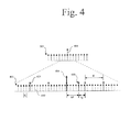
- FIG. 4 illustrates a magnified diagram of a portion 401 of the frequency band 301 searched by the wireless communication device 200 according to an exemplary embodiment of the disclosure.
- a plurality of OFDM (orthogonal frequency division multiplexing) sub carriers 450 associated with the base station are uniformly distributed within the portion 401 , and are separated from one another by a distance ⁇ c .
- the sub carrier separation ⁇ c remains constant within the portion 401 , but may vary among radio access technologies. For purposes of this discussion, ⁇ c is 15 kHz, in accordance with LTE standards.
- the radio module 210 has its center frequency 404 tuned to one of the raster points 401 within the portion, whereas the base station has a carrier frequency 460 located some frequency ⁇ F away from the center frequency 404 of the radio module 210 and a frequency ⁇ f away from a nearest raster point 401 .
- the wireless communication device 200 obtains the fractional frequency ⁇ FFO using the well-known CP (cyclic prefix) correlation method.
- the integer frequency offset IFO PASS cannot be obtained in this manner. Therefore, the controller module 220 must hypothesize the integer frequency offset IFO PASS .
- the controller module In order to obtain the integer frequency offset IFO PASS , the controller module first generates a list of OFDM sub carrier positions with respect to the tuned center frequency of the receiver module 210 that correspond to each raster point 425 along with maximum frequency uncertainty of receiver module within the search band 301 , with respect to the center raster point (corresponding to the receiver carrier frequency). The controller module 220 then determines the integer frequency offset IFO PASS by determining at which of the listed OFDM sub carrier positions the cell is detected.
- the controller module 220 first generates a raster index relative to the center raster point, using the following equation:
- rsidx - ⁇ ⁇ jump 2 * ⁇ raster ⁇ : ⁇ ⁇ jump 2 * ⁇ raster ⁇ , ( 3 )
- ⁇ raster is the frequency spacing between adjacent raster points (e.g., 100 kHz).
- the raster index generated for the example of FIG. 4 will be [ ⁇ 2, ⁇ 1, 0, 1, 2], indicative of the five raster values contained within the search band.
- the list of carrier positions relative to the center raster point can then be determined by applying the following equation to each of the values within the raster index rsidx:
- crlist [ ⁇ 13, ⁇ 7, 0, 7, 13] for the above example, which corresponds to the carrier positions relative to the center raster point at which the base station may be centered is generated.
- the controller module 220 searches each one of the carriers corresponding to the positions within the crlist for the base station, and sets the carrier position corresponding to the location of the base station as the integer frequency offset IFO PASS .
- IFO PASS will be 7 corresponding to the carrier position of the raster point closest to the carrier 460 of the base station.
- the controller module 220 can then determine the raster point index of the base station (RP BS ) and the radio module clock correction factor ( ⁇ ppm ), as follows:
- RP BS round ⁇ ( IFO PASS * ⁇ c ⁇ raster )
- ⁇ ppm ⁇ ⁇ ⁇ f * ⁇ ⁇ ⁇ c RFF req , ( 6 ) where RFFreq corresponds to the current center frequency of the radio module 210 in MHz. It should be noted that equation (5) can be modified to account for oscillator instability.
- equation (5) can be modified to round (IFO PASS * ⁇ c / ⁇ raster ) ⁇ FOMax , and (IFO PASS * ⁇ c / ⁇ raster )+ ⁇ FOMax . In this manner, oscillator instability can be accounted for.
- the controller module 220 must first calculate ⁇ f. This can be done by applying the determined fractional frequency offset ⁇ FFO , the integer frequency offset IFO PASS , and the calculated raster point index of the base station RP BS to the following equations:
- the radio module clock correction factor ⁇ ppm can be determined based on equation (6).
- the wireless communication device 200 is able to pinpoint the center frequency of a base station found with a search band, and can adjust the settings of its radio module 210 .
- FIG. 5 illustrates a block diagram of a method of performing an optimized network search based on stored cell information that may be implemented by the wireless communication device according to an exemplary embodiment of the disclosure.
- the method begins with the wireless communication device making a determination as to whether location information is available ( 510 ). If no location information of the wireless communication device is available, the wireless communication device sorts all cells stored within a memory of the wireless communication device ( 520 ). The sorting may be performed based on one or more of estimated distance from the cell to the wireless communication device, the last time the cell was used, average RSRP (reference signal received power), average RSRQ (reference signal received quality), RAT capabilities, and/or QoS (quality of service) parameters of the cell.
- the wireless communication device searches each of the cells in sorted order until a viable cell is found. Once a cell is found, the method ends ( 590 ).
- the wireless communication device determines that location information is available ( 510 )
- the wireless communication device then scans its memory for cells that are within a vicinity of the location information ( 540 ). If the memory scan reveals only a single stored cell within the vicinity of the location ( 550 ), then the wireless communication device selects and searches the stored cell ( 560 ). The method then ends ( 590 ).
- the wireless communication device then proceeds to sort the cells identified as being within the vicinity of the location ( 570 ). Once sorted, the wireless communication device searches each cell in sorted order until a viable cell is found ( 580 ). Once a cell is found, the method ends ( 590 ).
- the wireless communication device determines that there are no stored cells, or determines that there are no viable cells among the stored cells, the wireless communication device initiates a full search, as discussed below.
- FIG. 6 illustrates a block diagram of a method for performing a multi-RAT network search that may be implemented by the wireless communication device according to an exemplary embodiment of the present invention.
- the method begins with the wireless communication device setting its radio module to have a center frequency CF and bandwidth BW.
- the bandwidth may be set in any one of multiple different ways so as to capture the various RATs ( 610 ).
- the wireless communication device converts signals received within the search band from analog to digital signal ( 620 ).
- the wireless communication device extracts the signals from each RAT via digitally mixing and filtering the digital signals ( 630 - 650 ). Once each of the individual RAT's signals has been extracted, the wireless communication device then searches each individual RAT based on the extracted information ( 660 - 680 ). In order to even further streamline searching of the individual RATs, the wireless communication device can use information obtained during the search of one or more earlier-searched RATs to aid the search of the current RAT. Such information may include frequency offset, advertised neighbor frequency and cell IDs, location information, etc. The RATs can be searched in this manner until one or more viable cells have been discovered, at which point the method ends ( 690 ).
- FIG. 7 illustrates a block diagram of a method for locating 4G base stations within a frequency band that may be implemented by the wireless communication device according to an exemplary embodiment.
- the method begins with the wireless communication device setting its radio module to have a center frequency and bandwidth so as to receive a search band at the start of the 4G frequency band ( 710 ). Once the search band has been set, the wireless communication detects whether a PSS (primary synchronization signal) is found within the search band ( 720 ). Based on detection of the PSS, the wireless communication device determines whether a base station is located within the search band ( 730 ).
- PSS primary synchronization signal
- the wireless communication device determines whether any of the 4G band remains ( 740 ). In other words, the wireless communication device determines whether it has reached the end of the 4G band. If it has ( 740 ), the method ends ( 790 ). Alternatively, if it is determined that there is 4G band remaining ( 740 ), the wireless communication device increments the center frequency of its radio module by ⁇ jump in order to create a new search band ( 750 ). The wireless communication device then repeats this process ( 720 - 750 ) until a base station is found ( 730 ) or the 4G band ends ( 740 ).
- the wireless communication device determines whether 4G band remains ( 770 ). If no band remains, then the method ends ( 790 ). If band does remain, then the wireless communication device increments the center frequency of its radio module by ⁇ BW ( 780 ) in order to generate a new search band. The wireless communication device repeats this process ( 720 , 730 , and 760 - 780 ) until the 4G band ends ( 770 ) or no base station is found within the search band ( 730 ).
- FIG. 8 illustrates a block diagram of a method for determining base station parameters and adjusting a radio module of the wireless communication device that may be implemented by the wireless communication device according to an exemplary embodiment of the present disclosure.
- the method begins with the wireless communication device obtaining the fractional frequency offset ⁇ FFO and the integer frequency offset IFO PASS ( 810 ).
- the fractional frequency offset ⁇ FFO may be obtained using CP correlation
- the integer frequency offset IFO PASS may be obtained by determining the position of the center frequency of the base station relative to the radio module's center frequency.
- the wireless communication device determines ⁇ f based on those values ( 820 ) using equations (7)-(9), above. Using the calculated ⁇ f, the wireless communication device calculates a clock correction factor for the radio module ( 830 ) using equation (6), above, or some suitable variation thereof.
- the wireless communication device then calculates an updated center frequency and an updated clock frequency for the radio module 840 using equations (10) and (11), above, or some suitable variation(s) thereof, after which the method ends ( 850 ).
Landscapes
- Engineering & Computer Science (AREA)
- Computer Networks & Wireless Communication (AREA)
- Signal Processing (AREA)
- Computer Security & Cryptography (AREA)
- Mobile Radio Communication Systems (AREA)
Abstract
Description
where BWfound corresponds to the bandwidth found from broadcast information corresponding to the found base station, BWgiven corresponds to bandwidth information given by the higher layer prior to starting the network search, and BWmin corresponds to the minimum bandwidth as set by the 4G standard (1.4 MHz).
CF new =CF old+ΔBS+ΔBW, (2)
where CFnew corresponds to the new center frequency of the
where Δraster is the frequency spacing between adjacent raster points (e.g., 100 kHz). Using equation (3), the raster index generated for the example of
where RFFreq corresponds to the current center frequency of the
RFFrequpdated =RFFreq*(1+εppm*1e −6) (10)
ClockFrequpdated=ClockFreq*(1+εppm*1e −6), (11)
where RFFrequpdated is the updated center frequency of the
Claims (20)
Priority Applications (6)
| Application Number | Priority Date | Filing Date | Title |
|---|---|---|---|
| US13/341,627 US8868110B2 (en) | 2011-11-21 | 2011-12-30 | Wireless communication device capable of efficient network search |
| EP12005728.6A EP2595427A2 (en) | 2011-11-21 | 2012-08-07 | Wireless Communication device capable of efficient network search |
| TW101133327A TWI478601B (en) | 2011-11-21 | 2012-09-12 | Wireless communication device capable of efficient network search |
| KR1020120102616A KR101460055B1 (en) | 2011-11-21 | 2012-09-17 | Wireless communication device capable of efficient network search |
| CN2012104762471A CN103139873A (en) | 2011-11-21 | 2012-11-21 | Wireless communication device capable of efficient network search |
| US14/511,466 US20150024791A1 (en) | 2011-11-21 | 2014-10-10 | Wireless Communication Device Capable of Efficient Network Search |
Applications Claiming Priority (2)
| Application Number | Priority Date | Filing Date | Title |
|---|---|---|---|
| US201161562196P | 2011-11-21 | 2011-11-21 | |
| US13/341,627 US8868110B2 (en) | 2011-11-21 | 2011-12-30 | Wireless communication device capable of efficient network search |
Related Child Applications (1)
| Application Number | Title | Priority Date | Filing Date |
|---|---|---|---|
| US14/511,466 Division US20150024791A1 (en) | 2011-11-21 | 2014-10-10 | Wireless Communication Device Capable of Efficient Network Search |
Publications (2)
| Publication Number | Publication Date |
|---|---|
| US20130130724A1 US20130130724A1 (en) | 2013-05-23 |
| US8868110B2 true US8868110B2 (en) | 2014-10-21 |
Family
ID=46796222
Family Applications (2)
| Application Number | Title | Priority Date | Filing Date |
|---|---|---|---|
| US13/341,627 Expired - Fee Related US8868110B2 (en) | 2011-11-21 | 2011-12-30 | Wireless communication device capable of efficient network search |
| US14/511,466 Abandoned US20150024791A1 (en) | 2011-11-21 | 2014-10-10 | Wireless Communication Device Capable of Efficient Network Search |
Family Applications After (1)
| Application Number | Title | Priority Date | Filing Date |
|---|---|---|---|
| US14/511,466 Abandoned US20150024791A1 (en) | 2011-11-21 | 2014-10-10 | Wireless Communication Device Capable of Efficient Network Search |
Country Status (5)
| Country | Link |
|---|---|
| US (2) | US8868110B2 (en) |
| EP (1) | EP2595427A2 (en) |
| KR (1) | KR101460055B1 (en) |
| CN (1) | CN103139873A (en) |
| TW (1) | TWI478601B (en) |
Cited By (3)
| Publication number | Priority date | Publication date | Assignee | Title |
|---|---|---|---|---|
| US20150024791A1 (en) * | 2011-11-21 | 2015-01-22 | Broadcom Corporation | Wireless Communication Device Capable of Efficient Network Search |
| US10805893B2 (en) | 2016-08-19 | 2020-10-13 | Samsung Electronics Co., Ltd | System and method for providing universal synchronization signals for new radio |
| US20220046641A1 (en) * | 2020-08-05 | 2022-02-10 | Apple Inc. | Systems, apparatus, and methods for indicating spectrum sharing |
Families Citing this family (52)
| Publication number | Priority date | Publication date | Assignee | Title |
|---|---|---|---|---|
| US10154448B2 (en) * | 2014-04-04 | 2018-12-11 | Mstar Semiconductor, Inc. | Multimode mobile communication network search in a wireless communication device |
| US20160050663A1 (en) * | 2014-08-15 | 2016-02-18 | Aviacomm Inc. | System and method for increasing data rate of commercial cellular communication systems with scattered spectrum |
| CN105704783B (en) * | 2014-11-24 | 2019-06-14 | 中国移动通信集团公司 | A frequency sweep interval determination and terminal frequency sweep method, device and terminal |
| ES2693980T3 (en) | 2014-12-01 | 2018-12-17 | Telefonaktiebolaget Lm Ericsson (Publ) | Procedures for connection and cell search in a cellular communication device |
| EP3361793B1 (en) * | 2015-11-06 | 2021-03-03 | Huawei Technologies Co., Ltd. | Frequency determining method and device |
| US10181826B2 (en) | 2017-04-25 | 2019-01-15 | Qorvo Us, Inc. | Envelope tracking amplifier circuit |
| US10455485B2 (en) * | 2017-04-28 | 2019-10-22 | Qualcomm Incorporated | Method and apparatus for frequency scan in Narrow Band—Internet of Things (NB-IoT) systems |
| US10158330B1 (en) | 2017-07-17 | 2018-12-18 | Qorvo Us, Inc. | Multi-mode envelope tracking amplifier circuit |
| CN111491381B (en) * | 2017-08-10 | 2021-05-18 | 华为技术有限公司 | Transmitting apparatus, receiving apparatus and method thereof |
| US10326490B2 (en) * | 2017-08-31 | 2019-06-18 | Qorvo Us, Inc. | Multi radio access technology power management circuit |
| US10680559B2 (en) | 2017-10-06 | 2020-06-09 | Qorvo Us, Inc. | Envelope tracking system for transmitting a wide modulation bandwidth signal(s) |
| CN110034891B (en) * | 2018-01-12 | 2020-10-20 | 电信科学技术研究院有限公司 | System information configuration method and device |
| US10439557B2 (en) | 2018-01-15 | 2019-10-08 | Qorvo Us, Inc. | Envelope tracking power management circuit |
| US10637408B2 (en) | 2018-01-18 | 2020-04-28 | Qorvo Us, Inc. | Envelope tracking voltage tracker circuit and related power management circuit |
| US10742170B2 (en) | 2018-02-01 | 2020-08-11 | Qorvo Us, Inc. | Envelope tracking circuit and related power amplifier system |
| US10944365B2 (en) | 2018-06-28 | 2021-03-09 | Qorvo Us, Inc. | Envelope tracking amplifier circuit |
| US11570701B2 (en) | 2018-07-13 | 2023-01-31 | Huawei Technologies Co., Ltd. | Method for selecting NSA and SA networking mode, and terminal device |
| US11088618B2 (en) | 2018-09-05 | 2021-08-10 | Qorvo Us, Inc. | PWM DC-DC converter with linear voltage regulator for DC assist |
| US10911001B2 (en) | 2018-10-02 | 2021-02-02 | Qorvo Us, Inc. | Envelope tracking amplifier circuit |
| US11018638B2 (en) | 2018-10-31 | 2021-05-25 | Qorvo Us, Inc. | Multimode envelope tracking circuit and related apparatus |
| US10985702B2 (en) | 2018-10-31 | 2021-04-20 | Qorvo Us, Inc. | Envelope tracking system |
| US10938351B2 (en) | 2018-10-31 | 2021-03-02 | Qorvo Us, Inc. | Envelope tracking system |
| US10680556B2 (en) | 2018-11-05 | 2020-06-09 | Qorvo Us, Inc. | Radio frequency front-end circuit |
| US11031909B2 (en) | 2018-12-04 | 2021-06-08 | Qorvo Us, Inc. | Group delay optimization circuit and related apparatus |
| US11082007B2 (en) | 2018-12-19 | 2021-08-03 | Qorvo Us, Inc. | Envelope tracking integrated circuit and related apparatus |
| US11146213B2 (en) | 2019-01-15 | 2021-10-12 | Qorvo Us, Inc. | Multi-radio access technology envelope tracking amplifier apparatus |
| US11025458B2 (en) | 2019-02-07 | 2021-06-01 | Qorvo Us, Inc. | Adaptive frequency equalizer for wide modulation bandwidth envelope tracking |
| US10998859B2 (en) | 2019-02-07 | 2021-05-04 | Qorvo Us, Inc. | Dual-input envelope tracking integrated circuit and related apparatus |
| US11233481B2 (en) | 2019-02-18 | 2022-01-25 | Qorvo Us, Inc. | Modulated power apparatus |
| US11374482B2 (en) | 2019-04-02 | 2022-06-28 | Qorvo Us, Inc. | Dual-modulation power management circuit |
| US11082009B2 (en) | 2019-04-12 | 2021-08-03 | Qorvo Us, Inc. | Envelope tracking power amplifier apparatus |
| US11018627B2 (en) | 2019-04-17 | 2021-05-25 | Qorvo Us, Inc. | Multi-bandwidth envelope tracking integrated circuit and related apparatus |
| US11424719B2 (en) | 2019-04-18 | 2022-08-23 | Qorvo Us, Inc. | Multi-bandwidth envelope tracking integrated circuit |
| US11031911B2 (en) | 2019-05-02 | 2021-06-08 | Qorvo Us, Inc. | Envelope tracking integrated circuit and related apparatus |
| US11349436B2 (en) | 2019-05-30 | 2022-05-31 | Qorvo Us, Inc. | Envelope tracking integrated circuit |
| US11539289B2 (en) | 2019-08-02 | 2022-12-27 | Qorvo Us, Inc. | Multi-level charge pump circuit |
| US11309922B2 (en) | 2019-12-13 | 2022-04-19 | Qorvo Us, Inc. | Multi-mode power management integrated circuit in a small formfactor wireless apparatus |
| US11349513B2 (en) | 2019-12-20 | 2022-05-31 | Qorvo Us, Inc. | Envelope tracking system |
| US11539330B2 (en) | 2020-01-17 | 2022-12-27 | Qorvo Us, Inc. | Envelope tracking integrated circuit supporting multiple types of power amplifiers |
| US11716057B2 (en) | 2020-01-28 | 2023-08-01 | Qorvo Us, Inc. | Envelope tracking circuitry |
| US11728774B2 (en) | 2020-02-26 | 2023-08-15 | Qorvo Us, Inc. | Average power tracking power management integrated circuit |
| CN111405627A (en) * | 2020-03-20 | 2020-07-10 | 珠海市魅族科技有限公司 | Network switching method and device of mobile terminal, electronic equipment and storage medium |
| US11196392B2 (en) | 2020-03-30 | 2021-12-07 | Qorvo Us, Inc. | Device and device protection system |
| US11588449B2 (en) | 2020-09-25 | 2023-02-21 | Qorvo Us, Inc. | Envelope tracking power amplifier apparatus |
| US11728796B2 (en) | 2020-10-14 | 2023-08-15 | Qorvo Us, Inc. | Inverted group delay circuit |
| US11909385B2 (en) | 2020-10-19 | 2024-02-20 | Qorvo Us, Inc. | Fast-switching power management circuit and related apparatus |
| CN114513750B (en) * | 2020-11-16 | 2024-02-23 | 福建星网元智科技有限公司 | Price tag searching method and storage device |
| EP4475434A2 (en) | 2020-12-22 | 2024-12-11 | Qorvo US, Inc. | Power management apparatus operable with multiple configurations |
| US12068720B2 (en) | 2021-02-26 | 2024-08-20 | Qorvo Us, Inc. | Barely Doherty dual envelope tracking (BD2E) circuit |
| US12212286B2 (en) | 2021-03-05 | 2025-01-28 | Qorvo Us, Inc. | Complementary envelope detector |
| US12126305B2 (en) | 2021-05-27 | 2024-10-22 | Qorvo Us, Inc. | Radio frequency (RF) equalizer in an envelope tracking (ET) circuit |
| US12063018B2 (en) | 2021-06-10 | 2024-08-13 | Qorvo Us, Inc. | Envelope tracking integrated circuit operable with multiple types of power amplifiers |
Citations (6)
| Publication number | Priority date | Publication date | Assignee | Title |
|---|---|---|---|---|
| US20070237261A1 (en) | 2006-04-06 | 2007-10-11 | Bengt Lindoff | Apparatus and method for efficient inter radio access technology operation |
| KR20100055435A (en) | 2007-08-17 | 2010-05-26 | 가부시키가이샤 엔티티 도코모 | User equipment and wireless communication system |
| US20110098074A1 (en) | 2008-10-30 | 2011-04-28 | Dong Youn Seo | Method for wireless communication between user equipment and base station in wireless communication system supporting first user equipment that uses single frequency band and second user equipment that uses plurality of frequency bands |
| US8059731B2 (en) * | 2005-06-14 | 2011-11-15 | Ntt Docomo, Inc. | Base station, mobile station and method |
| US8068834B2 (en) * | 2002-08-27 | 2011-11-29 | Qualcomm Incorporated | Intra-frequency, inter-frequency and inter-radio access technology searching for neighbor cells within a fixed time duration |
| US20120034917A1 (en) * | 2009-04-20 | 2012-02-09 | Tekefonaktiebolaget LM Ericsson (publ) | Method Of Frequency Search |
Family Cites Families (8)
| Publication number | Priority date | Publication date | Assignee | Title |
|---|---|---|---|---|
| US8676226B2 (en) * | 2009-07-09 | 2014-03-18 | Htc Corporation | Method of handling location service and related communication device |
| US9220055B2 (en) * | 2009-10-23 | 2015-12-22 | Samsung Electronics Co., Ltd | Methods and apparatus for cell selection/reselection of a mobile terminal from a legacy network to an advanced network |
| KR101313105B1 (en) * | 2009-12-16 | 2013-09-30 | 한국전자통신연구원 | mobile communication system and cell reselection method thereof |
| WO2012021097A2 (en) * | 2010-08-11 | 2012-02-16 | Telefonaktiebolaget L M Ericsson (Publ) | Methods of providing cell grouping for positioning and related networks and devices |
| US9066262B2 (en) * | 2010-09-30 | 2015-06-23 | Telefonaktiebolaget L M Ericsson (Publ) | Methods and nodes for handling measurements |
| KR101946594B1 (en) * | 2011-07-12 | 2019-02-11 | 인터디지탈 패튼 홀딩스, 인크 | Method and apparatus for multi-rat access mode operation |
| US8868110B2 (en) * | 2011-11-21 | 2014-10-21 | Broadcom Corporation | Wireless communication device capable of efficient network search |
| US9544105B2 (en) * | 2012-05-14 | 2017-01-10 | Telefonaktiebolaget Lm Ericsson (Publ) | Enhanced receiver adaptation based on relation between signals from aggressor and victim cells |
-
2011
- 2011-12-30 US US13/341,627 patent/US8868110B2/en not_active Expired - Fee Related
-
2012
- 2012-08-07 EP EP12005728.6A patent/EP2595427A2/en not_active Withdrawn
- 2012-09-12 TW TW101133327A patent/TWI478601B/en not_active IP Right Cessation
- 2012-09-17 KR KR1020120102616A patent/KR101460055B1/en not_active IP Right Cessation
- 2012-11-21 CN CN2012104762471A patent/CN103139873A/en active Pending
-
2014
- 2014-10-10 US US14/511,466 patent/US20150024791A1/en not_active Abandoned
Patent Citations (8)
| Publication number | Priority date | Publication date | Assignee | Title |
|---|---|---|---|---|
| US8068834B2 (en) * | 2002-08-27 | 2011-11-29 | Qualcomm Incorporated | Intra-frequency, inter-frequency and inter-radio access technology searching for neighbor cells within a fixed time duration |
| US8059731B2 (en) * | 2005-06-14 | 2011-11-15 | Ntt Docomo, Inc. | Base station, mobile station and method |
| US8243839B2 (en) * | 2005-06-14 | 2012-08-14 | Ntt Docomo, Inc. | Base station, mobile station and method |
| US20070237261A1 (en) | 2006-04-06 | 2007-10-11 | Bengt Lindoff | Apparatus and method for efficient inter radio access technology operation |
| KR20100055435A (en) | 2007-08-17 | 2010-05-26 | 가부시키가이샤 엔티티 도코모 | User equipment and wireless communication system |
| US8170548B2 (en) | 2007-08-17 | 2012-05-01 | Ntt Docomo, Inc. | User equipment terminal and radio communication system |
| US20110098074A1 (en) | 2008-10-30 | 2011-04-28 | Dong Youn Seo | Method for wireless communication between user equipment and base station in wireless communication system supporting first user equipment that uses single frequency band and second user equipment that uses plurality of frequency bands |
| US20120034917A1 (en) * | 2009-04-20 | 2012-02-09 | Tekefonaktiebolaget LM Ericsson (publ) | Method Of Frequency Search |
Non-Patent Citations (2)
| Title |
|---|
| Office Action directed toward related Korean Patent Application No. KR 10-2012-0102616, dated Mar. 11, 2014, from the Korean Patent Office; 4 pages. |
| Office Action for Taiwanese Patent Application No. 10320682420, mailed on May 21, 2014. |
Cited By (6)
| Publication number | Priority date | Publication date | Assignee | Title |
|---|---|---|---|---|
| US20150024791A1 (en) * | 2011-11-21 | 2015-01-22 | Broadcom Corporation | Wireless Communication Device Capable of Efficient Network Search |
| US10805893B2 (en) | 2016-08-19 | 2020-10-13 | Samsung Electronics Co., Ltd | System and method for providing universal synchronization signals for new radio |
| US11558837B2 (en) | 2016-08-19 | 2023-01-17 | Samsung Electronics Co., Ltd | System and method for providing universal synchronization signals for new radio |
| US20220046641A1 (en) * | 2020-08-05 | 2022-02-10 | Apple Inc. | Systems, apparatus, and methods for indicating spectrum sharing |
| US11516804B2 (en) * | 2020-08-05 | 2022-11-29 | Apple Inc. | Systems, apparatus, and methods for indicating spectrum sharing |
| US11832232B2 (en) | 2020-08-05 | 2023-11-28 | Apple Inc. | Systems, apparatus, and methods for indicating spectrum sharing |
Also Published As
| Publication number | Publication date |
|---|---|
| US20150024791A1 (en) | 2015-01-22 |
| TW201322794A (en) | 2013-06-01 |
| CN103139873A (en) | 2013-06-05 |
| KR101460055B1 (en) | 2014-11-11 |
| US20130130724A1 (en) | 2013-05-23 |
| EP2595427A2 (en) | 2013-05-22 |
| KR20130056163A (en) | 2013-05-29 |
| TWI478601B (en) | 2015-03-21 |
Similar Documents
| Publication | Publication Date | Title |
|---|---|---|
| US8868110B2 (en) | Wireless communication device capable of efficient network search | |
| US8938239B2 (en) | Wireless communication device capable of efficient handoffs | |
| CN113383581B (en) | Method for updating system information and wireless transmitting/receiving unit using the method | |
| US7092353B2 (en) | Carrier search methods and apparatus | |
| US7657261B2 (en) | Technique for using the same wireless frequency channel in overlapping or adjacent coverage areas | |
| US9668094B2 (en) | Utilizing Wi-Fi country code to assist cellular network selection | |
| US7013140B2 (en) | Mobile terminals and methods for performing fast initial frequency scans and cell searches | |
| JP3851525B2 (en) | Mobile station apparatus, mobile communication system, and carrier detection method | |
| US10285156B2 (en) | Dynamic measurement gap configuration for inter-frequency positioning measurements | |
| US9113399B2 (en) | Method for searching for a radio cell and mobile terminal | |
| EP2632206B1 (en) | Parallel Multi-Rat PLMN Search | |
| US9490935B2 (en) | Blind search for network positioning reference signal (PRS) configuration parameters | |
| JP2009514454A (en) | Seamless inter-frequency handoff in wireless communication networks | |
| KR20090025259A (en) | System and method of performing cell measurements in a telecommunications system | |
| US20140355596A1 (en) | Method, Apparatus and Computer Program for Search and Synchronisation | |
| CN103634815A (en) | Communication device and method for detecting a radio signal | |
| JP5457545B2 (en) | Mobile communication system, cell selection method, base station apparatus, and mobile station apparatus | |
| US9629110B2 (en) | Wireless communication apparatus and method performing signal scanning to determine the strongest signal useable for stabilizing a local oscillator |
Legal Events
| Date | Code | Title | Description |
|---|---|---|---|
| AS | Assignment |
Owner name: BROADCOM CORPORATION, CALIFORNIA Free format text: ASSIGNMENT OF ASSIGNORS INTEREST;ASSIGNORS:KUMAR REDDY, C. ASHOK;MOOKHERJE, ABIR;VUMMINTALA, SHASHIDHAR;REEL/FRAME:027466/0846 Effective date: 20111229 |
|
| AS | Assignment |
Owner name: TATA STEEL NEDERLAND TECHNOLOGY BV, NETHERLANDS Free format text: ASSIGNMENT OF ASSIGNORS INTEREST;ASSIGNOR:CELOTTO, STEVEN;REEL/FRAME:028652/0343 Effective date: 20120716 |
|
| AS | Assignment |
Owner name: TATA STEEL NEDERLAND TECHNOLOGY BV, NETHERLANDS Free format text: CORRECTIVE ASSIGNMENT TO CORRECT THE TITLE OF THE INVENTION AND THE ASSIGNEE'S ADDRESS PREVIOUSLY RECORDED ON REEL 028652 FRAME 0343. ASSIGNOR(S) HEREBY CONFIRMS THE CORRECT TITLE INDICATED ON ASSIGNMENT AND ADDRESS IS P.O. BOX 10000;ASSIGNOR:CELOTTO, STEVEN;REEL/FRAME:028708/0304 Effective date: 20120716 |
|
| CC | Certificate of correction | ||
| AS | Assignment |
Owner name: BANK OF AMERICA, N.A., AS COLLATERAL AGENT, NORTH CAROLINA Free format text: PATENT SECURITY AGREEMENT;ASSIGNOR:BROADCOM CORPORATION;REEL/FRAME:037806/0001 Effective date: 20160201 Owner name: BANK OF AMERICA, N.A., AS COLLATERAL AGENT, NORTH Free format text: PATENT SECURITY AGREEMENT;ASSIGNOR:BROADCOM CORPORATION;REEL/FRAME:037806/0001 Effective date: 20160201 |
|
| AS | Assignment |
Owner name: AVAGO TECHNOLOGIES GENERAL IP (SINGAPORE) PTE. LTD., SINGAPORE Free format text: ASSIGNMENT OF ASSIGNORS INTEREST;ASSIGNOR:BROADCOM CORPORATION;REEL/FRAME:041706/0001 Effective date: 20170120 Owner name: AVAGO TECHNOLOGIES GENERAL IP (SINGAPORE) PTE. LTD Free format text: ASSIGNMENT OF ASSIGNORS INTEREST;ASSIGNOR:BROADCOM CORPORATION;REEL/FRAME:041706/0001 Effective date: 20170120 |
|
| AS | Assignment |
Owner name: BROADCOM CORPORATION, CALIFORNIA Free format text: TERMINATION AND RELEASE OF SECURITY INTEREST IN PATENTS;ASSIGNOR:BANK OF AMERICA, N.A., AS COLLATERAL AGENT;REEL/FRAME:041712/0001 Effective date: 20170119 |
|
| FEPP | Fee payment procedure |
Free format text: MAINTENANCE FEE REMINDER MAILED (ORIGINAL EVENT CODE: REM.) |
|
| AS | Assignment |
Owner name: AVAGO TECHNOLOGIES INTERNATIONAL SALES PTE. LIMITE Free format text: MERGER;ASSIGNOR:AVAGO TECHNOLOGIES GENERAL IP (SINGAPORE) PTE. LTD.;REEL/FRAME:047642/0417 Effective date: 20180509 |
|
| LAPS | Lapse for failure to pay maintenance fees |
Free format text: PATENT EXPIRED FOR FAILURE TO PAY MAINTENANCE FEES (ORIGINAL EVENT CODE: EXP.); ENTITY STATUS OF PATENT OWNER: LARGE ENTITY |
|
| STCH | Information on status: patent discontinuation |
Free format text: PATENT EXPIRED DUE TO NONPAYMENT OF MAINTENANCE FEES UNDER 37 CFR 1.362 |
|
| FP | Lapsed due to failure to pay maintenance fee |
Effective date: 20181021 |
|
| AS | Assignment |
Owner name: AVAGO TECHNOLOGIES INTERNATIONAL SALES PTE. LIMITE Free format text: CORRECTIVE ASSIGNMENT TO CORRECT THE EXECUTION DATE OF THE MERGER PREVIOUSLY RECORDED ON REEL 047642 FRAME 0417. ASSIGNOR(S) HEREBY CONFIRMS THE ASSIGNMENT,;ASSIGNOR:AVAGO TECHNOLOGIES GENERAL IP (SINGAPORE) PTE. LTD.;REEL/FRAME:048521/0395 Effective date: 20180905 |