US8744150B2 - Method for determining a layer orientation for a 2D layer image - Google Patents
Method for determining a layer orientation for a 2D layer image Download PDFInfo
- Publication number
- US8744150B2 US8744150B2 US13/450,701 US201213450701A US8744150B2 US 8744150 B2 US8744150 B2 US 8744150B2 US 201213450701 A US201213450701 A US 201213450701A US 8744150 B2 US8744150 B2 US 8744150B2
- Authority
- US
- United States
- Prior art keywords
- model
- image data
- layer
- orientation
- patient
- Prior art date
- Legal status (The legal status is an assumption and is not a legal conclusion. Google has not performed a legal analysis and makes no representation as to the accuracy of the status listed.)
- Active, expires
Links
Images


Classifications
-
- A—HUMAN NECESSITIES
- A61—MEDICAL OR VETERINARY SCIENCE; HYGIENE
- A61B—DIAGNOSIS; SURGERY; IDENTIFICATION
- A61B6/00—Apparatus or devices for radiation diagnosis; Apparatus or devices for radiation diagnosis combined with radiation therapy equipment
- A61B6/50—Apparatus or devices for radiation diagnosis; Apparatus or devices for radiation diagnosis combined with radiation therapy equipment specially adapted for specific body parts; specially adapted for specific clinical applications
- A61B6/505—Apparatus or devices for radiation diagnosis; Apparatus or devices for radiation diagnosis combined with radiation therapy equipment specially adapted for specific body parts; specially adapted for specific clinical applications for diagnosis of bone
-
- A—HUMAN NECESSITIES
- A61—MEDICAL OR VETERINARY SCIENCE; HYGIENE
- A61B—DIAGNOSIS; SURGERY; IDENTIFICATION
- A61B6/00—Apparatus or devices for radiation diagnosis; Apparatus or devices for radiation diagnosis combined with radiation therapy equipment
- A61B6/52—Devices using data or image processing specially adapted for radiation diagnosis
- A61B6/5211—Devices using data or image processing specially adapted for radiation diagnosis involving processing of medical diagnostic data
- A61B6/5223—Devices using data or image processing specially adapted for radiation diagnosis involving processing of medical diagnostic data generating planar views from image data, e.g. extracting a coronal view from a 3D image
-
- A—HUMAN NECESSITIES
- A61—MEDICAL OR VETERINARY SCIENCE; HYGIENE
- A61B—DIAGNOSIS; SURGERY; IDENTIFICATION
- A61B6/00—Apparatus or devices for radiation diagnosis; Apparatus or devices for radiation diagnosis combined with radiation therapy equipment
- A61B6/52—Devices using data or image processing specially adapted for radiation diagnosis
- A61B6/5211—Devices using data or image processing specially adapted for radiation diagnosis involving processing of medical diagnostic data
- A61B6/5229—Devices using data or image processing specially adapted for radiation diagnosis involving processing of medical diagnostic data combining image data of a patient, e.g. combining a functional image with an anatomical image
-
- A—HUMAN NECESSITIES
- A61—MEDICAL OR VETERINARY SCIENCE; HYGIENE
- A61B—DIAGNOSIS; SURGERY; IDENTIFICATION
- A61B6/00—Apparatus or devices for radiation diagnosis; Apparatus or devices for radiation diagnosis combined with radiation therapy equipment
- A61B6/02—Arrangements for diagnosis sequentially in different planes; Stereoscopic radiation diagnosis
- A61B6/03—Computed tomography [CT]
- A61B6/032—Transmission computed tomography [CT]
Definitions
- the invention relates to a method for determining a layer orientation for a 2D layer image that is to be generated from 3D image data of an anatomical object in a patient's body.
- 3D image data is/are increasingly being generated in the field of medical imaging for 3-dimensionally imaging a respective anatomical object in the patient's body.
- anatomical objects include organs, bones, and joints in the patient's body.
- 3D image data is usually visualized in the form of 2D layer images.
- Multiplanar reformatting (MPR) is an instance of what is known.
- Layers of a 3D data record are here displayed as 2D layer images, with the layer orientation being defined—at least in the case of planar layers or locally—by a projection direction perpendicular to the layer.
- the layer which is also to take a curved course, for example.
- the required or, as the case may be, correct layer orientation is produced automatically in the image data: That is possible because the patient always lies in a defined position in the recording device when the 3D image data is being recorded.
- the image data or, as the case may be, the object being imaged therefore has a defined spatial position or, as the case may be, orientation in a given coordinate system of the 3D image data.
- Intraoperative applications for generating 3D image data such as, for instance, 3D C-arc imaging are, though, also known.
- the initial situation is different here as there is broad scope for freely selecting the patient's respective position relative to the imaging system.
- the anatomical object's position or, as the case may be, orientation in the 3D image data is not predefined or, as the case may be, is not comparable or standardized for different recordings.
- an appropriate layer orientation or, as the case may be, imaging direction for example an optimal layer orientation or, as the case may be, default orientation or one specified according to medical standards for certain joints.
- the surgeon or surgical assistant first has to process the intraoperatively recorded 3D image data manually, which is to say as a rule has to turn and move it to determine and present the optimal or, as the case may be, standardized layer orientation or position. That takes extra operating time with possible changing between a sterile and non-sterile area, and it also requires experienced personnel.
- the layer orientation for the 2D layer images is here established by hand based on a subjective consideration and assessment of the 3D image data.
- a method for determining a layer orientation for a 2D layer image to be generated from 3D image data of an anatomical object in a body of a patient comprises:
- a model pool a model resembling the anatomical object imaged in the 3D image data, the model having been assigned a default orientation in a permanently selected relative position with respect to the model;
- a real anatomical object in a patient's body has already been imaged or, as the case may be, actually been recorded from the patient in the 3D image data.
- a (virtual) model of the object as closely as possible resembling the object imaged in the 3D image data is first selected from a model pool.
- the relevant model has already been preassigned a default orientation standardized for said model, for example, or one that is optimal or only desired.
- the default orientation is assigned to the model in a permanently selected relative position.
- the relevant default orientation has been established in advance for the model; the default orientation will be turned or moved compliantly when the model is turned or moved so that the same relative position will always be maintained. With the position relative to the default orientation being maintained, the model will then be aligned with the 3D image data. Aligning takes place such that the model will have been matched to the object with maximum coincidence. Thus what is termed a “best-fit” process is carried out. In other words the model will be “fitted” to the actual image of the anatomical object in the 3D image data by moving, rotating, or scaling. It is also conceivable to fit only a part (“partial fitting”) of the—for instance statistical—model to the object, thus to the bone if, say, a part of a joint is broken.
- the default orientation established through moving or rotating the model relative to the—real, imaged—object and hence to the 3D image data is selected as the layer orientation for the 3D image data, so for actually generating the layer image from the object.
- the method according to the invention can be fully automated by means of image-processing algorithms.
- the method offers the advantage that layer orienting or, as the case may be, selecting that corresponds to default orienting is performed for any 3D image data.
- the default (layer) orientations are established on the model in a fixed relative position, are adjusted compliantly during the fitting process, and finally accepted for the real data.
- the result is hence an ensuing representation of the 3D image data in correspondingly desired or optimal directions.
- Determining a layer orientation in a complex manner using the imaged object is replaced by simpler matching of the model to the object followed by automatically establishing the layer orientation. So a complex and possibly error-prone user intervention is no longer required for selecting the layer orientation.
- Valuable theater time can be saved and sources of errors reduced.
- layer selecting and representing MPR layers can be performed fully automatically.
- the inventive method can be used also for methods, such as computed tomography cited above, having per se standardized or, as the case may be, reproducible layer orienting.
- applying the method will make it possible to eliminate, for example, a patient's imprecise or even incorrect positioning in the interests of optimal or, as the case may be, correct layer orienting.
- the consequent advantage lies in no longer having to be so concerned about the patient's being in a particularly rigidly defined position during a relevant CT recording session.
- the patient can be positioned in virtually any way, which will in turn enhance his/her comfort.
- the inventive step is primarily found in that there is employed an object model, for example a bone model, on which standard or, say, default layer orientations have been established once in a complex procedure, and in that there is employed the usually easy-to-perform and less error-prone process of fitting the model to the actually imaged anatomical object.
- an object model for example a bone model, on which standard or, say, default layer orientations have been established once in a complex procedure, and in that there is employed the usually easy-to-perform and less error-prone process of fitting the model to the actually imaged anatomical object.
- the model pool contains at least one model for each of the types of anatomical objects in a patient's body that are of interest.
- a model in the model pool for each human bone and joint and each human organ customarily requiring to be examined.
- the method can indeed be generally applied also to non-rigid objects, for example a patient's liver, the accuracy that can be achieved will be limited in such cases owing to the object's motion.
- a system executing the method will need only to be informed of the specific object imaged in the 3D image data to be able to select the corresponding correct model. That can be done for example interactively by the surgeon performing imaging or by an assistant. The selection can, though, also be made automatically through an image comparison, for example.
- the object is hence a bone structure in the patient's body with the model then being a corresponding model of the bone structure.
- Bone structures, so bones and joints, are as a rule the main target of a corresponding imaging operation.
- the aforementioned method is particularly advantageous especially for bones and also joints because the layer orientations, which is to say projection directions, accordingly requiring to be selected need to have been selected with particular care here so that, for example, reliable diagnoses can be made about, say, the patient's joint functionality.
- the model is a statistically averaged model of the same object in different patients' bodies.
- a multiplicity of different patients' knee joints are statistically averaged in order to produce a standardized averaged knee model.
- the probability that a corresponding knee model can be matched particularly well to the actually imaged anatomical object will then be particularly high.
- Models can, though, alternatively also be used as images of typical patients, for example healthy patients or patients with typical diagnoses.
- an object of an as a rule healthy side of the patient as a mirror-image model for the object of the patient's other, for example injured side. That only requires for there to be an image of the healthy side obtained, for example, from a pre-operative whole-body CT scan.
- the default orientation assigned to the model is a clinically standardized default orientation for the same objects in different patients' bodies.
- Standardized layer orientations for assessing 3D image data offer the advantage that comparable diagnoses for different patients can here be made by different doctors.
- the method will finally also supply standardized layer orientations for generating the 2D layer images.
- FIG. 1 is a schematic sketch of a patient's 3D image data in which an anatomical object is imaged
- FIG. 2 is a schematic sketch of a model that corresponds to the anatomical object and has established default orientations
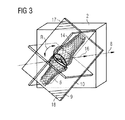
- FIG. 3 is a schematic sketch of the 3 D image data having determined layer orientations.
- 3D image data 2 that has been recorded from a patient 4 , in this case from their knee joint.
- An object 6 namely the knee joint, of the patient 4 is thus imaged in the 3D image data 2 .
- the aim is to determine the relative position of a layer orientation 9 or, as the case may be, projection direction 8 (only indicated in FIG. 1 by an arrow) for 3D image data 2 .
- the determined position will then serve to generate a 2D layer image 10 from 3D image data 2 .
- a model pool 12 It contains in each case one model for each type of object 13 a , 13 b , 13 c generally found in patients' bodies.
- Type 13 a is therein a femur, type 13 b a dorsal vertebra, and type 13 c a knee joint.
- a model 14 of object 6 similar to object 6 is selected from a model pool 12 .
- An imaging direction 16 or, as the case may be, a default orientation 17 perpendicular thereto (in the form of an imaging plane 18 , indicated in FIG. 2 by hatching) has already been pre-established on model 14 or, as the case may be, for each type 13 a - c by way of a complex procedure.
- Default orientation 17 (or, as the case may be, imaging direction 16 ) corresponds here to one of the planes or, as the case may be, layers conforming to the MPR clinical standard that are shown in FIG. 2 for representing knee joints.
- Default orientation 17 occupies a fixed relative position R with respect to model 14 , indicated in FIG. 2 by an arrow.
- Arrow 20 indicates that model 14 is now oriented on 3D image data 2 or, as the case may be, object 6 . That is done in such a way that model 14 will fit as coincidently as possible onto object 6 . Fitting is done by, for example, iteratively turning, moving, and scaling model 14 relative to object 6 in a process performed automatically by an image-processing system.
- FIG. 3 shows the result on completion of optimal matching, meaning with as close as possible a fit.
- imaging direction 16 or, as the case may be, default orientation 17 remains in an unchanged relative position R with respect to model 14 . So in other words, default orientation 17 or, as the case may be, the position of imaging plane 18 is scaled, moved, or rotated together with model 14 relative 3D image data 2 or, as the case may be, object 6 .
- Default orientation 17 is finally selected as layer orientation 9 for 3D image data 2 so that the final result, indicated by imaging plane 18 , is a 2D projection image 10 , in this case a sectional or, as the case may be, layer representation through the knee joint of patient 4 .
- the position of layer orientation 9 relative to 3D image data 2 is therefore not the result of its being determined directly with reference to object 6 but indirectly by way of matching model 14 to object 6 and using default orientation 17 established in advance on model 14 .
Landscapes
- Health & Medical Sciences (AREA)
- Life Sciences & Earth Sciences (AREA)
- Engineering & Computer Science (AREA)
- Medical Informatics (AREA)
- Biomedical Technology (AREA)
- Heart & Thoracic Surgery (AREA)
- High Energy & Nuclear Physics (AREA)
- Physics & Mathematics (AREA)
- Nuclear Medicine, Radiotherapy & Molecular Imaging (AREA)
- Optics & Photonics (AREA)
- Pathology (AREA)
- Radiology & Medical Imaging (AREA)
- Veterinary Medicine (AREA)
- Biophysics (AREA)
- Molecular Biology (AREA)
- Surgery (AREA)
- Animal Behavior & Ethology (AREA)
- General Health & Medical Sciences (AREA)
- Public Health (AREA)
- Computer Vision & Pattern Recognition (AREA)
- Orthopedic Medicine & Surgery (AREA)
- Dentistry (AREA)
- Oral & Maxillofacial Surgery (AREA)
- Apparatus For Radiation Diagnosis (AREA)
Abstract
Description
Claims (5)
Applications Claiming Priority (3)
| Application Number | Priority Date | Filing Date | Title |
|---|---|---|---|
| DE102011007667 | 2011-04-19 | ||
| DE102011007667.0 | 2011-04-19 | ||
| DE102011007667.0A DE102011007667B4 (en) | 2011-04-19 | 2011-04-19 | Method for determining a slice orientation for a 2D slice image |
Publications (2)
| Publication Number | Publication Date |
|---|---|
| US20120269411A1 US20120269411A1 (en) | 2012-10-25 |
| US8744150B2 true US8744150B2 (en) | 2014-06-03 |
Family
ID=46967234
Family Applications (1)
| Application Number | Title | Priority Date | Filing Date |
|---|---|---|---|
| US13/450,701 Active 2032-11-21 US8744150B2 (en) | 2011-04-19 | 2012-04-19 | Method for determining a layer orientation for a 2D layer image |
Country Status (2)
| Country | Link |
|---|---|
| US (1) | US8744150B2 (en) |
| DE (1) | DE102011007667B4 (en) |
Families Citing this family (2)
| Publication number | Priority date | Publication date | Assignee | Title |
|---|---|---|---|---|
| US11348216B2 (en) * | 2019-09-27 | 2022-05-31 | DePuy Synthes Products, Inc. | Technologies for determining the accuracy of three-dimensional models for use in an orthopaedic surgical procedure |
| US12165301B2 (en) | 2019-09-27 | 2024-12-10 | DePuy Synthes Products, Inc. | Technologies for determining the accuracy of three-dimensional models for use in an orthopedic surgical procedure |
Citations (3)
| Publication number | Priority date | Publication date | Assignee | Title |
|---|---|---|---|---|
| US20070223800A1 (en) * | 2006-03-21 | 2007-09-27 | Jens Guehring | Method and system for virtual slice positioning in a 3d volume data set |
| US20080317204A1 (en) * | 2007-03-16 | 2008-12-25 | Cyberheart, Inc. | Radiation treatment planning and delivery for moving targets in the heart |
| US20100082365A1 (en) * | 2008-10-01 | 2010-04-01 | Mckesson Financial Holdings Limited | Navigation and Visualization of Multi-Dimensional Image Data |
Family Cites Families (1)
| Publication number | Priority date | Publication date | Assignee | Title |
|---|---|---|---|---|
| DE102008032006B4 (en) | 2008-07-07 | 2017-01-05 | Siemens Healthcare Gmbh | Method for controlling the image recording in an image recording device, and an image recording device |
-
2011
- 2011-04-19 DE DE102011007667.0A patent/DE102011007667B4/en active Active
-
2012
- 2012-04-19 US US13/450,701 patent/US8744150B2/en active Active
Patent Citations (4)
| Publication number | Priority date | Publication date | Assignee | Title |
|---|---|---|---|---|
| US20070223800A1 (en) * | 2006-03-21 | 2007-09-27 | Jens Guehring | Method and system for virtual slice positioning in a 3d volume data set |
| DE102006012945A1 (en) | 2006-03-21 | 2007-10-04 | Siemens Ag | A method of virtual layer positioning in a 3D volume data set and medical imaging system |
| US20080317204A1 (en) * | 2007-03-16 | 2008-12-25 | Cyberheart, Inc. | Radiation treatment planning and delivery for moving targets in the heart |
| US20100082365A1 (en) * | 2008-10-01 | 2010-04-01 | Mckesson Financial Holdings Limited | Navigation and Visualization of Multi-Dimensional Image Data |
Also Published As
| Publication number | Publication date |
|---|---|
| US20120269411A1 (en) | 2012-10-25 |
| DE102011007667B4 (en) | 2021-08-26 |
| DE102011007667A1 (en) | 2012-10-25 |
Similar Documents
| Publication | Publication Date | Title |
|---|---|---|
| US12254643B2 (en) | Method and navigation system for registering two-dimensional image data set with three-dimensional image data set of body of interest | |
| US10650513B2 (en) | Method and system for tomosynthesis imaging | |
| US9317661B2 (en) | Automatic implant detection from image artifacts | |
| US10548668B2 (en) | Method for producing patient-specific plate | |
| US8897514B2 (en) | Imaging method for motion analysis | |
| US8059878B2 (en) | Registering MR patient data on the basis of generic models | |
| US7787932B2 (en) | Planning and navigation assistance using two-dimensionally adapted generic and detected patient data | |
| JP2025526328A (en) | Calibration and registration of pre- and intra-operative images | |
| US20140324182A1 (en) | Control system, method and computer program for positioning an endoprosthesis | |
| US20240206973A1 (en) | Systems and methods for a spinal anatomy registration framework | |
| JP2019126654A (en) | Image processing device, image processing method, and program | |
| JP2017202311A (en) | Medical image diagnostic apparatus and management apparatus | |
| US20250152118A1 (en) | Method To Superimpose Rendering Over Spine Hardware Implants On Images Produced By Cbct Scanner System | |
| US8744150B2 (en) | Method for determining a layer orientation for a 2D layer image | |
| Linte et al. | Image-guided procedures: tools, techniques, and clinical applications | |
| JP2017217154A (en) | X-ray CT apparatus | |
| Hohlmann et al. | The interleaved partial active shape model (IPASM) search algorithm–towards 3D ultrasound-based bone surface reconstruction | |
| CN110428483B (en) | Image processing method and computing device | |
| Vijayan | ADVANCED INTRAOPERATIVE IMAGE REGISTRATION FOR PLANNING AND GUIDANCE OF ROBOT-ASSISTED SURGERY | |
| Warner | Methods for Radiation-Sparing Navigation in Endovascular and Spine Surgery | |
| Arn | An automated pipeline for three-dimensional preoperative planning of high tibial osteotomies under consideration of weight-bearing | |
| CN119770168A (en) | A human body positioning method for X-ray transmission inspection | |
| TW202442200A (en) | Surgical positioning system and positioning method | |
| Hossain | A 2D-3D Image Registration Algorithm for Kinematic Analysis of the Disease Affected Natural and Artificial Hip and Knee joints |
Legal Events
| Date | Code | Title | Description |
|---|---|---|---|
| AS | Assignment |
Owner name: SIEMENS AKTIENGESELLSCHAFT, GERMANY Free format text: ASSIGNMENT OF ASSIGNORS INTEREST;ASSIGNOR:GRAUMANN, RAINER;REEL/FRAME:028325/0221 Effective date: 20120515 |
|
| FEPP | Fee payment procedure |
Free format text: PAYER NUMBER DE-ASSIGNED (ORIGINAL EVENT CODE: RMPN); ENTITY STATUS OF PATENT OWNER: LARGE ENTITY Free format text: PAYOR NUMBER ASSIGNED (ORIGINAL EVENT CODE: ASPN); ENTITY STATUS OF PATENT OWNER: LARGE ENTITY |
|
| STCF | Information on status: patent grant |
Free format text: PATENTED CASE |
|
| AS | Assignment |
Owner name: SIEMENS HEALTHCARE GMBH, GERMANY Free format text: ASSIGNMENT OF ASSIGNORS INTEREST;ASSIGNOR:SIEMENS AKTIENGESELLSCHAFT;REEL/FRAME:039271/0561 Effective date: 20160610 |
|
| MAFP | Maintenance fee payment |
Free format text: PAYMENT OF MAINTENANCE FEE, 4TH YEAR, LARGE ENTITY (ORIGINAL EVENT CODE: M1551) Year of fee payment: 4 |
|
| MAFP | Maintenance fee payment |
Free format text: PAYMENT OF MAINTENANCE FEE, 8TH YEAR, LARGE ENTITY (ORIGINAL EVENT CODE: M1552); ENTITY STATUS OF PATENT OWNER: LARGE ENTITY Year of fee payment: 8 |
|
| AS | Assignment |
Owner name: SIEMENS HEALTHINEERS AG, GERMANY Free format text: ASSIGNMENT OF ASSIGNORS INTEREST;ASSIGNOR:SIEMENS HEALTHCARE GMBH;REEL/FRAME:066088/0256 Effective date: 20231219 Owner name: SIEMENS HEALTHINEERS AG, GERMANY Free format text: ASSIGNMENT OF ASSIGNOR'S INTEREST;ASSIGNOR:SIEMENS HEALTHCARE GMBH;REEL/FRAME:066088/0256 Effective date: 20231219 |
|
| AS | Assignment |
Owner name: SIEMENS HEALTHINEERS AG, GERMANY Free format text: CORRECTIVE ASSIGNMENT TO CORRECT THE ASSIGNEE PREVIOUSLY RECORDED AT REEL: 066088 FRAME: 0256. ASSIGNOR(S) HEREBY CONFIRMS THE ASSIGNMENT;ASSIGNOR:SIEMENS HEALTHCARE GMBH;REEL/FRAME:071178/0246 Effective date: 20231219 |
|
| MAFP | Maintenance fee payment |
Free format text: PAYMENT OF MAINTENANCE FEE, 12TH YEAR, LARGE ENTITY (ORIGINAL EVENT CODE: M1553); ENTITY STATUS OF PATENT OWNER: LARGE ENTITY Year of fee payment: 12 |