US8635470B1 - System-on-chip with management module for controlling processor core internal voltages - Google Patents
System-on-chip with management module for controlling processor core internal voltages Download PDFInfo
- Publication number
- US8635470B1 US8635470B1 US12/900,828 US90082810A US8635470B1 US 8635470 B1 US8635470 B1 US 8635470B1 US 90082810 A US90082810 A US 90082810A US 8635470 B1 US8635470 B1 US 8635470B1
- Authority
- US
- United States
- Prior art keywords
- voltage
- processor core
- command
- management module
- processor
- Prior art date
- Legal status (The legal status is an assumption and is not a legal conclusion. Google has not performed a legal analysis and makes no representation as to the accuracy of the status listed.)
- Active, expires
Links
Images


Classifications
-
- G—PHYSICS
- G06—COMPUTING OR CALCULATING; COUNTING
- G06F—ELECTRIC DIGITAL DATA PROCESSING
- G06F1/00—Details not covered by groups G06F3/00 - G06F13/00 and G06F21/00
- G06F1/26—Power supply means, e.g. regulation thereof
- G06F1/32—Means for saving power
- G06F1/3203—Power management, i.e. event-based initiation of a power-saving mode
- G06F1/3234—Power saving characterised by the action undertaken
- G06F1/3243—Power saving in microcontroller unit
-
- G—PHYSICS
- G06—COMPUTING OR CALCULATING; COUNTING
- G06F—ELECTRIC DIGITAL DATA PROCESSING
- G06F1/00—Details not covered by groups G06F3/00 - G06F13/00 and G06F21/00
- G06F1/16—Constructional details or arrangements
- G06F1/20—Cooling means
- G06F1/206—Cooling means comprising thermal management
-
- G—PHYSICS
- G06—COMPUTING OR CALCULATING; COUNTING
- G06F—ELECTRIC DIGITAL DATA PROCESSING
- G06F1/00—Details not covered by groups G06F3/00 - G06F13/00 and G06F21/00
- G06F1/26—Power supply means, e.g. regulation thereof
- G06F1/32—Means for saving power
- G06F1/3203—Power management, i.e. event-based initiation of a power-saving mode
- G06F1/3234—Power saving characterised by the action undertaken
- G06F1/324—Power saving characterised by the action undertaken by lowering clock frequency
-
- G—PHYSICS
- G06—COMPUTING OR CALCULATING; COUNTING
- G06F—ELECTRIC DIGITAL DATA PROCESSING
- G06F1/00—Details not covered by groups G06F3/00 - G06F13/00 and G06F21/00
- G06F1/26—Power supply means, e.g. regulation thereof
- G06F1/32—Means for saving power
- G06F1/3203—Power management, i.e. event-based initiation of a power-saving mode
- G06F1/3234—Power saving characterised by the action undertaken
- G06F1/3296—Power saving characterised by the action undertaken by lowering the supply or operating voltage
-
- Y—GENERAL TAGGING OF NEW TECHNOLOGICAL DEVELOPMENTS; GENERAL TAGGING OF CROSS-SECTIONAL TECHNOLOGIES SPANNING OVER SEVERAL SECTIONS OF THE IPC; TECHNICAL SUBJECTS COVERED BY FORMER USPC CROSS-REFERENCE ART COLLECTIONS [XRACs] AND DIGESTS
- Y02—TECHNOLOGIES OR APPLICATIONS FOR MITIGATION OR ADAPTATION AGAINST CLIMATE CHANGE
- Y02D—CLIMATE CHANGE MITIGATION TECHNOLOGIES IN INFORMATION AND COMMUNICATION TECHNOLOGIES [ICT], I.E. INFORMATION AND COMMUNICATION TECHNOLOGIES AIMING AT THE REDUCTION OF THEIR OWN ENERGY USE
- Y02D10/00—Energy efficient computing, e.g. low power processors, power management or thermal management
Definitions
- This invention generally relates to system-on-chip (SoC) processor core management and, more particularly, to a system and method for using a hardware core and dedicated communication interfaces to monitor and control SoC processor core voltages and operating frequencies.
- SoC system-on-chip
- FIG. 1 is a schematic block diagram of a processor indirectly connected to temperature sensors (prior art).
- a microprocessor 100 communicates directly with the fan controller 102 via the platform environment control interface (PECI) bus.
- PECI platform environment control interface
- the CPU sensor 104 whether mounted on or near the CPU 100 , must relay its readings via the system management bus (SMBUS) and SMBUS controller 106 , the I/O controller hub (ICH) or southbridge 108 , the digital media interface (DMI), the memory controller (northbridge) 110 , and the front side bus (FSB).
- SMBUS system management bus
- ICH I/O controller hub
- DMI digital media interface
- DMI digital media interface
- the memory controller node
- FSB front side bus
- a sensor (TS) 112 mounted on the memory 114 or a sensor 116 mounted on the board near the memory takes the same indirect path.
- This indirect path requires communication between different subsystems, making the monitoring process relatively complex and slow.
- the temperature monitoring and fan control processes are managed by operating system (OS) software, again making these processes relatively complex and slow, as well as interrupting the processor from completing other tasks.
- OS operating system
- the CPU temperature can also be regulated by controlling the processor operating frequency. Conventionally however, the frequency of operation is changed through manually intervention to modify the dc supply voltage or through a software mechanism. Manual intervention and software mechanisms are both relatively cumbersome.
- processor core operating voltages of an SoC could be individually managed by a dedicated management core (hardware block).
- SoC system-on-chip
- This system is able to provide an overall power savings and finer performance tuning. Since each core in the SoC can operate at a different voltage level and frequency, only cores that are performing higher priority tasks, depending on their quality of service (QoS) requirements, need be run at higher frequencies. Cores that are unused can be completely powered off for maximum power savings. Core operating frequencies, and number of cores used can be configured based on the immediate and predicted needs. As a result, battery life can be optimized and heat signatures minimized.
- QoS quality of service
- a management core when a management core detects any temperatures crossing a threshold value, it sends a command to a particular core and associated core voltage regulator to take an action to cool the processor core, as well communicating to a fan control device to regulate the speed of a fan.
- the fan need not run all the time, as it may only be turned on whenever the processor core temperature crosses the threshold value. Minimal use of the fan reduces noise generation and saves power.
- the management core detects that one of the voltages is outside of the requested setting and specification range before, during, or after a voltage change, it can flag the out of specification voltage to the user. Also, items being executed by the core can be moved to a different core and the out of specification core voltage can be shut down until it is fixed or replaced. This enhances the overall reliability and survivability of the system.
- the voltage regulator subsystem can be hot pluggable and, hence, replaceable while the system is still online. If an out of specification voltage is detected during power on, the core to which the voltage regulator is assigned is not activated and the voltage regulator shut down until it is replaced, so that the chip is protected.
- a method is provided in a system-on-chip (SoC), management module to monitor and dynamically control processor core operating voltages.
- An SoC is provided with a plurality of processor cores, a plurality of voltage regulators, an internal management module, and at least one temperature sensor.
- the management module compares monitored temperatures to threshold values, and in response generates voltage commands.
- the management module sends the voltage commands to the voltage regulators.
- Each voltage regulator adjusts the operating voltage supplied to a corresponding processor core in response to the voltage commands.
- the management module may monitor an above-threshold temperature recorded by a first temperature sensor, and generate a first voltage command to decrease a first voltage supplied by a first voltage regulator.
- a decreased first voltage is supplied to a first processor core, and the management module sends a first frequency command to the first processor core, directing the first processor core to operate at a reduced processor frequency.
- the management module is able to monitor a reduced temperature recorded by the first temperature sensor in response to the first voltage command and first frequency command.
- the management module also performs the task of selecting which processor core(s) to operate at a reduced voltage. This selection function is performed in response to analyzing criteria such as processor core priority, processor core workload, the priority of tasks being performed by processor cores, the thermal linkage between the first temperature sensor and the processor cores, and combinations of the above-mentioned criteria.
- FIG. 1 is a schematic block diagram of a processor indirectly connected to temperature sensors (prior art).
- FIG. 2 is a schematic block diagram of a system-on-chip (SoC) with a system for monitoring and dynamically controlling processor core operating voltages.
- SoC system-on-chip
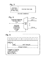
- FIG. 3 is a diagram depicting an exemplary voltage command format.
- FIG. 4 is a schematic block diagram depicting an exemplary voltage command distribution bus to support the voltage command format of FIG. 3 .
- FIG. 5 is a more detailed depiction of the voltage command format of FIG. 3 .
- FIG. 6 is a more detailed depiction of the schematic block diagram of FIG. 4 to support the voltage command format of FIG. 5 .
- FIG. 7 is a flowchart illustrating a process for lowering the voltage and frequency of SoC processor cores in response to sensing over-threshold temperatures.
- FIG. 8 is a flowchart illustrating a method for using a management module to monitor and dynamically control processor core operating voltages on an SOC.
- FIG. 2 is a schematic block diagram of a system-on-chip (SoC) 200 with a system for monitoring and dynamically controlling processor core operating voltages.
- the system 202 comprises a temperature sensor 204 having an output on line 206 to supply a temperature reading. Shown are a plurality of temperature sensors 204 - 0 through 204 - n , where n is an integer variable not limited to any particular value.
- the system 202 includes a plurality of processor cores 208 , each having an input on line 210 to receive an operating voltage. Shown are processor cores 208 - 0 through 208 - m , where m is an integer variable not limited to any particular value.
- the temperature sensors 204 are physically mounted in a location near the processor cores 208 . Alternatively but not shown, the sensors 204 are co-located with the processor.
- the system 202 also includes a plurality of voltage regulators 212 .
- Each voltage regulator 212 has an input on line 214 to receive a voltage command and an output on line 210 to supply an operating voltage to a processor core responsive to the voltage command on line 214 .
- An internal management module 216 has an input on line 206 to accept temperature readings. The management module 216 generates voltage commands supplied at an output on line 214 in response to comparing monitored temperatures to threshold values.
- the management module 216 may monitor an above-threshold temperature recorded by a first temperature sensor 204 - 0 and generate a first voltage command on line 214 - 0 . Then, the first voltage regulator 212 - 0 decreases a first operating voltage supplied to a first processor core 208 - 0 in response to the first voltage command on line 214 - 0 .
- each processor core 208 also has an input on line 218 to accept an operating frequency command. Then, the management module 216 may send a first frequency command to the first processor core on line 218 - 0 , directing the first processor core 208 - 0 to operate at a reduced processor frequency. If the above-mentioned operations are successful, the management module 216 is able to monitor a reduced temperature recorded by the first temperature sensor 204 - 0 in response to the first voltage command and first frequency command.
- the management module 216 is an independent processor core hardware block that is able to function without off-SoC commands or user direction.
- One function performed by the management module is the selection of the voltages and frequencies at which the various processor cores operate.
- the management module 216 selects the first processor core 208 - 0 to operate at a reduced voltage in response to monitoring the above-threshold temperature recorded by a first temperature sensor. This selection process is responsive to the management core analyzing criteria.
- processor core priority For example, processor core 208 - 0 may be assigned the lowest priority, so that it is the first to be cooled in the event of a thermal problem.
- the criterion may also include processor core workload. For example, the first processor core 208 - 0 may be selected because it is determined that it has a smaller workload than the other processor cores.
- Another criterion may be the priority of tasks being performed by processor cores. In this case, the management core would most likely be linked to an operating system (OS) module or software application able to prioritize the applications being supported by a processor core.
- OS operating system
- Another criterion is the thermal linkage between the first temperature sensor and the processor cores. For example, the first processor core may be selected because it is physically closest to the temperature sensor.
- PCB printed circuit board
- FIG. 3 is a diagram depicting an exemplary voltage command format.
- the management module may generate voltage commands each including a voltage field 300 and a voltage regulator identification (ID) field 302 .
- ID voltage regulator identification
- FIG. 4 is a schematic block diagram depicting an exemplary voltage command distribution bus to support the voltage command format of FIG. 3 .
- a multiplexer (MUX) 400 has a signal input on line 214 a to accept the voltage field, a control input on line 214 b to accept the voltage regulator ID field.
- a plurality of signal outputs 214 - 0 through 214 - m are selected in response to the voltage regulator ID field. Each signal output is connected to the input of a corresponding voltage regulator.
- the management module 216 prior to generating the first voltage command, generates a fan command on line 222 that is sent to a fan 220 external to the SoC 200 , directing the fan to initiate operation. If the management module 216 continues to monitor an above-threshold temperature recorded by the first temperature sensor 204 - 0 subsequent to initiating the fan operation, it then generates the first voltage command to lower the supply voltage to the first processor core 208 - 0 .
- the management module subsequent to sending the first frequency command, continues to monitor an above-threshold temperature recorded by the first temperature sensor 204 - 0 , it may generate a modified first voltage command on line 214 - 0 to further decrease the first voltage supplied by the first voltage regulator 212 - 0 .
- the management module 216 may further send a modified first frequency command on line 218 - 0 directing the first processor core 208 - 0 to further reduce the processor frequency.
- the management module 216 subsequent to sending the first frequency command, continues to monitor an above-threshold temperature recorded by the first temperature sensor 204 - 0 .
- the management module may generate a second voltage command sent for a second processor core ( 208 - 1 ), having a higher priority than the first processor core 208 - 0 .
- the second voltage regulator 212 - 1 adjusts the operating voltage supplied to the second processor core 208 - 1 in response to the second voltage command.
- the management module 216 may continue to monitor an above-threshold temperature recorded by the first temperature sensor 204 - 0 .
- the management module may generate an interrupt message, sent via an external interface on line 224 , indicating that the SoC is operating at an above-threshold temperature.
- core refers to an integrated circuit die of connected hardware sub-components that supply electrical signals in response to electrical signal stimuli. While these electrical signals may be indirectly affected by software operations performed external to die, there is no processor or software application internal to the die generating electrical signals. Any logic functions performed internal to the core are the result of a hardware based state machine type logic.
- management module also referred to as a thermal management core
- SYSTEM-ON-CHIP WITH THERMAL MANAGEMENT CORE invented by Waseem Kraipak et al., Ser. No. 12/687,817, filed Jan. 14, 2010, which is incorporated herein by reference.
- Other details of the management module, also referred to as a controller can be found in the parent application entitled, SYSTEM-ON-CHIP WITH FEEDBACK LOOP FOR PROCESSOR FREQUENCY CONTROL, invented by Waseem Kraipak et al., Ser. No. 12/639,064, filed Dec. 16, 2009, which is incorporated herein by reference.
- FIG. 5 is a more detailed depiction of the voltage command format of FIG. 3 .
- This 12-bit protocol can be used to control the voltage for individual processor cores.
- the lower 8 bits are the VID (voltage ID) bits that indicate the desired voltage level.
- Bit[9:8] indicate the COREID.
- the COREID selects the voltage regulator being addressed.
- Bit 10 is the enable bit.
- Bit 11 is a stop bit.
- FIG. 6 is a more detailed depiction of the schematic block diagram of FIG. 4 to support the voltage command format of FIG. 5 .
- Bit 10 of the voltage command is used to latch MUXs 600
- bit 11 is used to reset the serial in/parallel out (SIPO) device 602 .
- the voltage command is accompanied by a clock (S_CVB_CLK).
- the SoC may be a quad-core central processing unit (CPU) running different applications on the CPU.
- CPU central processing unit
- a single core is operational and the other cores are idle. If the application is currently being executed on CORE1, then CORE2, CORE3, and CORE4 are just in an idle mode.
- the management module monitoring the activities for each core might make the following decision.
- the management module may start increasing the frequency of CORE1 by sending a 12 Bit VID packet for CORE1. The frequency and voltage may be increased in steps.
- Each VID bit is transmitted serially on the positive edge of the S_CVB_CLK.
- the SIPO 602 coverts this bit stream into parallel bits.
- S_CVB [9:8] are the voltage regulator ID, which typically corresponds to a processor core with a dedicated voltage regulator. These bits enable a corresponding latch.
- Bit 10 is used as an enable to latch. When it is asserted, the new 8-bit VID value is at the output of the latch.
- Bit 11 is used as a reset or clear signal. When this bit is asserted at the next rising edge of the clock signal, the SIPO out is cleared. This means Bit 10 is deasserted and the 8 VID bits are latched.
- each latch 600 is connected to a voltage regulator 212 .
- Each voltage regulator adjusts a core voltage.
- CORE1 can be put to a new voltage level.
- the management module may begin to put CORE2 and CORE3 in low frequency and low voltage domain, ensuring that CORE1 can safely work at the highest frequency and voltage levels. Overall, the core power is reduced by around 75%.
- a user is running two applications being executed on CORE1 and CORE2.
- CORE1 is running an office type of application and
- CORE2 is running a graphics type of application.
- CORE3 and CORE4 are just in the idle mode and are not executing any applications.
- the management module decides to lower the operating voltage and frequency of CORE3. As in the first example, each VID bit is transmitted serially on the positive edge of the S_CVB_CLK. Similarly, the voltage and frequency of CORE4 may be lowered.
- the management module can then put CORE1 and CORE2 at optimal frequency and voltage domain levels, depending upon the work load. These operations can reduce the overall core power by around 50%.
- FIG. 7 is a flowchart illustrating a process for lowering the voltage and frequency of SoC processor cores in response to sensing over-threshold temperatures.
- the process begins at Step 700 . If an over-threshold temperature is detected in Step 702 , Step 704 turns on a fan. If an over-threshold temperature is not detected in Step 706 , the process returns to Step 702 . Otherwise, Step 708 selects one or more processor cores. Step 710 lowers the operating voltages and frequency of the selected processor core. If an over-threshold temperature is not detected in Step 712 , the process returns to Step 702 . Otherwise, the process may return to Step 710 to lower the voltage and frequency again.
- Step 714 may select another processor core(s) and Step 716 lowers the voltage and frequency of the selected core. If an over-threshold temperature is not detected in Step 718 , the process returns to Step 702 . Otherwise, the process may return to Step 716 to lower the voltage and frequency again. Alternatively, Step 710 may send an interrupt message to an off-SoC destination.
- FIG. 8 is a flowchart illustrating a method for using a management module to monitor and dynamically control processor core operating voltages on an SOC.
- the method is depicted as a sequence of numbered steps for clarity, the numbering does not necessarily dictate the order of the steps. It should be understood that some of these steps may be skipped, performed in parallel, or performed without the requirement of maintaining a strict order of sequence. Generally however, the method follows the numeric order of the depicted steps.
- the method starts at Step 800 .
- Step 802 provides an SoC with a plurality of processor cores, a plurality of voltage regulators, an internal management module, and a temperature sensor.
- the management module compares monitored temperatures to threshold values. In response to comparing monitored temperatures to the threshold values, the management module generates voltage commands in Step 806 .
- the management module sends the voltage commands to the voltage regulators.
- each voltage regulator adjusts the operating voltage supplied to a corresponding processor core in response to the voltage commands.
- comparing monitored temperatures to threshold values in Step 804 includes monitoring an above-threshold temperature recorded by a first temperature sensor.
- Generating the voltage commands in Step 806 includes generating a first voltage command to decrease a first voltage supplied by a first voltage regulator, and adjusting the operating voltage supplied to the corresponding processor core in response to the voltage commands in Step 810 includes supplying the decreased first voltage to a first processor core.
- Step 812 the management module may send a first frequency command to the first processor core, directing the first processor core to operate at a reduced processor frequency.
- the management module monitors a reduced temperature recorded by the first temperature sensor in response to the first voltage command and first frequency command. Note: Step 812 may be performed concurrently with Steps 806 through 810 .
- the management module selects the first processor core to operate at a reduced voltage in Step 805 c , in response to monitoring the above-threshold temperature recorded by a first temperature sensor.
- the management module selects the first processor core to operate at a reduced voltage in response to analyzing criteria such as processor core priority, processor core workload, the priority of tasks being performed by processor cores, the thermal linkage between the first temperature sensor and the processor cores, and combinations of the above-mentioned criteria.
- Step 816 may continue to monitor an above-threshold temperature recorded by the first temperature sensor. Then Step 806 generates a modified first voltage command to further decrease the first voltage supplied by the first voltage regulator, and Step 812 sends the modified first frequency command directing the first processor core to further reduce the processor frequency.
- generating the voltage command in Step 806 includes generating a voltage command including a voltage field and a voltage regulator identification (ID) field.
- Sending the voltage command in Step 808 then includes the following substeps.
- Step 808 a extracts the voltage regulator ID field, and Step 808 b multiplexes the voltage field to a voltage regulator associated with the extracted voltage regulator ID field.
- Step 805 a prior to generating the first voltage command in Step 806 , Step 805 a generates a fan command and Step 805 b sends the fan command to a fan external to the SoC, directing the fan to initiate operation or increase speed if applicable. Then, the first voltage command is generated in Step 806 in response to continued monitoring of an above-threshold temperature recorded by the first temperature sensor, subsequent to initiating the fan operation.
- Step 816 subsequent to sending the first frequency command in Step 806 , Step 816 continues to monitor an above-threshold temperature recorded by the first temperature sensor. Step 820 generates a second voltage command. Step 822 sends the second voltage command for a second processor core, having a higher priority than the first processor core. In Step 824 a second voltage regulator adjusts the operating voltage supplied to the second processor core in response to the second voltage command.
- Step 826 may continue to monitor an above-threshold temperature recorded by the first temperature sensor. Then, Step 828 generates an interrupt message, indicating that the SoC is operating at an above-threshold temperature, and Step 830 sends the interrupt message via an external interface.
- a system and method have been provided for using a management module to independently control processor cores in a SoC. Examples of particular message structures, processors, and hardware units have been presented to illustrate the invention. However, the invention is not limited to merely these examples. Other variations and embodiments of the invention will occur to those skilled in the art.
Landscapes
- Engineering & Computer Science (AREA)
- Theoretical Computer Science (AREA)
- Physics & Mathematics (AREA)
- General Engineering & Computer Science (AREA)
- General Physics & Mathematics (AREA)
- Human Computer Interaction (AREA)
- Power Sources (AREA)
Abstract
Description
Claims (20)
Priority Applications (2)
| Application Number | Priority Date | Filing Date | Title |
|---|---|---|---|
| US12/900,828 US8635470B1 (en) | 2009-12-16 | 2010-10-08 | System-on-chip with management module for controlling processor core internal voltages |
| US13/014,616 US8832483B1 (en) | 2009-12-16 | 2011-01-26 | System-on-chip with power-save mode processor |
Applications Claiming Priority (3)
| Application Number | Priority Date | Filing Date | Title |
|---|---|---|---|
| US12/639,064 US8868956B1 (en) | 2009-12-16 | 2009-12-16 | System-on-chip with feedback loop for processor frequency control |
| US12/687,817 US8786449B1 (en) | 2009-12-16 | 2010-01-14 | System-on-chip with thermal management core |
| US12/900,828 US8635470B1 (en) | 2009-12-16 | 2010-10-08 | System-on-chip with management module for controlling processor core internal voltages |
Related Parent Applications (1)
| Application Number | Title | Priority Date | Filing Date |
|---|---|---|---|
| US12/687,817 Continuation-In-Part US8786449B1 (en) | 2009-12-16 | 2010-01-14 | System-on-chip with thermal management core |
Related Child Applications (1)
| Application Number | Title | Priority Date | Filing Date |
|---|---|---|---|
| US13/014,616 Continuation-In-Part US8832483B1 (en) | 2009-12-16 | 2011-01-26 | System-on-chip with power-save mode processor |
Publications (1)
| Publication Number | Publication Date |
|---|---|
| US8635470B1 true US8635470B1 (en) | 2014-01-21 |
Family
ID=49919352
Family Applications (1)
| Application Number | Title | Priority Date | Filing Date |
|---|---|---|---|
| US12/900,828 Active 2031-08-09 US8635470B1 (en) | 2009-12-16 | 2010-10-08 | System-on-chip with management module for controlling processor core internal voltages |
Country Status (1)
| Country | Link |
|---|---|
| US (1) | US8635470B1 (en) |
Cited By (26)
| Publication number | Priority date | Publication date | Assignee | Title |
|---|---|---|---|---|
| US20130191690A1 (en) * | 2012-01-19 | 2013-07-25 | International Business Machines Corporation | In situ processor re-characterization |
| US20130219196A1 (en) * | 2008-10-31 | 2013-08-22 | Lev Finkelstein | Power management for multiple processor cores |
| US20130283083A1 (en) * | 2011-09-30 | 2013-10-24 | Reed D. Vilhauer | Maintaining operational stability on a system on a chip |
| US20130293269A1 (en) * | 2012-04-26 | 2013-11-07 | Huawei Technologies Co., Ltd. | Method and apparatus for controlling chip performance |
| US20140006833A1 (en) * | 2012-06-29 | 2014-01-02 | Ruoying Mary Ma | Maximum current throttling |
| US20140189225A1 (en) * | 2012-12-28 | 2014-07-03 | Shaun M. Conrad | Independent Control Of Processor Core Retention States |
| US20140223205A1 (en) * | 2013-02-04 | 2014-08-07 | Ramnarayanan Muthukaruppan | Multiple voltage identification (vid) power architecture, a digital synthesizable low dropout regulator, and apparatus for improving reliability of power gates |
| US20140359311A1 (en) * | 2013-05-31 | 2014-12-04 | Sanjeev S. Jahagirdar | Controlling Power Delivery To A Processor Via A Bypass |
| WO2016062069A1 (en) * | 2014-10-22 | 2016-04-28 | 中兴通讯股份有限公司 | Method and device for adjusting core voltage of chip |
| WO2016106070A1 (en) * | 2014-12-23 | 2016-06-30 | Intel Corporation | Adjustment of voltage regulator based on power state |
| US20160366047A1 (en) * | 2013-10-03 | 2016-12-15 | International Business Machines Corporation | Temperature sensitive routing of data in a computer system |
| WO2017052990A1 (en) * | 2015-09-26 | 2017-03-30 | Intel Corporation | Technologies for temperature measurement of a processor |
| US20170212572A1 (en) * | 2016-01-26 | 2017-07-27 | Intel Corporation | PROVIDING ACCESS FROM OUTSIDE A MULTICORE PROCESSOR SoC TO INDIVIDUALLY CONFIGURE VOLTAGES |
| WO2017151274A3 (en) * | 2016-03-01 | 2017-12-14 | Qualcomm Incorporated | Voltage adjustment for thermal mitigation |
| WO2017213964A1 (en) * | 2016-06-10 | 2017-12-14 | Microsoft Technology Licensing, Llc | Voltage based thermal control of processing device |
| US9891700B2 (en) * | 2015-10-02 | 2018-02-13 | Infineon Technologies Austria Ag | Power management for datacenter power architectures |
| US10209726B2 (en) | 2016-06-10 | 2019-02-19 | Microsoft Technology Licensing, Llc | Secure input voltage adjustment in processing devices |
| US10248186B2 (en) | 2016-06-10 | 2019-04-02 | Microsoft Technology Licensing, Llc | Processor device voltage characterization |
| US10331186B2 (en) * | 2014-07-25 | 2019-06-25 | Intel Corporation | Adaptive algorithm for thermal throttling of multi-core processors with non-homogeneous performance states |
| US10338670B2 (en) | 2016-06-10 | 2019-07-02 | Microsoft Technology Licensing, Llc | Input voltage reduction for processing devices |
| EP3506510A1 (en) * | 2017-12-27 | 2019-07-03 | INTEL Corporation | Systems and methods for integrating power and thermal management in an integrated circuit |
| US20200201420A1 (en) * | 2017-04-21 | 2020-06-25 | Intel Corporation | Dynamically power on/off processing clusters during execution |
| CN114185834A (en) * | 2020-09-15 | 2022-03-15 | 阿里巴巴集团控股有限公司 | System on chip and method for voltage and frequency regulation |
| US20220091644A1 (en) * | 2021-12-02 | 2022-03-24 | Intel Corporation | Thermally optimized power delivery |
| CN116100778A (en) * | 2023-04-12 | 2023-05-12 | 四川联塑科技实业有限公司 | A PE/PPR pipe rapid cooling forming device and its control system and method |
| US11960310B2 (en) | 2020-09-17 | 2024-04-16 | Samsung Electronics Co., Ltd. | Power supply method using a plurality of voltage sources and electronic device using the same |
Citations (5)
| Publication number | Priority date | Publication date | Assignee | Title |
|---|---|---|---|---|
| US20060161375A1 (en) * | 2004-12-30 | 2006-07-20 | Allen Duberstein | Optimizing processing speed based on measured temperatures |
| US20070070673A1 (en) * | 2005-09-28 | 2007-03-29 | Shekhar Borkar | Power delivery and power management of many-core processors |
| US20070198863A1 (en) * | 2006-02-17 | 2007-08-23 | Pradip Bose | Method and system for controlling power in a chip through a power-performance monitor and control unit |
| US20080244294A1 (en) * | 2007-03-29 | 2008-10-02 | Allarey Jose P | Dynamic power reduction |
| US20090322409A1 (en) * | 2008-06-26 | 2009-12-31 | Maxim Levit | Power reduction apparatus and method |
-
2010
- 2010-10-08 US US12/900,828 patent/US8635470B1/en active Active
Patent Citations (5)
| Publication number | Priority date | Publication date | Assignee | Title |
|---|---|---|---|---|
| US20060161375A1 (en) * | 2004-12-30 | 2006-07-20 | Allen Duberstein | Optimizing processing speed based on measured temperatures |
| US20070070673A1 (en) * | 2005-09-28 | 2007-03-29 | Shekhar Borkar | Power delivery and power management of many-core processors |
| US20070198863A1 (en) * | 2006-02-17 | 2007-08-23 | Pradip Bose | Method and system for controlling power in a chip through a power-performance monitor and control unit |
| US20080244294A1 (en) * | 2007-03-29 | 2008-10-02 | Allarey Jose P | Dynamic power reduction |
| US20090322409A1 (en) * | 2008-06-26 | 2009-12-31 | Maxim Levit | Power reduction apparatus and method |
Cited By (55)
| Publication number | Priority date | Publication date | Assignee | Title |
|---|---|---|---|---|
| US20130219196A1 (en) * | 2008-10-31 | 2013-08-22 | Lev Finkelstein | Power management for multiple processor cores |
| US20130283083A1 (en) * | 2011-09-30 | 2013-10-24 | Reed D. Vilhauer | Maintaining operational stability on a system on a chip |
| US9152518B2 (en) * | 2012-01-19 | 2015-10-06 | International Business Machines Corporation | In situ processor re-characterization |
| US20130191678A1 (en) * | 2012-01-19 | 2013-07-25 | International Business Machines Corporation | In situ processor re-characterization |
| US20130191690A1 (en) * | 2012-01-19 | 2013-07-25 | International Business Machines Corporation | In situ processor re-characterization |
| US9176837B2 (en) * | 2012-01-19 | 2015-11-03 | International Business Machines Corporation | In situ processor re-characterization |
| US20130293269A1 (en) * | 2012-04-26 | 2013-11-07 | Huawei Technologies Co., Ltd. | Method and apparatus for controlling chip performance |
| US9509293B2 (en) * | 2012-04-26 | 2016-11-29 | Huawei Technologies Co., Ltd. | Method and apparatus for controlling chip performance |
| US20140006833A1 (en) * | 2012-06-29 | 2014-01-02 | Ruoying Mary Ma | Maximum current throttling |
| US9274580B2 (en) * | 2012-06-29 | 2016-03-01 | Intel Corporation | Voltage regulator supplying power exclusively to a non-core region of a processor having a supply capability threshold |
| US20140189225A1 (en) * | 2012-12-28 | 2014-07-03 | Shaun M. Conrad | Independent Control Of Processor Core Retention States |
| US9081577B2 (en) * | 2012-12-28 | 2015-07-14 | Intel Corporation | Independent control of processor core retention states |
| US10185382B2 (en) | 2013-02-04 | 2019-01-22 | Intel Corporation | Multiple voltage identification (VID) power architecture, a digital synthesizable low dropout regulator, and apparatus for improving reliability of power gates |
| US20140223205A1 (en) * | 2013-02-04 | 2014-08-07 | Ramnarayanan Muthukaruppan | Multiple voltage identification (vid) power architecture, a digital synthesizable low dropout regulator, and apparatus for improving reliability of power gates |
| US10345881B2 (en) | 2013-02-04 | 2019-07-09 | Intel Corporation | Multiple voltage identification (VID) power architecture, a digital synthesizable low dropout regulator, and apparatus for improving reliability of power gates |
| US9766678B2 (en) * | 2013-02-04 | 2017-09-19 | Intel Corporation | Multiple voltage identification (VID) power architecture, a digital synthesizable low dropout regulator, and apparatus for improving reliability of power gates |
| US11157052B2 (en) * | 2013-05-31 | 2021-10-26 | Intel Corporation | Controlling power delivery to a processor via a bypass |
| US10429913B2 (en) | 2013-05-31 | 2019-10-01 | Intel Corporation | Controlling power delivery to a processor via a bypass |
| US10146283B2 (en) | 2013-05-31 | 2018-12-04 | Intel Corporation | Controlling power delivery to a processor via a bypass |
| US9823719B2 (en) * | 2013-05-31 | 2017-11-21 | Intel Corporation | Controlling power delivery to a processor via a bypass |
| US10409346B2 (en) | 2013-05-31 | 2019-09-10 | Intel Corporation | Controlling power delivery to a processor via a bypass |
| US11687135B2 (en) | 2013-05-31 | 2023-06-27 | Tahoe Research, Ltd. | Controlling power delivery to a processor via a bypass |
| US20140359311A1 (en) * | 2013-05-31 | 2014-12-04 | Sanjeev S. Jahagirdar | Controlling Power Delivery To A Processor Via A Bypass |
| US20160366047A1 (en) * | 2013-10-03 | 2016-12-15 | International Business Machines Corporation | Temperature sensitive routing of data in a computer system |
| US9838300B2 (en) * | 2013-10-03 | 2017-12-05 | International Business Machines Corporation | Temperature sensitive routing of data in a computer system |
| US10331186B2 (en) * | 2014-07-25 | 2019-06-25 | Intel Corporation | Adaptive algorithm for thermal throttling of multi-core processors with non-homogeneous performance states |
| WO2016062069A1 (en) * | 2014-10-22 | 2016-04-28 | 中兴通讯股份有限公司 | Method and device for adjusting core voltage of chip |
| WO2016106070A1 (en) * | 2014-12-23 | 2016-06-30 | Intel Corporation | Adjustment of voltage regulator based on power state |
| WO2017052990A1 (en) * | 2015-09-26 | 2017-03-30 | Intel Corporation | Technologies for temperature measurement of a processor |
| US10318396B2 (en) | 2015-09-26 | 2019-06-11 | Intel Corporation | Technologies for temperature measurement of a processor |
| US9891700B2 (en) * | 2015-10-02 | 2018-02-13 | Infineon Technologies Austria Ag | Power management for datacenter power architectures |
| US11892969B2 (en) | 2016-01-26 | 2024-02-06 | Intel Corporation | Providing access from outside a multicore processor SoC to individually configure voltages |
| US10013392B2 (en) * | 2016-01-26 | 2018-07-03 | Intel Corporation | Providing access from outside a multicore processor SoC to individually configure voltages |
| US11216409B2 (en) | 2016-01-26 | 2022-01-04 | Intel Corporation | Providing access from outside a multicore processor SoC to individually configure voltages |
| US10783110B2 (en) | 2016-01-26 | 2020-09-22 | Intel Corporation | Providing access from outside a multicore processor SoC to individually configure voltages |
| US20170212572A1 (en) * | 2016-01-26 | 2017-07-27 | Intel Corporation | PROVIDING ACCESS FROM OUTSIDE A MULTICORE PROCESSOR SoC TO INDIVIDUALLY CONFIGURE VOLTAGES |
| EP3460629A1 (en) * | 2016-03-01 | 2019-03-27 | QUALCOMM Incorporated | Voltage adjustment for thermal mitigation |
| WO2017151274A3 (en) * | 2016-03-01 | 2017-12-14 | Qualcomm Incorporated | Voltage adjustment for thermal mitigation |
| US10103714B2 (en) | 2016-03-01 | 2018-10-16 | Qualcomm Incorporated | Adjust voltage for thermal mitigation |
| US10338670B2 (en) | 2016-06-10 | 2019-07-02 | Microsoft Technology Licensing, Llc | Input voltage reduction for processing devices |
| WO2017213964A1 (en) * | 2016-06-10 | 2017-12-14 | Microsoft Technology Licensing, Llc | Voltage based thermal control of processing device |
| US10310572B2 (en) | 2016-06-10 | 2019-06-04 | Microsoft Technology Licensing, Llc | Voltage based thermal control of processing device |
| US10248186B2 (en) | 2016-06-10 | 2019-04-02 | Microsoft Technology Licensing, Llc | Processor device voltage characterization |
| CN109313473B (en) * | 2016-06-10 | 2022-08-02 | 微软技术许可有限责任公司 | Voltage-based thermal control of processing devices |
| US10209726B2 (en) | 2016-06-10 | 2019-02-19 | Microsoft Technology Licensing, Llc | Secure input voltage adjustment in processing devices |
| CN109313473A (en) * | 2016-06-10 | 2019-02-05 | 微软技术许可有限责任公司 | The thermal control based on voltage of processing equipment |
| US20200201420A1 (en) * | 2017-04-21 | 2020-06-25 | Intel Corporation | Dynamically power on/off processing clusters during execution |
| US11989076B2 (en) * | 2017-04-21 | 2024-05-21 | Intel Corporation | Dynamically power on/off processing clusters during execution |
| US11520388B2 (en) | 2017-12-27 | 2022-12-06 | Intel Corporation | Systems and methods for integrating power and thermal management in an integrated circuit |
| EP3506510A1 (en) * | 2017-12-27 | 2019-07-03 | INTEL Corporation | Systems and methods for integrating power and thermal management in an integrated circuit |
| CN114185834A (en) * | 2020-09-15 | 2022-03-15 | 阿里巴巴集团控股有限公司 | System on chip and method for voltage and frequency regulation |
| US11960310B2 (en) | 2020-09-17 | 2024-04-16 | Samsung Electronics Co., Ltd. | Power supply method using a plurality of voltage sources and electronic device using the same |
| US20220091644A1 (en) * | 2021-12-02 | 2022-03-24 | Intel Corporation | Thermally optimized power delivery |
| US12436584B2 (en) * | 2021-12-02 | 2025-10-07 | Intel Corporation | Thermally optimized power delivery |
| CN116100778A (en) * | 2023-04-12 | 2023-05-12 | 四川联塑科技实业有限公司 | A PE/PPR pipe rapid cooling forming device and its control system and method |
Similar Documents
| Publication | Publication Date | Title |
|---|---|---|
| US8635470B1 (en) | System-on-chip with management module for controlling processor core internal voltages | |
| US8880922B2 (en) | Computer and power management system for computer | |
| JP5189921B2 (en) | Computer heat dissipation system | |
| US8504861B2 (en) | Data processing system having power capping function in response to output state of power supply module | |
| JP5235590B2 (en) | Electronic system power management method, system, and program (electronic system power management) | |
| KR101827666B1 (en) | Energy efficiency aware thermal management in a multi-processor system on a chip | |
| US7783903B2 (en) | Limiting power consumption by controlling airflow | |
| US9436256B2 (en) | Dynamic CPU voltage regulator phase shedding | |
| EP2766788B1 (en) | System and method for determining thermal management policy from leakage current measurement | |
| JP4448101B2 (en) | Electronic device cooling system, computer and cooling method | |
| US20130090888A1 (en) | System and method for proximity based thermal management of mobile device | |
| US7310738B2 (en) | Multifunctional control of cooling systems for computers | |
| EP2929409A1 (en) | System and method for estimating ambient temperaure from a portable computing device | |
| KR20150012235A (en) | Voltage regulator control system | |
| KR20110041286A (en) | Computer system and its control method | |
| JP2006146605A (en) | Information processor, control method, and program | |
| JP2007042091A (en) | Power monitoring of processor module | |
| CN111061356B (en) | Power management system and power management method | |
| CN101994717A (en) | Atca fan control method and atca machine frame manager | |
| US20070124609A1 (en) | System and method for controlling cpu overclocking | |
| US7152013B2 (en) | Heat dissipating method | |
| CN106292972A (en) | Power supply loop for computing server | |
| US20250348397A1 (en) | Power management method and power management device | |
| EP2821880B1 (en) | Power control system and method thereof | |
| WO2016127611A1 (en) | Speed regulation method and device for controllable fan |
Legal Events
| Date | Code | Title | Description |
|---|---|---|---|
| AS | Assignment |
Owner name: APPLIED MICRO CIRCUITS CORPORATION, CALIFORNIA Free format text: ASSIGNMENT OF ASSIGNORS INTEREST;ASSIGNORS:KRAIPAK, WASEEM;BENDAK, GEORGE;SIGNING DATES FROM 20101007 TO 20101008;REEL/FRAME:025113/0435 |
|
| STCF | Information on status: patent grant |
Free format text: PATENTED CASE |
|
| FEPP | Fee payment procedure |
Free format text: PAYOR NUMBER ASSIGNED (ORIGINAL EVENT CODE: ASPN); ENTITY STATUS OF PATENT OWNER: LARGE ENTITY |
|
| AS | Assignment |
Owner name: MACOM CONNECTIVITY SOLUTIONS, LLC, MASSACHUSETTS Free format text: MERGER AND CHANGE OF NAME;ASSIGNORS:APPLIED MICRO CIRCUITS CORPORATION;MACOM CONNECTIVITY SOLUTIONS, LLC;MACOM CONNECTIVITY SOLUTIONS, LLC;SIGNING DATES FROM 20170126 TO 20170127;REEL/FRAME:042176/0185 |
|
| AS | Assignment |
Owner name: GOLDMAN SACHS BANK USA, AS COLLATERAL AGENT, NEW Y Free format text: SECURITY INTEREST;ASSIGNOR:MACOM CONNECTIVITY SOLUTIONS, LLC (SUCCESSOR TO APPLIED MICRO CIRCUITS CORPORATION);REEL/FRAME:042444/0891 Effective date: 20170504 Owner name: GOLDMAN SACHS BANK USA, AS COLLATERAL AGENT, NEW YORK Free format text: SECURITY INTEREST;ASSIGNOR:MACOM CONNECTIVITY SOLUTIONS, LLC (SUCCESSOR TO APPLIED MICRO CIRCUITS CORPORATION);REEL/FRAME:042444/0891 Effective date: 20170504 |
|
| FPAY | Fee payment |
Year of fee payment: 4 |
|
| MAFP | Maintenance fee payment |
Free format text: PAYMENT OF MAINTENANCE FEE, 8TH YEAR, LARGE ENTITY (ORIGINAL EVENT CODE: M1552); ENTITY STATUS OF PATENT OWNER: LARGE ENTITY Year of fee payment: 8 |
|
| MAFP | Maintenance fee payment |
Free format text: PAYMENT OF MAINTENANCE FEE, 12TH YEAR, LARGE ENTITY (ORIGINAL EVENT CODE: M1553); ENTITY STATUS OF PATENT OWNER: LARGE ENTITY Year of fee payment: 12 |