US861069A - Transmission mechanism. - Google Patents
Transmission mechanism. Download PDFInfo
- Publication number
- US861069A US861069A US36103507A US1907361035A US861069A US 861069 A US861069 A US 861069A US 36103507 A US36103507 A US 36103507A US 1907361035 A US1907361035 A US 1907361035A US 861069 A US861069 A US 861069A
- Authority
- US
- United States
- Prior art keywords
- shaft
- pulley
- cone
- swinging
- swinging shaft
- Prior art date
- Legal status (The legal status is an assumption and is not a legal conclusion. Google has not performed a legal analysis and makes no representation as to the accuracy of the status listed.)
- Expired - Lifetime
Links
Images

Classifications
-
- F—MECHANICAL ENGINEERING; LIGHTING; HEATING; WEAPONS; BLASTING
- F16—ENGINEERING ELEMENTS AND UNITS; GENERAL MEASURES FOR PRODUCING AND MAINTAINING EFFECTIVE FUNCTIONING OF MACHINES OR INSTALLATIONS; THERMAL INSULATION IN GENERAL
- F16H—GEARING
- F16H15/00—Gearings for conveying rotary motion with variable gear ratio, or for reversing rotary motion, by friction between rotary members
- F16H15/02—Gearings for conveying rotary motion with variable gear ratio, or for reversing rotary motion, by friction between rotary members without members having orbital motion
- F16H15/04—Gearings providing a continuous range of gear ratios
- F16H15/06—Gearings providing a continuous range of gear ratios in which a member A of uniform effective diameter mounted on a shaft may co-operate with different parts of a member B
- F16H15/16—Gearings providing a continuous range of gear ratios in which a member A of uniform effective diameter mounted on a shaft may co-operate with different parts of a member B in which the member B has a conical friction surface
- F16H15/18—Gearings providing a continuous range of gear ratios in which a member A of uniform effective diameter mounted on a shaft may co-operate with different parts of a member B in which the member B has a conical friction surface externally
- F16H15/20—Gearings providing a continuous range of gear ratios in which a member A of uniform effective diameter mounted on a shaft may co-operate with different parts of a member B in which the member B has a conical friction surface externally co-operating with the outer rim of the member A, which is perpendicular or nearly perpendicular to the friction surface of the member B
Definitions
- This invention relates to transmission mechanism, and is especiallyl useful 4in driving machinery at diffe ⁇ rent speeds. l
- the invention is especially applicable in the driving mechanism of vehicles, motor boats, and undery similar conditions where the machinery must have, a wide range of speeds.
- y I l The object of the invention is to produce a transmis-v sion mechanism of simple' construction, and which can be quickly controlled' so as to change the speed as desired.
- the invention consists inthe construction and combination 0f parts to be more fully described hereinafter and particularly set ⁇ forth in the claims.
- Figure 1 yis aybottom plan of the mechanism .
- con-V beam 5 is ⁇ disposed at the opposite end.
- the beam 5 is substantially ⁇ straight except at'one 'end Where it is formed into a curve'or arc 6, -for a purpose which will appear more'fully hereinafter; v
- pulley '1.5 is slidably connected with the shaft 13 through rthe medium of a key in the pulley engaging a key-seat lsjwhich Venables the pulley to rotate the shaft when thc'pulley is rotated from the icone.
- l lt should beunderstoodthat the curve G of the beam 5 constitutes a guide for" theI free end of the shaft 13, and this part is curved about the universal joint 12 as a center.
- the shaft ll is provided with a reversing'pulley 37 and a corresponding reversingpulley 38 is provided on the extremity of the sli-ait S, which is extended beyond the beam 4 so as to bringthe -pulleySS opposite the pulley S7. as illustrated in Figi.
- Between these pulleys 'a sli-alt 39 is supported on the beams 3 and 4, and on this shaft there is slid-ably mounted la pulley40 which is adapted to slide linto position between the pulleys 37 and 3S. constituting an idler to connect them and give the pulleyl 37 a reverse movement.
- the pulleys 37 and 3S are slightly conical, the small ends 'thereof being disposed toward the direction from which the pulley v40 advances when being introduced between them.
- a shifting collar 4l which is engaged bythe end of 'shifting lever 42, said shifting lever beingl pivotally mounted on a suitable bracket 43 and having a slot 44 formed at its free end to which is connected a shifting 4the universal joint l2 is located at some distance b eyopdthe endof the cone and adjacent to the universi joint.
- stop collar 47 is provided. If the pulley l5 is moved up to this collar 47, its face will be beyond the end ol' the cone-so that it is thrown out of Contact therewith, will be readily understood.
- a driving shaft in combination, a driving shaft, a cone carried thereby, u driven shaft.
- a swinging shaft having a universal connection with said drivenshaft, a pulley slidably mounted on said swinging shaft. adapted to engage said cone and adording means for rotating said swinging shaft, means for advancing-said pulley on saitkswinging shaft, and means for holding said pulley in contact with said cone.
- a driving shaft in combination. a driving shaft, a cone mounted thereon, a driven shaft, a swinging shaft having a universal connection with said driven shaft, a pulley sldably mounted on said swinging shaft and adapted to rotate the same.
- a frame a-dr-iving shaft rptatably mounted therein, a cone carried by said driving shaft, a driven shaft, a swinging shaft having ',a universal connection with said driven shaft, a pulley mounted to slide on said swinging shaft, adapted to engage said cone and affording means for rotating said swinging shaft,l an inclined guide bar, a slide mounted on said guide bar, connected with said pulley and affording means for advancing said pulley on said swinging shaft,
- a frame a driving shaft rotatably mounted therein, a cone carried by said driving shaft, a driven shaft, a swinging shaft having a universal connection with said driven shaft, a pulley mounted to slide on said swinging shaft, adapted to engage said cone and affording means for rotating said swinging shaft, an inclined guide bar, a slide mounted on said guide bar, connected with said pulley and affording means for advancing said pulley on said swinging shaft, means for advancing said slide on said guide bar, and means, for,-pressing said swinging shaft toward said cone to maintain said pulley in contact with the face o said coue.
- ln transmission mechanism in combination, a frame, a driving shaftl rotatably mounted therein, a cone carried hy said driving shaft, a driven shaft rotatably mounted in said frame.
- a swinging shaft having a universal connection with said driven shaft, a pulley slidably mounted -on said swinging ⁇ shaft. adapted to rotate said swinging shaft and engaging the face of said cone.
- a spring pulling said swinging shaft toward said cone and holding said pulley against said cone.
- an inclined guide bar a slide moving thereupon and havingl a yoke. said pulley having a collar engaging said yoke whereby said slide may advance said pulley onI said swinging shaft, a chain extending longitudinally of said guide bar and attached to said slide for advancing the same, and means for advancing said chain.
- a frame a driving shaft rotatably mounted in said frame. a one mounted on said shaft. a driven shaft: mounted in said frame. a swinging shaft having a .universal (connection with said driven shaft. means i'or guiding-the free end of said swinging shaft on said frame. a pulleyy sliding on said swinging shaft. adapted to rotate the same and engaging the face of said cone, means for pressing ⁇ said swinging shaft toward said cone to maintain said pulley,- in contact with said cone. and means for advancingvsaid pulley on said swinging shaft.
- a frame a driving shaft rotatably mounted therein, a cone carried by said shaft, a ydriven shaft, a swinging shaft having a universal connection ⁇ with said driven shaft, a pulley sliding; on said swinging shaft, affording means for rotating lsaid swinging shaft and normally engaging the face of said cone, means for advancing said pulley on said swinging shaft, a spring pulling said swinging shaft toward said cone so as to maintain said pulley in contact with the face of said cone, and means for forcing said swinging Y shaft away from said cone to disengage said pulley from said cone.
Landscapes
- Engineering & Computer Science (AREA)
- General Engineering & Computer Science (AREA)
- Mechanical Engineering (AREA)
- Sewing Machines And Sewing (AREA)
Description
PATENTED JULY 23, 19o?.
G.,H. Woon. y TRANSMISSION MEGHANISM.
APPLICATION I'IED MAB.. 7, 1907.
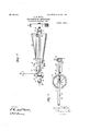
2 SHEETS-SHEET 2.
SYM/VV TTHA/EYS WOOD, OF GLEN COVE,ANEW YORK;
' 'raAnsMIssIoN MEGHANISM.
To all whoqu it may concern; i y' ABe it-known that 1I, GEORG-E-HnNnYMWoom-a. citizenof the'United States, and a residente-f GlenCove,
in the county of Nassau'and State ofN-ew York, have invented a new and Improved Transmission Mechan-l ism, of which the following is a full, clear7 and exact description. l f
This invention relates to transmission mechanism, and is especiallyl useful 4in driving machinery at diffe`rent speeds. l
The invention is especially applicable in the driving mechanism of vehicles, motor boats, and undery similar conditions where the machinery must have, a wide range of speeds. y I l The object of the invention is to produce a transmis-v sion mechanism of simple' construction, and which can be quickly controlled' so as to change the speed as desired. The invention consists inthe construction and combination 0f parts to be more fully described hereinafter and particularly set `forth in the claims.
Reference isfto` be had to the accompanying drawings forming a part4 of this specification, which simi'- lar characters of reference indicate corresponding parts in all the iigures.
Figure 1 yis aybottom plan of the mechanism .con-V beam 5 is` disposed at the opposite end.. The beam 5 is substantially` straight except at'one 'end Where it is formed into a curve'or arc 6, -for a purpose which will appear more'fully hereinafter; v
, Rotatablymounted in suitablebearings 7 on the beamsfl arret-5,.` la provider a'main shaft or driving shaft.
8; which is adapted to be continuously driven byr the engine or motor. 'At afsuitable :point this shaft-is pro- 'vided withfa flywheel'), and between the beams 4 and 5 it is provided' with an elongated conicalpulley 10.
-, Rotatably mounted in bearings o'nthe beams' 3 and 4, 1 provide a driven shaitll;y the ybody `of lthis shaft extends toward the left from the beam 3, and the other `nd'of this shaft extends a shortl distance `tothe right lof the beam A:A where it. is'connectiedbya .universal joint 12'with a swingingvshaftlfl ,The beamr: atfthze -curve 6 isv formed of two',curved bars 14, as indicated in Fig. 2, and these bars-hea short distance apar-t' so .i
as to form a guide for the end ofthe. shaft 13 which lies between the bars. On this swinging shaft 13'there is slidably mounted a driven pulley 15, the face whereof is adapted to rest against the, face of the cone .10, as
y l Specification of Letters Patent. j Application filed March 7.1907, Serial No. 361.035.
Patented Jury 23,1907.
indicated.y VThis pulley is provided with a shiftingv c01- lar.y 16 formed wilh a circumferential groove 17. The
pulley '1.5 is slidably connected with the shaft 13 through rthe medium of a key in the pulley engaging a key-seat lsjwhich Venables the pulley to rotate the shaft when thc'pulley is rotated from the icone.l lt should beunderstoodthat the curve G of the beam 5 constitutes a guide for" theI free end of the shaft 13, and this part is curved about the universal joint 12 as a center.
vRigidly mounted in the frame on theY side df the pulleyv 15 which' is remote from the cone 10, I provide an inclinedy guide bar 19 which is disposed substantially parallel with the adjacent face ofthe cone, as indicated. On :this guide bar lgth'ere i'sslidably" mountedl a slide or block 20, which block is formed with an arm 21 which projects toward the shaft 13 and is formed into a yoke 22 at its extremity, and this'yoke engages the groove 17 'of the collar 16, as shown in Fig. 1.
On the outer side of the guide vbar 19 an endless chain 23.s mounted uponv pulleys 24 and 25.` The pulley 25 is carried upon a shaft 26 provided with worm wheel 27, and this worm wheel is 'driven by a worm 28 carried upon a vertical Vspindle 29 which passes downwardly through the frame being suitably mounted in a bracket 30. At its upper end the spindle 29 is provided with a hand wheel 31 which enables the shaft 26 to be rotated laterally projecting ear 32 as shownI in Fig. 2. From this arrangement it shouldbe understood that 'if the hand wheel 31 rotated so asto advancethe slide 20 toward fthe right, as viewedI in Fig. 1, thepnlleyl will be advanced toward the large end of the cone,l and at-the same4 time the swinging shaft 13 will swing inwardly toward collarrSfl on the shaft 13 near thebeam 5; the inner end ofthe yspring being attachec'llto afsuitahle hracktf attached near the shaft S on the' frame. ""1`h`c small diameter of the cone v10 is less than that of the pulley] 5, while the large diameter'is greater", from which it follows that the shaft 11 ymaybe driv'en at a slower speed or a higherzspced than .that of the shaft 8. ln the position' shown in Fig. 1, the shaft 1.1 will bedriven ata slower A.
speed'. 1f the pulley 15 -isfadvanced toward the other i end ofthe conefthe speed. of the shaft'll will, of course,
gradually increase until it reaches a I* maximum/when the'pull'ey 15 isy at the largest diameter ofthe conc;
..."flnorderto enable'the transmission mechanism toghe suddenlyfthrown outgin case of an accident, I provide a i chain 36 which is .attached to the free end ofy the shaft '13; if this ychain be pulled, away from the shaft S/tl/ie i shaftfll will be swung outwardly so as to disengago the pulley l5 from the cone. I providemeans whereby the shafts maydrive the driven shaft 11 in a reverse cfr direction at'a reduced speed. Forthis purpose the shaft ll is provided with a reversing'pulley 37 and a corresponding reversingpulley 38 is provided on the extremity of the sli-ait S, which is extended beyond the beam 4 so as to bringthe -pulleySS opposite the pulley S7. as illustrated in Figi. Between these pulleys 'a sli-alt 39 is supported on the beams 3 and 4, and on this shaft there is slid-ably mounted la pulley40 which is adapted to slide linto position between the pulleys 37 and 3S. constituting an idler to connect them and give the pulleyl 37 a reverse movement. The pulleys 37 and 3S are slightly conical, the small ends 'thereof being disposed toward the direction from which the pulley v40 advances when being introduced between them. In order to shift the idler 'pulley 40, the same is provided with a shifting collar 4l which is engaged bythe end of 'shifting lever 42, said shifting lever beingl pivotally mounted on a suitable bracket 43 and having a slot 44 formed at its free end to which is connected a shifting 4the universal joint l2 is located at some distance b eyopdthe endof the cone and adjacent to the universi joint. a
stop collar 47 is provided. If the pulley l5 is moved up to this collar 47, its face will be beyond the end ol' the cone-so that it is thrown out of Contact therewith, will be readily understood.
Having thus described my invention, I-claim as new and desire to secure by Letters Patent:
1. In transmission mechanism, in combination, a driving shaft, a cone carried thereby, u driven shaft. a swinging shaft having a universal connection with said drivenshaft, a pulley slidably mounted on said swinging shaft. adapted to engage said cone and adording means for rotating said swinging shaft, means for advancing-said pulley on saitkswinging shaft, and means for holding said pulley in contact with said cone.
2. In mechanism of the class described, in combination. a driving shaft, a cone mounted thereon, a driven shaft, a swinging shaft having a universal connection with said driven shaft, a pulley sldably mounted on said swinging shaft and adapted to rotate the same. a spring Drilling l.said swinging shaft toward said cone and holding the face of said pulley against 'said cone,and means for advancing said pulley along said swinging shaft.
3. In transmission mechanism, in combination, a frame a-dr-iving shaft rptatably mounted therein, a cone carried by said driving shaft, a driven shaft, a swinging shaft having ',a universal connection with said driven shaft, a pulley mounted to slide on said swinging shaft, adapted to engage said cone and affording means for rotating said swinging shaft,l an inclined guide bar, a slide mounted on said guide bar, connected with said pulley and affording means for advancing said pulley on said swinging shaft,
and means for advancing said slide on said guide bar.
4. In transmission mechanism, in combination, a frame, a driving shaft rotatably mounted therein, a cone carried by said driving shaft, a driven shaft, a swinging shaft having a universal connection with said driven shaft, a pulley mounted to slide on said swinging shaft, adapted to engage said cone and affording means for rotating said swinging shaft, an inclined guide bar, a slide mounted on said guide bar, connected with said pulley and affording means for advancing said pulley on said swinging shaft, means for advancing said slide on said guide bar, and means, for,-pressing said swinging shaft toward said cone to maintain said pulley in contact with the face o said coue.
ln transmission mechanism, in combination, a frame, a driving shaftl rotatably mounted therein, a cone carried hy said driving shaft, a driven shaft rotatably mounted in said frame. a swinging shaft having a universal connection with said driven shaft, a pulley slidably mounted -on said swinging` shaft. adapted to rotate said swinging shaft and engaging the face of said cone. a spring pulling said swinging shaft toward said cone and holding said pulley against said cone. an inclined guide bar, a slide moving thereupon and havingl a yoke. said pulley having a collar engaging said yoke whereby said slide may advance said pulley onI said swinging shaft, a chain extending longitudinally of said guide bar and attached to said slide for advancing the same, and means for advancing said chain.
6. ln transmission mechanism. in combination. a frame. a driving shaft rotatably mounted in said frame. a one mounted on said shaft. a driven shaft: mounted in said frame. a swinging shaft having a .universal (connection with said driven shaft. means i'or guiding-the free end of said swinging shaft on said frame. a pulleyy sliding on said swinging shaft. adapted to rotate the same and engaging the face of said cone, means for pressing `said swinging shaft toward said cone to maintain said pulley,- in contact with said cone. and means for advancingvsaid pulley on said swinging shaft.
7. ln mechanism of the class described. in, combination. va frame. a driving shai't rotatably mounted therein and a conical pulley mounted thereupon, a driven shaft a conical pulley mounted thereupon opposite said lirst`pulley. said pulleys being arranged with the small ends thereof disposed opposite; means for normally, driving said driven shaft from said driving shaft in a forward direction. and a sliding pulley adapted to move into posi- 'ion between said iirsi.A ulleys and affording means for reversing the movement of said driven shaft.
' S. ln transmission mechanism. in combination. a frame. a driving shaft rotatably mounted therein, a cone carried by said shaft, a ydriven shaft, a swinging shaft having a universal connection` with said driven shaft, a pulley sliding; on said swinging shaft, affording means for rotating lsaid swinging shaft and normally engaging the face of said cone, means for advancing said pulley on said swinging shaft, a spring pulling said swinging shaft toward said cone so as to maintain said pulley in contact with the face of said cone, and means for forcing said swinging Y shaft away from said cone to disengage said pulley from said cone.
9. In' mechanism of .the class described, in combination, a frame, a driving shaft rotatably mounted therein, a cone carried' by said driving shaft, a driven shaft, a
'swinging shaft. having a universal connection with said driven shaft, a pulley sliding on said swinging lshaft, affording means for rotating the same and normally engaging the face of said cone, an inclined guide bar, a slide mounted on said guide barand having a yoke, said pulley having a collar engaged by said yoke whereby said slide may advance said pulley on said swinging shaft, means for advancing said slide, means for normally pressing said swinging shaft toward said cone Vto' maintain said pulley in contact with the face of said cone, and means for forcing said swinging shaft away from saidl cone to disengage said pulley therefrom.
ln testimony whereof l have signed my name yto this specification in the .presence of two subscribing witnesses.
` GEORGE HENRYWOOD.
Witnesses z f.
MICHEAL J. DoNoHUE, EDWARD F. Woon.
Priority Applications (1)
| Application Number | Priority Date | Filing Date | Title |
|---|---|---|---|
| US36103507A US861069A (en) | 1907-03-07 | 1907-03-07 | Transmission mechanism. |
Applications Claiming Priority (1)
| Application Number | Priority Date | Filing Date | Title |
|---|---|---|---|
| US36103507A US861069A (en) | 1907-03-07 | 1907-03-07 | Transmission mechanism. |
Publications (1)
| Publication Number | Publication Date |
|---|---|
| US861069A true US861069A (en) | 1907-07-23 |
Family
ID=2929522
Family Applications (1)
| Application Number | Title | Priority Date | Filing Date |
|---|---|---|---|
| US36103507A Expired - Lifetime US861069A (en) | 1907-03-07 | 1907-03-07 | Transmission mechanism. |
Country Status (1)
| Country | Link |
|---|---|
| US (1) | US861069A (en) |
Cited By (9)
| Publication number | Priority date | Publication date | Assignee | Title |
|---|---|---|---|---|
| US2776591A (en) * | 1957-01-08 | mcbride | ||
| US5425685A (en) * | 1994-01-06 | 1995-06-20 | Park; Bret J. | Continuous variable-ratio transmission |
| US5653143A (en) * | 1995-06-06 | 1997-08-05 | Langevin; David W. | Automatic mechanical variable ratio transmission |
| US6055880A (en) * | 1996-01-12 | 2000-05-02 | Designco Inc. | Transfer ring and gear arrangement for non-slip continuously variable transmission |
| US6349607B1 (en) | 1997-09-23 | 2002-02-26 | Designco Inc. | Transfer ring for continuously variable transmission |
| US6524214B1 (en) * | 2000-12-27 | 2003-02-25 | James A. Cillessen | Variable ratio transmission |
| US20070272048A1 (en) * | 2006-05-25 | 2007-11-29 | Arthur Vanmoor | Variable Speed Gear Transmission |
| WO2012038991A1 (en) * | 2010-09-21 | 2012-03-29 | Italycar S.R.L. | Speed variator |
| WO2021098681A1 (en) * | 2019-11-20 | 2021-05-27 | 叶慎世 | Speed regulation apparatus and speed changer |
-
1907
- 1907-03-07 US US36103507A patent/US861069A/en not_active Expired - Lifetime
Cited By (11)
| Publication number | Priority date | Publication date | Assignee | Title |
|---|---|---|---|---|
| US2776591A (en) * | 1957-01-08 | mcbride | ||
| US5425685A (en) * | 1994-01-06 | 1995-06-20 | Park; Bret J. | Continuous variable-ratio transmission |
| US5653143A (en) * | 1995-06-06 | 1997-08-05 | Langevin; David W. | Automatic mechanical variable ratio transmission |
| US6055880A (en) * | 1996-01-12 | 2000-05-02 | Designco Inc. | Transfer ring and gear arrangement for non-slip continuously variable transmission |
| US6349607B1 (en) | 1997-09-23 | 2002-02-26 | Designco Inc. | Transfer ring for continuously variable transmission |
| US6524214B1 (en) * | 2000-12-27 | 2003-02-25 | James A. Cillessen | Variable ratio transmission |
| US6997848B1 (en) * | 2000-12-27 | 2006-02-14 | James A. Cillessen | Variable ratio transmission with low gear |
| US20070272048A1 (en) * | 2006-05-25 | 2007-11-29 | Arthur Vanmoor | Variable Speed Gear Transmission |
| WO2012038991A1 (en) * | 2010-09-21 | 2012-03-29 | Italycar S.R.L. | Speed variator |
| US9243693B2 (en) | 2010-09-21 | 2016-01-26 | Italycar S.R.L. | Speed variator |
| WO2021098681A1 (en) * | 2019-11-20 | 2021-05-27 | 叶慎世 | Speed regulation apparatus and speed changer |
Similar Documents
| Publication | Publication Date | Title |
|---|---|---|
| US861069A (en) | Transmission mechanism. | |
| US1236749A (en) | Transmission-gearing. | |
| US1480021A (en) | Belt-pulley clutch control for tractors | |
| US1197535A (en) | Transmission-gearing. | |
| US912131A (en) | Friction-gearing. | |
| US1182379A (en) | Transmission mechanism. | |
| US592552A (en) | Drive-chain | |
| US1091338A (en) | Transmission and reversing gearing for engines. | |
| US839512A (en) | Variable-speed gear. | |
| US1043932A (en) | Clutch. | |
| US886911A (en) | Variable-speed gear. | |
| US556385A (en) | trayis | |
| US850698A (en) | Belt-tightener for sawmill feed mechanisms. | |
| US992211A (en) | Traction-engine. | |
| US1177880A (en) | Transmission-gear. | |
| US1230798A (en) | Transmission-gearing. | |
| US697720A (en) | Automobile. | |
| US1379728A (en) | Clutch | |
| US1393600A (en) | Auto-treadmill | |
| US733205A (en) | Reversing-gearing. | |
| US1179932A (en) | Steering mechanism for road-engines. | |
| US1248387A (en) | Transmission mechanism. | |
| US947386A (en) | Transmission mechanism. | |
| US1031723A (en) | Variable-speed mechanism for motor-vehicles. | |
| US942416A (en) | Speed-varying mechanism. |