US8588605B2 - Dual polarizing hood - Google Patents
Dual polarizing hood Download PDFInfo
- Publication number
- US8588605B2 US8588605B2 US13/246,590 US201113246590A US8588605B2 US 8588605 B2 US8588605 B2 US 8588605B2 US 201113246590 A US201113246590 A US 201113246590A US 8588605 B2 US8588605 B2 US 8588605B2
- Authority
- US
- United States
- Prior art keywords
- polarizing
- polarizing filter
- light
- lens
- filter
- Prior art date
- Legal status (The legal status is an assumption and is not a legal conclusion. Google has not performed a legal analysis and makes no representation as to the accuracy of the status listed.)
- Active - Reinstated, expires
Links
- 230000009977 dual effect Effects 0.000 title description 18
- 230000010287 polarization Effects 0.000 abstract description 19
- 230000004044 response Effects 0.000 abstract description 3
- 230000003287 optical effect Effects 0.000 description 9
- 230000008878 coupling Effects 0.000 description 5
- 238000010168 coupling process Methods 0.000 description 5
- 238000005859 coupling reaction Methods 0.000 description 5
- 230000005684 electric field Effects 0.000 description 4
- 238000010276 construction Methods 0.000 description 3
- 238000000034 method Methods 0.000 description 3
- 239000004593 Epoxy Substances 0.000 description 2
- 230000008901 benefit Effects 0.000 description 2
- 239000011248 coating agent Substances 0.000 description 2
- 238000000576 coating method Methods 0.000 description 2
- 239000003086 colorant Substances 0.000 description 2
- 238000004891 communication Methods 0.000 description 2
- 238000010586 diagram Methods 0.000 description 2
- 239000003292 glue Substances 0.000 description 2
- 230000003993 interaction Effects 0.000 description 2
- 239000000463 material Substances 0.000 description 2
- 230000007246 mechanism Effects 0.000 description 2
- 230000004048 modification Effects 0.000 description 2
- 238000012986 modification Methods 0.000 description 2
- 229920000642 polymer Polymers 0.000 description 2
- 238000012545 processing Methods 0.000 description 2
- 125000006850 spacer group Chemical group 0.000 description 2
- XLYOFNOQVPJJNP-UHFFFAOYSA-N water Substances O XLYOFNOQVPJJNP-UHFFFAOYSA-N 0.000 description 2
- 238000010521 absorption reaction Methods 0.000 description 1
- 238000004873 anchoring Methods 0.000 description 1
- 230000005540 biological transmission Effects 0.000 description 1
- 230000008859 change Effects 0.000 description 1
- 150000001875 compounds Chemical class 0.000 description 1
- 230000001419 dependent effect Effects 0.000 description 1
- 238000013461 design Methods 0.000 description 1
- 239000000428 dust Substances 0.000 description 1
- 230000000694 effects Effects 0.000 description 1
- 230000005611 electricity Effects 0.000 description 1
- 238000001914 filtration Methods 0.000 description 1
- 239000011521 glass Substances 0.000 description 1
- 230000036541 health Effects 0.000 description 1
- 238000005286 illumination Methods 0.000 description 1
- 238000003384 imaging method Methods 0.000 description 1
- 239000000314 lubricant Substances 0.000 description 1
- 238000005259 measurement Methods 0.000 description 1
- 239000000203 mixture Substances 0.000 description 1
- 230000007935 neutral effect Effects 0.000 description 1
- 239000002245 particle Substances 0.000 description 1
- 230000008569 process Effects 0.000 description 1
- 229920006395 saturated elastomer Polymers 0.000 description 1
- 238000007789 sealing Methods 0.000 description 1
- 230000011664 signaling Effects 0.000 description 1
- 230000003595 spectral effect Effects 0.000 description 1
- 238000012876 topography Methods 0.000 description 1
Images


Classifications
-
- G—PHYSICS
- G02—OPTICS
- G02B—OPTICAL ELEMENTS, SYSTEMS OR APPARATUS
- G02B7/00—Mountings, adjusting means, or light-tight connections, for optical elements
-
- G—PHYSICS
- G02—OPTICS
- G02B—OPTICAL ELEMENTS, SYSTEMS OR APPARATUS
- G02B27/00—Optical systems or apparatus not provided for by any of the groups G02B1/00 - G02B26/00, G02B30/00
- G02B27/28—Optical systems or apparatus not provided for by any of the groups G02B1/00 - G02B26/00, G02B30/00 for polarising
-
- G—PHYSICS
- G03—PHOTOGRAPHY; CINEMATOGRAPHY; ANALOGOUS TECHNIQUES USING WAVES OTHER THAN OPTICAL WAVES; ELECTROGRAPHY; HOLOGRAPHY
- G03B—APPARATUS OR ARRANGEMENTS FOR TAKING PHOTOGRAPHS OR FOR PROJECTING OR VIEWING THEM; APPARATUS OR ARRANGEMENTS EMPLOYING ANALOGOUS TECHNIQUES USING WAVES OTHER THAN OPTICAL WAVES; ACCESSORIES THEREFOR
- G03B11/00—Filters or other obturators specially adapted for photographic purposes
- G03B11/04—Hoods or caps for eliminating unwanted light from lenses, viewfinders or focusing aids
- G03B11/045—Lens hoods or shields
-
- G—PHYSICS
- G03—PHOTOGRAPHY; CINEMATOGRAPHY; ANALOGOUS TECHNIQUES USING WAVES OTHER THAN OPTICAL WAVES; ELECTROGRAPHY; HOLOGRAPHY
- G03B—APPARATUS OR ARRANGEMENTS FOR TAKING PHOTOGRAPHS OR FOR PROJECTING OR VIEWING THEM; APPARATUS OR ARRANGEMENTS EMPLOYING ANALOGOUS TECHNIQUES USING WAVES OTHER THAN OPTICAL WAVES; ACCESSORIES THEREFOR
- G03B15/00—Special procedures for taking photographs; Apparatus therefor
- G03B15/02—Illuminating scene
- G03B15/03—Combinations of cameras with lighting apparatus; Flash units
- G03B15/05—Combinations of cameras with electronic flash apparatus; Electronic flash units
-
- G—PHYSICS
- G03—PHOTOGRAPHY; CINEMATOGRAPHY; ANALOGOUS TECHNIQUES USING WAVES OTHER THAN OPTICAL WAVES; ELECTROGRAPHY; HOLOGRAPHY
- G03B—APPARATUS OR ARRANGEMENTS FOR TAKING PHOTOGRAPHS OR FOR PROJECTING OR VIEWING THEM; APPARATUS OR ARRANGEMENTS EMPLOYING ANALOGOUS TECHNIQUES USING WAVES OTHER THAN OPTICAL WAVES; ACCESSORIES THEREFOR
- G03B17/00—Details of cameras or camera bodies; Accessories therefor
- G03B17/56—Accessories
- G03B17/565—Optical accessories, e.g. converters for close-up photography, tele-convertors, wide-angle convertors
-
- G—PHYSICS
- G02—OPTICS
- G02B—OPTICAL ELEMENTS, SYSTEMS OR APPARATUS
- G02B27/00—Optical systems or apparatus not provided for by any of the groups G02B1/00 - G02B26/00, G02B30/00
- G02B27/28—Optical systems or apparatus not provided for by any of the groups G02B1/00 - G02B26/00, G02B30/00 for polarising
- G02B27/281—Optical systems or apparatus not provided for by any of the groups G02B1/00 - G02B26/00, G02B30/00 for polarising used for attenuating light intensity, e.g. comprising rotatable polarising elements
-
- G—PHYSICS
- G03—PHOTOGRAPHY; CINEMATOGRAPHY; ANALOGOUS TECHNIQUES USING WAVES OTHER THAN OPTICAL WAVES; ELECTROGRAPHY; HOLOGRAPHY
- G03B—APPARATUS OR ARRANGEMENTS FOR TAKING PHOTOGRAPHS OR FOR PROJECTING OR VIEWING THEM; APPARATUS OR ARRANGEMENTS EMPLOYING ANALOGOUS TECHNIQUES USING WAVES OTHER THAN OPTICAL WAVES; ACCESSORIES THEREFOR
- G03B2215/00—Special procedures for taking photographs; Apparatus therefor
- G03B2215/05—Combinations of cameras with electronic flash units
- G03B2215/0564—Combinations of cameras with electronic flash units characterised by the type of light source
- G03B2215/0567—Solid-state light source, e.g. LED, laser
-
- G—PHYSICS
- G03—PHOTOGRAPHY; CINEMATOGRAPHY; ANALOGOUS TECHNIQUES USING WAVES OTHER THAN OPTICAL WAVES; ELECTROGRAPHY; HOLOGRAPHY
- G03B—APPARATUS OR ARRANGEMENTS FOR TAKING PHOTOGRAPHS OR FOR PROJECTING OR VIEWING THEM; APPARATUS OR ARRANGEMENTS EMPLOYING ANALOGOUS TECHNIQUES USING WAVES OTHER THAN OPTICAL WAVES; ACCESSORIES THEREFOR
- G03B2215/00—Special procedures for taking photographs; Apparatus therefor
- G03B2215/05—Combinations of cameras with electronic flash units
- G03B2215/0564—Combinations of cameras with electronic flash units characterised by the type of light source
- G03B2215/0575—Ring shaped lighting arrangements
Definitions
- the present invention relates to a polarizing lens hood for at least one of digital still or digital video cameras, and more specifically to a dual polarizing lens hood for at least one of digital still or digital video cameras that have a light source collocated with the camera lens objective.
- polarizing filter may be used to select which light beams/rays are viewed by a lens.
- Linear Polarizing (PL) and Circular Polarizing (PL-CIR) filters may remove unwanted reflections from non-metallic surfaces such as water, glass, etc.
- use of a polarizing filter may also enable colors to become more saturated and appear clearer, with better contrast.
- a lens of a camera may be fitted with a single polarizer to filter the light from the sun.
- a secondary light source it may be advantageous to provide a secondary light source to a lens and/or camera.
- the present disclosure recites a first polarizer coupled to a light source configured to reflect polarized light back through another polarizing lens into a receiving lens.
- the present disclosure also discloses detaching a removable polarizing hood when polarization is not desired.
- the present disclosure also discloses adjustably controlling the polarization level.
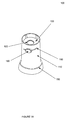
- FIG. 1A is an isometric top view of an embodiment of a dual polarizing hood
- FIG. 1B is an isometric side view of the dual polarizing hood of FIG. 1A ;
- FIG. 1C is an exploded view of the dual polarizing hood of FIGS. 1A and 1B ;
- FIG. 1D (section A-A) is an exploded view of the dual polarizing hood of FIGS. 1A and 1B along cross section A;
- FIG. 1E is a side exploded view of the dual polarizing hood of FIGS. 1A and 1B .
- FIG. 1F is a bottom view of the dual polarizing hood of FIGS. 1A and 1B ;
- FIG. 1G is a side view of the dual polarizing hood of FIGS. 1A and 1B ;
- FIG. 1H is a top view of the dual polarizing hood of FIGS. 1A and 1B ;
- FIG. 2 depicts a side cutaway view of the operation of an dual polarizing hood
- FIG. 3 is a block diagram illustrating a multisensory device imaging a target and interfacing with a video capture component
- FIG. 4 is a side view illustrating a handheld video examination camera in accordance with one embodiment of the invention.
- FIG. 5 is an exploded view further illustrating the handheld video examination camera of FIG. 4 ;
- FIG. 6 is an exploded view further illustrating a portion of the camera of FIG. 4 ;
- FIG. 7 further illustrates a portion of the handheld video examination camera of FIG. 4 .
- FIG. 8 is a side exploded view of a light-sensor construction in the camera of FIG. 5 ;
- FIG. 9 is a perspective view further illustrating the light-sensor construction of FIG. 8 ;
- FIG. 10 is a side view further illustrating the light-sensor construction of FIG. 8 ;
- FIG. 11 is a bottom view further illustrating the light assembly of FIG. 8 .
- the present invention provides a dual polarizing lens hood for at least one of digital still or digital video camera, and more specifically to a dual polarizing lens hood for a camera that has a light source collocated with the camera lens objective.
- a system for polarizing light provided by a light source via a first polarizer and further polarizing reflected light by a second polarizer, such that the provided light and the reflected light are each directed through the polarizing portion of the first and second polarizers one time.
- the dual polarizing hood 100 may comprise a hood body 110 , a polarizing window 120 , and a rotational window/polarizer 130 .
- the polarizing hood may also comprise a derm hood 150 , and a switch 160 for adjusting the polarization of the device.
- the hood body 110 is configured to provide structural support for the various polarizing hood 100 elements. Though it may be any suitable shape, in an embodiment, the exterior surface of hood body 110 is generally conical. Hood body 110 may be formed from a rigid material. In an embodiment, hood body is opaque. In various embodiments, at least a portion of hood body may be clear. The exterior diameter of hood body 110 is configured to gradually increases from the end of hood body 110 intended to be coupled to a lens 117 , to the opposite end 115 of hood body 110 . Hood body generally comprises an open internal cavity running from one end 117 of the polarizing hood to the other end 115 . Similar to the exterior surface of hood body 110 , and with reference to FIG. 1D , an exploded view of the polarizing hood of FIGS. 1A and 1B along cross section A-A, the interior cavity of hood body 110 , gradually increases from the end 117 to the opposite end 115 of hood body 110 .
- End 117 of hood body 110 may comprise features for coupling polarizing hood 100 to another object.
- These features for coupling may be threading, clips, grooves for receiving anchoring members, pressure fit, and the like. This coupling is intended to be suitably strong to retain the polarizing hood 100 to another object as desired and to allow for convenient decoupling of polarizing hood 100 from the object as desired, for instance, when polarization is not desired.
- Hood body 110 may comprise surface features to aid in gripping the polarizing hood 100 and/or coupling and decoupling the polarizing hood 100 from a still and/or video digital camera device, such as camera 301 .
- Hood body 110 may also comprise surface features to aid in retaining optional derm hood 150 .
- hood body 110 may comprise a raised lip 112 around at least a portion of end 115 which derm hood 150 may be press fit over.
- the raised lip 112 can be seen juxtaposed end 115 .
- a clear lens may be coupled to end 115 to prevent debris and other unwanted particles from entering end 115 .
- derm hood 150 may be made from a polymer, such as a medical grade polymer. Derm hood 150 may be any suitable shape; such as conical, elliptic cylinder, parabolic cylinder, hyperbolic cylinder or cylindrical. In an embodiment, with renewed reference to FIGS. 1A-1G , derm hood 150 is substantially cylindrical with an open interior. The interior dimension of derm hood 150 may substantially mirror the exterior surface dimensions of the end 115 of hood body 110 . As shown, derm hood 150 may be coupled to hood body 110 by elastically stretching derm hood 150 over raised lip 112 . In some embodiments, derm hood 150 is configured for one time use to promote sanitary and sterile objectives.
- derm hood 150 may be in contact with a surface such as the skin of a patient and replaced with a second derm hood 150 prior to contacting a second surface, such as the skin of a second patient.
- Derm hood 150 may cover end 115 of hood body 110 or it may cover the majority of the external surface of hood body 110 (not shown).
- Hood body 110 may comprise surface features to aid in positioning polarizing hood 100 .
- hood body 110 may be marked with one or more surface markings, such as an arrow or line to indicate 0 axis position, to aim hood body 110 and an associated camera.
- hood body 110 may comprise a slot opening 180 for a portion of rotational window/polarizer 130 to pass through (described in greater detail below).
- Hood body 110 may also comprise surface features to aid positioning rotational window/polarizer 130 .
- hood body 110 may be marked with one or more surface markings adjacent to and/or near slot opening 180 , such that a user may be able to select and note a preferred polarization setting. For instance, dashes at regular intervals with associated characters, such as numbers, to indicate degrees from the 0 axis position.
- Polarizing window 120 may comprise a polarizing filter.
- the polarizing filter may be a linear polarizing filter, circular polarizing filter, or reflecting polarizing filter.
- the linear polarizing filter may be dichroic. In its broadest sense the term dichroism may refer to the selective absorption of one of the two orthogonal components of an incident beam of light.
- the polarizing filter may be impregnated with a compound which makes the molecules conductive so they absorb light whose electric field is parallel to the molecular chains.
- the resultant polarizing filter blocks waves with electric fields along the molecular axes, and passes waves with perpendicular electric fields.
- the output is a beam which is linearly polarized along the preferred axis.
- a circular polarizer may include a linear polarizer on the front, which selects one polarization of light while rejecting another, followed by a quarter wave plate, which converts the selected polarization to circularly polarized light inside the camera, which works with most all types of cameras, because mirrors and beam-splitters split circularly polarized light the same way they split unpolarized light.
- Polarizing window 120 may be configured to have a substantially circular cross section sized to securably fit inside the interior of hood body 110 .
- polarizing window 120 is positioned with the center of its face perpendicular to the axis running through hood body 110 facing end 117 .
- the polarizing filter of polarizing window 120 may be oriented in any suitable orientation, such as with the 0 axis of the polarizing filter directed to the top of hood body 110 (e.g., twelve o'clock).
- polarizing window 120 may be oriented to optimally interact with known/or measured properties of the provided light source.
- the polarizing filter selected may be optimized based on the type of light source. For instance, a polarizing filter for white light (about 560 nm) may not be as efficient as for other light sources such as blue (480 nm), green (560 nm), and/or red (660 nm).
- the polarizing filter may comprise a multi-resistance coating, to help prevent scratches and repel dirt and water. This coating may also reduce flare and ghosting at the filter surface.
- the polarizing filter may be a neutral polarization filter with weather and/or dust sealing.
- polarizing window 120 comprises a polarizing portion and a non-polarizing portion.
- polarizing window 120 may comprise an opening 122 towards the center of polarizing window 120 to allow reflected light to reach the lens without passing through the polarizing filter of polarizing window 120 .
- Opening 122 may be a circular opening.
- the polarizing filter of polarizing window 120 may be oriented around at least a portion of the perimeter of polarizing window 120 .
- polarizing window 120 may comprise a clear non-polarizing lens 122 towards the center of polarizing window 120 to allow reflected light from end 115 to a provided lens without passing through a polarizing filter of polarizing window 120 .
- the polarizing filter of polarizing window 120 may be fitted in hood body 110 such that the polarizing filter portion of polarizing window 120 polarizes light emitted from a light source collocated with a lens, such as an embedded light, and does not polarize light reflected from end 115 to the lens.
- Rotational window/polarizer 130 may comprise a polarizing filter.
- the polarizing filter may be a linear polarizing filter, circular polarizing filter, or reflecting polarizing filter.
- Rotational window/polarizer 130 may be configured to have a substantially circular cross section.
- rotational window/polarizer 130 is positioned with the center of its face perpendicular to the axis running through hood body 110 facing end 115 .
- rotational window/polarizer 130 comprises a polarizing portion and a non-polarizing portion.
- rotational window/polarizer 130 may comprise a clear lens (e.g., the non-polarizing portion) towards perimeter of rotational window/polarizer 130 to allow light from a light source collocated with a lens, such as an embedded light, to reach end 115 without passing through the polarizing filter of rotational window/polarizer 130 .
- Rotational window/polarizer 130 may also comprise a small polarizing filter located towards the center of rotational window/polarizer 130 configured to filter reflected light entering end 115 .
- Rotational window/polarizer 130 may comprise an extension arm 135 configured to extend radially through slot opening 180 .
- Switch 160 may be coupled to a distal portion of extension arm 135 extending through slot opening 180 .
- Rotational window/polarizer 130 may be manually rotated about the center axis of hood body 110 . Stated another way, in an embodiment, rotational window/polarizer 130 may be rotated with respect to the objective of a lens. This rotation may allow a user to select a preferable level of polarization.
- Switch 160 may comprise a surface feature such as a tab or marking which when used with the surface markings adjacent to and/or near slot opening 180 on hood body 110 to align rotational window/polarizer 130 in a preferable orientation.
- the intensity of the reflected light may be adjusted by rotating rotational window/polarizer 130 .
- window and polarizer 130 is depicted as being manually adjusted, it should be appreciated that rotational window/polarizer 130 may be mechanically and/or automatically rotated in response to electrical control signaling from a controller. It should also be appreciated, that in accordance with Brewster's law, at a certain orientation of rotational window/polarizer 130 , all light may be absorbed by polarizing filter 132 .
- the polarizing portion of polarizing window 120 substantially overlaps the non-polarizing portion of rotational window/polarizer 130 , and the non-polarizing portion of polarizing window 120 substantially overlaps the polarizing portion of rotational window/polarizer 130 relative to light passing parallel through the center axis of hood body 110 .
- Internal retaining ring 140 may be coupled to hood body 110 .
- Internal retaining ring 140 may be configured to retain rotational window/polarizer 130 in position.
- polarizing window 120 may be permanently or semi-permanently coupled in place within hood body 110 using an epoxy, glue, press fit or other suitable securing mechanism.
- internal retaining ring 140 may be coupled in place within hood body 110 using an epoxy, glue, press fit or other suitable securing mechanism.
- rotational window/polarizer 130 may be sandwichably positioned between internal retaining ring 140 and polarizing window 120 such that rotational window/polarizer 130 may be rotated about the central axis of hood body 110 (as allowed by the movement of extension arm 135 in slot 180 ).
- a lubricant may be added to the edge of rotational window/polarizer 130 to aid in rotation. It should be appreciated that though rotational window/polarizer 130 is depicted as being closest to end 117 with respect to polarizing window 120 , the polarizing hood would operate as intended if polarizing window 120 was located closest to end 117 with respect to rotational window/polarizer 130 .
- FIGS. 1F-1H are bottom, side and top views (respectively) of the polarizing hood 100 .
- FIG. 1G is a side view of the dual polarizing hood of FIGS. 1A and 1B .
- FIG. 1H is a top view of the dual polarizing hood of FIGS. 1A and 1B .
- the polarizing hood 100 is directed towards an object of interest, (in this case, a hand).
- Light 210 from a light source embedded with a lens, such as on the same plane as a lens or near a lens is configured to be directed into end 117 .
- the light 210 is directed through the polarizing filter portion of polarizing window 120 .
- This polarizing/filtering of the provided light source creates controlled beams/rays of light to illuminate a target object.
- polarized light the details of a specimen and/or object being illuminated, including its color, composition and structure which are normally invisible or difficult to discern using non-polarized light may be apparent.
- the polarized light is directed through the non-polarizing portion of rotational window/polarizer 130 (e.g., clear lens).
- the polarized light exits end 115 .
- the polarized light illuminates the object of interest.
- additional grades of polarizer may be implemented in polarizing hood 100 .
- various grades of polarizer may be implemented to pass different amounts of polarization.
- the light is configured to be at least partially reflected from the object of interest through end 115 towards end 117 .
- the reflected light 220 is directed through the polarizing filter portion 132 of rotational window/polarizer 130 .
- the polarized reflected light 220 is directed through the non-polarizing portion of polarizing window 120 (e.g. opening 122 ).
- the polarized reflected light passes through end 115 .
- the polarized reflected light is captured by a provided lens.
- a user may adjust the desired polarization level of the reflected light by rotating rotational window/polarizer 130 a desired amount by manipulating switch 160 .
- rotational window/polarizer 130 may be locked in a preferred orientation using switch 160 .
- switch 160 has a first position and a second position. While switch 160 is in a first position, rotational window/polarizer may rotate with freedom. In response to switch 160 being in the second position a force is place on the exterior of hood 110 and rotational window/polarizer 130 may be locked in a preferred orientation, until switch put back into the first position.
- Polarizing hood 100 may be suitably combined with aspects of a camera as disclosed in patent application Ser. No. 12/319,049, titled “System and Method for video Medical Examination and real time Transmission to remote Locations” filed Dec. 31, 2008.
- the camera 301 may be a small, handheld, high-resolution examination camera. This camera may be used in the medical and life science fields. Polarization in spectral topography can vastly improve histopathological studies.
- Camera 301 is durable, light-weight, easy-to-use, includes a snap-shot capability and is freeze-frame ready. Camera 301 can interface directly into any number of analog or digital video processing devices as needed.
- the block diagram 100 of FIG. 3 includes an examination video camera 301 having an optical end 305 and an interface end 303 comprising an optical sensor assembly 330 in electrical communication with a camera body 340 .
- Camera body 340 interfaces 350 a connection 360 which can be wired, optical, or wireless.
- Connection 360 provides data communication and, optionally, power to and from camera 301 .
- Optical/sensor assembly 330 includes a light producing assembly 500 ( FIG. 9 ) which provides illumination 210 .
- Assembly 500 may be axially aligned with a lens assembly and is positioned so as not to illuminate the lens assembly other than via light 220 reflected off target 320 and up through the lens assembly into camera 301 .
- the lens assembly may include a lens fixedly mounted inside a hollow lens barrel.
- Light 220 reflected from a target 320 is received and processed by optical/sensor assembly 330 , is relayed to the camera body 340 , and is transmitted to a video capture and/or processing component 370 .
- Optional attachments 310 can be mounted on the optical end of the camera body 140 , and may include for example polarizing hood 100 .
- FIG. 5 is a partial exploded view of the handheld video examination camera 301 , an optical/sensor assembly 330 , camera body 340 and housing.
- the optical sensor assembly 330 is shown in further detail and includes sensor/LED assembly 500 , a head, a lens barrel, and a window.
- LEDs 550 are mounted on LED board 540 and wires 530 each deliver electricity to an LED 550 .
- LED board 540 is secured adjacent spacer 520
- spacer 520 is secured adjacent sensor board 510 .
- Sensor 515 is mounted on board 510 .
- LEDs 550 or another desired light source can produce visible or non-visible light having any desired wavelength, including, for example, visible colors, ultraviolet light, or infrared light.
- the light source can produce different wavelengths of light and permit each different wavelength to be used standing alone or in combination with one or more other wavelengths of light.
- the light source can permit the brightness of the light produced to be adjusted.
- the light source can comprise 395 nM (UV), 860 nM (NIR), and white LEDs and can operated at several brightness levels such that a health care provider can switch from white light to a “woods” lamp environment at the touch of a control button on the camera 301 .
- the light source, or desired portions thereof can be turned on and off while camera 301 is utilized to examine a target. In some instances, it may be desirable to depend on the ambient light and to not produce light using a light source mounted in camera 301 . In which case reflected light 220 comprises ambient light and/or light from other than the light source collocated with the lens.
Landscapes
- Physics & Mathematics (AREA)
- General Physics & Mathematics (AREA)
- Optics & Photonics (AREA)
- Blocking Light For Cameras (AREA)
Abstract
Description
Claims (17)
Priority Applications (2)
| Application Number | Priority Date | Filing Date | Title |
|---|---|---|---|
| US13/246,590 US8588605B2 (en) | 2011-09-21 | 2011-09-27 | Dual polarizing hood |
| US14/049,826 US8774619B2 (en) | 2011-09-21 | 2013-10-09 | Dual polarizing hood |
Applications Claiming Priority (2)
| Application Number | Priority Date | Filing Date | Title |
|---|---|---|---|
| US201161537507P | 2011-09-21 | 2011-09-21 | |
| US13/246,590 US8588605B2 (en) | 2011-09-21 | 2011-09-27 | Dual polarizing hood |
Related Child Applications (1)
| Application Number | Title | Priority Date | Filing Date |
|---|---|---|---|
| US14/049,826 Continuation US8774619B2 (en) | 2011-09-21 | 2013-10-09 | Dual polarizing hood |
Publications (2)
| Publication Number | Publication Date |
|---|---|
| US20130071103A1 US20130071103A1 (en) | 2013-03-21 |
| US8588605B2 true US8588605B2 (en) | 2013-11-19 |
Family
ID=47880750
Family Applications (2)
| Application Number | Title | Priority Date | Filing Date |
|---|---|---|---|
| US13/246,590 Active - Reinstated 2031-11-24 US8588605B2 (en) | 2011-09-21 | 2011-09-27 | Dual polarizing hood |
| US14/049,826 Active US8774619B2 (en) | 2011-09-21 | 2013-10-09 | Dual polarizing hood |
Family Applications After (1)
| Application Number | Title | Priority Date | Filing Date |
|---|---|---|---|
| US14/049,826 Active US8774619B2 (en) | 2011-09-21 | 2013-10-09 | Dual polarizing hood |
Country Status (1)
| Country | Link |
|---|---|
| US (2) | US8588605B2 (en) |
Cited By (7)
| Publication number | Priority date | Publication date | Assignee | Title |
|---|---|---|---|---|
| US20120105400A1 (en) * | 2010-10-29 | 2012-05-03 | Mathew Dinesh C | Camera lens structures and display structures for electronic devices |
| US20140243685A1 (en) * | 2013-02-28 | 2014-08-28 | Canfield Scientific, Incorporated | Dermatoscope devices |
| US20160143519A1 (en) * | 2014-11-20 | 2016-05-26 | Globalmedia Group, Llc | Polarizing endoscopy system and method |
| US9458990B2 (en) | 2013-08-01 | 2016-10-04 | 3Gen, Inc. | Dermoscopy illumination device with selective polarization and orange light for enhanced viewing of pigmented tissue |
| US10298906B2 (en) * | 2016-08-18 | 2019-05-21 | Verily Life Sciences Llc | Dermal camera attachment |
| US10441379B2 (en) | 2017-12-28 | 2019-10-15 | 3Gen, Inc. | Multipurpose medical illuminator with magnification |
| US11395714B2 (en) | 2019-11-11 | 2022-07-26 | Dermlite Llc | Medical illuminator with variable polarization |
Families Citing this family (9)
| Publication number | Priority date | Publication date | Assignee | Title |
|---|---|---|---|---|
| US9476569B2 (en) * | 2014-05-20 | 2016-10-25 | King Abdulaziz City for Science and Technology (KACST) | Apparatus light pen and its use |
| CN105530783B (en) * | 2014-12-26 | 2016-10-12 | 比亚迪股份有限公司 | A kind of communication apparatus metal shell and preparation method thereof |
| US20160366316A1 (en) * | 2015-06-12 | 2016-12-15 | Htc Corporation | Skin analysis device and image capturing module thereof |
| FR3051341B1 (en) | 2016-05-18 | 2018-06-01 | Universite De Lorraine | MEDICAL WIRELESS DEVICE FOR ACQUIRING SKIN VIDEOS BIMODALITY WITH LIGHT CONTROL |
| CN108111743A (en) * | 2016-11-24 | 2018-06-01 | 中兴通讯股份有限公司 | The control method and shade of shade |
| US10710752B2 (en) * | 2018-10-16 | 2020-07-14 | The Boeing Company | System and method for inspecting aircraft windows |
| US11003048B1 (en) * | 2019-12-13 | 2021-05-11 | VG Technology Inc. | Polarized imaging apparatus for use with a mobile device |
| IT202100008582A1 (en) * | 2021-04-07 | 2022-10-07 | Roberto VAI | PHOTOGRAPHIC LAB EQUIPMENT |
| US12216384B1 (en) | 2022-03-22 | 2025-02-04 | Adam Khan | Dynamic lens filter and illuminated filter tray assembly |
Citations (13)
| Publication number | Priority date | Publication date | Assignee | Title |
|---|---|---|---|---|
| US2194523A (en) | 1936-04-18 | 1940-03-26 | Zelss Ikon Ag | Polarizing filter attachments |
| US3572905A (en) | 1968-04-10 | 1971-03-30 | Leitz Ernst Gmbh | Lens hood |
| US3759153A (en) | 1972-10-25 | 1973-09-18 | Polaroid Corp | Lens shade |
| US5198875A (en) | 1990-08-16 | 1993-03-30 | L'oreal | Device designed to assess the brightness of a surface more particularly of the skin |
| US6010450A (en) | 1998-06-29 | 2000-01-04 | Welch Allyn, Inc. | Measuring adapter for viewing instrument |
| US6032071A (en) | 1994-12-01 | 2000-02-29 | Norbert Artner | Skin examination device |
| US6104887A (en) | 1998-04-15 | 2000-08-15 | Asahi Kogaku Kogyo Kabushiki Kaisha | Lens hood |
| US6269227B1 (en) | 1999-05-27 | 2001-07-31 | Asahi Kogaku Kogyo Kabushiki Kaisha | Lens hood |
| US6389238B1 (en) * | 1999-03-24 | 2002-05-14 | Asahi Kogaku Kogyo Kabushiki Kaisha | Lens barrel |
| US6587711B1 (en) | 1999-07-22 | 2003-07-01 | The Research Foundation Of Cuny | Spectral polarizing tomographic dermatoscope |
| US7004599B2 (en) * | 2004-01-02 | 2006-02-28 | 3Gen, Llc. | Illuminated mirror employing cross and parallel polarization |
| US7167243B2 (en) * | 2003-03-07 | 2007-01-23 | 3Gen, Llc. | Dermoscopy epiluminescence device employing cross and parallel polarization |
| US20090189972A1 (en) | 2005-07-12 | 2009-07-30 | Harris Michael D | System and method for video medical examination and real time transmission to remote locations |
-
2011
- 2011-09-27 US US13/246,590 patent/US8588605B2/en active Active - Reinstated
-
2013
- 2013-10-09 US US14/049,826 patent/US8774619B2/en active Active
Patent Citations (14)
| Publication number | Priority date | Publication date | Assignee | Title |
|---|---|---|---|---|
| US2194523A (en) | 1936-04-18 | 1940-03-26 | Zelss Ikon Ag | Polarizing filter attachments |
| US3572905A (en) | 1968-04-10 | 1971-03-30 | Leitz Ernst Gmbh | Lens hood |
| US3759153A (en) | 1972-10-25 | 1973-09-18 | Polaroid Corp | Lens shade |
| US5198875A (en) | 1990-08-16 | 1993-03-30 | L'oreal | Device designed to assess the brightness of a surface more particularly of the skin |
| US6032071A (en) | 1994-12-01 | 2000-02-29 | Norbert Artner | Skin examination device |
| US6104887A (en) | 1998-04-15 | 2000-08-15 | Asahi Kogaku Kogyo Kabushiki Kaisha | Lens hood |
| US6010450A (en) | 1998-06-29 | 2000-01-04 | Welch Allyn, Inc. | Measuring adapter for viewing instrument |
| US6389238B1 (en) * | 1999-03-24 | 2002-05-14 | Asahi Kogaku Kogyo Kabushiki Kaisha | Lens barrel |
| US6269227B1 (en) | 1999-05-27 | 2001-07-31 | Asahi Kogaku Kogyo Kabushiki Kaisha | Lens hood |
| US6587711B1 (en) | 1999-07-22 | 2003-07-01 | The Research Foundation Of Cuny | Spectral polarizing tomographic dermatoscope |
| US7167243B2 (en) * | 2003-03-07 | 2007-01-23 | 3Gen, Llc. | Dermoscopy epiluminescence device employing cross and parallel polarization |
| US7167244B2 (en) * | 2003-03-07 | 2007-01-23 | 3Gen, Llc. | Dermoscopy epiluminescence device employing multiple color illumination sources |
| US7004599B2 (en) * | 2004-01-02 | 2006-02-28 | 3Gen, Llc. | Illuminated mirror employing cross and parallel polarization |
| US20090189972A1 (en) | 2005-07-12 | 2009-07-30 | Harris Michael D | System and method for video medical examination and real time transmission to remote locations |
Cited By (12)
| Publication number | Priority date | Publication date | Assignee | Title |
|---|---|---|---|---|
| US20120105400A1 (en) * | 2010-10-29 | 2012-05-03 | Mathew Dinesh C | Camera lens structures and display structures for electronic devices |
| US9143668B2 (en) * | 2010-10-29 | 2015-09-22 | Apple Inc. | Camera lens structures and display structures for electronic devices |
| US10009525B2 (en) | 2010-10-29 | 2018-06-26 | Apple Inc. | Camera lens structures and display structures for electronic devices |
| US20140243685A1 (en) * | 2013-02-28 | 2014-08-28 | Canfield Scientific, Incorporated | Dermatoscope devices |
| US10617305B2 (en) * | 2013-02-28 | 2020-04-14 | Canfield Scientific, Incorporated | Dermatoscope devices |
| US9458990B2 (en) | 2013-08-01 | 2016-10-04 | 3Gen, Inc. | Dermoscopy illumination device with selective polarization and orange light for enhanced viewing of pigmented tissue |
| US20160143519A1 (en) * | 2014-11-20 | 2016-05-26 | Globalmedia Group, Llc | Polarizing endoscopy system and method |
| US9775500B2 (en) | 2014-11-20 | 2017-10-03 | Globalmedia Group, Llc | Polarizing endoscopy system and method |
| US10201268B2 (en) * | 2014-11-20 | 2019-02-12 | Globalmedia Group, Llc | Polarizing endoscopy system and method |
| US10298906B2 (en) * | 2016-08-18 | 2019-05-21 | Verily Life Sciences Llc | Dermal camera attachment |
| US10441379B2 (en) | 2017-12-28 | 2019-10-15 | 3Gen, Inc. | Multipurpose medical illuminator with magnification |
| US11395714B2 (en) | 2019-11-11 | 2022-07-26 | Dermlite Llc | Medical illuminator with variable polarization |
Also Published As
| Publication number | Publication date |
|---|---|
| US8774619B2 (en) | 2014-07-08 |
| US20140036362A1 (en) | 2014-02-06 |
| US20130071103A1 (en) | 2013-03-21 |
Similar Documents
| Publication | Publication Date | Title |
|---|---|---|
| US8588605B2 (en) | Dual polarizing hood | |
| US7835074B2 (en) | Mini-scope for multi-directional imaging | |
| US9775500B2 (en) | Polarizing endoscopy system and method | |
| US5078469A (en) | Optical system which allows coincident viewing, illuminating and photographing | |
| WO2003047240A3 (en) | Universal security camera | |
| US11003048B1 (en) | Polarized imaging apparatus for use with a mobile device | |
| WO2016205950A1 (en) | Apparatus for imaging skin | |
| WO2007035472A3 (en) | Scheimpflug normalizer | |
| KR20070120038A (en) | Focusing assist device and focusing method of the lens unit | |
| DK1847873T3 (en) | Panoramic imaging device | |
| US5042930A (en) | Optical system which allows coincident viewing, illuminating and photographing | |
| CN107621692B (en) | Objective lens module and microscope | |
| EP3676532B1 (en) | Polarized illumination systems | |
| JP2011061371A (en) | Imaging device with tilt-adjustment mechanism | |
| KR200367917Y1 (en) | Iris identification camera module having stable actinomenter | |
| US11194228B2 (en) | Evidence capturing | |
| JPH02207401A (en) | Lighting system in enlarged image pickup device | |
| JP2022014412A (en) | Imaging apparatus | |
| CN113238351A (en) | Polarization type optical lens structure and imaging device | |
| JP2003098570A (en) | Endoscope | |
| US11333829B2 (en) | Medical imaging device with split image on common image sensor | |
| RU2008137979A (en) | METHOD FOR ANALYSIS OF PAINT AND COATING WITH PIGMENT EFFECT | |
| KR100565564B1 (en) | Anti-reflective shooting aid and photographing apparatus including the same | |
| JP2004240202A (en) | Handle pipe type endoscope in which direction of visual range is bent and fixed | |
| KR20110061466A (en) | Camera module |
Legal Events
| Date | Code | Title | Description |
|---|---|---|---|
| AS | Assignment |
Owner name: GLOBALMEDIA GROUP, LLC, ARIZONA Free format text: ASSIGNMENT OF ASSIGNORS INTEREST;ASSIGNOR:HARRIS, MICHAEL D.;REEL/FRAME:026977/0217 Effective date: 20110926 |
|
| AS | Assignment |
Owner name: SILICON VALLEY BANK, CALIFORNIA Free format text: SECURITY AGREEMENT;ASSIGNOR:GLOBALMEDIA GROUP, LLC;REEL/FRAME:030695/0741 Effective date: 20130625 |
|
| REMI | Maintenance fee reminder mailed | ||
| AS | Assignment |
Owner name: SILICON VALLEY BANK, CALIFORNIA Free format text: RELEASE BY SECURED PARTY;ASSIGNOR:GLOBALMEDIA GROUP, LLC;REEL/FRAME:044259/0989 Effective date: 20130625 |
|
| LAPS | Lapse for failure to pay maintenance fees |
Free format text: PATENT EXPIRED FOR FAILURE TO PAY MAINTENANCE FEES (ORIGINAL EVENT CODE: EXP.) |
|
| FP | Lapsed due to failure to pay maintenance fee |
Effective date: 20171119 |
|
| AS | Assignment |
Owner name: SILICON VALLEY BANK, CALIFORNIA Free format text: SECURITY INTEREST;ASSIGNOR:GLOBALMEDIA GROUP, LLC;REEL/FRAME:044643/0969 Effective date: 20180116 Owner name: GLOBALMEDIA GROUP, LLC, ARIZONA Free format text: RELEASE BY SECURED PARTY;ASSIGNOR:SILICON VALLEY BANK;REEL/FRAME:044643/0744 Effective date: 20180116 |
|
| PRDP | Patent reinstated due to the acceptance of a late maintenance fee |
Effective date: 20180214 |
|
| FEPP | Fee payment procedure |
Free format text: SURCHARGE, PETITION TO ACCEPT PYMT AFTER EXP, UNINTENTIONAL. (ORIGINAL EVENT CODE: M2558); ENTITY STATUS OF PATENT OWNER: SMALL ENTITY Free format text: PETITION RELATED TO MAINTENANCE FEES GRANTED (ORIGINAL EVENT CODE: PMFG) Free format text: PETITION RELATED TO MAINTENANCE FEES FILED (ORIGINAL EVENT CODE: PMFP) |
|
| MAFP | Maintenance fee payment |
Free format text: PAYMENT OF MAINTENANCE FEE, 4TH YR, SMALL ENTITY (ORIGINAL EVENT CODE: M2551) Year of fee payment: 4 |
|
| STCF | Information on status: patent grant |
Free format text: PATENTED CASE |
|
| MAFP | Maintenance fee payment |
Free format text: PAYMENT OF MAINTENANCE FEE, 8TH YR, SMALL ENTITY (ORIGINAL EVENT CODE: M2552); ENTITY STATUS OF PATENT OWNER: SMALL ENTITY Year of fee payment: 8 |