US8585657B2 - Dispensing fluid from an infusion pump system - Google Patents
Dispensing fluid from an infusion pump system Download PDFInfo
- Publication number
- US8585657B2 US8585657B2 US13/164,987 US201113164987A US8585657B2 US 8585657 B2 US8585657 B2 US 8585657B2 US 201113164987 A US201113164987 A US 201113164987A US 8585657 B2 US8585657 B2 US 8585657B2
- Authority
- US
- United States
- Prior art keywords
- drive wheel
- medicine
- pump device
- piston rod
- infusion pump
- Prior art date
- Legal status (The legal status is an assumption and is not a legal conclusion. Google has not performed a legal analysis and makes no representation as to the accuracy of the status listed.)
- Active, expires
Links
Images


Classifications
-
- A—HUMAN NECESSITIES
- A61—MEDICAL OR VETERINARY SCIENCE; HYGIENE
- A61M—DEVICES FOR INTRODUCING MEDIA INTO, OR ONTO, THE BODY; DEVICES FOR TRANSDUCING BODY MEDIA OR FOR TAKING MEDIA FROM THE BODY; DEVICES FOR PRODUCING OR ENDING SLEEP OR STUPOR
- A61M5/00—Devices for bringing media into the body in a subcutaneous, intra-vascular or intramuscular way; Accessories therefor, e.g. filling or cleaning devices, arm-rests
- A61M5/14—Infusion devices, e.g. infusing by gravity; Blood infusion; Accessories therefor
- A61M5/142—Pressure infusion, e.g. using pumps
- A61M5/145—Pressure infusion, e.g. using pumps using pressurised reservoirs, e.g. pressurised by means of pistons
- A61M5/1452—Pressure infusion, e.g. using pumps using pressurised reservoirs, e.g. pressurised by means of pistons pressurised by means of pistons
- A61M5/1456—Pressure infusion, e.g. using pumps using pressurised reservoirs, e.g. pressurised by means of pistons pressurised by means of pistons with a replaceable reservoir comprising a piston rod to be moved into the reservoir, e.g. the piston rod is part of the removable reservoir
Definitions
- This document relates to an infusion pump system, such as a medical infusion pump system.
- a medical infusion pump device may be used to deliver a medicine to a patient as part of a medical treatment.
- the medicine that is delivered by the infusion pump device can depend on the condition of the patient and the desired treatment plan.
- infusion pump devices have been used to deliver insulin to the vasculature of diabetes patients so as to regulate blood-glucose levels.
- the infusion pump devices may include a drive system in which a threaded rod is advanced by a drive wheel.
- the threaded rod can be advanced toward a plunger that acts upon a medicine in a reservoir to dispense a portion of the medicine.
- significant pressure changes e.g., an impact such as a drop on the floor, a significant change in altitude and ambient pressure, or the like
- a dose of the medicine could be inadvertently dispensed to the user.
- the threaded rod of the drive system, the drive wheel of the drive system, or a combination thereof may undergo a slight shift or movement relative to the medicine reservoir such that an increment of the medicine is inadvertently forced out from the medicine reservoir.
- an infusion pump system include a drive system that advances a piston rod to dispense medicine to a user.
- the drive system can be configured to reliably dose selected amounts of medicine to the user while also reducing the likelihood of inadvertent dispensing of medicine in response to impacts or pressure changes exerted upon the infusion pump system.
- the drive system may include a piston rod that is forwardly advanced in response to rotation of a drive wheel, which is spring-biased in an axial direction toward a predetermined axial position.
- the piston rod can also be biased to remain in position during the instances when the pump device is subjected to an impact or pressure change, thereby reducing the likelihood that the piston rod will undergo an axial shift relative to the medicine reservoir and inadvertently cause dispensation of the medicine.
- an infusion pump device may include a pump housing that defines a space to receive a medicine.
- the infusion pump device may also include a drive system to dispense a medicine from the pump housing when the medicine is received in the space.
- the drive system may comprise an electrically powered actuator and a drive wheel that rotates in response to movement of the electrically powered actuator.
- the drive system may also include a piston rod that is engaged with the drive wheel. The piston rod may advance in a longitudinally forward direction toward the space to receive the medicine in response to rotation of the drive wheel.
- the drive wheel may be spring-biased in an axial direction that is generally opposite to the longitudinally forward direction so that the drive wheel is urged toward a selected axial position in the pump housing.
- an infusion pump device may include a pump housing that defines a space to receive a medicine.
- the infusion pump device may include a drive system to dispense the medicine from the pump housing when the medicine is received in the space.
- the drive system may include a piston rod that is advanced in a longitudinally forward direction toward the space to dispense the medicine.
- the drive system may further include a drive wheel that rotates to advance the piston rod.
- the drive system may include a bias member that biases the drive wheel in an axial direction that is generally opposite to the longitudinally forward direction so that the drive wheel is urged toward a particular axial position in the pump housing.
- the drive system may further include a ratchet wheel that is incrementally rotated in a forward direction to rotate the drive wheel and thereby advance the piston rod.
- the drive system may include a movable pawl that engages the ratchet wheel.
- the movable pawl may be adjustable from a reset position to a forward position so as to incrementally rotate the ratchet wheel in the forward direction.
- a spring device may urge the movable pawl to adjust from the reset position to the forward position.
- the drive system may include an actuator assembly that acts upon the movable pawl to force the movable pawl to the reset position and that reverses to permit the movable pawl to adjust from the reset position to the forward position.
- the various embodiments of the infusion pump device described herein can be configured to removably attach to a controller device so as to form a system to controllably dispense medicine.
- the infusion pump device may have a first electrical connector to mate with a second electrical connector of the controller device.
- Particular embodiments include a method of dispensing medicine from an infusion pump device.
- the method may include rotating a drive wheel housed inside a pump housing of an infusion pump device in response to movement of an electrically powered actuator housed inside the pump housing.
- the method may also include, in response to rotating the drive wheel, advancing a piston rod in a longitudinally forward direction toward a space defined by the pump housing that is configured to receive a medicine.
- the drive wheel may be urged by a bias member in an axial direction that is generally opposite to the longitudinally forward direction and toward a predetermined position in the pump housing.
- some embodiments of the infusion pump system may be configured to reduce the likelihood that the piston rod will undergo an axial shift relative to the medicine reservoir and inadvertently cause dispensation of the medicine.
- certain embodiments of an infusion pump system may accurately and incrementally dispense fluid from the pump device in a controlled manner.
- some embodiments of the infusion pump system may have a compact configuration of drive system components. For example, one or more components of the drive system may be nested inside another component.
- the infusion pump system may be configured to be portable, wearable, and (in some circumstances) concealable. For example, a user can conveniently wear the infusion pump system on the user's skin under clothing or can carry the pump device in the user's pocket (or other portable location) while receiving the medicine dispensed from the pump device.
- FIG. 1 is an exploded perspective view of an infusion pump system in accordance with some embodiments.
- FIG. 2 is a perspective view of the infusion pump system of FIG. 1 in a detached state.
- FIG. 3 is a perspective view of an infusion pump system, in accordance with some embodiments.
- FIGS. 4-5 are perspective views of the pump device of FIGS. 1-2 being discarded and the controller device of FIGS. 1-2 being reused with a new pump device.
- FIG. 6 is an exploded perspective view of a controller device for an infusion pump system, in accordance with some embodiments.
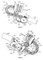
- FIG. 7 is an exploded perspective view of a pump device for an infusion pump system, in accordance with some embodiments.
- FIGS. 8-11 are perspective views of components of a drive system of the pump device of FIG. 7 .
- FIG. 12 is an exploded perspective view of components of the drive system of FIG. 7 .
- FIG. 13 is an exploded perspective view of components of the drive system and a portion of a housing of the pump device of FIG. 7 .
- FIG. 14 is a perspective view of components of the drive system and a portion of the housing of the pump device of FIG. 7 .
- FIG. 15 is a cross-sectional view of the components of the drive system and the portion of the housing of FIG. 14 .
- an infusion pump system 10 can include a pump device 100 and a controller device 200 that communicates with the pump device 100 .
- the pump device 100 in this embodiment includes a housing structure 110 that defines a cavity 116 in which a fluid cartridge 120 can be received.
- the pump device 100 also can include a cap device 130 to retain the fluid cartridge 120 in the cavity 116 of the housing structure 110 .
- the pump device 100 can include a drive system that advances a plunger 125 in the fluid cartridge 120 so as to dispense fluid therefrom.
- some embodiments of the drive system can be advantageously configured to reliably dose selected amounts of fluid to a user while also reducing the likelihood of inadvertent dispensing of medicine in response to impacts or pressure changes exerted upon the pump device 100 .
- the controller device 200 communicates with the pump device 100 to control the operation of the drive system.
- the controller device 200 , the pump device 100 (including the cap device 130 ), and the fluid cartridge 120 are assembled together, the user can (in some embodiments) conveniently wear the infusion pump system 10 on the user's skin under clothing, in a pouch clipped at the waist (e.g., similar to a cell phone pouch), or in the user's pocket while receiving the fluid dispensed from the pump device 100 .
- the controller device 200 may be configured as a reusable component that provides electronics and a user interface to control the operation of the pump device 100 .
- the pump device 100 can be a disposable component that is disposed of after a single use.
- the pump device 100 can be a “one time use” component that is thrown away after the fluid cartridge 120 therein is exhausted. Thereafter, the user can removably attach a new pump device 100 ′ (having a new medicine cartridge 120 ′) to the reusable controller device 200 for the dispensation of fluid from a new fluid cartridge 120 ′. Accordingly, the user is permitted to reuse the controller device 200 (which may include complex or valuable electronics, as well as a rechargeable battery) while disposing of the relatively low-cost pump device 100 after each use.
- a pump system 10 can provide enhanced user safety as a new pump device 100 ′ (and drive system therein) is employed with each new fluid cartridge 120 ′.
- the pump device 100 is configured to removably attach to the controller device 200 in a manner that provides a secure fitting, an overall compact size, and a reliable electrical connection that is resistant to water migration.
- the controller device 200 can include a housing 210 having a number of features that mate with complementary features of the pump housing 110 .
- the controller device 200 can removably attach with the pump device 100 in a generally side-by-side configuration.
- the compact size permits the infusion pump system 10 to be discrete and portable (as described below in connection with FIG. 3 ).
- at least one of the pump device 100 or the controller device 200 can include a release member that facilitates an easy-to-use detachment and replacement process.
- the pump system 10 can be a medical infusion pump system that is configured to controllably dispense a medicine from the cartridge 120 .
- the fluid cartridge 120 can contain a medicine 126 to be infused into the tissue or vasculature of a targeted individual, such as a human or animal patient.
- the pump device 100 can be adapted to receive a medicine cartridge 120 in the form of a carpule that is preloaded with insulin or another medicine for use in the treatment of Diabetes (e.g., Byetta®, Symlin®, or others).
- a medicine cartridge 120 may be supplied, for example, by Eli Lilly and Co. of Indianapolis, Ind.
- the fluid cartridge 120 may have other configurations.
- the fluid cartridge 120 may comprise a reservoir that is integral with the pump housing structure 110 (e.g., the fluid cartridge 120 can be defined by one or more walls of the pump housing structure 110 that surround a plunger to define a reservoir in which the medicine is injected or otherwise received).
- the pump device 100 can include one or more structures that interfere with the removal of the medicine cartridge 120 after the medicine cartridge 120 is inserted into the cavity 116 .
- the pump housing structure 110 can include one or more retainer wings (not shown in FIG. 1 ) that at least partially extend into the cavity 116 to engage a portion of the medicine cartridge 120 when the medicine cartridge 120 is installed therein. Such a configuration may facilitate the “one-time-use” feature of the pump device 100 .
- the retainer wings can interfere with attempts to remove the medicine cartridge 120 from the pump device 100 , thus ensuring that the pump device 100 will be discarded along with the medicine cartridge 120 after the medicine cartridge 120 is emptied, expired, or otherwise exhausted.
- the pump device 100 can operate in a tamper-resistant and safe manner because the pump device 100 can be designed with a predetermined life expectancy (e.g., the “one-time-use” feature in which the pump device is discarded after the medicine cartridge 120 is emptied, expired, or otherwise exhausted).
- a predetermined life expectancy e.g., the “one-time-use” feature in which the pump device is discarded after the medicine cartridge 120 is emptied, expired, or otherwise exhausted.
- the controller device 200 can be removably attached to the pump device 100 so that the two components are mechanically mounted to one another in a fixed relationship. Such a mechanical mounting can form an electrical connection between the removable controller device 200 and the pump device 100 .
- the controller device 200 can be in electrical communication with a portion of a drive system (not shown in FIG. 1 ) of the pump device 100 .
- the pump device 100 can include a drive system that causes controlled dispensation of the medicine or other fluid from the cartridge 120 .
- the drive system incrementally advances a piston rod (not shown in FIG. 1 ) longitudinally into the cartridge 120 so that the fluid is forced out of an output end 122 .
- a septum 121 FIG.
- Power signals such as signals from the rechargeable battery 245 (refer to FIG. 6 ) of the controller device 200 and from the power source 310 (refer to FIG. 7 ) of the pump device 100 may also be passed between the controller device 200 and the pump device 100 .
- the pump device 100 can include an electrical connector 118 (e.g., having conductive pads, pins, and the like) that is exposed to the controller device 200 and that mates with a complementary electrical connector (refer to connector 218 in FIG. 2 ) on the adjacent face of the controller device 200 .
- the electrical connectors 118 and 218 provide the electrical communication between the control circuitry (refer, for example, to FIG. 6 ) housed in the controller device 200 and at least a portion of the drive system or other components of the pump device 100 .
- the electrical connectors 118 and 218 can permit the transmission of electrical control signals to the pump device 100 and the reception of feedback signals (e.g., sensor signals) from particular components within the pump device 100 .
- the electrical connectors 118 and 218 may similarly facilitate transmission of one or more power signals from the rechargeable battery pack 245 to the pump device 100 , where the signals may be used to provide power to components of the pump device 100 , or to transmit one or more power signals from the power source 310 to the controller device, where the signals may be used to charge the rechargeable battery 245 or to power components of the controller device 200 .
- the controller device 200 can include a user interface 220 that permits a user to monitor the operation of the pump device 100 .
- the user interface 220 can include a display device 222 and one or more user-selectable buttons (e.g., several buttons 224 are shown in the embodiment of FIG. 1 ).
- the display device 222 can include an active area in which numerals, text, symbols, images, or a combination thereof can be displayed.
- the display device 222 can be used to communicate a number of settings or menu options for the infusion pump system 10 .
- the user may press one or more of the buttons to shuffle through a number of menus or program screens that show particular settings and data (e.g., review data that shows the medicine dispensing rate, the total amount of medicine dispensed in a given time period, the amount of medicine scheduled to be dispensed at a particular time or date, the approximate amount of medicine remaining in the cartridge 120 , or the like).
- the user can adjust the settings or otherwise program the controller device 200 by pressing one or more buttons of the user interface 220 .
- the user may press one or more of the buttons to change the dispensation rate of insulin or to request that a bolus of insulin be dispensed immediately or at a scheduled, later time.
- the display device 222 may also be used to communicate information regarding remaining battery life.
- the user can readily operate the user interface 220 of the controller device 200 , which is removably attached to the pump device 100 , without the requirement of locating and operating a separate monitoring module.
- the controller device 200 can be removably attached to the pump device 100 in a side-by-side arrangement.
- the pump device 100 may be moved in a longitudinal direction (e.g., refer to direction 219 in FIG. 4 ) toward the controller device 200 until the complementary features connect and secure the separate components in the side-by-side arrangement.
- the controller device 200 can include a controller housing structure 210 having a number of features that are configured to mate with complementary features of the pump housing structure 110 so as to form a releasable mechanical connection.
- the pump housing structure 110 can include a barrel 111 that mates with a complementary barrel channel 211 of the controller housing 210 .
- the pump device 100 and the controller device 200 can be mounted to one another so that the assembled system 10 is resistant to water migration both into the pump housing structure 110 and the controller housing structure 210 .
- Such a configuration can also provide water-resistant protection for the electrical connection between the pump device 100 and the controller device 200 .
- the sensitive internal components in the controller device 200 and the pump device 100 can be reliably protected from water migration if the user encounters water (e.g., rain, incidental splashing, and the like) while using the pump system 10 .
- the infusion pump system 10 can be configured to be portable and can be wearable and concealable.
- a user can conveniently wear the infusion pump system 10 on the user's skin (e.g., skin adhesive) underneath the user's clothing or carry the pump device 100 in the user's pocket (or other portable location) while receiving the medicine dispensed from the pump device 100 .
- the pump system 10 is shown in FIG. 3 as being held in a user's hand 5 so as to illustrate an exemplary size of the system 10 in accordance with some embodiments.
- This embodiment of the infusion pump system 10 is compact so that the user can wear the portable infusion pump system 10 (e.g., in the user's pocket, connected to a belt clip, adhered to the user's skin, or the like) without the need for carrying and operating a separate module.
- the cap device 130 of the pump device 100 can be configured to mate with an infusion set 146 .
- the infusion set 146 can be a tubing system that connects the infusion pump system 10 to the tissue or vasculature of the user (e.g., to deliver medicine into the tissue or vasculature under the user's skin)
- the infusion set 146 can include a flexible tube 147 that extends from the pump device 100 to a subcutaneous cannula 149 that may be retained by a skin adhesive patch (not shown) that secures the subcutaneous cannula 149 to the infusion site.
- the skin adhesive patch can retain the infusion cannula 149 in fluid communication with the tissue or vasculature of the patient so that the medicine dispensed through the tube 147 passes through the cannula 149 and into the user's body.
- the cap device 130 can provide fluid communication between the output end 122 ( FIG. 1 ) of the medicine cartridge 120 and the tube 147 of the infusion set 146 .
- the infusion pump system 10 can be pocket-sized so that the pump device 100 and controller device 200 can be worn in the user's pocket or in another portion of the user's clothing.
- the user may desire to wear the pump system 10 in a more discrete manner. Accordingly, the user can pass the tube 147 from the pocket, under the user's clothing, and to the infusion site where the adhesive patch can be positioned.
- the pump system 10 can be used to deliver medicine to the tissues or vasculature of the user in a portable, concealable, and discrete manner.
- the infusion pump system 10 can be configured to adhere to the user's skin directly at the location in which the skin is penetrated for medicine infusion.
- a rear surface 102 ( FIG. 2 ) of the pump device 100 can include a skin adhesive patch so that the pump device 100 can be physically adhered to the skin of the user at a particular location.
- the cap device 130 can have a configuration in which medicine passes directly from the cap device 130 into an infusion cannula 149 that is penetrated into the user's skin.
- the user can temporarily detach the controller device 200 (while the pump device 100 remains adhered to the skin) so as to view and interact with the user interface 220 .
- the infusion pump system 10 can be operated such that the pump device 100 is a disposable, non-reusable component while the controller device 200 is a reusable component.
- the pump device 100 may be configured as a “one-time-use” device that is discarded after the medicine cartridge is emptied, expired, or otherwise exhausted.
- the pump device 100 can be designed to have an expected operational life of about 1 day to about 30 days, about 1 day to about 20 days, about 1 to about 14 days, or about 1 day to about 7 days—depending on the volume of medicine in the cartridge 120 , the dispensation patterns that are selected for the individual user, and other factors.
- a medicine cartridge 120 containing insulin can have an expected usage life of about 7 days after the cartridge is removed from a refrigerated state and the septum 121 is punctured.
- the dispensation pattern selected by the user can cause the insulin to be emptied from the medicine cartridge 120 before the 7-day period. If the insulin is not emptied from the medicine cartridge 120 after the 7-day period, the remaining insulin can become expired sometime thereafter. In either case, the pump device 100 and the medicine cartridge 120 therein can be collectively discarded after exhaustion of the medicine cartridge 120 (e.g., after being emptied, expired, or otherwise not available for use).
- the controller device 200 may be reused with subsequent new pump devices 100 ′ and new medicine cartridges 120 ′.
- the control circuitry, the user interface components, the rechargeable battery pack 245 , and other components that may have relatively higher manufacturing costs can be reused over a longer period of time.
- the controller device 200 can be designed to have an expected operational life of about 1 year to about 7 years, about 2 years to about 6 years, or about 3 years to about 5 years—depending on a number of factors including the usage conditions for the individual user.
- the user can be permitted to reuse the controller device 200 (which can include complex or valuable electronics, and a rechargeable battery pack) while disposing of the relatively low-cost pump device 100 after each use.
- Such a pump system 10 can provide enhanced user safety as a new pump device 100 ′ (and drive system therein) is employed with each new medicine cartridge 120 ′.
- the same controller device 200 can be reused with a new pump device 100 ′ having a new medicine cartridge 120 ′ retained therein, and the previously used pump device 100 , including the exhausted medicine cartridge, can be discarded in a discard bin 20 .
- the new pump device 100 ′ ( FIG. 4 ) can have a similar appearance, form factor, and operation as the previously used pump device 100 , and thus the new pump device 100 ′ can be readily attached to the controller device 200 for controlled dispensation of medicine from the new medicine cartridge 120 ′.
- the user can prepare the new pump device 100 ′ for use with the controller device 200 .
- the user may insert the new medicine cartridge 120 ′ in the cavity 116 of the new pump device 100 ′ and then join the cap device 130 to the pump housing to retain the new medicine cartridge 120 ′ therein (refer, for example, to FIG. 1 ).
- the tubing 147 of the infusion set 146 is not shown in FIG. 4 , it should be understood that the tubing 147 can be attached to the cap device 130 prior to the cap device 130 being joined with the housing 110 .
- a new infusion set 146 can be connected to the cap device 130 so that the tubing 147 can be primed (e.g., a selected function of the pump device 100 controlled by the controller device 200 ) before attaching the cannula's adhesive patch to the user's skin.
- the new medicine cartridge 120 ′ may be filled with medicine such that the plunger 125 is not viewable through the barrel 111 .
- the new pump device 100 ′ can be removably attached to the controller device 200 to assemble into the infusion pump system 10 for delivery of medicine to the user.
- the guided motion in the longitudinal direction 219 provides the user with a convenient “one-movement” process to attach the pump device 100 ′ and the controller device 200 .
- the user can readily slide the pump device 100 ′ and the controller device 200 toward one another in a single movement (e.g., in the longitudinal direction 219 ) that causes both a physical connection and an electrical connection.
- the infusion pump system 10 can permit users to readily join the pump device 100 ′ and the controller device 200 without compound or otherwise difficult hand movements—a feature that can be particularly beneficial to child users or to elderly users.
- the controller device 200 houses a number of components that can be reused with a series of successive pump devices 100 .
- the controller device 200 can include controller circuitry 240 and a rechargeable battery pack 245 , each arranged in the controller housing 210 .
- rechargeable battery pack 245 may provide electrical energy to components of controller circuitry 240 , other components of the controller device (e.g., a display device 222 and other user interface components, sensors, or the like), or to components of the pump device 100 .
- Controller circuitry 240 may be configured to communicate control or power signals to the drive system of the pump device 100 , or to receive power or feedback signals from the pump device 100 .
- the user interface 220 of the controller device 200 can include input components and/or output components that are electrically connected to the controller circuitry 240 .
- the user interface 220 can include the display device 222 having an active area that outputs information to a user and buttons 224 that the user can use to provide input.
- the display device 222 can be used to communicate a number of settings or menu options for the infusion pump system 10 .
- the controller circuitry 240 can receive input commands from a user's button selections and thereby cause the display device 222 to output a number of menus or program screens that show particular settings and data (e.g., review data that shows the medicine dispensing rate, the total amount of medicine dispensed in a given time period, the amount of medicine scheduled to be dispensed at a particular time or date, the approximate amount of medicine remaining the cartridge 120 , the amount of battery life remaining, or the like).
- the controller circuitry 240 can be programmable to cause the controller circuitry 240 to change any one of a number of settings for the infusion pump system 10 .
- the user may provide one or more instructions to adjust a number of settings for the operation of the infusion pump system 10 .
- Such settings may be stored in one or more memory devices arranged in the controller circuitry 240 .
- the pump device 100 can include a drive system 300 that is controlled by the controller device 200 .
- the drive system 300 can incrementally dispense fluid in a controlled manner from cartridge 120 inserted into the pump device 100 .
- the pump device 100 may include a connector circuit 318 to facilitate the transfer of signals to and from the electrical connector 118 .
- the connector circuit 318 in the pump device 100 may include a memory device that can store data regarding the pump device 100 and its operational history.
- the electrical connector 118 of the pump device 100 can mate with the connector 218 ( FIG. 2 ) of the controller device 200 so that electrical communication can occur between the pump device 100 and the controller device 200 .
- the connector circuit 318 can operate as a passageway to transmit electrical control signals from the controller circuitry 240 of the controller device 200 to the drive system 300 .
- the connector circuit 318 can also operate as a passageway for the electrical power from a power source 310 housed in the pump device 300 to pass to the controller device 200 for recharging of the rechargeable battery 245 .
- the connector circuit 318 can operate as a passageway for feedback signals from the drive system 300 to the controller circuitry 240 of the controller device 200 .
- the pump device 100 houses the drive system 300 and the power source 310 .
- the power source 310 may comprise an alkaline battery cell, such as a 1.5 Volt “AAA” alkaline battery cell, which is contained in a dedicated space of the pump housing structure 110 .
- the power source 310 may be capable of transmitting electrical energy to the controller device 200 when the pump device 100 is attached to the controller device 200 , via connectors 118 and 218 as described above.
- the power source 310 may be used to charge the rechargeable battery pack 245 when the pump device 100 is attached to the controller device 200 .
- the power source 310 is used to provide energy to the drive system 300 of the pump device 100 , and also to electronic components of the controller device 200 .
- the power source 310 may provide the energy to power all aspects of the infusion pump system 10 .
- the rechargeable battery 245 housed in the controller 200 may provide the energy to power all aspects of the infusion pump system 10 .
- the rechargeable battery 245 and the power source 310 may each be responsible for powering particular aspects of the infusion pump system 10 .
- the rechargeable battery 245 may provide the energy to supplement the energy provided by the power source 310 to power aspects of the infusion pump system.
- the drive system 300 may include a number of components, such as an electrically powered actuator (e.g., reversible motor 320 or the like), a drive wheel 360 , a bearing 365 , a flexible piston rod 370 , a piston rod guide 363 , and a plunger engagement device 375 .
- the reversible motor 320 drives a gear system ( FIGS. 8-11 ) to cause the rotation of the drive wheel 360 that is coupled with bearing 365 (refer to FIG. 15 ).
- the drive wheel 360 may include a central aperture with an internal thread pattern (refer to FIG. 15 ), which mates with an external thread pattern on the flexible piston rod 370 .
- the interface of the threaded portions of the drive wheel 360 and flexible piston rod 370 may be used to transmit force from the drive wheel to the piston rod 370 .
- the drive wheel 360 is the driver while the flexible piston rod 370 is the driven member.
- the rotation of the drive wheel 360 can drive the flexible piston rod 370 forward in a linear longitudinal direction.
- the drive system 300 (and/or pump housing structure 110 ) may include features to constrain the flexible piston rod 370 from rotating about its longitudinal axis as it is urged to do when acted upon by the rotation of the drive wheel 360 .
- the flexible piston rod 370 is constrained from rotating, the transmission of force from the internal threads of the drive wheel 360 to the external threads of the flexible piston rod translates to a longitudinal advancement of the flexible piston rod as the drive wheel rotates.
- the piston rod guide 363 is one example of a structure that can constrain the flexible piston rod 370 from rotating when the piston rod 370 is acted upon by the rotation of the drive wheel 360 .
- one or more components of the drive system can be spring-biased toward an anchor position in the pump housing 110 so as to reduce the likelihood of an inadvertent dispensing of medicine resulting from, for example, an impact to the pump device 100 .
- the drive wheel 360 can be biased toward a generally fixed axial position relative to the pump housing structure 110 so that the drive wheel 360 (and the piston rod 370 engaged therewith) are not necessarily shifted relative to the pump housing 110 in response to an impact (e.g., dropping the pump device 100 on the floor).
- the pump housing includes bearing abutment shoulders 113 , which are integrally formed with the pump housing structure 110 .
- the outer race of the bearing 365 can be urged into physical contact with the bearing abutment shoulders 113 by a bias force from a bias member 380 ( FIGS. 13 and 15 ).
- the bias member 380 FIGS. 13 and 15
- the bias member 380 can be a spring that urges the drive wheel 360 and the bearing 365 in an axial direction that is generally opposite to the forward longitudinal direction of the piston rod 370 (e.g., the forward direction of the piston rod 370 when advanced to dispense medicine).
- Such a configuration may provide a generally consistent and robust axial anchor position of the drive wheel 360 within the pump housing structure 110 .
- the flexible piston rod 370 can be incrementally advanced toward the medicine cartridge 120 so as to dispense the medicine from the pump device 100 .
- the drive system 300 may also include an electrically powered actuator (e.g., reversible motor 320 or the like) that is coupled to a guided pusher arm 325 ( FIGS. 9-11 ), which is used to adjust a ratchet mechanism 330 to a reset position.
- a spring device 350 ( FIGS. 9-11 ) stores potential energy when the ratchet mechanism 330 is adjusted to the reset position and thereafter drives the ratchet mechanism 330 to a forward position to advance the piston rod 370 and dispense the medicine.
- the motor 320 can be decoupled from the ratchet mechanism 330 during the drive step.
- the reversible motor 320 can be used to shift the ratchet mechanism to a reset position, but the motor 320 does not drive the ratchet mechanism 330 to the forward position.
- the controller device 200 can communicate control signals to the pump device 100 for activating the drive system 300 or other components of the pump device 100 .
- the controller device 200 can include a controller housing structure 210 ( FIGS. 1-2 ) that is configured to mate with a complementary portion of the pump housing structure 110 so as to form a mechanical connection.
- the electrical connector 118 of the pump device 100 can mate with the corresponding electrical connector 218 of the controller device 200 .
- the electrical connector 118 is in communication with the connector circuit 318 ( FIG. 7 ).
- the connector circuit 318 may be a simple and inexpensive circuit so as to facilitate a low-cost pump device 100 that is disposable.
- the connector circuit 318 can be in electrical communication with one or more components housed in the pump device 100 , such as the motor 320 , the power source 310 , one or more sensor devices, or a combination thereof.
- the connector circuit 318 facilitates electrical communication with the removable controller device 200 ( FIGS. 1-2 ).
- the controller device 200 is capable of transmitting electrical signals to the pump device 100 and is capable of receiving feedback signals (e.g., sensor signals) from the components in the pump device 100 .
- Some components of the drive system 300 can be retained by the pump housing 110 ( FIG. 7 ).
- the motor 320 , the flexible piston rod 370 , the bearing 365 , the drive wheel 360 , the guide 363 , and the plunger engagement device 375 can be assembled into and retained by the pump housing 110 ( FIG. 7 ).
- a locking pawl 342 ( FIGS. 9-11 ) is integrally formed with the pump housing 110 so as to align with a portion of the ratchet mechanism 330 when the ratchet mechanism 330 is assembled into the pump housing 110 .
- the parts of the pump housing 110 are assembled ( FIG. 7 ), they can align and retain the ratchet mechanism 330 and other components of the drive system 300 .
- the assembled pump housing 110 can permit the desired motion of the components of the drive system 300 while reducing the likelihood of “backlash” movement (e.g., partial reverse rotation or movement of the drive components) or component dislodgement (which might otherwise occur, for example, when the pump device 100 is dropped to the ground).
- “backlash” movement e.g., partial reverse rotation or movement of the drive components
- component dislodgement which might otherwise occur, for example, when the pump device 100 is dropped to the ground.
- the reversible motor 320 is used to shift the ratchet mechanism 330 to the reset position, yet the motor 320 can be decoupled from the ratchet mechanism 330 during the drive step that causes dispensation of medicine.
- the motor 320 can be used to act upon the pusher arm 325 , which is guided along a predetermined path in a guide slot 328 .
- the guide slot 328 is integrally formed in an inner wall of the pump housing 110 (shown schematically in FIGS. 9-11 ), and the pusher arm 325 includes a slider pin 326 that mates with the guide slot 328 .
- FIG. 7 depicts the drive system 300 mounted to the pump housing 110 of the pump device 100
- FIG. 8 shows a similar view with the pump housing 110 removed for purposes of illustrating components of the drive system 300 ).
- the spring device 350 provides the energy for the drive step that advances the piston rod 370 and dispenses medicine, but the drive step may occur over a period of time that is greater than the relatively quick retraction of the pusher arm 325 to the first position. In such circumstances, the pusher arm 325 may be temporarily separated from the ratchet mechanism 330 , thereby causing the motor to be decoupled from the ratchet mechanism 330 during the drive step. Accordingly, the drive system 300 can provide an efficient process for accurately and reliably dispensing medicine in a manner that conserves battery life. Moreover, the drive system 300 may comprise few, if any, high-cost actuator components or electronics, thereby facilitating the production of a disposable and reliable pump device 100 .
- the electrically powered actuator may be in the form of the motor 320 having a rotatable output shaft 321 .
- the motor 320 is reversible in that it can receive signals that cause the output shaft 321 to rotate in a first rotational direction or in a second, opposite rotational direction.
- a suitable motor 320 is a coreless DC motor with reversible rotation capabilities.
- the operation of the motor 320 can be controlled by a control device (e.g., removable control device 200 as described in connection with FIGS. 1-2 or the like) via electrical signals communicated through the electrical connector 118 .
- a gear system 322 may be coupled to the motor 320 so that actuation by the motor 320 causes the pusher arm 325 to act upon the ratchet mechanism 330 or to decouple from the ratchet mechanism 330 .
- the gear system 322 includes a worm gear 323 and a gear reduction assembly comprising spur gears 324 a , 324 b , and 324 c .
- the pusher arm 325 can be pivotably coupled to the gear 324 c so that partial rotation of the gear 324 c causes the pusher arm to reciprocate within the guide slot 328 . Accordingly, rotation of the motor 320 in a first direction can be translated into an advancement force to the pusher arm 325 .
- the advancement force on the pusher arm 325 is applied to a pawl member 335 , which (in this embodiment) causes the pawl member 335 to pivot to a reset position (refer to FIG. 10 ).
- rotation of the motor 320 in a second direction can be translated into an retraction force to the pusher arm 325 , which can cause the pusher arm 325 to be separated from the pawl member 335 during the drive step (refer to FIG. 11 ).
- the motor 320 , the gear system 322 , and the pusher arm 325 can collectively operate as an actuator assembly that provides a reliable and consistent adjustment of the ratchet mechanism 330 during a reset step (refer to FIG. 10 ).
- this actuator assembly e.g., the motor 320 , the gear system 322 , and the pusher arm 325
- the motion path of the pusher arm 325 can be configured to provide an efficient mechanical advantage orientation during the desired motion of the adjustable pawl member 335 .
- the pusher arm 325 is directed by a guide slot 328 formed in the pump housing 110 (shown schematically in FIGS. 9-11 ).
- the pusher arm 325 includes the slider pin 326 that is received within the guide slot 328 during assembly. The portion of the pusher arm 325 proximate the slider pin 326 can abut against the pawl member 335 when the pusher arm is advanced.
- a second end of the pusher arm (proximate the slider pin 326 ) is directed by the guide slot 328 .
- the orientation of the pusher arm 325 relative to the guide slot 328 can be configured to provide an efficient mechanical advantage for the pushing force applied by the pusher arm 325 during the desired motion of the adjustable pawl member 335 .
- the ratchet mechanism 330 includes the pawl member 335 and a ratchet body 340 , which in this embodiment is a ratchet wheel having a number of teeth along its circumferential surface.
- the ratchet wheel 340 is coupled with a worm gear 345 , and incremental rotation of the ratchet wheel 340 causes rotation of a drive wheel 360 (due to engagement with the worm gear 345 ).
- the pawl member 335 is adjustable between a reset position (refer to FIG. 10 ) and a forward position (refer to FIG. 9 ).
- the motor 320 may be activated to advance the pusher arm 325 (guided by the guide slot 328 ), and the pusher arm 325 then applies a pushing force that adjusts the pawl member 335 to the reset position in which the pawl member 335 grabs a new tooth of the ratchet wheel 340 (refer to FIG. 10 ).
- the adjustable pawl member 335 is pivotably coupled about the axis of an axle (refer to FIGS. 9-11 ) that receives the ratchet wheel 340 and the worm gear 345 .
- the spring device 350 is also coupled to the pawl member 335 so as to urge the pawl member 335 toward the forward position (refer to FIG. 9 ).
- the spring device 350 is in the form of a coil extension spring that is fixed to the pump housing 110 (not shown in FIGS. 8-11 ) at a first end portion 352 and that is engaged with the pawl member 335 at a second end portion 354 .
- the spring device 350 when the pawl member 335 is adjusted to the reset position, the spring device 350 is in tension and stores potential energy that urges the pawl member 335 to return to the forward position (refer to FIG. 9 ) and thereby drive the ratchet wheel 340 in a forward rotational direction.
- a locking pawl 342 ( FIGS. 9-11 ) can be used to prevent the ratchet wheel 340 from reverse motion.
- the locking pawl 342 can flex or otherwise adjust to permit the incremental forward rotation of the ratchet wheel 340 .
- the adjustable pawl member 335 can adjust from the forward position (refer to FIG. 9 ) to the reset position (refer to FIG. 10 ) to engage a new tooth of the ratchet wheel 340 while the ratchet wheel 340 remains in position due to the locking pawl 342 .
- the drive system 300 can employ a set of location sensors to indicate when the pawl member 335 has reach the reset position or the forward position.
- these sensors can be optical, magnetic, or contact-type sensors.
- the sensors may be capable of transmitting signals that indicate when the location of one of the gears in the gear system 322 , the pusher arm 325 , or the pawl member 335 is detected. Such sensor signals may be transmitted to the motor 320 , to the controller device 200 ( FIGS. 1-2 ), or a combination thereof.
- the pawl member 335 may be equipped with an electrically conductive contact that engages a first contact-type sensor when moved to the reset position and that engages a second contact-type sensor when moved to the forward position.
- the first and second contact-type sensors can electrically communicate with the motor 320 , the controller device 200 , or both when the pawl member reaches the reset and forward positions. These signals may be used to indicate when the motor 320 should cease rotation or reverse rotation.
- the ratchet wheel 340 can be integrally formed with the worm gear 345 so that the incremental rotation of the ratchet wheel 340 is translated to the worm gear 345 .
- Such rotation of the worm gear 345 causes rotation of the drive wheel 360 .
- the drive wheel 360 can include a central aperture with an internal thread pattern (refer to FIG. 15 ), which mates with an external thread pattern 374 (refer to FIGS. 9-11 ) on the piston rod segments 372 .
- the incremental motion provided by the motor 320 , the pusher arm 325 , and the ratchet mechanism 330 causes the drive wheel 360 to incrementally rotate, which in turn translates to a longitudinal advancement of the flexible piston rod 370 .
- the piston rod 370 may undergo only forward or positive longitudinal displacement as a result of drive system 300 .
- the drive system 300 substantially hinders the piston rod 370 from retracting or “backing up” in response to fluid pressure in the medicine cartridge 120 or other reversal forces.
- the flexible piston rod 370 can be retracted only upon destruction of the pump device 100 (e.g., to disengage the drive wheel 360 or the ratchet mechanism 330 ).
- the non-retractable piston rod configuration may facilitate a “one time use” disposable pump device, thereby reducing the likelihood of failure due to non-intended repeated use of the disposable pump device 100 .
- the flexible piston rod 370 can comprise a plurality of rod segments 372 serially connected by hinge portions 373 so that the flexible piston rod 370 is adjustable from a curved shape to a noncurved shape.
- the plurality of segments 372 and the interconnecting hinge portions can be integrally formed in one piece from one or more moldable materials, including a number of polymer materials.
- the plurality of segments 372 comprise generally cylindrical segments that have an exterior thread pattern 374 along at least one cylindrical surface portion.
- the plunger engagement device 375 can be disposed at a forward end of the piston rod 370 so that the plunger engagement device 375 faces toward the medicine cartridge 120 .
- the flexible piston rod 370 can include an anti-rotation structure that hinders the piston rod 370 from rotating when acted upon by the rotation of the drive wheel 360 (thereby allowing the rotation of the drive wheel 360 to translate into a longitudinal motion of the piston rod 370 ).
- the flexible piston 370 includes longitudinal flat surfaces 371 extending along each of the segments 372 .
- the longitudinal flat surfaces 371 can engage complementary surfaces within an aperture of the piston rod guide 363 (refer to FIG. 15 ) proximate the drive wheel 360 so that the flexible piston rod 370 is hindered from rotating when the drive wheel 360 rotates.
- the longitudinal flat surfaces 371 on each segment 372 can align to form a key that slides within a mating keyway with complementary flat surface(s) defined by an aperture within piston rod guide 363 or pump housing 110 .
- the anti-rotation structure may include one or more longitudinal channels (with each channel capable of engaging an associated protrusion that acts as a key to hinder rotation while permitting longitudinal motion) or the like.
- the flexible piston rod 370 is adjustable from a curved shape to a noncurved shape, the overall length of the pump device can be reduced in some embodiments.
- the typical infusion pump requires a package or housing having a linear dimension sufficient to accommodate the length of the rigid piston rod when it is at its limit of travel in which it is fully withdrawn from the container or cylinder.
- the pump device 100 incorporating the flexible piston rod 370 can require less space than a similar device that houses a non-flexible, rigid rod.
- the incremental motion cycle of the drive system 300 may include rotation of the motor 320 so that the pusher arm 325 is advanced from a first position to act upon the pawl member 335 , and then retracted back to the first position. Such movement of the pusher arm 325 can cause the pawl member 335 to adjust from the forward position (refer to FIG. 9 ), to the reset position (refer to FIG. 10 ), and back to the forward position (under the driving force of the spring device 350 ).
- the adjustment of the pawl member 335 from the reset position to the forward position drives the ratchet wheel 340 and worm gear 345 , which incrementally rotates the drive wheel 360 and thereby advances the flexible piston rod 370 a longitudinal increment distance.
- the drive system 300 can advance the piston rod 370 a longitudinal increment distance of about 16 microns or less (about 4 microns to about 12 microns, about 5 microns to about 9 microns, and preferably about 6 microns to about 8 microns) for each incremental motion cycle of the ratchet mechanism 330 . Because each longitudinal increment distance for the piston rod 370 is relatively miniature, maintaining the axial position of the drive wheel 360 and the piston rod 370 can be useful. As described in more detail below in connection with FIGS.
- the drive system 300 can also be equipped with one or structures that reduce the likelihood of the piston rod 370 inadvertently shifting by a larger amount (e.g., about 20 microns or more, about 30 microns or more, and about 40 microns) in response an impact upon the pump housing.
- a larger amount e.g., about 20 microns or more, about 30 microns or more, and about 40 microns
- the pawl member 335 begins at the forward position with the pusher arm 325 retracted in a first position (e.g., the rest position in this embodiment).
- the adjustable pawl member 335 can be in this forward position, for example, because the drive system 300 previously completed a drive step at an earlier time.
- the motor 320 may begin to rotate in a first rotational direction that advances the pusher arm 325 to push against the pawl member 335 .
- Such movement of the pusher arm 325 causes a pushing force 327 that overcomes the bias of the spring device 350 and adjusts the pawl member 335 toward the reset position (e.g., the reset step).
- the reset position e.g., the reset step.
- the pawl member 335 is capable of engaging a new tooth of the ratchet wheel 340 .
- the locking pawl 342 prevents the ratchet wheel 340 from rotating in a reverse (non-forward) rotational direction while the adjustable pawl member 335 is shifting back to the reset position.
- Such an adjustment of the pawl member 335 back to the reset position creates a tension force 357 in the spring device 350 (as shown in FIG. 10 ), thereby storing potential energy to drive the adjustable pawl member 335 and ratchet wheel 340 in a forward rotational direction for the drive step.
- the motor 320 stops rotating in the first rotational direction and reverses to rotate in the second, opposite rotational direction. Such rotation in the second direction by the motor 320 causes the pusher arm 325 to promptly retract to the first position (while guided by the guide slot 328 ). As such, the spring device 350 begins to urge the pawl member 335 toward the forward position.
- the adjustable pawl 335 is driving the ratchet wheel 340 in the forward rotational direction, the potential energy of the spring device 350 is being translated to kinetic energy for the motion of the pawl member 335 and the ratchet wheel 340 .
- Such an adjustment of the pawl member 335 from the reset position to the forward position drives the ratchet wheel 340 and the integrally formed worm gear 345 .
- the incremental rotation of the worm gear 345 results in an incremental rotation by the drive wheel 360 , which advances the flexible piston rod 370 a longitudinal increment distance.
- Such an incremental advancement of the flexible piston rod 370 can cause a predetermined volume of fluid to be dispensed from the cartridge 120 .
- the motor 320 would begin by rotating in the first rotational direction so as to advance the pusher arm 325 yet again. This pattern of cycles may continue until the piston rod 370 has reached the limit of its longitudinal travel.
- the pusher arm 325 can be promptly retracted to the first position due to the reverse rotation of the motor 320 , the pawl member 335 is driven to the forward position ( FIG. 9 ) over a greater period of time.
- This period of time required for the drive step is affected by a number of factors, including the spring force from the spring device 350 , the fluid pressure inside the medicine cartridge 120 , and the like. Accordingly, the pusher arm 325 can be temporarily separated from the pawl member 335 when it is retracted to its first position, thereby causing the motor 320 to be decoupled from the ratchet mechanism 330 during the drive step.
- the portion of the pusher arm 325 proximate the slider pin 326 can become temporarily spaced apart by a distance 329 from the pawl member 335 while the pawl member 335 is being driven from the reset position ( FIG. 11 ) to the forward position ( FIG. 9 ).
- Such a configuration permits the motor 320 to expend a short burst of electrical energy to reset the ratchet mechanism 330 (e.g., during advancement of the pusher arm 325 ) while contributing no energy during the drive step to drive the ratchet mechanism 330 to the forward position for dispensation of medicine.
- the motor 320 can be decoupled from the ratchet mechanism 330 during the drive step, so only the spring device 350 expends energy over a period of time to drive the ratchet mechanism 330 to the forward position. Accordingly, the pump device 100 can reliably and accurately dispense dosages of medicine in a safe and energy efficient manner.
- the motor 320 is not required to draw energy from the power source 310 over an extended period of time (e.g., during the drive step in which the piston rod 370 is advanced to dispense medicine over a period of time). Instead, the motor 320 may draw upon the power source 310 during advancement of the pusher arm 325 to quickly reset the ratchet mechanism 330 and during the brief retraction of the pusher arm 325 .
- some components of the drive system 300 may be biased toward an anchor position in the pump housing 110 so as to reduce the likelihood of an inadvertent dispensing of fluid resulting from, for example, an impact to the pump device 100 .
- the drive wheel 360 can be biased toward a generally fixed axial position relative to the pump housing structure 110 so that the drive wheel 360 (and the piston rod 370 engaged therewith) are not necessarily shifted relative to the pump housing 110 in response to an impact (e.g., dropping the pump device 100 on the floor).
- the outer race of the bearing 365 can be forced into physical contact with the bearing abutment shoulders 113 (refer to FIGS.
- the bias member 380 can be a spring that urges the drive wheel 360 and the bearing 365 in an axial direction that is generally opposite to the forward longitudinal direction of the piston rod 370 (e.g., the forward direction of the piston rod 370 when advanced to dispense medicine).
- a bias member 380 FIGS. 13 and 15
- Such a configuration may provide a generally consistent and robust axial anchor position of the drive wheel 360 within the pump housing structure 110 .
- the bias member may be a compression spring 380 that generates an axial bias force 385 to urge the drive wheel 360 and bearing 365 toward the bearing abutment shoulders 113 (refer to FIGS. 7 , 14 - 15 ).
- Such a configuration can provide a pump device 100 wherein the relative positions of the drive wheel 360 and pump housing structure 110 are established and substantially maintained to reduce the likelihood an inadvertent dispensing of fluid, even in the event of an impact such as from dropping the pump device 100 onto the floor.
- the pump drive system components of one embodiment are shown in exploded views so as to depict the bias member 380 that may exert a spring-bias force to urge the drive wheel 360 and bearing 365 toward the shoulders 113 of the pump housing structure 110 .
- the bias member 380 may be disposed in a cavity defined by the drive wheel 360 and may be in the form of a compression spring positioned coaxially with the drive wheel 360 , the bearing 365 , at least a portion of the piston rod 370 , and the piston rod guide 363 . It should be understood from the description herein that, in alternative embodiments, other structures for biasing the piston rod 370 (and the components engaged therewith such as the drive wheel 360 ) relative to the pump housing structure 110 can be utilized.
- the bias member can be in the form of a spring-biased retainer ring that acts upon the bearing 365 .
- other types of springs such as leaf springs, wave washers, and the like, may be used as alternatives to the compression spring 380 shown in FIGS. 12-15 .
- FIGS. 14-15 the pump drive components of FIGS. 12-13 are therein shown in their assembled positions within the pump housing structure 110 .
- the compression spring 380 which was exposed in the exploded views of FIGS. 12-13 , is assembled into the axial cavity within the drive wheel 360 and is therefore not visible in FIG. 14 .
- the cross-sectional view of FIG. 15 provides a view of compression spring 380 disposed in the axial cavity between the gear teeth portion of the drive wheel 360 and the sleeve portion of the piston rod guide 363 .
- the compression spring 380 is disposed coaxially with the drive wheel 360 , the bearing 365 , at least a portion of the piston rod 370 , and the piston rod guide 363 .
- the radial position of the compression spring 380 may be maintained the inner diameter of the spring coils on one end being in contact with an outer diameter of a sleeve portion of the piston rod guide 363 .
- the compression spring is positioned radially outward of a portion of the guide 360 (which is fixed to the pump housing 110 ) and radially inward of a portion of the drive wheel 360 (which is rotatable relative to the pump housing 110 ).
- Such a configuration for nesting the compression spring 380 within other components of the drive system 300 can provide a compact assembly for the drive system 300 so as to further achieve an overall small infusion pump system 10 for user convenience.
- the piston rod guide 363 may be assembled within the pump housing structure 110 in a manner that functionally results in a fixed relationship between guide 363 and the housing 110 .
- the piston rod guide 363 may have protruding tabs on its perimeter that rigidly mate with corresponding grooves in structural features of the pump housing structure 110 . In this manner the piston rod guide 363 can be rigidly mounted to the pump housing structure 110 , and thereby serve as a base for the compression spring 380 that biases the drive wheel 360 and the bearing 365 away from the guide 363 .
- the compression spring 380 in this embodiment can be used to bias the drive wheel 360 and the bearing 365 against the bearing abutment shoulders 113 of the pump housing 110 .
- the drive wheel 360 and the bearing 365 can be press-fit together (as shown in FIG. 15 ) such that the outer diameter of the hub of drive wheel 360 may be assembled in contact with the inner diameter of the inner race of bearing 365 .
- the inner race of bearing 365 can rotate correspondingly.
- the outer race of bearing 365 may be assembled into a groove of the pump housing structure 110 , but due to manufacturing tolerances for the polymer materials of the pump housing 110 , the bearing 365 may not necessarily firmly abut against the shoulders 113 that are adjacent thereto.
- the compression spring 380 can be employed to bias the bearing 365 against the bearing abutment shoulders 113 in order to anchor that the axial position of the bearing 365 and drive wheel 360 relative to the pump housing structure 110 .
- the drive wheel 360 and the bearing 365 can be spring biased in an axial direction that is generally opposite of the forward longitudinal direction of the piston rod 370 , thereby reducing the likelihood of the drive wheel 360 (and the piston rod 370 engaged therewith) being axially shifted in the event of an impact such as from dropping the pump device 100 onto the floor.
- one end of the compression spring 380 can abut an axial face of the piston rod guide 363 , while the other end of the compression spring 380 can abut an axial face of the drive wheel 360 .
- piston rod guide 363 can be rigidly mounted with pump housing structure 110 . Therefore, in this embodiment, the end of the compression spring 380 in contact with the piston rod guide 363 is fixedly positioned relative to the pump housing structure 110 . As shown in FIG. 15 , one end of the compression spring 380 can abut an axial face of the piston rod guide 363 , while the other end of the compression spring 380 can abut an axial face of the drive wheel 360 .
- piston rod guide 363 can be rigidly mounted with pump housing structure 110 . Therefore, in this embodiment, the end of the compression spring 380 in contact with the piston rod guide 363 is fixedly positioned relative to the pump housing structure 110 . As shown in FIG.
- the other end of compression spring 380 can be in direct contact with the drive wheel 360 (which is assembled to the bearing 365 ), while exerting an axial bias force 385 to urge the drive wheel 360 an axial direction that is generally opposite of the forward longitudinal direction of the piston rod 370 , thereby urging the outer race of the bearing 365 into contact with the bearing abutment shoulders 113 .
- bearing 365 is therefore exposed to a thrust force from the compression spring 380 acting via the drive wheel 360 .
- the bias exerted by the compression spring 380 may therefore provide a generally constant axial position of the drive wheel 360 and bearing 365 relative to the pump housing structure 110 , even in the event of an impact such as from dropping the pump device 100 onto the floor. Because, as previously explained, the drive wheel 360 controls the lateral position of the flexible piston rod 370 that is coupled to the plunger engagement device 375 that controls the position of the plunger 125 of the medicine cartridge 120 , the compression spring 380 can exert a spring-bias force to axially bias the bearing 365 and drive wheel 360 toward a predetermined anchor position within the pump housing structure 110 to thereby reduce the likelihood of an inadvertent dispensing of fluid due to an impact or change in pressure.
Landscapes
- Health & Medical Sciences (AREA)
- Vascular Medicine (AREA)
- Engineering & Computer Science (AREA)
- Anesthesiology (AREA)
- Biomedical Technology (AREA)
- Heart & Thoracic Surgery (AREA)
- Hematology (AREA)
- Life Sciences & Earth Sciences (AREA)
- Animal Behavior & Ethology (AREA)
- General Health & Medical Sciences (AREA)
- Public Health (AREA)
- Veterinary Medicine (AREA)
- Infusion, Injection, And Reservoir Apparatuses (AREA)
Abstract
Description
Claims (20)
Priority Applications (3)
| Application Number | Priority Date | Filing Date | Title |
|---|---|---|---|
| US13/164,987 US8585657B2 (en) | 2011-06-21 | 2011-06-21 | Dispensing fluid from an infusion pump system |
| PCT/US2012/043558 WO2012177885A2 (en) | 2011-06-21 | 2012-06-21 | Dispensing fluid from an infusion pump system |
| EP12731866.5A EP2723424B1 (en) | 2011-06-21 | 2012-06-21 | Dispensing fluid from an infusion pump system |
Applications Claiming Priority (1)
| Application Number | Priority Date | Filing Date | Title |
|---|---|---|---|
| US13/164,987 US8585657B2 (en) | 2011-06-21 | 2011-06-21 | Dispensing fluid from an infusion pump system |
Publications (2)
| Publication Number | Publication Date |
|---|---|
| US20120330270A1 US20120330270A1 (en) | 2012-12-27 |
| US8585657B2 true US8585657B2 (en) | 2013-11-19 |
Family
ID=46457082
Family Applications (1)
| Application Number | Title | Priority Date | Filing Date |
|---|---|---|---|
| US13/164,987 Active 2032-02-16 US8585657B2 (en) | 2011-06-21 | 2011-06-21 | Dispensing fluid from an infusion pump system |
Country Status (3)
| Country | Link |
|---|---|
| US (1) | US8585657B2 (en) |
| EP (1) | EP2723424B1 (en) |
| WO (1) | WO2012177885A2 (en) |
Cited By (4)
| Publication number | Priority date | Publication date | Assignee | Title |
|---|---|---|---|---|
| US20170246402A1 (en) * | 2014-10-07 | 2017-08-31 | Westrock Dispensing Systems, Inc. | Indexing dose dispensing device |
| US10350349B2 (en) | 2014-05-20 | 2019-07-16 | Cequr Sa | Medicine delivery device with restricted access filling port |
| US10792425B2 (en) * | 2017-03-03 | 2020-10-06 | Jerry Joseph | Treatment system with automated cannula and sensor inserter, fluid delivery device, and drive mechanism for use therewith |
| WO2022180012A1 (en) * | 2021-02-24 | 2022-09-01 | B. Braun Melsungen Ag | Device for administering liquids comprising a damping element for absorbing external impact forces |
Families Citing this family (23)
| Publication number | Priority date | Publication date | Assignee | Title |
|---|---|---|---|---|
| US7959598B2 (en) | 2008-08-20 | 2011-06-14 | Asante Solutions, Inc. | Infusion pump systems and methods |
| USD669165S1 (en) * | 2010-05-27 | 2012-10-16 | Asante Solutions, Inc. | Infusion pump |
| USD669166S1 (en) * | 2010-05-27 | 2012-10-16 | Asante Solutions, Inc. | Infusion pump unit |
| USD669167S1 (en) * | 2010-05-27 | 2012-10-16 | Asante Solutions, Inc. | Controller for an infusion pump |
| US8454562B1 (en) | 2012-07-20 | 2013-06-04 | Asante Solutions, Inc. | Infusion pump system and method |
| US9457141B2 (en) | 2013-06-03 | 2016-10-04 | Bigfoot Biomedical, Inc. | Infusion pump system and method |
| US9561324B2 (en) * | 2013-07-19 | 2017-02-07 | Bigfoot Biomedical, Inc. | Infusion pump system and method |
| US10569015B2 (en) | 2013-12-02 | 2020-02-25 | Bigfoot Biomedical, Inc. | Infusion pump system and method |
| US10137246B2 (en) | 2014-08-06 | 2018-11-27 | Bigfoot Biomedical, Inc. | Infusion pump assembly and method |
| US9919096B2 (en) * | 2014-08-26 | 2018-03-20 | Bigfoot Biomedical, Inc. | Infusion pump system and method |
| US9878097B2 (en) | 2015-04-29 | 2018-01-30 | Bigfoot Biomedical, Inc. | Operating an infusion pump system |
| EP4591902A3 (en) | 2016-01-05 | 2025-11-26 | Insulet Corporation | Operating multi-modal medicine delivery systems |
| US10610643B2 (en) | 2016-01-14 | 2020-04-07 | Bigfoot Biomedical, Inc. | Occlusion resolution in medication delivery devices, systems, and methods |
| USD809134S1 (en) | 2016-03-10 | 2018-01-30 | Bigfoot Biomedical, Inc. | Infusion pump assembly |
| AU2017335762B2 (en) | 2016-09-27 | 2022-03-17 | Bigfoot Biomedical, Inc. | Medicine injection and disease management systems, devices, and methods |
| AU2017376111B2 (en) | 2016-12-12 | 2023-02-02 | Bigfoot Biomedical, Inc. | Alarms and alerts for medication delivery devices and related systems and methods |
| USD836769S1 (en) * | 2016-12-12 | 2018-12-25 | Bigfoot Biomedical, Inc. | Insulin delivery controller |
| USD839294S1 (en) | 2017-06-16 | 2019-01-29 | Bigfoot Biomedical, Inc. | Display screen with graphical user interface for closed-loop medication delivery |
| US11389088B2 (en) | 2017-07-13 | 2022-07-19 | Bigfoot Biomedical, Inc. | Multi-scale display of blood glucose information |
| USD921187S1 (en) * | 2018-07-05 | 2021-06-01 | Neuroderm, Ltd. | Pump device portion |
| USD921190S1 (en) * | 2018-07-05 | 2021-06-01 | Neuroderm, Ltd. | Pump device |
| USD921189S1 (en) * | 2018-07-05 | 2021-06-01 | Neuroderm, Ltd. | Pump device portion with vial adapters |
| USD921188S1 (en) * | 2018-07-05 | 2021-06-01 | Neuroderm, Ltd. | Pump device portion |
Citations (194)
| Publication number | Priority date | Publication date | Assignee | Title |
|---|---|---|---|---|
| US2605765A (en) | 1947-06-05 | 1952-08-05 | Kollsman Paul | Automatic syringe |
| GB747701A (en) | 1953-12-16 | 1956-04-11 | Lines Bros Ltd | Improvements in apparatus for controlling movements of model ships or other toys |
| US3886938A (en) | 1973-10-23 | 1975-06-03 | Scala Anthony | Power operated fluid infusion device |
| US4077405A (en) | 1975-03-26 | 1978-03-07 | Siemens Aktiengesellschaft | Apparatus for infusing liquids into human or animal bodies |
| US4231368A (en) | 1978-03-23 | 1980-11-04 | Michael Becker | Device for intramuscular injections, especially of insulin |
| US4265241A (en) | 1979-02-28 | 1981-05-05 | Andros Incorporated | Implantable infusion device |
| US4300554A (en) | 1979-02-22 | 1981-11-17 | Intermedicat Gmbh | Portable infusion apparatus |
| US4313439A (en) | 1980-03-24 | 1982-02-02 | Biotek, Inc. | Automated, spring-powered medicament infusion system |
| US4398908A (en) | 1980-11-28 | 1983-08-16 | Siposs George G | Insulin delivery system |
| US4435173A (en) | 1982-03-05 | 1984-03-06 | Delta Medical Industries | Variable rate syringe pump for insulin delivery |
| US4443218A (en) | 1982-09-09 | 1984-04-17 | Infusaid Corporation | Programmable implantable infusate pump |
| US4493704A (en) | 1982-11-29 | 1985-01-15 | Oximetrix, Inc. | Portable fluid infusion apparatus |
| US4529401A (en) | 1982-01-11 | 1985-07-16 | Cardiac Pacemakers, Inc. | Ambulatory infusion pump having programmable parameters |
| US4850817A (en) | 1987-12-01 | 1989-07-25 | Pacesetter Infusion, Ltd. | Mechanical drive system for a medication infusion system |
| GB2218831A (en) | 1988-05-17 | 1989-11-22 | Mark John Newland | Personal medical apparatus |
| FR2585252B1 (en) | 1985-07-26 | 1990-06-15 | Gazuit Ste Nle Electronique | SYRINGE DRIVER |
| US5045064A (en) | 1990-06-01 | 1991-09-03 | Infusaid, Inc. | Constant pressure implantable pump reservoir |
| US5088981A (en) | 1985-01-18 | 1992-02-18 | Howson David C | Safety enhanced device and method for effecting application of a therapeutic agent |
| US5190522A (en) | 1989-01-20 | 1993-03-02 | Institute Of Biocybernetics And Biomedical Engineering P.A.S. | Device for monitoring the operation of a delivery system and the method of use thereof |
| US5209230A (en) | 1990-10-19 | 1993-05-11 | Nellcor Incorporated | Adhesive pulse oximeter sensor with reusable portion |
| US5250027A (en) | 1991-10-08 | 1993-10-05 | Sherwood Medical Company | Peristaltic infusion device with backpack sensor |
| US5261882A (en) | 1993-04-26 | 1993-11-16 | Sealfon Andrew I | Negator spring-powered syringe |
| US5314412A (en) | 1991-04-17 | 1994-05-24 | Novo Nordisk A S | Manifold for a two barrel syringe |
| US5335994A (en) | 1988-10-04 | 1994-08-09 | G.I.R. | Temperature monitoring device containing at least one element of an alloy which memorizes its shape |
| US5338157A (en) | 1992-09-09 | 1994-08-16 | Pharmacia Deltec, Inc. | Systems and methods for communicating with ambulatory medical devices such as drug delivery devices |
| US5342180A (en) | 1992-11-17 | 1994-08-30 | Ivac Corporation | Pump mechanism having a drive motor with an external rotor |
| US5395340A (en) | 1993-03-15 | 1995-03-07 | Lee; Tzium-Shou | Infusion pump and a method for infusing patients using same |
| US5411487A (en) | 1992-12-07 | 1995-05-02 | Castagna; John F. | Hypodermic syringe with automatic needle cover |
| EP0580723B1 (en) | 1991-04-18 | 1995-10-25 | Novo Nordisk A/S | Infuser |
| US5545143A (en) | 1993-01-21 | 1996-08-13 | T. S. I. Medical | Device for subcutaneous medication delivery |
| US5551850A (en) | 1994-03-09 | 1996-09-03 | Baxter International Inc. | Pump chamber and valve assembly |
| US5569186A (en) | 1994-04-25 | 1996-10-29 | Minimed Inc. | Closed loop infusion pump system with removable glucose sensor |
| EP0496141B1 (en) | 1991-01-22 | 1997-04-02 | Eli Lilly And Company | Multiple dose injection pen |
| US5626566A (en) | 1991-10-18 | 1997-05-06 | Novo Nordisk A/S | Large dose pen |
| US5637095A (en) | 1995-01-13 | 1997-06-10 | Minimed Inc. | Medication infusion pump with flexible drive plunger |
| US5665065A (en) | 1995-05-26 | 1997-09-09 | Minimed Inc. | Medication infusion device with blood glucose data input |
| US5741216A (en) | 1992-04-10 | 1998-04-21 | Novo Nordisk A/S | Pressure monitor |
| US5772635A (en) | 1995-05-15 | 1998-06-30 | Alaris Medical Systems, Inc. | Automated infusion system with dose rate calculator |
| US5816306A (en) | 1993-11-22 | 1998-10-06 | Giacomel; Jeffrey A. | Shape memory alloy actuator |
| US5852803A (en) | 1992-03-20 | 1998-12-22 | Chips International, Inc. | Apparatus, system and method for recording and/or retrieving audio information |
| US5919167A (en) | 1998-04-08 | 1999-07-06 | Ferring Pharmaceuticals | Disposable micropump |
| US5925018A (en) | 1994-11-14 | 1999-07-20 | Cma/Microdialysis Ab | Infusion and microdialysis pump |
| US5928201A (en) | 1996-07-05 | 1999-07-27 | Novo Nordisk A/S | Dose setting device |
| US5947934A (en) | 1996-09-13 | 1999-09-07 | Novo Nordisk A/S | Dose display for an injection syringe |
| US5951530A (en) | 1996-04-24 | 1999-09-14 | Novo Nordisk A/S | Injection needle |
| US5957889A (en) | 1993-09-27 | 1999-09-28 | Novo Nordisk A/S | Displacement system for controlled infusion of a liquid |
| US5984894A (en) | 1991-04-18 | 1999-11-16 | Novo Nordisk A/S | Infuser |
| US5984897A (en) | 1993-04-01 | 1999-11-16 | Novo Nordisk A/S | Dispenser secured against reuse |
| US5997475A (en) | 1997-08-18 | 1999-12-07 | Solefound, Inc. | Device for diabetes management |
| US6003736A (en) | 1997-06-09 | 1999-12-21 | Novo Nordisk A/S | Device for controlled dispensing of a dose of a liquid contained in a cartridge |
| US6010485A (en) | 1996-09-20 | 2000-01-04 | Novo Nordisk A/S | Working cylinder |
| US6033377A (en) | 1997-02-04 | 2000-03-07 | Novo Nordisk A/S | Device for the administration of a liquid medicament suspension |
| US6045537A (en) | 1995-06-02 | 2000-04-04 | Novo Nordisk A/C | Syringe with automatically withdrawable of piston rod |
| US6074372A (en) | 1997-06-09 | 2000-06-13 | Novo Nordisk A/S | Dose setting mechanism and an injection syringe having such a dose setting mechanism |
| US6110149A (en) | 1996-09-13 | 2000-08-29 | Novo Nordisk A/S | Syringe |
| EP0612004B2 (en) | 1993-01-15 | 2000-10-04 | Alaris Medical Systems, Inc. | Configuration control system for configuring multiple biomedical devices |
| US6171276B1 (en) | 1997-08-06 | 2001-01-09 | Pharmacia & Upjohn Ab | Automated delivery device and method for its operation |
| EP1045146A3 (en) | 1999-04-14 | 2001-03-21 | Clemens Micheler | Medical dosing pump |
| US6231540B1 (en) | 1997-07-14 | 2001-05-15 | Novo Nordisk A/S | Injection member |
| US6248093B1 (en) | 1998-10-29 | 2001-06-19 | Minimed Inc. | Compact pump drive system |
| US6248067B1 (en) | 1999-02-05 | 2001-06-19 | Minimed Inc. | Analyte sensor and holter-type monitor system and method of using the same |
| US6248090B1 (en) | 1996-02-23 | 2001-06-19 | Novo Nordisk A/S | Syringe with electronic representation of parameters |
| US6277098B1 (en) | 1996-03-12 | 2001-08-21 | Novo Nordisk A/S | Injection device with electronic presentation of set doses |
| EP1136698A1 (en) | 2000-03-17 | 2001-09-26 | Seiko Epson Corporation | Temperature difference drive unit, and electric device, timepiece and light electrical appliance having the same |
| US6302855B1 (en) | 1998-05-20 | 2001-10-16 | Novo Nordisk A/S | Medical apparatus for use by a patient for medical self treatment of diabetes |
| US6302869B1 (en) | 1996-07-05 | 2001-10-16 | Novo Nordisk A/S | Syringe having a flexible piston rod |
| US20010041869A1 (en) | 2000-03-23 | 2001-11-15 | Causey James D. | Control tabs for infusion devices and methods of using the same |
| US20010056262A1 (en) | 1998-05-21 | 2001-12-27 | Oz Cabiri | Adhesive system for medical devices |
| US20020004651A1 (en) | 2000-04-13 | 2002-01-10 | Henrik Ljunggreen | Drug delivery device provided with a one-way mechanism |
| US20020040208A1 (en) | 2000-10-04 | 2002-04-04 | Flaherty J. Christopher | Data collection assembly for patient infusion system |
| US6375638B2 (en) | 1999-02-12 | 2002-04-23 | Medtronic Minimed, Inc. | Incremental motion pump mechanisms powered by shape memory alloy wire or the like |
| US6381496B1 (en) | 1999-10-01 | 2002-04-30 | Advanced Bionics Corporation | Parameter context switching for an implanted device |
| US6379339B1 (en) | 1996-09-13 | 2002-04-30 | Nova Nordisk A/S | Syringe |
| EP0721358B1 (en) | 1993-09-27 | 2002-05-08 | Novo Nordisk A/S | Displacement system for controlled infusion of a liquid |
| US6404098B1 (en) | 1999-04-15 | 2002-06-11 | Sony Corporation | Drive unit using shape memory alloy |
| US20020091358A1 (en) | 2000-10-05 | 2002-07-11 | Klitmose Lars Peter | Medication delivery device with bended piston rod |
| US6427088B1 (en) | 2000-01-21 | 2002-07-30 | Medtronic Minimed, Inc. | Ambulatory medical apparatus and method using telemetry system with predefined reception listening periods |
| US20020126036A1 (en) | 2000-12-21 | 2002-09-12 | Flaherty J. Christopher | Medical apparatus remote control and method |
| US6461331B1 (en) | 1999-05-21 | 2002-10-08 | Minimed Inc. | Device and method for infusion of small molecule insulin mimetic materials |
| US6474219B2 (en) | 2000-03-24 | 2002-11-05 | Novo Nordisk A/S | Flexible piston rod |
| US6485461B1 (en) | 2000-04-04 | 2002-11-26 | Insulet, Inc. | Disposable infusion device |
| US6508788B2 (en) | 2000-10-27 | 2003-01-21 | Novo Nordisk A/S | Medication delivery device with telescopic piston rod |
| US6524280B2 (en) | 2000-01-28 | 2003-02-25 | Noro Nordisk A/S | Dose setting limiter |
| US6533183B2 (en) | 2000-05-03 | 2003-03-18 | Novo Nordisk A/S | Coding of cartridges for an injection device |
| US20030055380A1 (en) | 2001-09-19 | 2003-03-20 | Flaherty J. Christopher | Plunger for patient infusion device |
| US6540672B1 (en) | 1998-12-09 | 2003-04-01 | Novo Nordisk A/S | Medical system and a method of controlling the system for use by a patient for medical self treatment |
| US6544229B1 (en) | 2000-05-01 | 2003-04-08 | Baxter International Inc | Linearly motile infusion pump |
| US6547764B2 (en) | 2000-05-31 | 2003-04-15 | Novo Nordisk A/S | Double pointed injection needle |
| US6551276B1 (en) | 1998-08-18 | 2003-04-22 | Medtronic Minimed, Inc. | External infusion device with remote programming bolus estimator and/or vibration alarm capabilities |
| US6554800B1 (en) | 2000-08-09 | 2003-04-29 | Medtronic Minimed, Inc. | Compact pump motor system and dispensing process |
| US6558320B1 (en) | 2000-01-20 | 2003-05-06 | Medtronic Minimed, Inc. | Handheld personal data assistant (PDA) with a medical device and method of using the same |
| US6558351B1 (en) | 1999-06-03 | 2003-05-06 | Medtronic Minimed, Inc. | Closed loop system for controlling insulin infusion |
| US20030088238A1 (en) | 2001-09-26 | 2003-05-08 | Poulsen Jens Ulrik | Modular drug delivery system |
| US6562011B1 (en) | 1998-07-08 | 2003-05-13 | Novo Nordisk A/S | Medication delivery device |
| US6569126B1 (en) | 1997-07-14 | 2003-05-27 | Novo Nordisk A/S | Cylinder ampoule |
| US6582404B1 (en) | 1999-09-16 | 2003-06-24 | Nna/S | Dose setting limiter |
| US6605067B1 (en) | 1998-11-20 | 2003-08-12 | Novo Nordisk A/S | Injection needle |
| US6613019B2 (en) | 2000-07-14 | 2003-09-02 | Novo Nordisk A/S | Liquid medication delivery device and a method of delivering an intended dose |
| US20030199825A1 (en) | 2002-04-23 | 2003-10-23 | Flaherty J. Christopher | Dispenser for patient infusion device |
| US6650951B1 (en) | 2000-06-19 | 2003-11-18 | International Business Machines Corporation | Method and insulin pump for providing a forgotten bolus warning |
| US20030216683A1 (en) | 2001-11-26 | 2003-11-20 | Nili-Med Ltd. | Drug delivery device and method |
| US6656158B2 (en) | 2002-04-23 | 2003-12-02 | Insulet Corporation | Dispenser for patient infusion device |
| US6659978B1 (en) | 1999-10-04 | 2003-12-09 | Seiko Instruments Inc. | Portable dosing apparatus |
| US6659980B2 (en) | 2000-03-29 | 2003-12-09 | Medtronic Minimed Inc | Methods, apparatuses, and uses for infusion pump fluid pressure and force detection |
| US6663602B2 (en) | 2000-06-16 | 2003-12-16 | Novo Nordisk A/S | Injection device |
| US6669669B2 (en) | 2001-10-12 | 2003-12-30 | Insulet Corporation | Laminated patient infusion device |
| US20040010207A1 (en) | 2002-07-15 | 2004-01-15 | Flaherty J. Christopher | Self-contained, automatic transcutaneous physiologic sensing system |
| US20040019325A1 (en) | 2002-07-29 | 2004-01-29 | Medrip Ltd. | Syringe Pump |
| US6690192B1 (en) | 2002-10-16 | 2004-02-10 | Pericom Semiconductor Corp. | Current-compensated CMOS output buffer adjusting edge rate for process, temperature, and Vcc variations |
| US6691043B2 (en) | 2001-08-28 | 2004-02-10 | Maxi-Med, Llc | Bolus calculator |
| US6692472B2 (en) | 2000-05-04 | 2004-02-17 | Novo Nordisk A/S | Injection device, a preassembled dose setting and injection mechanism for an injection device, and a method of assembling an injection device |
| US6692457B2 (en) | 2002-03-01 | 2004-02-17 | Insulet Corporation | Flow condition sensor assembly for patient infusion device |
| DE10236669A1 (en) | 2002-08-09 | 2004-02-19 | Korszak, Dieter | Pen for administration of insulin injections, comprising LED to display amount to be injected, acoustic repeat and timer to give visual and acoustic indications of dosages and timings |
| US6699218B2 (en) | 2000-11-09 | 2004-03-02 | Insulet Corporation | Transcutaneous delivery means |
| US6702779B2 (en) | 2000-08-18 | 2004-03-09 | Becton, Dickinson And Company | Constant rate fluid delivery device with selectable flow rate and titratable bolus button |
| US20040064088A1 (en) | 2002-09-30 | 2004-04-01 | William Gorman | Dispenser components and methods for patient infusion device |
| US20040064096A1 (en) | 2002-09-30 | 2004-04-01 | Flaherty J. Christopher | Components and methods for patient infusion device |
| US6716198B2 (en) | 2000-05-18 | 2004-04-06 | Novo Nordisk A/S | Injection device |
| US6715516B2 (en) | 2001-12-19 | 2004-04-06 | Novo Nordisk A/S | Method and apparatus for filling cartridges with a liquid |
| US6723072B2 (en) | 2002-06-06 | 2004-04-20 | Insulet Corporation | Plunger assembly for patient infusion device |
| US20040078028A1 (en) | 2001-11-09 | 2004-04-22 | Flaherty J. Christopher | Plunger assembly for patient infusion device |
| US20040087894A1 (en) | 2000-09-08 | 2004-05-06 | Flaherty J. Christopher | Devices, systems and methods for patient infusion |
| US6736796B2 (en) | 2001-11-26 | 2004-05-18 | Nili-Med Ltd. | Fluid drug delivery device |
| US6740072B2 (en) | 2001-09-07 | 2004-05-25 | Medtronic Minimed, Inc. | System and method for providing closed loop infusion formulation delivery |
| US6744350B2 (en) | 2002-02-28 | 2004-06-01 | Smiths Medical Md, Inc. | Insulin pump having missed meal bolus alarm |
| US6749587B2 (en) | 2001-02-22 | 2004-06-15 | Insulet Corporation | Modular infusion device and method |
| US20040116866A1 (en) | 2002-12-17 | 2004-06-17 | William Gorman | Skin attachment apparatus and method for patient infusion device |
| US6752787B1 (en) | 1999-06-08 | 2004-06-22 | Medtronic Minimed, Inc., | Cost-sensitive application infusion device |
| US20040153032A1 (en) | 2002-04-23 | 2004-08-05 | Garribotto John T. | Dispenser for patient infusion device |
| US6780156B2 (en) | 1998-09-08 | 2004-08-24 | Disetronic Licensing Ag | Module for a computer interface |
| US20040171983A1 (en) | 2003-02-24 | 2004-09-02 | Integrated Sensing Systems, Inc. | Fluid delivery system and sensing unit therefor |
| US6786890B2 (en) | 2002-01-25 | 2004-09-07 | Novo Nordisk A/S | Linear actuator and a medical delivery device comprising such linear actuator |
| US6799149B2 (en) | 2000-12-29 | 2004-09-28 | Medtronic, Inc. | Therapy management techniques for an implantable medical device |
| US6796970B1 (en) | 1997-06-17 | 2004-09-28 | Novo Nordisk A/S | Dose setting device |
| EP1177802B1 (en) | 2000-07-31 | 2004-09-29 | Becton Dickinson and Company | Wearable, self-contained drug infusion device |
| US6809653B1 (en) | 1998-10-08 | 2004-10-26 | Medtronic Minimed, Inc. | Telemetered characteristic monitor system and method of using the same |
| US20040220551A1 (en) | 2003-04-30 | 2004-11-04 | Flaherty J. Christopher | Low profile components for patient infusion device |
| US6827702B2 (en) | 2001-09-07 | 2004-12-07 | Medtronic Minimed, Inc. | Safety limits for closed-loop infusion pump control |
| US6830558B2 (en) | 2002-03-01 | 2004-12-14 | Insulet Corporation | Flow condition sensor assembly for patient infusion device |
| US20040260233A1 (en) | 2000-09-08 | 2004-12-23 | Garibotto John T. | Data collection assembly for patient infusion system |
| EP1495775A1 (en) | 2003-07-08 | 2005-01-12 | Novo Nordisk A/S | Portable drug delivery device having an encapsulated needle |
| US20050022274A1 (en) | 2003-04-18 | 2005-01-27 | Robert Campbell | User interface for infusion pump remote controller and method of using the same |
| US20050027210A1 (en) * | 2000-11-06 | 2005-02-03 | Miller Michael E. | Biopsy apparatus |
| US6852104B2 (en) | 2002-02-28 | 2005-02-08 | Smiths Medical Md, Inc. | Programmable insulin pump |
| US6855129B2 (en) | 2001-11-30 | 2005-02-15 | Novo Nordisk A/S | Safety needle assembly |
| US6854620B2 (en) | 2001-04-13 | 2005-02-15 | Nipro Diabetes, Systems, Inc. | Drive system for an infusion pump |
| US6854653B2 (en) | 2000-08-10 | 2005-02-15 | Novo Nordisk A/S | Electronic marking of a medication cartridge |
| US20050065760A1 (en) | 2003-09-23 | 2005-03-24 | Robert Murtfeldt | Method for advising patients concerning doses of insulin |
| US6878132B2 (en) | 1999-10-05 | 2005-04-12 | Disetronic Licensing Ag | Device for administering an injectable product in doses |
| US20050090808A1 (en) | 2003-04-30 | 2005-04-28 | Luis Malave | Multi-processor medical device |
| EP1527792A1 (en) | 2003-10-27 | 2005-05-04 | Novo Nordisk A/S | Medical injection device mountable to the skin |
| US20050095063A1 (en) | 2003-10-30 | 2005-05-05 | Fathallah Marwan A. | Medical device system |
| CA2543545A1 (en) | 2003-10-21 | 2005-05-06 | Ole Christian Nielsen | Medical injection device mountable to the skin |
| US6893415B2 (en) | 2000-09-22 | 2005-05-17 | Novo Nordisk A/S | Medication delivery device |
| US6899695B2 (en) | 2003-08-08 | 2005-05-31 | Hector J. Herrera | Medication security apparatus and method |
| US6899699B2 (en) | 2001-01-05 | 2005-05-31 | Novo Nordisk A/S | Automatic injection device with reset feature |
| US6922590B1 (en) | 2000-11-21 | 2005-07-26 | Advanced Bionics Corporation | Systems and methods for treatment of diabetes by electrical brain stimulation and/or drug infusion |
| US20050160858A1 (en) | 2002-07-24 | 2005-07-28 | M 2 Medical A/S | Shape memory alloy actuator |
| US20050182366A1 (en) | 2003-04-18 | 2005-08-18 | Insulet Corporation | Method For Visual Output Verification |
| US6936006B2 (en) | 2002-03-22 | 2005-08-30 | Novo Nordisk, A/S | Atraumatic insertion of a subcutaneous device |
| US20050192561A1 (en) | 2002-07-24 | 2005-09-01 | M 2 Medical A/S | Infusion pump system, an infusion pump unit and an infusion pump |
| US20050203461A1 (en) | 2002-04-23 | 2005-09-15 | Insulet Corporation | Transcutaneous fluid delivery system |
| US6945961B2 (en) | 2002-07-10 | 2005-09-20 | Novo Nordisk A/S | Injection device |
| US6948918B2 (en) | 2002-09-27 | 2005-09-27 | Novo Nordisk A/S | Membrane pump with stretchable pump membrane |
| US20050238507A1 (en) | 2002-04-23 | 2005-10-27 | Insulet Corporation | Fluid delivery device |
| US20050245878A1 (en) | 2002-11-05 | 2005-11-03 | M 2 Medical A/S | Disposable wearable insulin dispensing device, a combination of such a device and a programming controller and a method of controlling the operation of such a device |
| US20050251097A1 (en) | 2002-12-23 | 2005-11-10 | M 2 Medical A/S | Flexible piston rod |
| US20050267402A1 (en) | 2004-05-27 | 2005-12-01 | Janice Stewart | Multi-state alarm system for a medical pump |
| US20050273059A1 (en) | 2002-12-23 | 2005-12-08 | M 2 Medical A/S | Disposable, wearable insulin dispensing device, a combination of such a device and a programming controller and a method of controlling the operation of such a device |
| US6997911B2 (en) | 2000-05-30 | 2006-02-14 | Novo Nordisk A/S | Medication delivery device with replaceable cooperating modules and a method of making same |
| US20060041229A1 (en) | 2002-07-16 | 2006-02-23 | Insulet Corporation | Flow restriction system and method for patient infusion device |
| US7005078B2 (en) | 2000-05-25 | 2006-02-28 | Debiotech Sa | Micromachined fluidic device and method for making same |
| US7008399B2 (en) | 2001-02-14 | 2006-03-07 | Novo Nordisk A/S | Electronically controlled device |
| US7014625B2 (en) | 2002-10-07 | 2006-03-21 | Novo Nordick A/S | Needle insertion device |
| US20060069382A1 (en) | 2003-04-11 | 2006-03-30 | Novo Nordisk A/S | Delivery device |
| US20060095014A1 (en) | 2003-05-08 | 2006-05-04 | Novo Nordisk A/S | External inserter for transcutaneous device |
| US7054836B2 (en) | 2000-11-30 | 2006-05-30 | Novo Nordisk A/S | Method for assisting a customer in building a build-to-order medical device |
| US20060135913A1 (en) | 2003-05-08 | 2006-06-22 | Novo Nordisk A/S | Pivotable needle unit |
| US20060142698A1 (en) | 2003-05-08 | 2006-06-29 | Novo Nordisk A/S | Internal needle inserter |
| US20060178633A1 (en) | 2005-02-03 | 2006-08-10 | Insulet Corporation | Chassis for fluid delivery device |
| US20060184119A1 (en) | 2003-06-17 | 2006-08-17 | Axel Remde | Modular infusion pump |
| US20060200073A1 (en) | 2003-07-08 | 2006-09-07 | Novo Nordisk A/S | Portable drug delivery device having an encapsulated needle |
| US7104972B2 (en) | 2002-07-10 | 2006-09-12 | Novo Nordisk A/S | Injection device with a dose setting limiter |
| US20060206054A1 (en) | 2001-11-26 | 2006-09-14 | Nilimedix Ltd. | Drug delivery device and method |
| US20060247581A1 (en) | 2003-09-08 | 2006-11-02 | Novo Nordisk A/S | Threaded rod and nut assembly |
| US7133329B2 (en) | 2002-07-23 | 2006-11-07 | Novo Nordisk A/S | Device with time indicating means |
| EP1754498A1 (en) | 2005-08-19 | 2007-02-21 | Roche Diagnostics GmbH | Driving device for an injection or infusion device |
| US20070073228A1 (en) | 2005-09-26 | 2007-03-29 | Morten Mernoe | Dispensing fluid from an infusion pump system |
| US20070073235A1 (en) | 2005-09-26 | 2007-03-29 | Estes Mark C | Operating an infusion pump system |
| US20070073236A1 (en) | 2005-09-26 | 2007-03-29 | Morten Mernoe | Dispensing fluid from an infusion pump system |
| US20070124002A1 (en) | 2005-11-08 | 2007-05-31 | M2 Medical A/S | Method and System for Manual and Autonomous Control of an Infusion Pump |
| US20070167912A1 (en) | 2005-09-26 | 2007-07-19 | M2 Medical A/S | Operating an Infusion Pump System |
| US20070179444A1 (en) | 2005-09-26 | 2007-08-02 | M2 Medical A/S | Dispensing Fluid from an Infusion Pump System |
| US20100049164A1 (en) | 2008-08-20 | 2010-02-25 | M2 Medical Group Holdings, Inc. | Infusion Pump Systems and Methods |
-
2011
- 2011-06-21 US US13/164,987 patent/US8585657B2/en active Active
-
2012
- 2012-06-21 EP EP12731866.5A patent/EP2723424B1/en active Active
- 2012-06-21 WO PCT/US2012/043558 patent/WO2012177885A2/en not_active Ceased
Patent Citations (247)
| Publication number | Priority date | Publication date | Assignee | Title |
|---|---|---|---|---|
| US2605765A (en) | 1947-06-05 | 1952-08-05 | Kollsman Paul | Automatic syringe |
| GB747701A (en) | 1953-12-16 | 1956-04-11 | Lines Bros Ltd | Improvements in apparatus for controlling movements of model ships or other toys |
| US3886938A (en) | 1973-10-23 | 1975-06-03 | Scala Anthony | Power operated fluid infusion device |
| US4077405A (en) | 1975-03-26 | 1978-03-07 | Siemens Aktiengesellschaft | Apparatus for infusing liquids into human or animal bodies |
| US4231368A (en) | 1978-03-23 | 1980-11-04 | Michael Becker | Device for intramuscular injections, especially of insulin |
| US4300554A (en) | 1979-02-22 | 1981-11-17 | Intermedicat Gmbh | Portable infusion apparatus |
| US4265241A (en) | 1979-02-28 | 1981-05-05 | Andros Incorporated | Implantable infusion device |
| US4313439A (en) | 1980-03-24 | 1982-02-02 | Biotek, Inc. | Automated, spring-powered medicament infusion system |
| US4398908A (en) | 1980-11-28 | 1983-08-16 | Siposs George G | Insulin delivery system |
| US4529401A (en) | 1982-01-11 | 1985-07-16 | Cardiac Pacemakers, Inc. | Ambulatory infusion pump having programmable parameters |
| US4435173A (en) | 1982-03-05 | 1984-03-06 | Delta Medical Industries | Variable rate syringe pump for insulin delivery |
| US4443218A (en) | 1982-09-09 | 1984-04-17 | Infusaid Corporation | Programmable implantable infusate pump |
| US4493704A (en) | 1982-11-29 | 1985-01-15 | Oximetrix, Inc. | Portable fluid infusion apparatus |
| US5088981A (en) | 1985-01-18 | 1992-02-18 | Howson David C | Safety enhanced device and method for effecting application of a therapeutic agent |
| FR2585252B1 (en) | 1985-07-26 | 1990-06-15 | Gazuit Ste Nle Electronique | SYRINGE DRIVER |
| US4850817A (en) | 1987-12-01 | 1989-07-25 | Pacesetter Infusion, Ltd. | Mechanical drive system for a medication infusion system |
| GB2218831A (en) | 1988-05-17 | 1989-11-22 | Mark John Newland | Personal medical apparatus |
| US5335994A (en) | 1988-10-04 | 1994-08-09 | G.I.R. | Temperature monitoring device containing at least one element of an alloy which memorizes its shape |
| US5190522A (en) | 1989-01-20 | 1993-03-02 | Institute Of Biocybernetics And Biomedical Engineering P.A.S. | Device for monitoring the operation of a delivery system and the method of use thereof |
| US5045064A (en) | 1990-06-01 | 1991-09-03 | Infusaid, Inc. | Constant pressure implantable pump reservoir |
| US5209230A (en) | 1990-10-19 | 1993-05-11 | Nellcor Incorporated | Adhesive pulse oximeter sensor with reusable portion |
| EP0496141B1 (en) | 1991-01-22 | 1997-04-02 | Eli Lilly And Company | Multiple dose injection pen |
| US5314412A (en) | 1991-04-17 | 1994-05-24 | Novo Nordisk A S | Manifold for a two barrel syringe |
| US5984894A (en) | 1991-04-18 | 1999-11-16 | Novo Nordisk A/S | Infuser |
| EP0580723B1 (en) | 1991-04-18 | 1995-10-25 | Novo Nordisk A/S | Infuser |
| US5250027A (en) | 1991-10-08 | 1993-10-05 | Sherwood Medical Company | Peristaltic infusion device with backpack sensor |
| US5626566A (en) | 1991-10-18 | 1997-05-06 | Novo Nordisk A/S | Large dose pen |
| US5852803A (en) | 1992-03-20 | 1998-12-22 | Chips International, Inc. | Apparatus, system and method for recording and/or retrieving audio information |
| US5741216A (en) | 1992-04-10 | 1998-04-21 | Novo Nordisk A/S | Pressure monitor |
| US5338157B1 (en) | 1992-09-09 | 1999-11-02 | Sims Deltec Inc | Systems and methods for communicating with ambulat |
| US5338157A (en) | 1992-09-09 | 1994-08-16 | Pharmacia Deltec, Inc. | Systems and methods for communicating with ambulatory medical devices such as drug delivery devices |
| US5342180A (en) | 1992-11-17 | 1994-08-30 | Ivac Corporation | Pump mechanism having a drive motor with an external rotor |
| US5411487A (en) | 1992-12-07 | 1995-05-02 | Castagna; John F. | Hypodermic syringe with automatic needle cover |
| EP0612004B2 (en) | 1993-01-15 | 2000-10-04 | Alaris Medical Systems, Inc. | Configuration control system for configuring multiple biomedical devices |
| US5545143A (en) | 1993-01-21 | 1996-08-13 | T. S. I. Medical | Device for subcutaneous medication delivery |
| US5395340A (en) | 1993-03-15 | 1995-03-07 | Lee; Tzium-Shou | Infusion pump and a method for infusing patients using same |
| US6156014A (en) | 1993-04-01 | 2000-12-05 | Novo Nordisk A/S | Dispenser secured against reuse |
| US5984897A (en) | 1993-04-01 | 1999-11-16 | Novo Nordisk A/S | Dispenser secured against reuse |
| US5261882A (en) | 1993-04-26 | 1993-11-16 | Sealfon Andrew I | Negator spring-powered syringe |
| US5957889A (en) | 1993-09-27 | 1999-09-28 | Novo Nordisk A/S | Displacement system for controlled infusion of a liquid |
| EP0721358B1 (en) | 1993-09-27 | 2002-05-08 | Novo Nordisk A/S | Displacement system for controlled infusion of a liquid |
| US5816306A (en) | 1993-11-22 | 1998-10-06 | Giacomel; Jeffrey A. | Shape memory alloy actuator |
| US5551850A (en) | 1994-03-09 | 1996-09-03 | Baxter International Inc. | Pump chamber and valve assembly |
| US5569186A (en) | 1994-04-25 | 1996-10-29 | Minimed Inc. | Closed loop infusion pump system with removable glucose sensor |
| US5925018A (en) | 1994-11-14 | 1999-07-20 | Cma/Microdialysis Ab | Infusion and microdialysis pump |
| US5637095A (en) | 1995-01-13 | 1997-06-10 | Minimed Inc. | Medication infusion pump with flexible drive plunger |
| US5772635A (en) | 1995-05-15 | 1998-06-30 | Alaris Medical Systems, Inc. | Automated infusion system with dose rate calculator |
| US5665065A (en) | 1995-05-26 | 1997-09-09 | Minimed Inc. | Medication infusion device with blood glucose data input |
| US6045537A (en) | 1995-06-02 | 2000-04-04 | Novo Nordisk A/C | Syringe with automatically withdrawable of piston rod |
| US6248090B1 (en) | 1996-02-23 | 2001-06-19 | Novo Nordisk A/S | Syringe with electronic representation of parameters |
| US6277098B1 (en) | 1996-03-12 | 2001-08-21 | Novo Nordisk A/S | Injection device with electronic presentation of set doses |
| US5951530A (en) | 1996-04-24 | 1999-09-14 | Novo Nordisk A/S | Injection needle |
| US6302869B1 (en) | 1996-07-05 | 2001-10-16 | Novo Nordisk A/S | Syringe having a flexible piston rod |
| US5928201A (en) | 1996-07-05 | 1999-07-27 | Novo Nordisk A/S | Dose setting device |
| US6110149A (en) | 1996-09-13 | 2000-08-29 | Novo Nordisk A/S | Syringe |
| US5947934A (en) | 1996-09-13 | 1999-09-07 | Novo Nordisk A/S | Dose display for an injection syringe |
| US6379339B1 (en) | 1996-09-13 | 2002-04-30 | Nova Nordisk A/S | Syringe |
| US6010485A (en) | 1996-09-20 | 2000-01-04 | Novo Nordisk A/S | Working cylinder |
| US6033377A (en) | 1997-02-04 | 2000-03-07 | Novo Nordisk A/S | Device for the administration of a liquid medicament suspension |
| US6074372A (en) | 1997-06-09 | 2000-06-13 | Novo Nordisk A/S | Dose setting mechanism and an injection syringe having such a dose setting mechanism |
| US6003736A (en) | 1997-06-09 | 1999-12-21 | Novo Nordisk A/S | Device for controlled dispensing of a dose of a liquid contained in a cartridge |
| US6796970B1 (en) | 1997-06-17 | 2004-09-28 | Novo Nordisk A/S | Dose setting device |
| US6231540B1 (en) | 1997-07-14 | 2001-05-15 | Novo Nordisk A/S | Injection member |
| US6569126B1 (en) | 1997-07-14 | 2003-05-27 | Novo Nordisk A/S | Cylinder ampoule |
| US6171276B1 (en) | 1997-08-06 | 2001-01-09 | Pharmacia & Upjohn Ab | Automated delivery device and method for its operation |
| US5997475A (en) | 1997-08-18 | 1999-12-07 | Solefound, Inc. | Device for diabetes management |
| US5919167A (en) | 1998-04-08 | 1999-07-06 | Ferring Pharmaceuticals | Disposable micropump |
| US6302855B1 (en) | 1998-05-20 | 2001-10-16 | Novo Nordisk A/S | Medical apparatus for use by a patient for medical self treatment of diabetes |
| US20010056262A1 (en) | 1998-05-21 | 2001-12-27 | Oz Cabiri | Adhesive system for medical devices |
| US6562011B1 (en) | 1998-07-08 | 2003-05-13 | Novo Nordisk A/S | Medication delivery device |
| US6872200B2 (en) | 1998-08-18 | 2005-03-29 | Medtronic Minimed, Inc. | External infusion device with remote programming, bolus estimator and/or vibration alarm capabilities |
| US7025743B2 (en) | 1998-08-18 | 2006-04-11 | Medtronic Minimed, Inc. | External infusion device with remote programming, bolus estimator and/or vibration alarm capabilities |
| US6936029B2 (en) | 1998-08-18 | 2005-08-30 | Medtronic Minimed, Inc. | External infusion device with remote programming, bolus estimator and/or vibration alarm capabilities |
| US6641533B2 (en) | 1998-08-18 | 2003-11-04 | Medtronic Minimed, Inc. | Handheld personal data assistant (PDA) with a medical device and method of using the same |
| US6979326B2 (en) | 1998-08-18 | 2005-12-27 | Medtronic Minimed, Inc. | External infusion device with remote programming, bolus estimator and/or vibration alarm capabilities |
| US6997920B2 (en) | 1998-08-18 | 2006-02-14 | Medtronic Minimed, Inc. | External infusion device with remote programming, bolus estimator and/or vibration alarm capabilities |
| US6551276B1 (en) | 1998-08-18 | 2003-04-22 | Medtronic Minimed, Inc. | External infusion device with remote programming bolus estimator and/or vibration alarm capabilities |
| US6554798B1 (en) | 1998-08-18 | 2003-04-29 | Medtronic Minimed, Inc. | External infusion device with remote programming, bolus estimator and/or vibration alarm capabilities |
| US6780156B2 (en) | 1998-09-08 | 2004-08-24 | Disetronic Licensing Ag | Module for a computer interface |
| US6809653B1 (en) | 1998-10-08 | 2004-10-26 | Medtronic Minimed, Inc. | Telemetered characteristic monitor system and method of using the same |
| US6248093B1 (en) | 1998-10-29 | 2001-06-19 | Minimed Inc. | Compact pump drive system |
| US6605067B1 (en) | 1998-11-20 | 2003-08-12 | Novo Nordisk A/S | Injection needle |
| US6540672B1 (en) | 1998-12-09 | 2003-04-01 | Novo Nordisk A/S | Medical system and a method of controlling the system for use by a patient for medical self treatment |
| US6248067B1 (en) | 1999-02-05 | 2001-06-19 | Minimed Inc. | Analyte sensor and holter-type monitor system and method of using the same |
| US6375638B2 (en) | 1999-02-12 | 2002-04-23 | Medtronic Minimed, Inc. | Incremental motion pump mechanisms powered by shape memory alloy wire or the like |
| EP1045146A3 (en) | 1999-04-14 | 2001-03-21 | Clemens Micheler | Medical dosing pump |
| US6404098B1 (en) | 1999-04-15 | 2002-06-11 | Sony Corporation | Drive unit using shape memory alloy |
| US6461331B1 (en) | 1999-05-21 | 2002-10-08 | Minimed Inc. | Device and method for infusion of small molecule insulin mimetic materials |
| US6558351B1 (en) | 1999-06-03 | 2003-05-06 | Medtronic Minimed, Inc. | Closed loop system for controlling insulin infusion |
| US6752787B1 (en) | 1999-06-08 | 2004-06-22 | Medtronic Minimed, Inc., | Cost-sensitive application infusion device |
| US6582404B1 (en) | 1999-09-16 | 2003-06-24 | Nna/S | Dose setting limiter |
| US6381496B1 (en) | 1999-10-01 | 2002-04-30 | Advanced Bionics Corporation | Parameter context switching for an implanted device |
| US6659978B1 (en) | 1999-10-04 | 2003-12-09 | Seiko Instruments Inc. | Portable dosing apparatus |
| US6878132B2 (en) | 1999-10-05 | 2005-04-12 | Disetronic Licensing Ag | Device for administering an injectable product in doses |
| US6558320B1 (en) | 2000-01-20 | 2003-05-06 | Medtronic Minimed, Inc. | Handheld personal data assistant (PDA) with a medical device and method of using the same |
| US6873268B2 (en) | 2000-01-21 | 2005-03-29 | Medtronic Minimed, Inc. | Microprocessor controlled ambulatory medical apparatus with hand held communication device |
| US6694191B2 (en) | 2000-01-21 | 2004-02-17 | Medtronic Minimed, Inc. | Ambulatory medical apparatus and method having telemetry modifiable control software |
| US6427088B1 (en) | 2000-01-21 | 2002-07-30 | Medtronic Minimed, Inc. | Ambulatory medical apparatus and method using telemetry system with predefined reception listening periods |
| US6562001B2 (en) | 2000-01-21 | 2003-05-13 | Medtronic Minimed, Inc. | Microprocessor controlled ambulatory medical apparatus with hand held communication device |
| US6564105B2 (en) | 2000-01-21 | 2003-05-13 | Medtronic Minimed, Inc. | Method and apparatus for communicating between an ambulatory medical device and a control device via telemetry using randomized data |
| US6733446B2 (en) | 2000-01-21 | 2004-05-11 | Medtronic Minimed, Inc. | Ambulatory medical apparatus and method using a telemetry system with predefined reception listening periods |
| US6571128B2 (en) | 2000-01-21 | 2003-05-27 | Medtronic Minimed, Inc. | Microprocessor controlled ambulatory medical apparatus with hand held communication device |
| US6740075B2 (en) | 2000-01-21 | 2004-05-25 | Medtronic Minimed, Inc. | Ambulatory medical apparatus with hand held communication device |
| US6577899B2 (en) | 2000-01-21 | 2003-06-10 | Medtronic Minimed, Inc. | Microprocessor controlled ambulatory medical apparatus with hand held communication device |
| US20030065308A1 (en) | 2000-01-21 | 2003-04-03 | Lebel Ronald J. | Ambulatory medical apparatus with hand held communication device |
| US6585644B2 (en) | 2000-01-21 | 2003-07-01 | Medtronic Minimed, Inc. | Ambulatory medical apparatus and method using a telemetry system with predefined reception listening periods |
| US6659948B2 (en) | 2000-01-21 | 2003-12-09 | Medtronic Minimed, Inc. | Ambulatory medical apparatus and method using a telemetry system with predefined reception listening periods |
| US6811534B2 (en) | 2000-01-21 | 2004-11-02 | Medtronic Minimed, Inc. | Ambulatory medical apparatus and method using a telemetry system with predefined reception listening periods |
| US6950708B2 (en) | 2000-01-21 | 2005-09-27 | Medtronic Minimed, Inc. | Ambulatory medical apparatus and method using a telemetry system with predefined reception listening |
| US6811533B2 (en) | 2000-01-21 | 2004-11-02 | Medtronic Minimed, Inc. | Ambulatory medical apparatus and method using a robust communication protocol |
| US6813519B2 (en) | 2000-01-21 | 2004-11-02 | Medtronic Minimed, Inc. | Ambulatory medical apparatus and method using a robust communication protocol |
| US6648821B2 (en) | 2000-01-21 | 2003-11-18 | Medtronic Minimed, Inc. | Microprocessor controlled ambulatory medical apparatus with hand held communication device |
| US6687546B2 (en) | 2000-01-21 | 2004-02-03 | Medtronic Minimed, Inc. | Ambulatory medical apparatus and method using a robust communication protocol |
| US6810290B2 (en) | 2000-01-21 | 2004-10-26 | Medtronic Minimed, Inc. | Ambulatory medical apparatus with hand held communication device |
| US6758810B2 (en) | 2000-01-21 | 2004-07-06 | Medtronic Minimed, Inc. | Ambulatory medical apparatus and method using a robust communication protocol |
| US6668196B1 (en) | 2000-01-21 | 2003-12-23 | Medical Research Group, Inc. | Ambulatory medical apparatus with hand held communication device |
| US6524280B2 (en) | 2000-01-28 | 2003-02-25 | Noro Nordisk A/S | Dose setting limiter |
| EP1136698A1 (en) | 2000-03-17 | 2001-09-26 | Seiko Epson Corporation | Temperature difference drive unit, and electric device, timepiece and light electrical appliance having the same |
| US20010041869A1 (en) | 2000-03-23 | 2001-11-15 | Causey James D. | Control tabs for infusion devices and methods of using the same |
| US6474219B2 (en) | 2000-03-24 | 2002-11-05 | Novo Nordisk A/S | Flexible piston rod |
| US6659980B2 (en) | 2000-03-29 | 2003-12-09 | Medtronic Minimed Inc | Methods, apparatuses, and uses for infusion pump fluid pressure and force detection |
| US6485461B1 (en) | 2000-04-04 | 2002-11-26 | Insulet, Inc. | Disposable infusion device |
| US6585699B2 (en) | 2000-04-13 | 2003-07-01 | Nna/S | Drug delivery device provided with a one-way mechanism |
| US20020004651A1 (en) | 2000-04-13 | 2002-01-10 | Henrik Ljunggreen | Drug delivery device provided with a one-way mechanism |
| US6544229B1 (en) | 2000-05-01 | 2003-04-08 | Baxter International Inc | Linearly motile infusion pump |
| US6533183B2 (en) | 2000-05-03 | 2003-03-18 | Novo Nordisk A/S | Coding of cartridges for an injection device |
| US6692472B2 (en) | 2000-05-04 | 2004-02-17 | Novo Nordisk A/S | Injection device, a preassembled dose setting and injection mechanism for an injection device, and a method of assembling an injection device |
| US6716198B2 (en) | 2000-05-18 | 2004-04-06 | Novo Nordisk A/S | Injection device |
| US7005078B2 (en) | 2000-05-25 | 2006-02-28 | Debiotech Sa | Micromachined fluidic device and method for making same |
| US6997911B2 (en) | 2000-05-30 | 2006-02-14 | Novo Nordisk A/S | Medication delivery device with replaceable cooperating modules and a method of making same |
| US6547764B2 (en) | 2000-05-31 | 2003-04-15 | Novo Nordisk A/S | Double pointed injection needle |
| US6663602B2 (en) | 2000-06-16 | 2003-12-16 | Novo Nordisk A/S | Injection device |
| US6650951B1 (en) | 2000-06-19 | 2003-11-18 | International Business Machines Corporation | Method and insulin pump for providing a forgotten bolus warning |
| US6613019B2 (en) | 2000-07-14 | 2003-09-02 | Novo Nordisk A/S | Liquid medication delivery device and a method of delivering an intended dose |
| EP1177802B1 (en) | 2000-07-31 | 2004-09-29 | Becton Dickinson and Company | Wearable, self-contained drug infusion device |
| US6554800B1 (en) | 2000-08-09 | 2003-04-29 | Medtronic Minimed, Inc. | Compact pump motor system and dispensing process |
| US6854653B2 (en) | 2000-08-10 | 2005-02-15 | Novo Nordisk A/S | Electronic marking of a medication cartridge |
| US6702779B2 (en) | 2000-08-18 | 2004-03-09 | Becton, Dickinson And Company | Constant rate fluid delivery device with selectable flow rate and titratable bolus button |
| US20050171512A1 (en) | 2000-09-08 | 2005-08-04 | Insulet Corporation | Devices, systems and methods for patient infusion |
| US20040260233A1 (en) | 2000-09-08 | 2004-12-23 | Garibotto John T. | Data collection assembly for patient infusion system |
| US20040087894A1 (en) | 2000-09-08 | 2004-05-06 | Flaherty J. Christopher | Devices, systems and methods for patient infusion |
| US7029455B2 (en) | 2000-09-08 | 2006-04-18 | Insulet Corporation | Devices, systems and methods for patient infusion |
| US6740059B2 (en) | 2000-09-08 | 2004-05-25 | Insulet Corporation | Devices, systems and methods for patient infusion |
| US6893415B2 (en) | 2000-09-22 | 2005-05-17 | Novo Nordisk A/S | Medication delivery device |
| US20020040208A1 (en) | 2000-10-04 | 2002-04-04 | Flaherty J. Christopher | Data collection assembly for patient infusion system |
| US20020091358A1 (en) | 2000-10-05 | 2002-07-11 | Klitmose Lars Peter | Medication delivery device with bended piston rod |
| US6537251B2 (en) | 2000-10-05 | 2003-03-25 | Novo Nordisk A/S | Medication delivery device with bended piston rod |
| US6508788B2 (en) | 2000-10-27 | 2003-01-21 | Novo Nordisk A/S | Medication delivery device with telescopic piston rod |
| US20050027210A1 (en) * | 2000-11-06 | 2005-02-03 | Miller Michael E. | Biopsy apparatus |
| US6699218B2 (en) | 2000-11-09 | 2004-03-02 | Insulet Corporation | Transcutaneous delivery means |
| US6922590B1 (en) | 2000-11-21 | 2005-07-26 | Advanced Bionics Corporation | Systems and methods for treatment of diabetes by electrical brain stimulation and/or drug infusion |
| US7054836B2 (en) | 2000-11-30 | 2006-05-30 | Novo Nordisk A/S | Method for assisting a customer in building a build-to-order medical device |
| US6768425B2 (en) | 2000-12-21 | 2004-07-27 | Insulet Corporation | Medical apparatus remote control and method |
| US20040235446A1 (en) | 2000-12-21 | 2004-11-25 | Flaherty J. Christopher | Medical apparatus remote control and method |
| US20020126036A1 (en) | 2000-12-21 | 2002-09-12 | Flaherty J. Christopher | Medical apparatus remote control and method |
| US6799149B2 (en) | 2000-12-29 | 2004-09-28 | Medtronic, Inc. | Therapy management techniques for an implantable medical device |
| US6899699B2 (en) | 2001-01-05 | 2005-05-31 | Novo Nordisk A/S | Automatic injection device with reset feature |
| US7008399B2 (en) | 2001-02-14 | 2006-03-07 | Novo Nordisk A/S | Electronically controlled device |
| US6749587B2 (en) | 2001-02-22 | 2004-06-15 | Insulet Corporation | Modular infusion device and method |
| US20040204673A1 (en) | 2001-02-22 | 2004-10-14 | Flaherty J. Christopher | Modular infusion device and method |
| US6854620B2 (en) | 2001-04-13 | 2005-02-15 | Nipro Diabetes, Systems, Inc. | Drive system for an infusion pump |
| US6691043B2 (en) | 2001-08-28 | 2004-02-10 | Maxi-Med, Llc | Bolus calculator |
| US6827702B2 (en) | 2001-09-07 | 2004-12-07 | Medtronic Minimed, Inc. | Safety limits for closed-loop infusion pump control |
| US6740072B2 (en) | 2001-09-07 | 2004-05-25 | Medtronic Minimed, Inc. | System and method for providing closed loop infusion formulation delivery |
| US20040092878A1 (en) | 2001-09-19 | 2004-05-13 | Flaherty J. Christopher | Plunger for patient infusion device |
| US20030055380A1 (en) | 2001-09-19 | 2003-03-20 | Flaherty J. Christopher | Plunger for patient infusion device |
| US20030088238A1 (en) | 2001-09-26 | 2003-05-08 | Poulsen Jens Ulrik | Modular drug delivery system |
| US6669669B2 (en) | 2001-10-12 | 2003-12-30 | Insulet Corporation | Laminated patient infusion device |
| US20050021005A1 (en) | 2001-10-12 | 2005-01-27 | Flaherty J. Christopher | Laminated patient infusion device |
| US20040078028A1 (en) | 2001-11-09 | 2004-04-22 | Flaherty J. Christopher | Plunger assembly for patient infusion device |
| US20040092865A1 (en) | 2001-11-09 | 2004-05-13 | J. Christopher Flaherty | Transcutaneous delivery means |
| US20040176727A1 (en) | 2001-11-26 | 2004-09-09 | Avraham Shekalim | Insulin pump |
| US20060206054A1 (en) | 2001-11-26 | 2006-09-14 | Nilimedix Ltd. | Drug delivery device and method |
| US20030216683A1 (en) | 2001-11-26 | 2003-11-20 | Nili-Med Ltd. | Drug delivery device and method |
| US6736796B2 (en) | 2001-11-26 | 2004-05-18 | Nili-Med Ltd. | Fluid drug delivery device |
| US6855129B2 (en) | 2001-11-30 | 2005-02-15 | Novo Nordisk A/S | Safety needle assembly |
| US6786246B2 (en) | 2001-12-19 | 2004-09-07 | Novo Nordisk A/S | Method and apparatus for filling cartridges with a liquid |
| US6715516B2 (en) | 2001-12-19 | 2004-04-06 | Novo Nordisk A/S | Method and apparatus for filling cartridges with a liquid |
| US6786890B2 (en) | 2002-01-25 | 2004-09-07 | Novo Nordisk A/S | Linear actuator and a medical delivery device comprising such linear actuator |
| US6852104B2 (en) | 2002-02-28 | 2005-02-08 | Smiths Medical Md, Inc. | Programmable insulin pump |
| US6744350B2 (en) | 2002-02-28 | 2004-06-01 | Smiths Medical Md, Inc. | Insulin pump having missed meal bolus alarm |
| US20040127844A1 (en) | 2002-03-01 | 2004-07-01 | Flaherty J. Christopher | Flow condition sensor assembly for patient infusion device |
| US6692457B2 (en) | 2002-03-01 | 2004-02-17 | Insulet Corporation | Flow condition sensor assembly for patient infusion device |
| US6830558B2 (en) | 2002-03-01 | 2004-12-14 | Insulet Corporation | Flow condition sensor assembly for patient infusion device |
| US6936006B2 (en) | 2002-03-22 | 2005-08-30 | Novo Nordisk, A/S | Atraumatic insertion of a subcutaneous device |
| US6960192B1 (en) | 2002-04-23 | 2005-11-01 | Insulet Corporation | Transcutaneous fluid delivery system |
| US20040153032A1 (en) | 2002-04-23 | 2004-08-05 | Garribotto John T. | Dispenser for patient infusion device |
| US20030199825A1 (en) | 2002-04-23 | 2003-10-23 | Flaherty J. Christopher | Dispenser for patient infusion device |
| US6656158B2 (en) | 2002-04-23 | 2003-12-02 | Insulet Corporation | Dispenser for patient infusion device |
| US6656159B2 (en) | 2002-04-23 | 2003-12-02 | Insulet Corporation | Dispenser for patient infusion device |
| US20050238507A1 (en) | 2002-04-23 | 2005-10-27 | Insulet Corporation | Fluid delivery device |
| US20050203461A1 (en) | 2002-04-23 | 2005-09-15 | Insulet Corporation | Transcutaneous fluid delivery system |
| US6723072B2 (en) | 2002-06-06 | 2004-04-20 | Insulet Corporation | Plunger assembly for patient infusion device |
| US7104972B2 (en) | 2002-07-10 | 2006-09-12 | Novo Nordisk A/S | Injection device with a dose setting limiter |
| US6945961B2 (en) | 2002-07-10 | 2005-09-20 | Novo Nordisk A/S | Injection device |
| US20040010207A1 (en) | 2002-07-15 | 2004-01-15 | Flaherty J. Christopher | Self-contained, automatic transcutaneous physiologic sensing system |
| US7018360B2 (en) | 2002-07-16 | 2006-03-28 | Insulet Corporation | Flow restriction system and method for patient infusion device |
| US20060041229A1 (en) | 2002-07-16 | 2006-02-23 | Insulet Corporation | Flow restriction system and method for patient infusion device |
| US7133329B2 (en) | 2002-07-23 | 2006-11-07 | Novo Nordisk A/S | Device with time indicating means |
| US20050160858A1 (en) | 2002-07-24 | 2005-07-28 | M 2 Medical A/S | Shape memory alloy actuator |
| US20050192561A1 (en) | 2002-07-24 | 2005-09-01 | M 2 Medical A/S | Infusion pump system, an infusion pump unit and an infusion pump |
| US7232423B2 (en) | 2002-07-24 | 2007-06-19 | M2 Medical A/S | Infusion pump system, an infusion pump unit and an infusion pump |
| US20040019325A1 (en) | 2002-07-29 | 2004-01-29 | Medrip Ltd. | Syringe Pump |
| DE10236669A1 (en) | 2002-08-09 | 2004-02-19 | Korszak, Dieter | Pen for administration of insulin injections, comprising LED to display amount to be injected, acoustic repeat and timer to give visual and acoustic indications of dosages and timings |
| US6948918B2 (en) | 2002-09-27 | 2005-09-27 | Novo Nordisk A/S | Membrane pump with stretchable pump membrane |
| US20040064096A1 (en) | 2002-09-30 | 2004-04-01 | Flaherty J. Christopher | Components and methods for patient infusion device |
| US7128727B2 (en) | 2002-09-30 | 2006-10-31 | Flaherty J Christopher | Components and methods for patient infusion device |
| US20040064088A1 (en) | 2002-09-30 | 2004-04-01 | William Gorman | Dispenser components and methods for patient infusion device |
| US7014625B2 (en) | 2002-10-07 | 2006-03-21 | Novo Nordick A/S | Needle insertion device |
| US6690192B1 (en) | 2002-10-16 | 2004-02-10 | Pericom Semiconductor Corp. | Current-compensated CMOS output buffer adjusting edge rate for process, temperature, and Vcc variations |
| US20050245878A1 (en) | 2002-11-05 | 2005-11-03 | M 2 Medical A/S | Disposable wearable insulin dispensing device, a combination of such a device and a programming controller and a method of controlling the operation of such a device |
| US20040116866A1 (en) | 2002-12-17 | 2004-06-17 | William Gorman | Skin attachment apparatus and method for patient infusion device |
| US20050273059A1 (en) | 2002-12-23 | 2005-12-08 | M 2 Medical A/S | Disposable, wearable insulin dispensing device, a combination of such a device and a programming controller and a method of controlling the operation of such a device |
| US20050251097A1 (en) | 2002-12-23 | 2005-11-10 | M 2 Medical A/S | Flexible piston rod |
| US20040171983A1 (en) | 2003-02-24 | 2004-09-02 | Integrated Sensing Systems, Inc. | Fluid delivery system and sensing unit therefor |
| US20060069382A1 (en) | 2003-04-11 | 2006-03-30 | Novo Nordisk A/S | Delivery device |
| US20050022274A1 (en) | 2003-04-18 | 2005-01-27 | Robert Campbell | User interface for infusion pump remote controller and method of using the same |
| US20050182366A1 (en) | 2003-04-18 | 2005-08-18 | Insulet Corporation | Method For Visual Output Verification |
| US20060074381A1 (en) | 2003-04-30 | 2006-04-06 | Luis Malave | Medical device initialization method & system |
| US20050222645A1 (en) | 2003-04-30 | 2005-10-06 | Luis Malave | Microchip-based medical device |
| US20040220551A1 (en) | 2003-04-30 | 2004-11-04 | Flaherty J. Christopher | Low profile components for patient infusion device |
| US20050215982A1 (en) | 2003-04-30 | 2005-09-29 | Luis Malave | RF medical device |
| US20050090808A1 (en) | 2003-04-30 | 2005-04-28 | Luis Malave | Multi-processor medical device |
| US20060095014A1 (en) | 2003-05-08 | 2006-05-04 | Novo Nordisk A/S | External inserter for transcutaneous device |
| US20060135913A1 (en) | 2003-05-08 | 2006-06-22 | Novo Nordisk A/S | Pivotable needle unit |
| US20060142698A1 (en) | 2003-05-08 | 2006-06-29 | Novo Nordisk A/S | Internal needle inserter |
| US20060184119A1 (en) | 2003-06-17 | 2006-08-17 | Axel Remde | Modular infusion pump |
| EP1495775A1 (en) | 2003-07-08 | 2005-01-12 | Novo Nordisk A/S | Portable drug delivery device having an encapsulated needle |
| US20060200073A1 (en) | 2003-07-08 | 2006-09-07 | Novo Nordisk A/S | Portable drug delivery device having an encapsulated needle |
| US6899695B2 (en) | 2003-08-08 | 2005-05-31 | Hector J. Herrera | Medication security apparatus and method |
| US20060247581A1 (en) | 2003-09-08 | 2006-11-02 | Novo Nordisk A/S | Threaded rod and nut assembly |
| US20050065760A1 (en) | 2003-09-23 | 2005-03-24 | Robert Murtfeldt | Method for advising patients concerning doses of insulin |
| CA2543545A1 (en) | 2003-10-21 | 2005-05-06 | Ole Christian Nielsen | Medical injection device mountable to the skin |
| EP1527792A1 (en) | 2003-10-27 | 2005-05-04 | Novo Nordisk A/S | Medical injection device mountable to the skin |
| US20050095063A1 (en) | 2003-10-30 | 2005-05-05 | Fathallah Marwan A. | Medical device system |
| US20050267402A1 (en) | 2004-05-27 | 2005-12-01 | Janice Stewart | Multi-state alarm system for a medical pump |
| US20060178633A1 (en) | 2005-02-03 | 2006-08-10 | Insulet Corporation | Chassis for fluid delivery device |
| EP1754498A1 (en) | 2005-08-19 | 2007-02-21 | Roche Diagnostics GmbH | Driving device for an injection or infusion device |
| US20070073235A1 (en) | 2005-09-26 | 2007-03-29 | Estes Mark C | Operating an infusion pump system |
| US20070073236A1 (en) | 2005-09-26 | 2007-03-29 | Morten Mernoe | Dispensing fluid from an infusion pump system |
| US20070073228A1 (en) | 2005-09-26 | 2007-03-29 | Morten Mernoe | Dispensing fluid from an infusion pump system |
| US20070156092A1 (en) | 2005-09-26 | 2007-07-05 | M2 Medical A/S | Operating an Infusion Pump System |
| US20070167905A1 (en) | 2005-09-26 | 2007-07-19 | M2 Medical A/S | Operating an Infusion Pump System |
| US20070167912A1 (en) | 2005-09-26 | 2007-07-19 | M2 Medical A/S | Operating an Infusion Pump System |
| US20070179444A1 (en) | 2005-09-26 | 2007-08-02 | M2 Medical A/S | Dispensing Fluid from an Infusion Pump System |
| US20070124002A1 (en) | 2005-11-08 | 2007-05-31 | M2 Medical A/S | Method and System for Manual and Autonomous Control of an Infusion Pump |
| US20100049164A1 (en) | 2008-08-20 | 2010-02-25 | M2 Medical Group Holdings, Inc. | Infusion Pump Systems and Methods |
Non-Patent Citations (10)
| Title |
|---|
| Accu-Chek Spirit, "Pump Therapy Made for You," Roche, 2006, 6 pages. |
| Debiotech News Release, "Debiotech reveals its new miniaturized Disposable Insulin Nanopump(TM) for Diabetes therapy," available at http://www.debiotech.com/news/nw-159.html Apr. 24, 2006, 3 pages. |
| Debiotech News Release, "Debiotech reveals its new miniaturized Disposable Insulin Nanopump™ for Diabetes therapy," available at http://www.debiotech.com/news/nw—159.html Apr. 24, 2006, 3 pages. |
| Interantiona Search Report Written Opinion for PCT/US2012/043558, dated Jan. 25, 2013, 11 pages. |
| Medtronic News Release, "Medtronic Receives FDA Approval for World's First Insulin Pump with Real-time Continuous Glucose Monitoring," Apr. 13, 2006, 3 pages. |
| OmniPod Insulin Management System-Investor Relations-Press Release, Feb. 1, 2005, http://investors.insulet.com/phoenix.zhtml?c=209336&p=irol-newsArticle&ID=988708&highlight= 1 page. |
| OmniPod Quick Start Guide, 2007, 2 pages. |
| Patent Abstracts of Japan, vol. 1999, No. 04, and JP 11 010036 , Apr. 30, 1999 and Jan. 19, 1999, Toray Ind. Inc. |
| The Medtronic Diabetes Connection, 2006, 6 pages. |
| Xilas Temp Touch, "The latest in high-tech and convenient devices," DOCNews, vol. 2, No. 7, Jul. 1, 2005, http://docnews.diabetesjournals.ord/cgi/content/full/2/7/13, 3 pages. |
Cited By (6)
| Publication number | Priority date | Publication date | Assignee | Title |
|---|---|---|---|---|
| US10350349B2 (en) | 2014-05-20 | 2019-07-16 | Cequr Sa | Medicine delivery device with restricted access filling port |
| US20170246402A1 (en) * | 2014-10-07 | 2017-08-31 | Westrock Dispensing Systems, Inc. | Indexing dose dispensing device |
| US10773028B2 (en) * | 2014-10-07 | 2020-09-15 | Silgan Dispensing Systems Corporation | Indexing dose dispensing device |
| US10792425B2 (en) * | 2017-03-03 | 2020-10-06 | Jerry Joseph | Treatment system with automated cannula and sensor inserter, fluid delivery device, and drive mechanism for use therewith |
| US11833328B2 (en) * | 2017-03-03 | 2023-12-05 | Jerry Joseph | Treatment system with automated cannula and sensor inserter, fluid delivery device, and drive mechanism for use therewith |
| WO2022180012A1 (en) * | 2021-02-24 | 2022-09-01 | B. Braun Melsungen Ag | Device for administering liquids comprising a damping element for absorbing external impact forces |
Also Published As
| Publication number | Publication date |
|---|---|
| EP2723424B1 (en) | 2016-04-27 |
| WO2012177885A2 (en) | 2012-12-27 |
| WO2012177885A3 (en) | 2013-06-06 |
| EP2723424A2 (en) | 2014-04-30 |
| US20120330270A1 (en) | 2012-12-27 |
Similar Documents
| Publication | Publication Date | Title |
|---|---|---|
| US8585657B2 (en) | Dispensing fluid from an infusion pump system | |
| US10307536B2 (en) | Operating an infusion pump system | |
| EP2162168B1 (en) | Modular infusion pump having two different energy sources | |
| US8057436B2 (en) | Dispensing fluid from an infusion pump system | |
| US9314569B2 (en) | Dispensing fluid from an infusion pump system | |
| US8551046B2 (en) | Dispensing fluid from an infusion pump system | |
| US8747368B2 (en) | Dispensing fluid from an infusion pump system | |
| EP2142238B1 (en) | Portable infusion pump with flexible piston rod |
Legal Events
| Date | Code | Title | Description |
|---|---|---|---|
| AS | Assignment |
Owner name: ASANTE SOLUTIONS, INC., CALIFORNIA Free format text: ASSIGNMENT OF ASSIGNORS INTEREST;ASSIGNOR:COLTON, JOSHUA;REEL/FRAME:031075/0821 Effective date: 20110807 |
|
| STCF | Information on status: patent grant |
Free format text: PATENTED CASE |
|
| AS | Assignment |
Owner name: BIGFOOT BIOMEDICAL, INC., CALIFORNIA Free format text: ASSIGNMENT OF ASSIGNORS INTEREST;ASSIGNOR:ASANTE LLC;REEL/FRAME:036066/0921 Effective date: 20150527 Owner name: ASANTE LLC, CALIFORNIA Free format text: ASSIGNMENT OF ASSIGNORS INTEREST;ASSIGNOR:ASANTE SOLUTIONS, INC.;REEL/FRAME:036069/0931 Effective date: 20150522 |
|
| FPAY | Fee payment |
Year of fee payment: 4 |
|
| AS | Assignment |
Owner name: MADRYN HEALTH PARTNERS, LP, NEW YORK Free format text: SECURITY INTEREST;ASSIGNOR:BIGFOOT BIOMEDICAL, INC.;REEL/FRAME:055583/0044 Effective date: 20210312 |
|
| MAFP | Maintenance fee payment |
Free format text: PAYMENT OF MAINTENANCE FEE, 8TH YR, SMALL ENTITY (ORIGINAL EVENT CODE: M2552); ENTITY STATUS OF PATENT OWNER: SMALL ENTITY Year of fee payment: 8 |
|
| AS | Assignment |
Owner name: MADRYN FUND ADMINISTRATION, LLC, NEW YORK Free format text: SECURITY INTEREST;ASSIGNOR:MADRYN HEALTH PARTNERS, LP;REEL/FRAME:062702/0145 Effective date: 20230209 |
|
| AS | Assignment |
Owner name: BIGFOOT BIOMEDICAL, INC., CALIFORNIA Free format text: RELEASE BY SECURED PARTY;ASSIGNOR:MADRYN FUND ADMINISTRATION, LLC;REEL/FRAME:062793/0316 Effective date: 20230209 Owner name: BIGFOOT BIOMEDICAL, INC., CALIFORNIA Free format text: RELEASE OF SECURITY INTEREST;ASSIGNOR:MADRYN FUND ADMINISTRATION, LLC;REEL/FRAME:062793/0316 Effective date: 20230209 |
|
| AS | Assignment |
Owner name: INSULET CORPORATION, MASSACHUSETTS Free format text: ASSIGNMENT OF ASSIGNORS INTEREST;ASSIGNOR:BIGFOOT BIOMEDICAL, INC.;REEL/FRAME:063909/0826 Effective date: 20230209 Owner name: INSULET CORPORATION, MASSACHUSETTS Free format text: ASSIGNMENT OF ASSIGNOR'S INTEREST;ASSIGNOR:BIGFOOT BIOMEDICAL, INC.;REEL/FRAME:063909/0826 Effective date: 20230209 |
|
| AS | Assignment |
Owner name: MORGAN STANLEY SENIOR FUNDING, INC., AS COLLATERAL AGENT, MARYLAND Free format text: SECURITY AGREEMENT SUPPLEMENT;ASSIGNOR:INSULET CORPORATION;REEL/FRAME:064840/0181 Effective date: 20230609 |
|
| FEPP | Fee payment procedure |
Free format text: ENTITY STATUS SET TO UNDISCOUNTED (ORIGINAL EVENT CODE: BIG.); ENTITY STATUS OF PATENT OWNER: LARGE ENTITY |
|
| AS | Assignment |
Owner name: MADRYN HEALTH PARTNERS, LP, NEW YORK Free format text: SECURITY INTEREST;ASSIGNOR:BIGFOOT BIOMEDICAL, INC.;REEL/FRAME:068948/0172 Effective date: 20210312 Owner name: MADRYN FUND ADMINISTRATION, LLC, NEW YORK Free format text: SECURITY INTEREST;ASSIGNOR:MADRYN HEALTH PARTNERS, LP;REEL/FRAME:068948/0324 Effective date: 20230209 |
|
| AS | Assignment |
Owner name: MADRYN HEALTH PARTNERS, LP, NEW YORK Free format text: SECURITY INTEREST;ASSIGNOR:BIGFOOT BIOMEDICAL, INC.;REEL/FRAME:069019/0142 Effective date: 20210312 Owner name: MADRYN FUND ADMINISTRATION, LLC, NEW YORK Free format text: SECURITY INTEREST;ASSIGNOR:MADRYN HEALTH PARTNERS, LP;REEL/FRAME:069019/0188 Effective date: 20230209 |
|
| AS | Assignment |
Owner name: MADRYN HEALTH PARTNERS, LP, NEW YORK Free format text: SECURITY INTEREST;ASSIGNOR:BIGFOOT BIOMEDICAL, INC.;REEL/FRAME:069030/0296 Effective date: 20210312 Owner name: MADRYN FUND ADMINISTRATION, LLC, NEW YORK Free format text: SECURITY INTEREST;ASSIGNOR:MADRYN HEALTH PARTNERS, LP;REEL/FRAME:069030/0104 Effective date: 20230209 |
|
| AS | Assignment |
Owner name: MADRYN FUND ADMINISTRATION, LLC, NEW YORK Free format text: SECURITY INTEREST;ASSIGNOR:MADRYN HEALTH PARTNERS, LP;REEL/FRAME:069074/0001 Effective date: 20230209 Owner name: MADRYN HEALTH PARTNERS, LP, NEW YORK Free format text: SECURITY INTEREST;ASSIGNOR:BIGFOOT BIOMEDICAL, INC.;REEL/FRAME:069073/0912 Effective date: 20210312 |
|
| AS | Assignment |
Owner name: MADRYN FUND ADMINISTRATION, LLC, NEW YORK Free format text: SECURITY INTEREST;ASSIGNOR:MADRYN HEALTH PARTNERS, LP;REEL/FRAME:069870/0519 Effective date: 20230209 Owner name: MADRYN HEALTH PARTNERS, LP, NEW YORK Free format text: SECURITY INTEREST;ASSIGNOR:BIGFOOT BIOMEDICAL, INC.;REEL/FRAME:069870/0456 Effective date: 20210312 |
|
| MAFP | Maintenance fee payment |
Free format text: PAYMENT OF MAINTENANCE FEE, 12TH YEAR, LARGE ENTITY (ORIGINAL EVENT CODE: M1553); ENTITY STATUS OF PATENT OWNER: LARGE ENTITY Year of fee payment: 12 |