US8495706B2 - Television apparatus, display control device, and display control method - Google Patents
Television apparatus, display control device, and display control method Download PDFInfo
- Publication number
- US8495706B2 US8495706B2 US13/111,046 US201113111046A US8495706B2 US 8495706 B2 US8495706 B2 US 8495706B2 US 201113111046 A US201113111046 A US 201113111046A US 8495706 B2 US8495706 B2 US 8495706B2
- Authority
- US
- United States
- Prior art keywords
- display
- external device
- module
- connection
- identification information
- Prior art date
- Legal status (The legal status is an assumption and is not a legal conclusion. Google has not performed a legal analysis and makes no representation as to the accuracy of the status listed.)
- Active
Links
- 238000000034 method Methods 0.000 title claims description 15
- 238000004891 communication Methods 0.000 abstract description 32
- 238000012545 processing Methods 0.000 description 51
- 230000007704 transition Effects 0.000 description 21
- 238000010586 diagram Methods 0.000 description 17
- 230000006870 function Effects 0.000 description 8
- 230000008569 process Effects 0.000 description 8
- 230000005236 sound signal Effects 0.000 description 7
- 238000005516 engineering process Methods 0.000 description 6
- 230000004048 modification Effects 0.000 description 6
- 238000012986 modification Methods 0.000 description 6
- 230000008901 benefit Effects 0.000 description 1
- 230000001413 cellular effect Effects 0.000 description 1
- 238000012790 confirmation Methods 0.000 description 1
- 230000002265 prevention Effects 0.000 description 1
- 230000009467 reduction Effects 0.000 description 1
- 238000006467 substitution reaction Methods 0.000 description 1
- 230000002194 synthesizing effect Effects 0.000 description 1
Images


Classifications
-
- H—ELECTRICITY
- H04—ELECTRIC COMMUNICATION TECHNIQUE
- H04N—PICTORIAL COMMUNICATION, e.g. TELEVISION
- H04N21/00—Selective content distribution, e.g. interactive television or video on demand [VOD]
- H04N21/40—Client devices specifically adapted for the reception of or interaction with content, e.g. set-top-box [STB]; Operations thereof
- H04N21/43—Processing of content or additional data, e.g. demultiplexing additional data from a digital video stream; Elementary client operations, e.g. monitoring of home network or synchronising decoder's clock; Client middleware
- H04N21/436—Interfacing a local distribution network, e.g. communicating with another STB or one or more peripheral devices inside the home
- H04N21/43615—Interfacing a Home Network, e.g. for connecting the client to a plurality of peripherals
-
- H—ELECTRICITY
- H04—ELECTRIC COMMUNICATION TECHNIQUE
- H04L—TRANSMISSION OF DIGITAL INFORMATION, e.g. TELEGRAPHIC COMMUNICATION
- H04L12/00—Data switching networks
- H04L12/28—Data switching networks characterised by path configuration, e.g. LAN [Local Area Networks] or WAN [Wide Area Networks]
- H04L12/2803—Home automation networks
- H04L12/2823—Reporting information sensed by appliance or service execution status of appliance services in a home automation network
- H04L12/2827—Reporting to a device within the home network; wherein the reception of the information reported automatically triggers the execution of a home appliance functionality
- H04L12/2829—Reporting to a device within the home network; wherein the reception of the information reported automatically triggers the execution of a home appliance functionality involving user profiles according to which the execution of a home appliance functionality is automatically triggered
-
- H—ELECTRICITY
- H04—ELECTRIC COMMUNICATION TECHNIQUE
- H04N—PICTORIAL COMMUNICATION, e.g. TELEVISION
- H04N21/00—Selective content distribution, e.g. interactive television or video on demand [VOD]
- H04N21/40—Client devices specifically adapted for the reception of or interaction with content, e.g. set-top-box [STB]; Operations thereof
- H04N21/41—Structure of client; Structure of client peripherals
- H04N21/4104—Peripherals receiving signals from specially adapted client devices
- H04N21/4122—Peripherals receiving signals from specially adapted client devices additional display device, e.g. video projector
-
- H—ELECTRICITY
- H04—ELECTRIC COMMUNICATION TECHNIQUE
- H04N—PICTORIAL COMMUNICATION, e.g. TELEVISION
- H04N21/00—Selective content distribution, e.g. interactive television or video on demand [VOD]
- H04N21/40—Client devices specifically adapted for the reception of or interaction with content, e.g. set-top-box [STB]; Operations thereof
- H04N21/43—Processing of content or additional data, e.g. demultiplexing additional data from a digital video stream; Elementary client operations, e.g. monitoring of home network or synchronising decoder's clock; Client middleware
- H04N21/436—Interfacing a local distribution network, e.g. communicating with another STB or one or more peripheral devices inside the home
- H04N21/4367—Establishing a secure communication between the client and a peripheral device or smart card
-
- H—ELECTRICITY
- H04—ELECTRIC COMMUNICATION TECHNIQUE
- H04N—PICTORIAL COMMUNICATION, e.g. TELEVISION
- H04N21/00—Selective content distribution, e.g. interactive television or video on demand [VOD]
- H04N21/40—Client devices specifically adapted for the reception of or interaction with content, e.g. set-top-box [STB]; Operations thereof
- H04N21/47—End-user applications
- H04N21/475—End-user interface for inputting end-user data, e.g. personal identification number [PIN], preference data
- H04N21/4753—End-user interface for inputting end-user data, e.g. personal identification number [PIN], preference data for user identification, e.g. by entering a PIN or password
-
- H—ELECTRICITY
- H04—ELECTRIC COMMUNICATION TECHNIQUE
- H04W—WIRELESS COMMUNICATION NETWORKS
- H04W12/00—Security arrangements; Authentication; Protecting privacy or anonymity
- H04W12/50—Secure pairing of devices
-
- H—ELECTRICITY
- H04—ELECTRIC COMMUNICATION TECHNIQUE
- H04L—TRANSMISSION OF DIGITAL INFORMATION, e.g. TELEGRAPHIC COMMUNICATION
- H04L12/00—Data switching networks
- H04L12/28—Data switching networks characterised by path configuration, e.g. LAN [Local Area Networks] or WAN [Wide Area Networks]
- H04L12/2803—Home automation networks
- H04L2012/2847—Home automation networks characterised by the type of home appliance used
- H04L2012/2849—Audio/video appliances
-
- H—ELECTRICITY
- H04—ELECTRIC COMMUNICATION TECHNIQUE
- H04L—TRANSMISSION OF DIGITAL INFORMATION, e.g. TELEGRAPHIC COMMUNICATION
- H04L63/00—Network architectures or network communication protocols for network security
- H04L63/08—Network architectures or network communication protocols for network security for authentication of entities
-
- H—ELECTRICITY
- H04—ELECTRIC COMMUNICATION TECHNIQUE
- H04W—WIRELESS COMMUNICATION NETWORKS
- H04W4/00—Services specially adapted for wireless communication networks; Facilities therefor
- H04W4/06—Selective distribution of broadcast services, e.g. multimedia broadcast multicast service [MBMS]; Services to user groups; One-way selective calling services
Definitions
- Embodiments described herein relate generally to a television apparatus, a display control device, and a display control method.
- a television apparatus tends to have a high-resolution display screen and a high-performance internal processing module. With this tendency, there has been proposed a technology to display a display screen of a PC on a television apparatus via wireless communication.
- a user has to select a desired television apparatus as a connection destination from them. If a PC can be connected to a television apparatus just by selection of the television apparatus on the PC side, the user may select a wrong television apparatus, i.e., one other than a desired television apparatus, by mistake.
- FIG. 1 is an exemplary diagram illustrating an overall framework according to an embodiment
- FIG. 2 is an exemplary diagram illustrating a hardware configuration of a television broadcast receiver in the embodiment
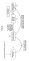
- FIG. 3 is an exemplary diagram illustrating screen transition of a conventional television broadcast receiver in the embodiment
- FIG. 4 is an exemplary diagram illustrating a list screen for selecting a connection destination television broadcast receiver on a personal computer (PC) in the embodiment;
- FIG. 5 is an exemplary diagram illustrating screen transition of the television broadcast receiver in the embodiment
- FIG. 6 is an exemplary diagram illustrating a connection waiting screen of the television broadcast receiver in the embodiment.
- FIG. 7 is an exemplary diagram illustrating a PIN-code display screen of the television broadcast receiver in the embodiment.
- FIG. 8 is an exemplary diagram illustrating state transition of the television broadcast receiver in the embodiment.
- FIG. 9 is an exemplary flowchart of a first connection process performed by the television broadcast receiver to realize a remote display in the embodiment.
- FIG. 10 is an exemplary flowchart of a second or subsequent connection process performed by the television broadcast receiver to realize a remote display in the embodiment.
- a television apparatus comprises a receiving module, a display controller, a receiving controller, an obtaining module, a storage module, and a controller.
- the receiving module is configured to receive an operation for putting the television apparatus into a waiting state to connect to an external device.
- the display controller is configured to display identification information identifying the television apparatus when the television apparatus is put into the waiting state upon receipt of the operation by the receiving module, display security information generated randomly if a request for connection to the television apparatus identified by the identification information is received from the external device, and display screen information received from the external device if the security information is received from the external device.
- the receiving controller is configured to receive the request for connection and the security information from the external device.
- the obtaining module is configured to obtain external-device identification information identifying the external device if communication with the external device is initiated upon receipt of the security information.
- the storage module is configured to store the external-device identification information.
- the controller is configured to control the display controller to display the screen information received from the external device without putting the television apparatus into the waiting state if a request for communication is received from the external device identified by the external-device identification information stored in the storage module.
- a display control device comprises a receiving module, a display controller, a receiving controller, an obtaining module, a storage module, and a controller.
- the receiving module is configured to receive an operation for putting the display control device into a waiting state to connect to an external device.
- the display controller is configured to display identification information identifying the display control device on a display module connected to the display control device when the display control device is put into the waiting state upon receipt of the operation by the receiving module, display security information generated randomly on the display module if a request for connection to the display control device identified by the identification information is received from the external device, and display screen information received from the external device on the display module if the security information is received from the external device.
- the receiving controller is configured to receive the request for connection and the security information from the external device.
- the obtaining module is configured to obtain external-device identification information identifying the external device if communication with the external device is initiated upon receipt of the security information.
- the storage module is configured to store the external-device identification information.
- the controller is configured to control the display controller to display the screen information received from the external device without putting the display control device into the waiting state if a request for communication from the external device identified by the external-device identification information stored in the storage module is received.
- a display control method applied to a television apparatus comprises: receiving an operation for putting the television apparatus into a waiting state to connect to an external device by a receiving module; displaying identification information identifying the television apparatus by a display controller when the television apparatus is put into the waiting state upon receipt of the operation at the receiving; receiving a request for connection to the television apparatus identified by the identification information from the external device by the receiving module; displaying security information generated randomly upon receipt of the request for connection by the display controller; receiving the security information from the external device by the receiving module; obtaining external-device identification information identifying the external device by an obtaining module if communication with the external device is initiated upon receipt of the security information; storing the external-device identification information in a storage module; displaying screen information received from the external device by the display controller upon receipt of the security information; and controlling the display controller to display the screen information received from the external device without putting the television apparatus into the waiting state by a controller if a request for communication is received from the external device identified by the external-device identification information stored in
- FIG. 1 is a diagram illustrating an overall framework according to an embodiment. As illustrated in FIG. 1 , it is assumed, for example, that example where a television broadcast receiver 100 , a remote controller 110 for operating the television broadcast receiver 100 , and a personal computer (PC) 150 are present in a house. Although only one television broadcast receiver is illustrated in FIG. 1 , there is a plurality of television broadcast receivers which can be connected to the PC 150 .
- PC personal computer
- the television broadcast receiver 100 which receives a broadcast from a broadcasting station 180 and displays the broadcast, has a function capable of displaying a display screen received from the PC 150 connected to the television broadcast receiver 100 via wireless communication. By using the function, the television broadcast receiver 100 can be switched from a state of playing a TV program to a display of the screen of the PC 150 in accordance with operations with respect to the PC 150 and the television broadcast receiver 100 . In the display switching, a personal identification number (PIN) code displayed on the screen of the television broadcast receiver 100 has to be input to the PC 150 .
- PIN personal identification number
- a PIN code is a combination of numbers which is randomly generated each time the television broadcast receiver 100 displays it, and is a security code required for connection to the television broadcast receiver 100 .
- a user inputs a PIN code displayed on the television broadcast receiver 100 to the PC 150 , and the PC 150 transmits the input PIN code to the television broadcast receiver 100 , thereby establishing mutual communication for a remote display.
- FIG. 2 is a diagram illustrating a hardware configuration of the television broadcast receiver 100 .
- FIG. 2 is a block diagram illustrating main signal processing systems of the television broadcast receiver 100 described above.
- a broadcast receiving antenna 201 is connected to the input side of the television broadcast receiver 100 .
- the television broadcast receiver 100 can directly operate an external display device or audio output device, and the user can operate the television broadcast receiver 100 via an operation module (not illustrated) provided on the television broadcast receiver 100 or via the remote controller 110 with infrared communication.
- the television broadcast receiver 100 decodes a received digital television broadcast signal, thereby displaying a broadcast program, and the user can watch the received broadcast program.
- the broadcast program can be watched with the external display device and audio output device, and the received broadcast program can be recorded.
- the television broadcast receiver 100 illustrated in FIG. 2 may comprise a plurality of receiving circuits, such as tuners, for receiving broadcast waves.
- a terrestrial digital television broadcast signal received by the terrestrial-broadcast receiving antenna 201 is supplied to a terrestrial digital broadcasting tuner 203 via an input terminal 202 .
- the tuner 203 selects a broadcast signal of a desired channel in accordance with a control signal from a processing module 205 , and outputs the selected broadcast signal to a demodulator 204 a.
- the demodulator 204 a demodulates the broadcast signal selected by the tuner 203 in accordance with a control signal from the processing module 205 , and obtains a transport stream including the desired program, and then outputs the obtained transport stream to a decoder 204 b.
- the decoder 204 b performs a transport stream (TS) decoding on a TS multiplexed signal in accordance with a control signal from the processing module 205 , and outputs a packetized elementary stream (PES) obtained by depacketizing digital video and audio signals of the desired program to an STD buffer in a signal processing module 206 .
- the decoder 204 b outputs section information sent through a digital broadcast to a section module 232 in the signal processing module 206 .
- the signal processing module 206 comprises a decoder 231 and the section module 232 , and performs processing of an input signal.
- the decoder 231 selectively performs predetermined digital signal processing with respect to the digital video and audio signals supplied from the decoder 204 b , and outputs the processed signals to a graphics processing module 207 and an audio processing module 208 .
- the decoder 231 selectively performs predetermined digital signal processing with respect to the digital video and audio signals supplied from the decoder 204 b , and records the processed signals on a recording device 270 such as a hard disk drive (HDD) via the processing module 205 .
- a recording device 270 such as a hard disk drive (HDD)
- the decoder 231 performs predetermined digital signal processing with respect to data of the recorded program read from the recording device 270 (for example, HDD) via the processing module 205 , and outputs the processed data to the graphics processing module 207 and the audio processing module 208 .
- the decoder 231 performs predetermined digital signal processing with respect to data received from the PC 150 via the processing module 205 , and outputs the processed data to the graphics processing module 207 and the audio processing module 208 .
- various data for obtaining a program (such as key information for B-CAS descrambling), electronic program guide (EPG) information, program attribute information (such as a category of the program), and caption information (service information (SI) and program specific information (PSI)), etc. are input from the signal processing module 206 .
- the processing module 205 performs an image generating process to display an EPG and a caption from the input information, and outputs the generated image information to the graphics processing module 207 .
- the processing module 205 has a function of controlling program recording and program timer recording. Upon receipt of timer recording, the processing module 205 displays EPG information on a display device 211 , and sets content of the timer recording input by the user via an operation module 220 or the remote controller 110 in a predetermined storage module. Then, the processing module 205 controls the tuner 203 , the demodulator 204 a , the decoder 204 b , and the signal processing module 206 to record the program at the set time.
- the section module 232 outputs various data for obtaining a program, EPG information, program attribute information (such as a category of the program), and caption information (SI and PSI), etc. out of the section information input from the decoder 204 b to the processing module 205 .
- the graphics processing module 207 has a function of synthesizing (1) a digital video signal supplied from the decoder 231 in the signal processing module 206 , (2) an on screen display (OSD) signal generated by an OSD-signal generating module 209 , (3) image data of a data broadcast, and (4) an EPG and a caption signal which are generated by the processing module 205 and outputting the synthesized data to a video processing module 210 .
- OSD on screen display
- EPG EPG and a caption signal which are generated by the processing module 205 and outputting the synthesized data to a video processing module 210 .
- the graphics processing module 207 superimposes caption information on the video signal based on the caption information under the control of the processing module 205 .
- a digital video signal output from the graphics processing module 207 is supplied to the video processing module 210 .
- the video processing module 210 converts the input digital video signal into an analog video signal which can be displayed on the display device 211 , and outputs the analog video signal to the display device 211 to display the video on the display device 211 .
- the video processing module 210 can output a video signal in a format which can be displayed on an external display device (not illustrated) to the external display device via an output terminal 212 to display the video on the external display device.
- the audio processing module 208 converts an input digital audio signal into an analog audio signal which can be played by an audio output device 213 , and outputs the analog audio signal to the audio output device 213 to cause the audio output device 213 to play the audio.
- the audio processing module 208 can output an audio signal in a format which can be played by an external audio output device (not illustrated) to the external audio output device via an output terminal 214 to cause the external audio output device to play the audio.
- the processing module 205 comprises a central processing unit (CPU) and the like, and receives operation information from the operation module 220 or receives operation information sent from the remote controller 110 via a light receiving module 221 , and controls the modules to reflect content of an operation (such as a channel switching operation).
- CPU central processing unit
- the processing module 205 mainly uses a read only memory (ROM) 205 a in which a control program executed by the CPU is stored, a random access memory (RAM) 205 b used to provide a working area to the CPU, and a nonvolatile memory 205 c , such as a flash memory, in which various setting information, control information, and program information, etc. are stored.
- ROM read only memory
- RAM random access memory
- nonvolatile memory 205 c such as a flash memory
- the processing module 205 is connected to a wireless local area network (LAN) terminal 223 via a Wi-Fi communication I/F 222 . This enables the processing module 205 to transmit information to a LAN-enabled device (for example, the PC 150 ) connected to the wireless LAN terminal 223 via a wireless communication line through the Wi-Fi communication I/F 222 .
- a LAN-enabled device for example, the PC 150
- the processing module 205 further comprises a remote display module 250 .
- the remote display module 250 comprises a receiving module 251 , a controller 252 , a display controller 253 , an obtaining module 254 , and a receiving controller 255 .
- FIG. 3 is a diagram illustrating screen transition of a conventional television broadcast receiver from when the television broadcast receiver is remotely connected to a PC till when the television broadcast receiver achieves a remote display function.
- the connection process can be completed without operating the television broadcast receiver.
- a remote display application for realizing a remote display on the television broadcast receiver is activated on the PC side.
- the remote display application When the remote display application is activated, the remote display application scans a television broadcast receiver having a remote display function via wireless communication. Then, the remote display application displays a list of IDs identifying television broadcast receivers having the remote display function. Then, the remote display application receives selection of a television broadcast receiver to which screen information is to be transferred as a remote display from a user, and after that, the remote display application establishes communication for remote connection with the selected television broadcast receiver.
- the display screen of the selected television broadcast receiver is switched from a broadcast screen 301 airing a broadcast to a connection start screen 302 . If it is the first time the television broadcast receiver is connected to the PC, the display screen of the television broadcast receiver is further switched to a PIN-code display screen 303 .
- a PIN code displayed on the PIN-code display screen 303 is a Wi-Fi protected setup (WPS) PIN code, and is a combination of numbers which is randomly generated in the television broadcast receiver.
- WPS Wi-Fi protected setup
- the remote display application on the PC side When the remote display application on the PC side receives an input operation of the PIN code from the user, the remote display application issues a request for connection using the PIN code to the television broadcast receiver.
- the television broadcast receiver displays the same screen 304 as that is displayed on the PC as a remote display of the PC.
- the television broadcast receiver stores information on the remote connection to the PC connected by wireless in the nonvolatile memory thereof. This allows the user to connect the PC to the television broadcast receiver without inputting the PIN code from the next time.
- the television broadcast receiver makes the screen transition from the connection start screen 302 to the same screen 304 as that is displayed on the PC without the screen transition from the connection start screen 302 to the PIN-code display screen 303 .
- a user has to confirm an ID identifying a connection destination television broadcast receiver in advance. If the user performs a connection operation without confirmation of the ID in advance, in a case where there is a plurality of devices accommodating a remote display, the user is more likely to select a wrong device from a list of the devices.
- the PC recognizes a plurality of connectable television broadcast receivers. At this time, if the user selects a wrong television broadcast receiver, the television broadcast receiver in someone's house makes the screen transition to a screen for connecting to the PC (for example, the PIN-code display screen).
- the conventional television broadcast receiver illustrated in FIG. 3 automatically makes the transition from the display screen on which a TV program is currently aired to the PIN-code display screen. Therefore, if the user selects a device in a someone's house by mistake, television watching in the house may be obstructed.
- a television broadcast receiver may be configured to make the transition to a screen for connecting to the PC 150 only if a predetermined operation is performed on the television broadcast receiver and the television broadcast receiver is put into a waiting state.
- the predetermined operation is required to connect to the PC 150 each time (even if it is not the first time).
- the predetermined operation is required to put the television broadcast receiver into the waiting state with each connection, so the user's operational load is increased and the user-friendliness is reduced.
- the PC 150 of the present embodiment stores therein the remote display application.
- the remote display application When the remote display application is activated, the user can select a connectable television broadcast receiver through the remote display application running on the PC 150 .
- FIG. 4 is a diagram illustrating an example of a list screen for selecting a connection destination television broadcast receiver from a list of connectable television broadcast receivers through the remote display application running on the PC 150 .
- a list of respective IDs, manufacturer names, and model numbers of the connectable television broadcast receivers is displayed.
- An ID of a television broadcast receiver here is for identifying the television broadcast receiver, and is displayed when the television broadcast receiver is put into the connection waiting state. Namely, the user visually confirms an ID displayed when a television broadcast receiver is put into the connection waiting state, and after that, the user selects the ID from a list of IDs displayed on the PC 150 , so that the desired television broadcast receiver can be selected as a connection destination.
- the receiving module 251 receives a waiting request operation for putting the television broadcast receiver 100 into the waiting state to connect to the PC 150 .
- the waiting request operation is, for example, to press a predetermined button of the remote controller 110 or to press a button provided on the television broadcast receiver 100 .
- the controller 252 performs various control processes to realize a remote display. For example, when the receiving module 251 receives a waiting request operation, the controller 252 controls the television broadcast receiver 100 to be put into the connection waiting state.
- the display controller 253 displays various information on the display device 211 of the television broadcast receiver 100 to realize a remote display. For example, when the receiving module 251 receives a waiting request operation and the controller 252 puts the television broadcast receiver 100 into the connection waiting state, the display controller 253 displays an ID identifying the television broadcast receiver 100 on the display device 211 . The user visually confirms the displayed ID, so the user can select the ID as a connect destination through the remote display application running on the PC 150 .
- FIG. 5 is a diagram illustrating screen transition of the television broadcast receiver 100 according to the present embodiment. As illustrated in FIG. 5 , when the receiving module 251 receives a new connection operation while the television broadcast receiver 100 displays a broadcast screen 501 airing a broadcast, the television broadcast receiver 100 is put into the connection waiting state, and the display controller 253 switches the display screen of the television broadcast receiver 100 to a connection waiting screen 502 .
- FIG. 6 is a diagram illustrating an example of the connection waiting screen 502 .
- a manufacturer name and a model number of the television broadcast receiver 100 are displayed. This can prevent the user from selecting a wrong ID.
- the controller 252 controls the television broadcast receiver 100 to be released from the connection waiting state.
- the predetermined time is set to an appropriate time in each embodiment in consideration for user's convenience.
- the display controller 253 switches the display screen of the television broadcast receiver 100 from the connection waiting screen 502 to the broadcast screen 501 .
- the receiving controller 255 receives various information from the PC 150 to realize a remote display. For example, the receiving controller 255 receives a connection request with respect to the television broadcast receiver 100 identified by the displayed ID from the PC 150 .
- the display controller 253 displays a connection start screen 503 in FIG. 5 .
- the display controller 253 next displays a PIN-code display screen 504 .
- a PIN code is a security code which is randomly generated to maintain the security in connection to the television broadcast receiver 100 .
- FIG. 7 is a diagram illustrating an example of the PIN-code display screen 504 . As illustrated in FIG. 7 , on the PIN-code display screen 504 , a PIN code required for connection to the television broadcast receiver 100 is displayed.
- the user inputs the PIN code to the remote display application running on the PC 150 .
- the PC 150 transmits the PIN code to the television broadcast receiver 100 .
- the receiving controller 255 receives the PIN code from the PC 150 .
- the receiving controller 255 has received the PIN code, communication between the PC 150 and the television broadcast receiver 100 for realizing a remote display is established, and the display controller 253 displays the same screen 505 as that is displayed on the PC 150 on the display device 211 in accordance with data transmitted from the PC 150 .
- the obtaining module 254 obtains identification information identifying the PC 150 from the PC 150 . Then, the obtaining module 254 stores the obtained identification information in the nonvolatile memory 205 c .
- the identification information identifying the PC 150 can be any information as long as the information can identify the PC 150 .
- the identification information includes a media access control (MAC) address.
- the controller 252 establishes communication between the PC 150 and the television broadcast receiver 100 even if the television broadcast receiver 100 is not put into the connection waiting state. After that, the controller 252 controls the display controller 253 to display screen information received from the PC 150 on the display device 211 .
- the controller 252 puts the television broadcast receiver 100 into the connection waiting state to register the new PC in accordance with an operation made on the remote controller 110 .
- the controller 252 controls the television broadcast receiver 100 not to make the screen transition due to a connection request from a new PC.
- the controller 252 causes the connection waiting state in which a new PC can be registered to time out after the elapse of a certain period of time, and puts the television broadcast receiver 100 into a state in which a new PC cannot be registered (for example, a state in which a usual broadcast screen is displayed). Subsequently, such state transition is explained in detail.
- FIG. 8 is a diagram illustrating state transition of the television broadcast receiver 100 according to the present embodiment.
- a state in which the display controller 253 displays a usual broadcast screen as a connection start waiting state is referred to as a state 801 .
- the television broadcast receiver 100 makes the transition to the state 801 in which a usual broadcast screen is displayed.
- the television broadcast receiver 100 issues a connection request to the television broadcast receiver 100 .
- the television broadcast receiver 100 confirms whether the television broadcast receiver 100 has ever been connected to the PC, a connection requestor, based on identification information stored in the nonvolatile memory 205 c (a state 806 ).
- the controller 252 maintains the television broadcast receiver 100 in the state 801 in which the usual broadcast screen is displayed.
- the television broadcast receiver 100 starts communicating with the known PC, and makes the transition to a state 807 in which the display controller 253 displays “start of connection”. Then, after the communication with the PC has been established, the display controller 253 puts the television broadcast receiver 100 into a state 808 in which the same screen as that is displayed on the known PC is displayed.
- the controller 252 puts the television broadcast receiver 100 into a connection waiting state 802 for waiting for the start of connection to the new PC, and the display controller 253 displays information that the television broadcast receiver 100 is in the connection waiting state and an ID for identifying the television broadcast receiver 100 as illustrated in FIG. 6 .
- the PC transmits a connection request to the television broadcast receiver 100 .
- the television broadcast receiver 100 When receiving the connection request from the PC via the Wi-Fi communication I/F 222 , the television broadcast receiver 100 starts connecting to the PC, and the display controller 253 displays information that the connection has been started (a state 803 ). After that, the controller 252 confirms whether the PC which has issued the connection request is a PC to which the television broadcast receiver 100 has ever been connected based on the identification information stored in the nonvolatile memory 205 c (a state 804 ). When it is determined that the television broadcast receiver 100 has been connected to the PC before, after communication with the PC has been established, the television broadcast receiver 100 is put into a state 808 in which the display controller 253 displays the same screen as that is displayed on the known PC.
- the television broadcast receiver 100 is put into a state 805 in which the display controller 253 displays the PIN-code display screen. Then, when an input operation of a PIN code is made on the PC, the PC transmits the PIN code to the television broadcast receiver 100 .
- the controller 252 puts the television broadcast receiver 100 into the state 808 in which the display controller 253 displays the same screen as that is displayed on the unknown PC.
- FIG. 9 is a flowchart of the operation of the television broadcast receiver 100 according to the present embodiment.
- the display controller 253 controls to display a current broadcast program on the television broadcast receiver 100 as a broadcast screen (S 901 ).
- the controller 252 puts the television broadcast receiver 100 into the connection waiting state (S 903 ).
- the display controller 253 controls to display an ID identifying the television broadcast receiver 100 on a connection waiting screen (S 904 ).
- the controller 252 determines whether a predetermined time has passed (S 906 ). When it is determined that the predetermined time has not passed (NO at S 906 ), returning to S 904 , the display controller 253 continuously controls to display the ID. On the other hand, when it is determined that the predetermined time has passed (YES at S 906 ), the controller 252 releases the television broadcast receiver 100 from the connection waiting state (S 907 ), and the display controller 253 controls to display the current broadcast program again (S 901 ).
- the display controller 253 displays information that the connection is started (S 908 ).
- the controller 252 determines whether identification information of the PC 150 requesting for the start of connection has already been stored in the nonvolatile memory 205 c (S 909 ).
- the display controller 253 controls to display the same screen as the display screen of the PC 150 (S 913 ).
- the display controller 253 controls to display a PIN code on the screen (S 910 ). Then, whether the receiving controller 255 has received the PIN code from the PC 150 is determined (S 911 ). When the receiving controller 255 has not received the PIN code (NO at S 911 ), the display controller 253 continuously controls to display the PIN code (S 910 ).
- the controller 252 stores information identifying the PC 150 which has transmitted the PIN code in the nonvolatile memory 205 c (S 912 ).
- the display controller 253 controls to display the same screen as the display screen of the PC 150 (S 913 ).
- the television broadcast receiver 100 when connecting to the PC 150 for the first time, the television broadcast receiver 100 has to be put into the connection waiting state. Therefore, it is possible to avoid switching the screen of an unintended television broadcast receiver.
- FIG. 10 is a flowchart of the operation of the television broadcast receiver 100 of the embodiment.
- the display controller 253 controls to display a current broadcast program on the television broadcast receiver 100 as a broadcast screen (S 1001 ).
- the controller 252 determines whether identification information of the PC 150 requesting for the start of connection has already been stored in the nonvolatile memory 205 c (S 1003 ). When it is determined that identification information of the PC 150 has not been stored in the nonvolatile memory 205 c (NO at S 1003 ), returning to S 1001 , the display controller 253 continuously controls to display the current broadcast program.
- the display controller 253 controls to display the same screen as the display screen of the PC 150 (S 1004 ).
- the television broadcast receiver 100 when connecting to the PC 150 for the second or subsequent time, the television broadcast receiver 100 does not have to be put into the connection waiting state; therefore, it is possible to reduce the user's operational load.
- the television broadcast receiver 100 When having not received an operation for putting the television broadcast receiver 100 into the connection waiting state through the remote controller 110 , the television broadcast receiver 100 does not receive a request for the start of connection for a remote display from a new PC. If the television broadcast receiver 100 receives the request, the request is treated as an error. The television broadcast receiver 100 can store information on the error in the nonvolatile memory 205 c.
- the television broadcast receiver 100 if there is no request for connection from a PC in a certain period of time since the television broadcast receiver 100 has been put into the connection waiting state upon receipt of an operation for putting the television broadcast receiver 100 into the connection waiting state through the remote controller 110 , as time-out processing, the television broadcast receiver 100 makes the transition to the original state (for example, a display screen of a current broadcast program). By such time-out transition, the possibility of unintended screen transition due to a wrong connection request can be reduced.
- the original state for example, a display screen of a current broadcast program
- an external device connected to the television broadcast receiver 100 is the PC 150 .
- the external device is not limited to the PC 150 ; for example, the external device can be a mobile device, such as a cellular phone unit.
- the television broadcast receiver 100 realizes a remote display.
- a device realizing the remote display is not limited to a television broadcast receiver, and the device may be a set-top box connected to a display.
- an example of a set-top box is explained.
- the set-top box according to the modification has basically the same configuration as the television broadcast receiver 100 in the embodiment except the display device 211 in the example illustrated in FIG. 2 .
- the set-top box further comprises an interface for connecting the set-top box to a display.
- the interface includes, for example, a high-definition multimedia interface (HDMI).
- HDMI high-definition multimedia interface
- the set-top box is connected to an external display via the interface, and controls to display such as a screen of a terrestrial digital broadcasting program on the display.
- the set-top box can transmit and receive information to/from a PC connected to the set-top box via a wireless communication line.
- the set-top box can receive a connection request from the PC, and can control to display the same screen as the PC on the display.
- the control up to the display control is identical to that is in the embodiment, and the description of the control is omitted.
- any other display control devices may realize a remote display as long as the display control device is connected to a display device, such as a display, via an external interface.
- the device in connection to a new PC, only if a device receives an operation for putting the device into a connection waiting state through an operation module, such as the remote controller 110 , in advance, the device receives a connection request from the new PC. Therefore, even if a wrong device is selected as a connection destination, it is possible to prevent screen transition of the wrong device. Furthermore, in second or subsequent connection to the PC, the operation for putting the device into the connection waiting state is not required; therefore, it is possible to reduce the operational load. Namely, according to the embodiment and the modification, it is possible to achieve simultaneous pursuit of ensuring of the security by prevention of screen transition of a wrong device and reduction of the operational load.
- the various modules of the systems described herein can be implemented as software applications, hardware and/or software modules, or components on one or more computers, such as servers. While the various modules are illustrated separately, they may share some or all of the same underlying logic or code.
Landscapes
- Engineering & Computer Science (AREA)
- Signal Processing (AREA)
- Multimedia (AREA)
- Automation & Control Theory (AREA)
- Computer Networks & Wireless Communication (AREA)
- Human Computer Interaction (AREA)
- Computer Security & Cryptography (AREA)
- Two-Way Televisions, Distribution Of Moving Picture Or The Like (AREA)
Abstract
Description
Claims (7)
Applications Claiming Priority (2)
| Application Number | Priority Date | Filing Date | Title |
|---|---|---|---|
| JP2010-236514 | 2010-10-21 | ||
| JP2010236514 | 2010-10-21 |
Publications (2)
| Publication Number | Publication Date |
|---|---|
| US20120099025A1 US20120099025A1 (en) | 2012-04-26 |
| US8495706B2 true US8495706B2 (en) | 2013-07-23 |
Family
ID=44508704
Family Applications (1)
| Application Number | Title | Priority Date | Filing Date |
|---|---|---|---|
| US13/111,046 Active US8495706B2 (en) | 2010-10-21 | 2011-05-19 | Television apparatus, display control device, and display control method |
Country Status (2)
| Country | Link |
|---|---|
| US (1) | US8495706B2 (en) |
| EP (1) | EP2445139A3 (en) |
Cited By (2)
| Publication number | Priority date | Publication date | Assignee | Title |
|---|---|---|---|---|
| US8997175B2 (en) * | 2010-07-21 | 2015-03-31 | Lenovo Innovations Limited (Hong Kong) | Wireless LAN communication terminal and communication control method thereof in wireless LAN system for the same |
| US20160277932A1 (en) * | 2013-03-15 | 2016-09-22 | Canon Kabushiki Kaisha | Communication apparatus, method of controlling the same, program, and printing apparatus |
Families Citing this family (6)
| Publication number | Priority date | Publication date | Assignee | Title |
|---|---|---|---|---|
| US8576773B2 (en) * | 2009-06-30 | 2013-11-05 | Intel Corporation | Wireless access point with digital television capabilities |
| KR20120139475A (en) * | 2011-06-17 | 2012-12-27 | 삼성전자주식회사 | Display apparatus for setting a remote controller device and displaying method thereof |
| JP2014112766A (en) * | 2012-12-05 | 2014-06-19 | Toshiba Corp | Electronic apparatus, control method, and control program |
| JP2014225766A (en) * | 2013-05-16 | 2014-12-04 | ソニー株式会社 | Information processor, information processing method and program |
| JP5901589B2 (en) * | 2013-08-29 | 2016-04-13 | 京セラドキュメントソリューションズ株式会社 | Image forming system |
| EP3144798B1 (en) * | 2015-09-18 | 2020-12-16 | Canon Kabushiki Kaisha | Image processing apparatus, method of controlling the same, and storage medium |
Citations (19)
| Publication number | Priority date | Publication date | Assignee | Title |
|---|---|---|---|---|
| US5396546A (en) * | 1991-10-03 | 1995-03-07 | Viscorp | Apparatus and method for automatic and user configurable information appliance |
| JP2000123210A (en) | 1998-10-13 | 2000-04-28 | Matsushita Electric Ind Co Ltd | On-vehicle equipment for pay road charge collecting facility |
| WO2004079962A2 (en) | 2003-03-07 | 2004-09-16 | Nokia Corporation | Method and device for identifying and pairing bluetooth devices |
| US6795130B2 (en) * | 2000-08-04 | 2004-09-21 | Canon Kabushiki Kaisha | Signal receiving apparatus, remote controller, signal receiving system, and apparatus to be controlled |
| US20060140175A1 (en) | 2004-12-28 | 2006-06-29 | Yong-Hee Han | System and method for controlling coupling between communication terminals for audio-video communication |
| US20080016537A1 (en) | 2006-07-17 | 2008-01-17 | Research In Motion Limited | Management of multiple connections to a security token access device |
| US20080039063A1 (en) | 2006-05-19 | 2008-02-14 | Seiko Epson Corporation | Image display system, image display device of image display system, mobile terminal device, connection establishment method of image display system |
| JP2008152625A (en) | 2006-12-19 | 2008-07-03 | Necディスプレイソリューションズ株式会社 | Image display device, image data processing system and image data processing method |
| US20080160914A1 (en) | 2006-12-29 | 2008-07-03 | Mcrae Matthew B | Secure pairing of networked devices |
| JP2008219457A (en) | 2007-03-05 | 2008-09-18 | Seiko Epson Corp | Wireless communication setting device, wireless communication setting method, and program |
| JP2009016952A (en) | 2007-06-29 | 2009-01-22 | Toshiba Corp | Electronic equipment and communication system |
| JP2009212732A (en) | 2008-03-03 | 2009-09-17 | Sony Corp | Communication device and communication method |
| JP2009217370A (en) | 2008-03-07 | 2009-09-24 | Nippon Hoso Kyokai <Nhk> | Content viewing terminal, its program, and content viewing right transfer method |
| JP2010021802A (en) | 2008-07-10 | 2010-01-28 | Toshiba Corp | Wireless communication device |
| JP2010041508A (en) | 2008-08-06 | 2010-02-18 | Nikon Corp | Wireless communication apparatus |
| US20100082725A1 (en) | 2008-09-26 | 2010-04-01 | Fujitsu Limited | Control terminal for giving content reproduction command, content relay device and remote content reproduction system |
| JP2010098542A (en) | 2008-10-16 | 2010-04-30 | Sony Corp | Information processing apparatus, display device, and information processing system |
| JP2010114798A (en) | 2008-11-10 | 2010-05-20 | Mitsubishi Electric Corp | Wireless transmission system |
| US7756916B2 (en) * | 2005-06-10 | 2010-07-13 | Canon Kabushiki Kaisha | Display method |
-
2011
- 2011-05-19 US US13/111,046 patent/US8495706B2/en active Active
- 2011-05-31 EP EP11168322A patent/EP2445139A3/en not_active Withdrawn
Patent Citations (25)
| Publication number | Priority date | Publication date | Assignee | Title |
|---|---|---|---|---|
| US5396546A (en) * | 1991-10-03 | 1995-03-07 | Viscorp | Apparatus and method for automatic and user configurable information appliance |
| JP2000123210A (en) | 1998-10-13 | 2000-04-28 | Matsushita Electric Ind Co Ltd | On-vehicle equipment for pay road charge collecting facility |
| US6834267B1 (en) | 1998-10-13 | 2004-12-21 | Matsushita Electric Industrial Co., Ltd. | Vehicle-mounted toll-paying device that enables a safe verification of an inserted IC card |
| US6795130B2 (en) * | 2000-08-04 | 2004-09-21 | Canon Kabushiki Kaisha | Signal receiving apparatus, remote controller, signal receiving system, and apparatus to be controlled |
| WO2004079962A2 (en) | 2003-03-07 | 2004-09-16 | Nokia Corporation | Method and device for identifying and pairing bluetooth devices |
| US20060140175A1 (en) | 2004-12-28 | 2006-06-29 | Yong-Hee Han | System and method for controlling coupling between communication terminals for audio-video communication |
| US7756916B2 (en) * | 2005-06-10 | 2010-07-13 | Canon Kabushiki Kaisha | Display method |
| US20080039063A1 (en) | 2006-05-19 | 2008-02-14 | Seiko Epson Corporation | Image display system, image display device of image display system, mobile terminal device, connection establishment method of image display system |
| US20080016537A1 (en) | 2006-07-17 | 2008-01-17 | Research In Motion Limited | Management of multiple connections to a security token access device |
| JP2008152625A (en) | 2006-12-19 | 2008-07-03 | Necディスプレイソリューションズ株式会社 | Image display device, image data processing system and image data processing method |
| US20100115052A1 (en) | 2006-12-19 | 2010-05-06 | Eisaku Ishii | Apparatus for displaying an image, system processing image data, and method of processing image data |
| US20080160914A1 (en) | 2006-12-29 | 2008-07-03 | Mcrae Matthew B | Secure pairing of networked devices |
| JP2008219457A (en) | 2007-03-05 | 2008-09-18 | Seiko Epson Corp | Wireless communication setting device, wireless communication setting method, and program |
| JP2009016952A (en) | 2007-06-29 | 2009-01-22 | Toshiba Corp | Electronic equipment and communication system |
| US20100017612A1 (en) | 2007-06-29 | 2010-01-21 | Kabushiki Kaisha Toshiba | Electronic Apparatus and Communication System |
| JP2009212732A (en) | 2008-03-03 | 2009-09-17 | Sony Corp | Communication device and communication method |
| US8380982B2 (en) | 2008-03-03 | 2013-02-19 | Sony Corporation | Communication device and communication method |
| JP2009217370A (en) | 2008-03-07 | 2009-09-24 | Nippon Hoso Kyokai <Nhk> | Content viewing terminal, its program, and content viewing right transfer method |
| JP2010021802A (en) | 2008-07-10 | 2010-01-28 | Toshiba Corp | Wireless communication device |
| JP2010041508A (en) | 2008-08-06 | 2010-02-18 | Nikon Corp | Wireless communication apparatus |
| US20100082725A1 (en) | 2008-09-26 | 2010-04-01 | Fujitsu Limited | Control terminal for giving content reproduction command, content relay device and remote content reproduction system |
| JP2010081321A (en) | 2008-09-26 | 2010-04-08 | Fujitsu Ltd | Control terminal for giving content reproduction command, content relay device and remote content reproduction system |
| JP2010098542A (en) | 2008-10-16 | 2010-04-30 | Sony Corp | Information processing apparatus, display device, and information processing system |
| US20110179442A1 (en) | 2008-10-16 | 2011-07-21 | Kazuaki Toba | Information processing device, display device, and information processing system |
| JP2010114798A (en) | 2008-11-10 | 2010-05-20 | Mitsubishi Electric Corp | Wireless transmission system |
Non-Patent Citations (5)
| Title |
|---|
| European Patent Application No./Patent No. 11168322.3-2202/2445139, Extended European Search Report, mailed Aug. 22, 2012, (Applicant-Kabushiki Kaisha Toshiba, Reference No. 19094/EL). |
| European Patent Application No./Patent No. 11168322.3-2202/2445139, Extended European Search Report, mailed Aug. 22, 2012, (Applicant—Kabushiki Kaisha Toshiba, Reference No. 19094/EL). |
| Japanese Patent Application No. 2010-0082725, Notice of Rejection, mailed Aug. 23, 2011, (with English Translation). |
| Japanese Patent Application No. 2010-236514, Notice of Rejection, mailed Aug. 23, 2011, (with English Translation). |
| Japanese Patent Application No. 2011-264827, Notice of Rejection, mailed Mar. 5, 2013, (with English Translation). |
Cited By (6)
| Publication number | Priority date | Publication date | Assignee | Title |
|---|---|---|---|---|
| US8997175B2 (en) * | 2010-07-21 | 2015-03-31 | Lenovo Innovations Limited (Hong Kong) | Wireless LAN communication terminal and communication control method thereof in wireless LAN system for the same |
| US20160277932A1 (en) * | 2013-03-15 | 2016-09-22 | Canon Kabushiki Kaisha | Communication apparatus, method of controlling the same, program, and printing apparatus |
| US9628991B2 (en) * | 2013-03-15 | 2017-04-18 | Canon Kabushiki Kaisha | Communication apparatus, method of controlling the same, program, and printing apparatus |
| US20170180994A1 (en) * | 2013-03-15 | 2017-06-22 | Canon Kabushiki Kaisha | Communication apparatus, method of controlling the same, program, and printing apparatus |
| US10477399B2 (en) * | 2013-03-15 | 2019-11-12 | Canon Kabushiki Kaisha | Communication apparatus, method of controlling the same, program, and printing apparatus |
| US11019105B2 (en) * | 2013-03-15 | 2021-05-25 | Canon Kabushiki Kaisha | Communication apparatus, method of controlling the same, program, and printing apparatus |
Also Published As
| Publication number | Publication date |
|---|---|
| EP2445139A2 (en) | 2012-04-25 |
| EP2445139A3 (en) | 2012-09-19 |
| US20120099025A1 (en) | 2012-04-26 |
Similar Documents
| Publication | Publication Date | Title |
|---|---|---|
| US8495706B2 (en) | Television apparatus, display control device, and display control method | |
| US8903523B2 (en) | Audio processing device, audio processing method, and program | |
| KR101356490B1 (en) | Receiver and Method for processing a data communication between terminal and the reciver | |
| US20120026413A1 (en) | Remote Control Device Programming and Indication of Programming Mode Status | |
| US20120133833A1 (en) | Video Display Apparatus, Source Apparatus, Video Display Method, and Video Display System | |
| JP2014011734A (en) | Video processing device | |
| JP4996754B1 (en) | Display control apparatus and display control method | |
| WO2012144322A1 (en) | Video player device, video transmission device, video player program, video transmission program, and recording medium | |
| CN100596179C (en) | Method and apparatus for providing simplified peer-to-peer recording | |
| US20160127677A1 (en) | Electronic device method for controlling the same | |
| WO2014155621A1 (en) | Communication device, communication method, and program | |
| KR100617876B1 (en) | Multi Room Personal Video Storage | |
| US20130097648A1 (en) | Internet-enabled smart television | |
| US8515252B2 (en) | Recording/reproducing apparatus, video display apparatus, system and method for starting apparatus on network | |
| US8959257B2 (en) | Information processing apparatus and information processing method | |
| US20060061696A1 (en) | Signal reproduction apparatus and signal reproduction method | |
| US20060263044A1 (en) | Method of providing time shift function in audio/video network and apparatus for the same | |
| US8218952B2 (en) | Content playback device and content playback method | |
| JP2012109981A (en) | Display control device and display control method | |
| US9578368B2 (en) | Method and data processing apparatus supporting simultaneous playback | |
| JPWO2016006087A1 (en) | Control apparatus, method and program | |
| JP6271169B2 (en) | Program related programs | |
| WO2015037129A1 (en) | Electronic device and connection method for electronic device | |
| JP5622899B2 (en) | Display control apparatus and display control method | |
| JP4974840B2 (en) | Video display device and control method thereof |
Legal Events
| Date | Code | Title | Description |
|---|---|---|---|
| AS | Assignment |
Owner name: KABUSHIKI KAISHA TOSHIBA, JAPAN Free format text: ASSIGNMENT OF ASSIGNORS INTEREST;ASSIGNOR:KANDA, TOMOHIRO;REEL/FRAME:026306/0114 Effective date: 20110427 |
|
| STCF | Information on status: patent grant |
Free format text: PATENTED CASE |
|
| FEPP | Fee payment procedure |
Free format text: PAYOR NUMBER ASSIGNED (ORIGINAL EVENT CODE: ASPN); ENTITY STATUS OF PATENT OWNER: LARGE ENTITY |
|
| FPAY | Fee payment |
Year of fee payment: 4 |
|
| MAFP | Maintenance fee payment |
Free format text: PAYMENT OF MAINTENANCE FEE, 8TH YEAR, LARGE ENTITY (ORIGINAL EVENT CODE: M1552); ENTITY STATUS OF PATENT OWNER: LARGE ENTITY Year of fee payment: 8 |
|
| AS | Assignment |
Owner name: TOSHIBA TEC KABUSHIKI KAISHA, JAPAN Free format text: ASSIGNMENT OF ASSIGNORS INTEREST;ASSIGNOR:KABUSHIKI KAISHA TOSHIBA;REEL/FRAME:059669/0322 Effective date: 20220224 |
|
| MAFP | Maintenance fee payment |
Free format text: PAYMENT OF MAINTENANCE FEE, 12TH YEAR, LARGE ENTITY (ORIGINAL EVENT CODE: M1553); ENTITY STATUS OF PATENT OWNER: LARGE ENTITY Year of fee payment: 12 |