US8475526B2 - Apparatus and methods for loading of an IOL injector - Google Patents
Apparatus and methods for loading of an IOL injector Download PDFInfo
- Publication number
- US8475526B2 US8475526B2 US11/316,460 US31646005A US8475526B2 US 8475526 B2 US8475526 B2 US 8475526B2 US 31646005 A US31646005 A US 31646005A US 8475526 B2 US8475526 B2 US 8475526B2
- Authority
- US
- United States
- Prior art keywords
- iol
- injector
- loading chamber
- vial
- chamber component
- Prior art date
- Legal status (The legal status is an assumption and is not a legal conclusion. Google has not performed a legal analysis and makes no representation as to the accuracy of the status listed.)
- Expired - Fee Related, expires
Links
- 238000000034 method Methods 0.000 title claims abstract description 20
- 238000002347 injection Methods 0.000 claims description 2
- 239000007924 injection Substances 0.000 claims description 2
- 210000000695 crystalline len Anatomy 0.000 description 43
- 239000000463 material Substances 0.000 description 3
- 229920001296 polysiloxane Polymers 0.000 description 2
- 239000004697 Polyetherimide Substances 0.000 description 1
- 239000004743 Polypropylene Substances 0.000 description 1
- 210000002159 anterior chamber Anatomy 0.000 description 1
- 201000009310 astigmatism Diseases 0.000 description 1
- 230000006835 compression Effects 0.000 description 1
- 238000007906 compression Methods 0.000 description 1
- 210000004087 cornea Anatomy 0.000 description 1
- 230000000881 depressing effect Effects 0.000 description 1
- 230000035876 healing Effects 0.000 description 1
- 230000001771 impaired effect Effects 0.000 description 1
- 208000014674 injury Diseases 0.000 description 1
- 238000003780 insertion Methods 0.000 description 1
- 230000037431 insertion Effects 0.000 description 1
- 238000004519 manufacturing process Methods 0.000 description 1
- 238000012986 modification Methods 0.000 description 1
- 230000004048 modification Effects 0.000 description 1
- 229920001601 polyetherimide Polymers 0.000 description 1
- -1 polypropylene Polymers 0.000 description 1
- 229920001155 polypropylene Polymers 0.000 description 1
- 238000000926 separation method Methods 0.000 description 1
- 230000008733 trauma Effects 0.000 description 1
Images


Classifications
-
- A—HUMAN NECESSITIES
- A61—MEDICAL OR VETERINARY SCIENCE; HYGIENE
- A61F—FILTERS IMPLANTABLE INTO BLOOD VESSELS; PROSTHESES; DEVICES PROVIDING PATENCY TO, OR PREVENTING COLLAPSING OF, TUBULAR STRUCTURES OF THE BODY, e.g. STENTS; ORTHOPAEDIC, NURSING OR CONTRACEPTIVE DEVICES; FOMENTATION; TREATMENT OR PROTECTION OF EYES OR EARS; BANDAGES, DRESSINGS OR ABSORBENT PADS; FIRST-AID KITS
- A61F2/00—Filters implantable into blood vessels; Prostheses, i.e. artificial substitutes or replacements for parts of the body; Appliances for connecting them with the body; Devices providing patency to, or preventing collapsing of, tubular structures of the body, e.g. stents
- A61F2/02—Prostheses implantable into the body
- A61F2/14—Eye parts, e.g. lenses or corneal implants; Artificial eyes
- A61F2/16—Intraocular lenses
- A61F2/1662—Instruments for inserting intraocular lenses into the eye
- A61F2/1664—Instruments for inserting intraocular lenses into the eye for manual insertion during surgery, e.g. forceps-like instruments
-
- A—HUMAN NECESSITIES
- A61—MEDICAL OR VETERINARY SCIENCE; HYGIENE
- A61F—FILTERS IMPLANTABLE INTO BLOOD VESSELS; PROSTHESES; DEVICES PROVIDING PATENCY TO, OR PREVENTING COLLAPSING OF, TUBULAR STRUCTURES OF THE BODY, e.g. STENTS; ORTHOPAEDIC, NURSING OR CONTRACEPTIVE DEVICES; FOMENTATION; TREATMENT OR PROTECTION OF EYES OR EARS; BANDAGES, DRESSINGS OR ABSORBENT PADS; FIRST-AID KITS
- A61F2/00—Filters implantable into blood vessels; Prostheses, i.e. artificial substitutes or replacements for parts of the body; Appliances for connecting them with the body; Devices providing patency to, or preventing collapsing of, tubular structures of the body, e.g. stents
- A61F2/02—Prostheses implantable into the body
- A61F2/14—Eye parts, e.g. lenses or corneal implants; Artificial eyes
- A61F2/16—Intraocular lenses
- A61F2/1662—Instruments for inserting intraocular lenses into the eye
- A61F2/167—Instruments for inserting intraocular lenses into the eye with pushable plungers
Definitions
- the present invention relates to intraocular lens (IOL) injectors, and more particularly to loading apparatus and methods for IOL injectors.
- IOL intraocular lens
- IOLs are artificial lenses used to replace natural crystalline lenses of eyes when the natural lenses are diseased or otherwise impaired. Under some circumstances a natural lens may remain in an eye together with an implanted IOL. IOLs may be placed in either the posterior chamber or anterior chamber of an eye.
- IOLs come in a variety of configurations and materials.
- Various instruments and methods for implanting such IOLs in an eye are known.
- an incision is made in a patient's cornea and an IOL is inserted into the eye through the incision.
- a surgeon uses surgical forceps having opposing blades to grasp the IOL and insert it through the incision into the eye. While this technique is still practiced today, more and more surgeons are using IOL injectors which offer advantages such as affording a surgeon more control when inserting an IOL into an eye and permitting insertion of IOLs through smaller incisions.
- Smaller incision sizes e.g., less than about 3 mm
- larger incisions e.g., about 3.2 to 5+mm
- smaller incisions have been attributed to reduced post-surgical healing time and reduced complications such as induced astigmatism.
- IOLs In order for an IOL to fit through a smaller incision, it is typically folded and/or compressed prior to entering the eye where they will assume their original unfolded/uncompressed shape. Since IOLs are very small and delicate articles of manufacture, great care must be taken in their handling, both as they are loaded into an injector and as the lens is injected into a patient's eye.
- aspects of the present invention are directed to an IOL injector comprising a loading chamber comprising a component that when being closed folds the lens. Additional aspects of the present invention are directed to a vial for maintaining an IOL prior to loading.
- the vial includes an injector guide that receives an injector such that when the injector is rotated a folded IOL can be obtained in the injector.
- the injector and vial are provided in a combination. As defined here in “a combination” includes but is not limited to arrangements in which the objects in the combination are packaged and are not connected to one another.
- the injector having tapered edge and the vial having a flexible arm are provided in a combination.
- a first aspect of the invention is directed to an IOL injector, comprising an injector body having a loading chamber and defining a lumen extending along a longitudinal axis.
- An opening to the loading chamber being defined by a tapered edge, and the edge extends in the direction of the longitudinal axis.
- the tapered edge is aligned parallel to the longitudinal axis.
- the tapered edge may extend along the entire length of the opening. In some embodiments, the tapered edge is sharp.
- the opening to the loading chamber may be further defined by a non-tapered edge, the non-tapered edge extending in the direction of the longitudinal axis. In some embodiments, the opening to the loading chamber is further defined by a second edge, the second edge extending parallel to the direction of the longitudinal axis, and a cross section of the lumen perpendicular to the longitudinal axis at the loading chamber is substantially circular. In such embodiments, the radial distance from the center of the loading chamber to the tapered edge in the cross section may be greater than the radial distance from the center of the loading chamber to the second edge in the cross section.
- the injector further comprises a concave outer surface disposed substantially opposite the opening.
- the injector may be in a combination with a vial comprising a convex interior surface and a flexible arm adapted to maintain an IOL against a surface opposite the convex interior surface.
- the concave exterior surface and the convex interior surface have substantially the same radius of curvature.
- Another aspect of the invention is directed to an IOL vial comprising a convexly curved interior surface and a flexible arm adapted to maintain an IOL against a surface opposite the convexly curved surface.
- the vial may comprise a vial base wherein the flexible arm is hingedly attached to the vial base.
- Yet another aspect of the invention is directed to a method of loading an IOL injector comprising an injector body and a loading chamber with an IOL, the method comprising inserting the loading chamber into a vial that contains an IOL; and rotating the IOL injector body relative to at least a portion of the vial to obtain the IOL in the loading chamber.
- the IOL injector has a lumen with a longitudinal axis and the step of rotating comprises rotation about an axis parallel to the longitudinal axis.
- the step of rotating the IOL injector body may cause rotation of a first loading chamber component relative to a second loading chamber component.
- the step of rotating the IOL injector body comprises folding the IOL to obtain the IOL in a folded configuration in the loading chamber.
- the IOL is ready for injection after the step of rotating.
- the IOL injector has a lumen, and upon rotation, a first loading chamber component and a second loading chamber component combine to form a portion of the lumen.
- the portion of the lumen may be a rotationally complete portion of the lumen.
- the first loading chamber component and the second loading chamber component become attached to one another after rotation.
- the step of inserting may comprise inserting the injector along a guide. The step of inserting may result in detaching the lens from a lens holder.
- injector contact surface is defined herein as a surface arranged to contact an IOL lens after the loading chamber is closed.
- An injector having an IOL that is “ready for delivery” is an injector that is in a condition such that actuation of its IOL ejection apparatus (e.g., a plunger) results in ejection of the IOL from the injector.
- FIG. 1A is a perspective view of an exemplary embodiment of an injector according to aspects of the present invention having an open loading chamber;
- FIG. 1B is a perspective view of an exemplary embodiment of a injector according to aspects of the present invention having a closed loading chamber;
- FIG. 1C is a perspective view of an exemplary embodiment of a injector according to aspects of the present invention having a tip attached;
- FIG. 2A is a perspective view of an exemplary embodiment of a vial according to aspects of the present invention.
- FIGS. 2B-C are side views of the exemplary embodiment of the vial illustrated in FIG. 2A ;
- FIG. 3A is a plan view of an exemplary embodiment of a lens holder according to aspects of the present invention.
- FIG. 3B is a side view of the exemplary embodiment of the lens holder illustrated in FIG. 3A ;
- FIG. 4 is a perspective view of the exemplary embodiment of an injector as illustrated in FIG. 1A engaged with the exemplary embodiment of a vial as illustrated in FIG. 2A , in which a portion of the vial is broken away;
- FIGS. 5A-5C illustrate steps for loading an injector according to aspects of the present invention
- FIG. 6A is a perspective view of a second exemplary embodiment of an injector according to aspects of the present invention having an open loading chamber;
- FIG. 6B is a perspective view of the second exemplary embodiment of the injector according to aspects of the present invention having a closed loading chamber
- FIG. 6C is a side view of the second exemplary embodiment illustrating a loading chamber opening
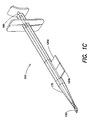
- FIG. 7 is a perspective view of the second exemplary embodiment of an injector as illustrated in FIG. 6A engaged with a second exemplary embodiment of a vial, in which a portion of the vial is broken away;
- FIGS. 8A-8B illustrate steps for loading an injector according to aspects of the present invention.
- FIG. 9 is a perspective view of an exemplary embodiment of a flexible arm.
- FIG. 1A is a perspective view of an exemplary embodiment of an IOL injector 100 according to aspects of the present invention.
- IOL injector 100 has an open loading chamber and a detached tip 175 .
- Injector 100 includes a lumen having a longitudinal axis Z.
- An injector body segment 110 defines a portion L′ of the lumen. As described below, another portion of the lumen is provided by the loading chamber 120 when it is closed.
- a first loading chamber component 120 a is coupled to the injector body segment; and a second loading chamber component 120 b is hingedly coupled to the first loading chamber component such that the second loading chamber component is capable of rotating about a second axis Y that is parallel to longitudinal axis Z.
- the second axis may be aligned with a wall of the injector body as illustrated in FIGS. 1A-1C . However, coincidence is not necessary and the second axis may be offset from the wall of the lumen.
- First loading chamber component 120 a may be coupled to injector body 100 segment 110 in any suitable manner.
- the first loading chamber component may be rigidly connected to the injector body.
- the first loading chamber component may be integrally formed (e.g., molded as a single part) with the injector body segment.
- Other suitable techniques of attachment include, but are not limited to snap fit or compression fit or by using a connector such as a screw or other threaded structure.
- the first loading chamber component and the second loading chamber component combine to form a second portion L′′ of the lumen.
- the first loading chamber component and the second loading chamber component fixedly couple together when the loading chamber is closed such that they maintain a closed loading chamber after rotation of the second loading chamber component.
- a molded snap fit structure may be provided on the first and second loading chamber components (i.e., they are configured to snap together).
- the snap fit structure may comprise a projection 121 b on one of the bottom surface of first loading chamber component and the top surface of second loading chamber component, and a detent 121 a on the other of bottom surface 121 a and top surface 121 a.
- second loading chamber component 120 b comprises a lens contact surface 122 .
- the second loading chamber component is configured and arranged to fold an IOL 150 (also referred to herein simply as a “lens”), using the lens contact surface, upon rotation of the second loading chamber component about second axis Y.
- the first and second loading chamber components form a rotationally complete portion L′′ of the lumen.
- IOL 150 Upon rotation of the second loading chamber component, IOL 150 is located in loading chamber ready for delivery (i.e., the lens is located such that upon depressing of plunger 180 , IOL 150 is expelled from the injector). Plunger 180 is aligned in the lumen such that tip 182 advances the lens after it has been obtained in the injector.
- the tip may be a conventional fork-shaped tip or a soft silicone tip as is known in the art.
- a tip 175 upon rotation of the second loading chamber component, such that the loading chamber is closed, a tip 175 may be attached to an end of the loading chamber.
- FIG. 2A is a perspective view of an exemplary embodiment of an IOL vial 200 according to aspects of the present invention.
- Vial 200 comprises a vial base 210 , and an IOL holder mount including a first support 220 a and a second support 220 b disposed in the vial base.
- Vial 200 also includes an injector guide 230 that is configured to be rotatably mounted in the vial base.
- an IOL injector e.g., injector 100 illustrated in FIG. 1A
- injector 100 illustrated in FIG. 1A can be inserted along injector guide 230 and rotated such that a folded IOL can be obtained in the injector.
- FIG. 1A an IOL injector
- injector guide 230 may be coupled to a guide support 235 that maintains injector guide 230 relative to vial base and supports 220 a and 220 b . As discussed in greater detail below with reference to FIG. 5B , the guide support 235 extends below the bottom of guide 230 .
- guide support 235 is cylindrical so as to conform to the shape of the vial base.
- the guide support may form a continuous cylinder or have a gap.
- guide support 235 is sized to fit between a sidewall 214 of the vial base and a fixed stop 212 .
- FIG. 2B illustrates holder mount 220 a of a vial base 210 in greater detail.
- Holder mount 220 a comprises a first prong 221 a and a second prong 221 b .
- FIG. 2C illustrates holder mount 220 b of vial base 210 in greater detail.
- Holder mount 220 b comprises a first prong 222 a and a second prong 222 b .
- prong 222 b is slightly lower than prong 222 a .
- the space between prong 221 a and prong 221 b , and the space between prong 222 a and prong 222 b are selected so that holder mounts 220 a and 220 b slidably hold a lens holder as described in greater detail below.
- FIGS. 3A and 3B illustrate an exemplary embodiment of a lens holder 300 suitable for use with the injector 100 and vial 200 .
- An IOL 350 is disposed in a valley 310 between two ridges 315 a and 315 b .
- the width W of the valley is selected such that IOL 350 can be maintained between the ridges due to friction between the IOL haptics 352 a - 352 d and the ridges 315 a and 315 b .
- Holder 300 has a thickness T at the ridges.
- IOL 350 may be removed from mount 300 by application a force F to a side of IOL 350 such that force F overcomes the friction holding IOL between the ridges.
- the IOL may have any suitable optic shape and may have any suitable number of haptics (e.g., one, two or three), and the IOL holder may have any suitable shape.
- FIG. 4 is a perspective view of injector body 110 as illustrated in FIG. 1A approaching engagement with the exemplary embodiment of a vial 200 as illustrated in FIG. 2A .
- Injector 100 can be inserted along injector guide 230 (in the direction indicated by arrow 1 ) and injector body 110 is rotated (in the direction of arrow 2 ) such that a folded IOL 350 can be obtained in the loading chamber of the injector.
- injector 100 may be used with any suitable structure capable of maintaining an IOL such that the second loading chamber component can be used to interact with the IOL in a manner such that the IOL is obtained in loading chamber.
- FIGS. 5A-5C illustrate an exemplary progression of steps for loading an injector 100 with an IOL 350 according to aspects of the present invention. It is to be appreciated that only a portion of the injector 100 proximate the loading chamber 120 is illustrated in FIGS. 5A-5C to avoid obfuscation.
- IOL holder 300 is supported by IOL supports 220 a and 220 b of IOL holder support 220 .
- a thickness T (see FIG. 3B ) is sized relative to the distance between prongs 221 a and 221 b (see FIG. 2A ), and the distance between prongs 222 a and 222 b (see FIG. 2B ) so as to form a friction fit between prongs 221 a and 221 b of IOL support 220 a and to form a friction fit between prongs 221 b and 222 b of IOL support 220 b .
- lens holder 300 is slidably held by the supports 220 a and 220 b such that upon application of a force F′ to the lens holder, IOL holder 300 slides between pair of prongs 221 a , 222 a and pair or prongs 221 b , 222 b toward the bottom of the vial.
- IOL 350 is contacted by a projection 505 such that a force F, which is capable of overcoming the friction between haptics 352 a - 352 d and holder 300 (as described above with reference to FIG. 3A ), is applied to lens 350 .
- Lens 350 can thereby be detached from the holder 300 .
- Projection 505 may be attached to or separate of vial base 210 .
- Vial base 210 may be provided with a holder (not shown), such as a hollow cylinder, disposed on its bottom to facilitate positioning of projection 505 .
- Fixed stop 212 is included in FIG. 5A for clarity.
- FIG. 5B illustrates IOL holder 300 after it has been displaced in the direction of arrow 1 (i.e., toward the bottom of vial 300 ) a sufficient distance such that IOL 350 is completely detached from IOL holder 300 and is located proximate loading chamber 120 (i.e., the lens is proximate first loading chamber component 120 a and second loading chamber 120 b ).
- injector 100 is pushed into the vial base 210 a distance such that first loading chamber component 120 a is at least a small distance above holder mount 220 a and a small distance below injector guide 230 , thus exposing the bottom of first loading chamber component 120 a .
- the guide support 235 extends below the bottom of injector guide 230 . Accordingly, there is a separation between the bottom of guide 230 and the top of support 220 a such that the bottom of first loading chamber component 120 a is exposed during rotation.
- second loading chamber component 120 b extends above holder mount 220 b , such that upon rotation of the injector body (in the direction of arrow 2 ) as indicated in FIG. 5C , the bottom of first loading chamber component 120 a and the top of second loading chamber component 120 b contact one another and become attached to one another, for example using a snap fit as discussed above with reference to FIG. 1A . Accordingly, upon rotation of the injector body 110 , the loading chamber is closed and a folded IOL 150 is achieved in injector 100 . As discussed above with reference to FIG. 2C , second prong 222 b may be slightly lower than prong 222 a , thereby facilitating closure. In some embodiments, fixed stop 212 operates to prevent over rotation of the second loading chamber component relative to the first loading chamber component.
- FIG. 6A is a perspective view of a second exemplary embodiment of an IOL injector 600 according to aspects of the present invention. As illustrated in FIG. 6A , the injector has an open loading chamber 620 . Injector 600 comprises an injector body 610 defining a lumen extending along a longitudinal axis Z. The injector has an opening 624 to the loading chamber that is defined at least in part by a tapered edge 625 extending in the direction of longitudinal axis Z.
- Tapered edge 625 is illustrated in the cross-sectional view of injector 600 in FIG. 8A .
- the lumen has a substantially circular cross section.
- the lumen may be elliptical or oval.
- tapered edge 625 be located further from a center K of the substantially circular lumen (i.e., a distance d 2 from K) than an opposing edge 626 of opening 624 (i.e., a distance d 2 from K) thereby facilitating loading a lens by scooping the lens into the loading chamber as described below.
- tapered edge 625 is located further from the middle of surface 622 than opposing edge 626 . It is to be appreciated that tapered edge 625 may be sharp. It is also to be appreciated that to be sharp, an edge need not come to point at a microscopic level.
- opening 624 is illustrated in a side view of injector 600 .
- the length of tapered edge 625 can extend along the entire length L of opening 624 (e.g., the opening may be rectangular and the tapered edge may extend along a side of the rectangle) or the tapered edge can extend along only a portion of length L that is adequate to engage an IOL in the manner discussed below with reference to FIGS. 8A and 8B .
- tapered edge 625 can be aligned parallel to axis Z; however, tapered edge 625 may be disposed other than parallel so long as it extends at least some distance along the direction of axis Z. In some embodiments, only edge 625 is tapered and edge 626 is non-tapered.
- injector 600 may have an exterior surface 622 that is configured to facilitate loading of a lens into the injector in a manner as discussed below with reference to FIGS. 8A and 8B .
- injector tip 175 may be integrated with the remainder of injector 600 or may be attachable thereto using any suitable technique.
- a door 630 may be provided which can be closed to maintain a lens within the loading chamber of the injector 600 .
- the illustrated door is configured and arranged to slide along injector body 610 into a closed position, the door may be disposed on a hinge or may simply snap into a closed position.
- Plunger 180 is aligned in the lumen such that tip 182 advances the lens after it has been obtained in the injector.
- the tip may be conventional fork shaped tip or a soft silicone tip as is known in the art.
- FIG. 7 is a perspective view of the second exemplary embodiment of an injector as illustrated in FIG. 6A that is engaged with a second exemplary embodiment of an IOL vial 700 .
- injector 600 can be inserted (in the direction indicated by arrow 1 ) into vial 700 ; and the injector body can be rotated relative to the vial (in the direction indicated by arrow 2 ) to obtain the IOL in the IOL injector.
- the injector is rotated about a curved interior surface 640 of the vial by contacting surface 640 with at least a portion of surface 622 of the injector.
- FIGS. 8A-8B are cross-sectional views taken along line 8 A-B of FIG. 6A that illustrate steps for loading an injector according to aspects of the present invention.
- injector 600 is inserted into vial 700 .
- Vial 700 is provided with a flexible arm 635 adapted to maintain an IOL 350 against a surface of the vial.
- Injector 600 may be rotated relative to the vial to obtain the IOL in the IOL injector.
- a portion of an interior surface of the vial is selected to conform to an exterior surface of the injector in a region proximate opening 624 .
- surface 622 which may be located on a substantially opposite side of injector 600 from opening 624 , has concave curvature that substantially matches a convexly curved interior surface 640 of vial 700 (e.g., they have substantially the same radius of curvature and may share a center of curvature C). Accordingly, injector 600 can be rotated about center of curvature C (i.e., in the direction of arrow 2 ) in a stable and reliable manner.
- surface 622 is convex and surface 640 is concave.
- the distance R from surface 622 to tapered edge 625 is substantially equal to the distance from vial surface 640 to vial surface 612 (e.g., over an angle ⁇ ), such that the injector 600 remains contained between surfaces 640 and 612 upon rotation, thereby adding to the stability and reliability of the rotation of injector 600 .
- flexible arm 635 maintains IOL 350 against a surface disposed opposite curved surface 640 .
- flexible arm 635 is illustrated having a hook shaped cross section, any suitable shape may be employed. For example an arm having a simple straight shape that collapses upon the application of sheer force as would occur when the inserter is rotated about the curved surface 640 and thereby contacts a side of the flexible arm.
- Flexible arm 635 may be attached to the vial base at location 645 using a hinge or other suitable rotatable structure, or the flexibility of flexible arm may be selected such that the flexible arm folds or wraps around location 645 upon contact with the injector without the use of a hinge.
- injector 600 may be rotated relative to the vial in the manner described above (i.e., with surface 622 of the inserter contacting surface 640 of the vial) to obtain the IOL in the IOL injector.
- tapered edge 625 engages lens 350 and in a shovel-like manner lifts the lens into the loading chamber.
- a stop 610 may be located to hold the lens in place as the lens is contacted by the tapered edge. It is to be appreciated that the curved shape of the interior of the loading chamber causes the lens to fold the IOL as the IOL encounters the interior surface of the lumen.
- a portion of the inserter 602 engages flexible arm 625 thereby moving the flexible arm out the way as illustrated in FIG. 8B .
- injector 600 may be used with any suitable structure capable of maintaining an IOL such that the tapered edge 625 can be used to interact with the IOL in a manner such that the IOL is obtained in loading chamber 620 .
- FIG. 9 is a perspective view of an embodiment of a flexible arm 635 illustrating further details of the flexible arm.
- the arm is configured to maintain lens 350 against a wall of the vial as discussed above, and flexible enough such that the movement about attachment 645 allow arm to be moved away from lens 350 during loading as discussed above with reference to FIG. 8B .
- the arm preferably has a shape such that contact with the lens is made over a substantial area to avoid damage to the lens.
- the portion of the arm contacting the lens is smooth to facilitate movement away or sliding along the lens without causing damage.
- injectors and vials as described herein are preferably made from a biocompatible and sterilizable material.
- the injector and/or vial may be made of polypropylene or polyetherimide (e.g. UltemTM available from General Electric Corp.).
- the material used for an injector and/or vial is transparent to facilitate viewing of the lens during loading.
Landscapes
- Health & Medical Sciences (AREA)
- Ophthalmology & Optometry (AREA)
- Vascular Medicine (AREA)
- Life Sciences & Earth Sciences (AREA)
- Transplantation (AREA)
- Engineering & Computer Science (AREA)
- Biomedical Technology (AREA)
- Heart & Thoracic Surgery (AREA)
- Cardiology (AREA)
- Oral & Maxillofacial Surgery (AREA)
- Animal Behavior & Ethology (AREA)
- General Health & Medical Sciences (AREA)
- Public Health (AREA)
- Veterinary Medicine (AREA)
- Prostheses (AREA)
- Infusion, Injection, And Reservoir Apparatuses (AREA)
- Coating Apparatus (AREA)
- Medical Preparation Storing Or Oral Administration Devices (AREA)
Abstract
Description
Claims (8)
Priority Applications (9)
| Application Number | Priority Date | Filing Date | Title |
|---|---|---|---|
| US11/316,460 US8475526B2 (en) | 2005-12-22 | 2005-12-22 | Apparatus and methods for loading of an IOL injector |
| EP06839232A EP1971291A2 (en) | 2005-12-22 | 2006-12-11 | Apparatus and methods for loading of an iol injector |
| CA2634716A CA2634716C (en) | 2005-12-22 | 2006-12-11 | Apparatus and methods for loading of an iol injector |
| KR1020087014970A KR101353232B1 (en) | 2005-12-22 | 2006-12-11 | Apparatus and method for loading of an iol injector |
| JP2008547286A JP4977714B2 (en) | 2005-12-22 | 2006-12-11 | Apparatus and method for loading intraocular lens insertion instrument |
| CN2006800480816A CN101340860B (en) | 2005-12-22 | 2006-12-11 | Apparatus and methods for loading of an iol injector |
| AU2006333311A AU2006333311B2 (en) | 2005-12-22 | 2006-12-11 | Apparatus and methods for loading of an IOL injector |
| PCT/US2006/046930 WO2007078603A2 (en) | 2005-12-22 | 2006-12-11 | Apparatus and methods for loading of an iol injector |
| US13/913,740 US20130274757A1 (en) | 2005-12-22 | 2013-06-10 | Apparatus and Methods for Loading of an IOL Injector |
Applications Claiming Priority (1)
| Application Number | Priority Date | Filing Date | Title |
|---|---|---|---|
| US11/316,460 US8475526B2 (en) | 2005-12-22 | 2005-12-22 | Apparatus and methods for loading of an IOL injector |
Related Child Applications (1)
| Application Number | Title | Priority Date | Filing Date |
|---|---|---|---|
| US13/913,740 Continuation US20130274757A1 (en) | 2005-12-22 | 2013-06-10 | Apparatus and Methods for Loading of an IOL Injector |
Publications (2)
| Publication Number | Publication Date |
|---|---|
| US20070150055A1 US20070150055A1 (en) | 2007-06-28 |
| US8475526B2 true US8475526B2 (en) | 2013-07-02 |
Family
ID=38134338
Family Applications (2)
| Application Number | Title | Priority Date | Filing Date |
|---|---|---|---|
| US11/316,460 Expired - Fee Related US8475526B2 (en) | 2005-12-22 | 2005-12-22 | Apparatus and methods for loading of an IOL injector |
| US13/913,740 Abandoned US20130274757A1 (en) | 2005-12-22 | 2013-06-10 | Apparatus and Methods for Loading of an IOL Injector |
Family Applications After (1)
| Application Number | Title | Priority Date | Filing Date |
|---|---|---|---|
| US13/913,740 Abandoned US20130274757A1 (en) | 2005-12-22 | 2013-06-10 | Apparatus and Methods for Loading of an IOL Injector |
Country Status (8)
| Country | Link |
|---|---|
| US (2) | US8475526B2 (en) |
| EP (1) | EP1971291A2 (en) |
| JP (1) | JP4977714B2 (en) |
| KR (1) | KR101353232B1 (en) |
| CN (1) | CN101340860B (en) |
| AU (1) | AU2006333311B2 (en) |
| CA (1) | CA2634716C (en) |
| WO (1) | WO2007078603A2 (en) |
Cited By (17)
| Publication number | Priority date | Publication date | Assignee | Title |
|---|---|---|---|---|
| US8956408B2 (en) | 2007-07-23 | 2015-02-17 | Powervision, Inc. | Lens delivery system |
| US8968396B2 (en) | 2007-07-23 | 2015-03-03 | Powervision, Inc. | Intraocular lens delivery systems and methods of use |
| US9044317B2 (en) | 2010-07-09 | 2015-06-02 | Powervision, Inc. | Intraocular lens delivery devices and methods of use |
| USD743031S1 (en) * | 2012-11-30 | 2015-11-10 | Santen Pharmaceutical Co., Ltd. | Container for intraocular lens |
| US20150342730A1 (en) * | 2012-12-20 | 2015-12-03 | Humanoptics Ag | Intraocular lens storage system |
| US20170079772A1 (en) * | 2014-03-19 | 2017-03-23 | Hoya Corporation | Intraocular lens injector and intraocular lens injection device |
| US9610155B2 (en) | 2008-07-23 | 2017-04-04 | Powervision, Inc. | Intraocular lens loading systems and methods of use |
| US10195020B2 (en) | 2013-03-15 | 2019-02-05 | Powervision, Inc. | Intraocular lens storage and loading devices and methods of use |
| US10517717B2 (en) | 2008-06-05 | 2019-12-31 | Hoya Corporation | Intraocular lens insertion device and cartridge |
| US10799339B2 (en) | 2015-09-16 | 2020-10-13 | Hoya Corporation | Intraocular lens injector |
| US10849738B2 (en) | 2015-09-16 | 2020-12-01 | Hoya Corporation | Intraocular lens injector |
| US11033382B2 (en) | 2016-06-28 | 2021-06-15 | Hoya Corporation | Intraocular lens injector |
| US20210369443A1 (en) * | 2020-05-27 | 2021-12-02 | EyeYon Medical Ltd. | Corneal implant injector system |
| US11617643B2 (en) | 2007-05-30 | 2023-04-04 | Hoya Corporation | Intraocular lens insertion device |
| US12076231B2 (en) | 2018-05-25 | 2024-09-03 | Hoya Corporation | Intraocular lens injector |
| US12245930B2 (en) | 2023-06-30 | 2025-03-11 | Alcon Inc. | System and methods for compensating for intraocular lens tilt |
| US12257145B2 (en) | 2018-05-16 | 2025-03-25 | HOYA Medical Singapore Pte. Ltd. | Intraocular lens injector with container |
Families Citing this family (16)
| Publication number | Priority date | Publication date | Assignee | Title |
|---|---|---|---|---|
| US20070150054A1 (en) * | 2005-12-22 | 2007-06-28 | Joel Pynson | Apparatus and methods for loading of an IOL injector |
| GB2472871A (en) * | 2009-08-18 | 2011-02-23 | Carl Zeiss Meditec Sas | Cassette for intraocular lens |
| GB2472872B (en) * | 2009-08-18 | 2014-12-31 | Carl Zeiss Meditec Sas | Holding device for an intraocular lens, packaging and transport means for an intraocular lens and injector device for an intraocular lens. |
| GB2472873A (en) * | 2009-08-18 | 2011-02-23 | Carl Zeiss Meditec Sas | Cassette for intraocular lens |
| GB2475568B (en) * | 2009-11-20 | 2015-08-26 | Carl Zeiss Meditec Sas | Tip for intraocular lens injector |
| NL2005182C2 (en) * | 2010-07-30 | 2012-01-31 | Oculentis B V | Intraocular lens injector system. |
| MX2013006657A (en) * | 2010-12-20 | 2013-08-01 | Novartis Ag | Intraocular lens transfer case. |
| FR2980102B1 (en) * | 2011-09-16 | 2014-10-31 | Medicontur Orvostechnikai Korlatolt Felelossegu Tarsasag | DEVICE FOR INJECTING AN INTRAOCULAR LENS IN AN EYE |
| JP6015226B2 (en) * | 2011-09-30 | 2016-10-26 | 株式会社ニデック | Intraocular lens insertion device |
| US8945214B2 (en) * | 2011-12-19 | 2015-02-03 | Allergan, Inc. | Intravitreal applicator |
| US20130165943A1 (en) * | 2011-12-23 | 2013-06-27 | David A. Downer | Intraocular lens surgical system and method |
| DE102013105184B4 (en) * | 2013-05-21 | 2020-02-20 | Carl Zeiss Meditec Ag | Injector device for inserting an intraocular lens into an eye and method for folding an intraocular lens in an injector device |
| BE1024131B1 (en) * | 2016-04-21 | 2017-11-20 | Physiol S.A. | Soft intraocular lens injection device and storage shuttle for its implementation |
| USD940865S1 (en) * | 2016-08-15 | 2022-01-11 | Board Of Regents, The University Oftexas System | Allograft insertion device |
| JP7439081B2 (en) * | 2018-12-11 | 2024-02-27 | アルコン インコーポレイティド | Haptic-optic management system using a rotating arm |
| CN113924062A (en) * | 2019-06-27 | 2022-01-11 | 爱尔康公司 | IOL injector plunger with IOL compression arm |
Citations (34)
| Publication number | Priority date | Publication date | Assignee | Title |
|---|---|---|---|---|
| US1663761A (en) * | 1927-02-07 | 1928-03-27 | George A Johnson | Surgical instrument |
| US4257521A (en) * | 1979-11-16 | 1981-03-24 | Stanley Poler | Packaging means for an intraocular lens |
| US4267717A (en) | 1978-11-17 | 1981-05-19 | Oy Wartsila Ab | Disc cylinder lock |
| US4573998A (en) * | 1982-02-05 | 1986-03-04 | Staar Surgical Co. | Methods for implantation of deformable intraocular lenses |
| US4697697A (en) * | 1986-08-18 | 1987-10-06 | Coopervision, Inc. | Method and apparatus for packaging an intraocular lens |
| US4738355A (en) * | 1986-12-24 | 1988-04-19 | Alcon Laboratories, Inc. | Container for intraocular lenses and contact lenses |
| US4897981A (en) * | 1986-12-24 | 1990-02-06 | Alcon Laboratories, Inc. | Method of packaging intraocular lenses and contact lenses |
| US4976716A (en) * | 1989-01-23 | 1990-12-11 | Cumming J Stuart | Intraocular lens insertion device |
| US5123905A (en) | 1991-06-07 | 1992-06-23 | Kelman Charles D | Intraocular lens injector |
| US5176686A (en) * | 1987-03-26 | 1993-01-05 | Poley Brooks J | Apparatus for packaging, folding, rigidifying and inserting an intraocular lens |
| US5304182A (en) | 1992-09-23 | 1994-04-19 | Kabi Pharmacia Ophthalmics, Inc. | Apparatus and method for curling and inserting flexible intraocular lenses |
| US5496328A (en) | 1993-07-15 | 1996-03-05 | Canon Staar Co., Inc. | Inserting device for deformable intraocular lens |
| US5653753A (en) * | 1994-04-29 | 1997-08-05 | Allergan | Method and apparatus for folding of intraocular lenses |
| US5947975A (en) | 1997-03-07 | 1999-09-07 | Canon Staar Co., Inc. | Inserting device for deformable intraocular lens |
| US6048347A (en) | 1995-11-01 | 2000-04-11 | Micro Medical Devices, Inc. | Lens storage and folding apparatus |
| US6183513B1 (en) * | 1998-06-05 | 2001-02-06 | Bausch & Lomb Surgical, Inc. | Intraocular lens packaging system, method of producing, and method of using |
| US6387101B1 (en) | 1999-10-22 | 2002-05-14 | Staar Surgical Company, Inc. | Deformable intraocular lens injecting apparatus and method |
| US20020077633A1 (en) | 1999-10-05 | 2002-06-20 | Cannon Staar Co., Inc. | Insertion system for intraocular lens |
| US6447519B1 (en) * | 1999-04-15 | 2002-09-10 | Allergan Sales, Inc. | Apparatus for holding intraocular lenses and injectors, and methods for using same |
| DE20219445U1 (en) | 2002-12-16 | 2003-03-13 | Clinico Medical Production GmbH, 99826 Mihla | Pre-assembled arrangement for insertion of water-permeable intraocular lens, to be attached to tip of application device |
| US6537283B2 (en) | 2001-08-17 | 2003-03-25 | Alcon, Inc. | Intraocular lens shipping case and injection cartridge |
| US6558395B2 (en) | 1999-11-30 | 2003-05-06 | Pharmacia Ab | Intraocular lens implanter |
| WO2003044946A2 (en) | 2001-10-12 | 2003-05-30 | Humanoptics Ag | Device for folding an intraocular lens and system for storing an intraocular lens |
| DE10234290A1 (en) | 2002-07-26 | 2004-02-05 | Human Optics Ag | Device for implanting an intraocular lens |
| US20040238392A1 (en) * | 2003-06-02 | 2004-12-02 | Peterson Rod T. | Intraocular lens and cartridge packaging with lens-loading function |
| DE202004017931U1 (en) | 2004-08-12 | 2005-01-13 | Medicel Ag | Device for loading a lens folding cartridge with an intraocular lens, as well as lens folding cartridge and set for implantation |
| WO2005030097A1 (en) | 2003-09-26 | 2005-04-07 | Bausch & Lomb Incorporated | Preloaded iol injector and method of packaging |
| WO2005082284A1 (en) | 2004-02-27 | 2005-09-09 | Advanced Vision Science, Inc. | Device for inserting deformable intra-ocular lenses |
| US20050251236A1 (en) | 2000-05-19 | 2005-11-10 | Corneal Industrie | Injector for a flexible implant |
| US20050283163A1 (en) * | 2004-06-04 | 2005-12-22 | Valdemar Portney | Intraocular lens implanting instrument |
| US20070150054A1 (en) | 2005-12-22 | 2007-06-28 | Joel Pynson | Apparatus and methods for loading of an IOL injector |
| US20070168026A1 (en) | 2006-01-11 | 2007-07-19 | Nidek Co., Ltd. | Intraocular lens injector and intraocular lens injecting system including the same |
| US20080281333A1 (en) * | 2005-11-09 | 2008-11-13 | Olivier Pessing | Ophthalmic Implant Injector and Folding Cartridge |
| US7909841B1 (en) * | 2006-09-28 | 2011-03-22 | Nelson Chris L | Co-axial actuated scissors |
Family Cites Families (3)
| Publication number | Priority date | Publication date | Assignee | Title |
|---|---|---|---|---|
| US5578042A (en) * | 1994-03-14 | 1996-11-26 | Cumming; J. Stuart | Ophthalmic kit and method for lens insertion |
| US5944725A (en) * | 1996-09-26 | 1999-08-31 | Bausch & Lomb Surgical, Inc. | Method and apparatus for inserting a flexible membrane into an eye |
| WO2004087019A1 (en) * | 2003-03-28 | 2004-10-14 | Menicon Co., Ltd. | Distribution container for intraocular lens |
-
2005
- 2005-12-22 US US11/316,460 patent/US8475526B2/en not_active Expired - Fee Related
-
2006
- 2006-12-11 KR KR1020087014970A patent/KR101353232B1/en not_active IP Right Cessation
- 2006-12-11 CA CA2634716A patent/CA2634716C/en not_active Expired - Fee Related
- 2006-12-11 AU AU2006333311A patent/AU2006333311B2/en not_active Ceased
- 2006-12-11 EP EP06839232A patent/EP1971291A2/en not_active Withdrawn
- 2006-12-11 JP JP2008547286A patent/JP4977714B2/en not_active Expired - Fee Related
- 2006-12-11 WO PCT/US2006/046930 patent/WO2007078603A2/en active Application Filing
- 2006-12-11 CN CN2006800480816A patent/CN101340860B/en not_active Expired - Fee Related
-
2013
- 2013-06-10 US US13/913,740 patent/US20130274757A1/en not_active Abandoned
Patent Citations (37)
| Publication number | Priority date | Publication date | Assignee | Title |
|---|---|---|---|---|
| US1663761A (en) * | 1927-02-07 | 1928-03-27 | George A Johnson | Surgical instrument |
| US4267717A (en) | 1978-11-17 | 1981-05-19 | Oy Wartsila Ab | Disc cylinder lock |
| US4257521A (en) * | 1979-11-16 | 1981-03-24 | Stanley Poler | Packaging means for an intraocular lens |
| US4573998A (en) * | 1982-02-05 | 1986-03-04 | Staar Surgical Co. | Methods for implantation of deformable intraocular lenses |
| US4697697A (en) * | 1986-08-18 | 1987-10-06 | Coopervision, Inc. | Method and apparatus for packaging an intraocular lens |
| US4738355A (en) * | 1986-12-24 | 1988-04-19 | Alcon Laboratories, Inc. | Container for intraocular lenses and contact lenses |
| US4897981A (en) * | 1986-12-24 | 1990-02-06 | Alcon Laboratories, Inc. | Method of packaging intraocular lenses and contact lenses |
| US5176686A (en) * | 1987-03-26 | 1993-01-05 | Poley Brooks J | Apparatus for packaging, folding, rigidifying and inserting an intraocular lens |
| US4976716A (en) * | 1989-01-23 | 1990-12-11 | Cumming J Stuart | Intraocular lens insertion device |
| US5123905A (en) | 1991-06-07 | 1992-06-23 | Kelman Charles D | Intraocular lens injector |
| US5304182A (en) | 1992-09-23 | 1994-04-19 | Kabi Pharmacia Ophthalmics, Inc. | Apparatus and method for curling and inserting flexible intraocular lenses |
| US5496328A (en) | 1993-07-15 | 1996-03-05 | Canon Staar Co., Inc. | Inserting device for deformable intraocular lens |
| US5653753A (en) * | 1994-04-29 | 1997-08-05 | Allergan | Method and apparatus for folding of intraocular lenses |
| US6048347A (en) | 1995-11-01 | 2000-04-11 | Micro Medical Devices, Inc. | Lens storage and folding apparatus |
| US5947975A (en) | 1997-03-07 | 1999-09-07 | Canon Staar Co., Inc. | Inserting device for deformable intraocular lens |
| US6183513B1 (en) * | 1998-06-05 | 2001-02-06 | Bausch & Lomb Surgical, Inc. | Intraocular lens packaging system, method of producing, and method of using |
| US6447519B1 (en) * | 1999-04-15 | 2002-09-10 | Allergan Sales, Inc. | Apparatus for holding intraocular lenses and injectors, and methods for using same |
| US20020077633A1 (en) | 1999-10-05 | 2002-06-20 | Cannon Staar Co., Inc. | Insertion system for intraocular lens |
| US6387101B1 (en) | 1999-10-22 | 2002-05-14 | Staar Surgical Company, Inc. | Deformable intraocular lens injecting apparatus and method |
| US6558395B2 (en) | 1999-11-30 | 2003-05-06 | Pharmacia Ab | Intraocular lens implanter |
| US20050251236A1 (en) | 2000-05-19 | 2005-11-10 | Corneal Industrie | Injector for a flexible implant |
| US6537283B2 (en) | 2001-08-17 | 2003-03-25 | Alcon, Inc. | Intraocular lens shipping case and injection cartridge |
| WO2003044946A2 (en) | 2001-10-12 | 2003-05-30 | Humanoptics Ag | Device for folding an intraocular lens and system for storing an intraocular lens |
| DE10234290A1 (en) | 2002-07-26 | 2004-02-05 | Human Optics Ag | Device for implanting an intraocular lens |
| DE20219445U1 (en) | 2002-12-16 | 2003-03-13 | Clinico Medical Production GmbH, 99826 Mihla | Pre-assembled arrangement for insertion of water-permeable intraocular lens, to be attached to tip of application device |
| US20070095700A1 (en) * | 2003-06-02 | 2007-05-03 | Advanced Medical Optics, Inc. | Intraocular lens and cartridge packaging with lens-loading function |
| US20040238392A1 (en) * | 2003-06-02 | 2004-12-02 | Peterson Rod T. | Intraocular lens and cartridge packaging with lens-loading function |
| WO2005030097A1 (en) | 2003-09-26 | 2005-04-07 | Bausch & Lomb Incorporated | Preloaded iol injector and method of packaging |
| US20070060925A1 (en) | 2003-09-26 | 2007-03-15 | Joel Pynson | Preloaded iol injector and method |
| WO2005082284A1 (en) | 2004-02-27 | 2005-09-09 | Advanced Vision Science, Inc. | Device for inserting deformable intra-ocular lenses |
| US20050283163A1 (en) * | 2004-06-04 | 2005-12-22 | Valdemar Portney | Intraocular lens implanting instrument |
| DE202004017931U1 (en) | 2004-08-12 | 2005-01-13 | Medicel Ag | Device for loading a lens folding cartridge with an intraocular lens, as well as lens folding cartridge and set for implantation |
| US20060036262A1 (en) | 2004-08-12 | 2006-02-16 | Medicel Ag | Loading device for loading a lens folding cartridge with an intraocular lens, lens folding cartridge and set for implantation |
| US20080281333A1 (en) * | 2005-11-09 | 2008-11-13 | Olivier Pessing | Ophthalmic Implant Injector and Folding Cartridge |
| US20070150054A1 (en) | 2005-12-22 | 2007-06-28 | Joel Pynson | Apparatus and methods for loading of an IOL injector |
| US20070168026A1 (en) | 2006-01-11 | 2007-07-19 | Nidek Co., Ltd. | Intraocular lens injector and intraocular lens injecting system including the same |
| US7909841B1 (en) * | 2006-09-28 | 2011-03-22 | Nelson Chris L | Co-axial actuated scissors |
Non-Patent Citations (4)
| Title |
|---|
| Examination Report from corresponding Australian application dated Jul. 6, 2012. |
| Medicel AG, "Naviject Single-Use Product Description," Medicelag.com, Printed Feb. 6, 2008. |
| STAAR Surgical, "Microstaar Injector Package Insert,". |
| U.S. Appl. No. 10/571,388, filed Sep. 26, 2003, Bessiere. |
Cited By (29)
| Publication number | Priority date | Publication date | Assignee | Title |
|---|---|---|---|---|
| US11938019B2 (en) | 2007-05-30 | 2024-03-26 | Hoya Corporation | Intraocular lens insertion device |
| US11617643B2 (en) | 2007-05-30 | 2023-04-04 | Hoya Corporation | Intraocular lens insertion device |
| US9855139B2 (en) | 2007-07-23 | 2018-01-02 | Powervision, Inc. | Intraocular lens delivery systems and methods of use |
| US8968396B2 (en) | 2007-07-23 | 2015-03-03 | Powervision, Inc. | Intraocular lens delivery systems and methods of use |
| US11759313B2 (en) | 2007-07-23 | 2023-09-19 | Alcon Inc. | Lens delivery system |
| US8956408B2 (en) | 2007-07-23 | 2015-02-17 | Powervision, Inc. | Lens delivery system |
| US10350060B2 (en) | 2007-07-23 | 2019-07-16 | Powervision, Inc. | Lens delivery system |
| US10517717B2 (en) | 2008-06-05 | 2019-12-31 | Hoya Corporation | Intraocular lens insertion device and cartridge |
| US9610155B2 (en) | 2008-07-23 | 2017-04-04 | Powervision, Inc. | Intraocular lens loading systems and methods of use |
| US10595989B2 (en) | 2010-07-09 | 2020-03-24 | Powervision, Inc. | Intraocular lens delivery devices and methods of use |
| US9044317B2 (en) | 2010-07-09 | 2015-06-02 | Powervision, Inc. | Intraocular lens delivery devices and methods of use |
| US9693858B2 (en) | 2010-07-09 | 2017-07-04 | Powervision, Inc. | Intraocular lens delivery devices and methods of use |
| US11779456B2 (en) | 2010-07-09 | 2023-10-10 | Alcon Inc. | Intraocular lens delivery devices and methods of use |
| USD743031S1 (en) * | 2012-11-30 | 2015-11-10 | Santen Pharmaceutical Co., Ltd. | Container for intraocular lens |
| US20150342730A1 (en) * | 2012-12-20 | 2015-12-03 | Humanoptics Ag | Intraocular lens storage system |
| US9763775B2 (en) * | 2012-12-20 | 2017-09-19 | Humanoptics Ag | Intraocular lens storage system |
| US11071622B2 (en) | 2013-03-15 | 2021-07-27 | Alcon Inc. | Intraocular lens storage and loading devices and methods of use |
| US10195020B2 (en) | 2013-03-15 | 2019-02-05 | Powervision, Inc. | Intraocular lens storage and loading devices and methods of use |
| US11793627B2 (en) | 2013-03-15 | 2023-10-24 | Alcon Inc. | Intraocular lens storage and loading devices and methods of use |
| US20170079772A1 (en) * | 2014-03-19 | 2017-03-23 | Hoya Corporation | Intraocular lens injector and intraocular lens injection device |
| US10383723B2 (en) * | 2014-03-19 | 2019-08-20 | Hoya Corporation | Intraocular lens injector and intraocular lens injection device |
| US10849738B2 (en) | 2015-09-16 | 2020-12-01 | Hoya Corporation | Intraocular lens injector |
| US10799339B2 (en) | 2015-09-16 | 2020-10-13 | Hoya Corporation | Intraocular lens injector |
| US11033382B2 (en) | 2016-06-28 | 2021-06-15 | Hoya Corporation | Intraocular lens injector |
| US12257145B2 (en) | 2018-05-16 | 2025-03-25 | HOYA Medical Singapore Pte. Ltd. | Intraocular lens injector with container |
| US12076231B2 (en) | 2018-05-25 | 2024-09-03 | Hoya Corporation | Intraocular lens injector |
| US20210369443A1 (en) * | 2020-05-27 | 2021-12-02 | EyeYon Medical Ltd. | Corneal implant injector system |
| US11678973B2 (en) * | 2020-05-27 | 2023-06-20 | EyeYon Medical Ltd. | Corneal implant injector system |
| US12245930B2 (en) | 2023-06-30 | 2025-03-11 | Alcon Inc. | System and methods for compensating for intraocular lens tilt |
Also Published As
| Publication number | Publication date |
|---|---|
| KR20080079273A (en) | 2008-08-29 |
| CN101340860B (en) | 2011-02-23 |
| US20070150055A1 (en) | 2007-06-28 |
| JP2009521262A (en) | 2009-06-04 |
| AU2006333311B2 (en) | 2013-02-07 |
| CA2634716A1 (en) | 2007-07-12 |
| WO2007078603A3 (en) | 2007-12-21 |
| AU2006333311A1 (en) | 2007-07-12 |
| CN101340860A (en) | 2009-01-07 |
| JP4977714B2 (en) | 2012-07-18 |
| KR101353232B1 (en) | 2014-01-17 |
| EP1971291A2 (en) | 2008-09-24 |
| US20130274757A1 (en) | 2013-10-17 |
| CA2634716C (en) | 2012-05-08 |
| WO2007078603A2 (en) | 2007-07-12 |
Similar Documents
| Publication | Publication Date | Title |
|---|---|---|
| US8475526B2 (en) | Apparatus and methods for loading of an IOL injector | |
| US8603163B2 (en) | Apparatus and methods for loading of an IOL injector | |
| EP1845899B1 (en) | Method of preparing a preloaded iol injector | |
| US8252053B2 (en) | Intraocular lens injector apparatus and methods of use | |
| US20070050023A1 (en) | Preloaded injector for intraocular lenses and methods of making and using | |
| US20070095700A1 (en) | Intraocular lens and cartridge packaging with lens-loading function | |
| US20080269770A1 (en) | Intraocular Lens Injector Subassembly | |
| US20080154361A1 (en) | Intraocular lens injector subassembly | |
| US12127935B2 (en) | Intraocular lens injector assembly having shuttle assembly retaining intraocular lens in storage vial and operably presenting intraocular lens in injector assembly | |
| US20080147082A1 (en) | Injector apparatus for use with intraocular lenses and methods of use | |
| US20080147080A1 (en) | Injector apparatus for use with intraocular lenses and methods of use | |
| US10426602B2 (en) | Intraocular lens (IOL) injector and method of use thereof | |
| US10555832B2 (en) | Intraocular lens injector assembly including a shuttle and method of using same | |
| US10231826B2 (en) | Preloaded injector with rotatable member for storing and injecting hydrophobic intra ocular lenses | |
| US20140303636A1 (en) | Intraocular Lens Injector Cartridge Providing Lens Control |
Legal Events
| Date | Code | Title | Description |
|---|---|---|---|
| AS | Assignment |
Owner name: BAUSCH & LOMB INCORPORATED, NEW YORK Free format text: ASSIGNMENT OF ASSIGNORS INTEREST;ASSIGNOR:PYNSON, JOEL;REEL/FRAME:017295/0452 Effective date: 20060209 |
|
| AS | Assignment |
Owner name: CREDIT SUISSE, NEW YORK Free format text: SECURITY AGREEMENT;ASSIGNORS:BAUSCH & LOMB INCORPORATED;B&L CRL INC.;B&L CRL PARTNERS L.P.;AND OTHERS;REEL/FRAME:020122/0722 Effective date: 20071026 Owner name: CREDIT SUISSE,NEW YORK Free format text: SECURITY AGREEMENT;ASSIGNORS:BAUSCH & LOMB INCORPORATED;B&L CRL INC.;B&L CRL PARTNERS L.P.;AND OTHERS;REEL/FRAME:020122/0722 Effective date: 20071026 |
|
| AS | Assignment |
Owner name: BAUSCH & LOMB INCORPORATED, NEW YORK Free format text: RELEASE BY SECURED PARTY;ASSIGNOR:CREDIT SUISSE AG, CAYMAN ISLANDS BRANCH;REEL/FRAME:028726/0142 Effective date: 20120518 |
|
| AS | Assignment |
Owner name: CITIBANK N.A., AS ADMINISTRATIVE AGENT, DELAWARE Free format text: SECURITY AGREEMENT;ASSIGNORS:BAUSCH & LOMB INCORPORATED;EYEONICS, INC.;REEL/FRAME:028728/0645 Effective date: 20120518 |
|
| AS | Assignment |
Owner name: WP PRISM INC. (N/K/A BAUSCH & LOMB HOLDINGS INC.), NEW YORK Free format text: RELEASE OF SECURITY INTEREST;ASSIGNOR:CITIBANK N.A., AS ADMINISTRATIVE AGENT;REEL/FRAME:030995/0444 Effective date: 20130805 Owner name: WP PRISM INC. (N/K/A BAUSCH & LOMB HOLDINGS INC.), Free format text: RELEASE OF SECURITY INTEREST;ASSIGNOR:CITIBANK N.A., AS ADMINISTRATIVE AGENT;REEL/FRAME:030995/0444 Effective date: 20130805 Owner name: ISTA PHARMACEUTICALS, NEW YORK Free format text: RELEASE OF SECURITY INTEREST;ASSIGNOR:CITIBANK N.A., AS ADMINISTRATIVE AGENT;REEL/FRAME:030995/0444 Effective date: 20130805 Owner name: BAUSCH & LOMB INCORPORATED, NEW YORK Free format text: RELEASE OF SECURITY INTEREST;ASSIGNOR:CITIBANK N.A., AS ADMINISTRATIVE AGENT;REEL/FRAME:030995/0444 Effective date: 20130805 |
|
| AS | Assignment |
Owner name: GOLDMAN SACHS LENDING PARTNERS LLC, AS COLLATERAL AGENT, NEW YORK Free format text: SECURITY AGREEMENT;ASSIGNOR:BAUSCH & LOMB INCORPORATED;REEL/FRAME:031156/0508 Effective date: 20130830 Owner name: GOLDMAN SACHS LENDING PARTNERS LLC, AS COLLATERAL Free format text: SECURITY AGREEMENT;ASSIGNOR:BAUSCH & LOMB INCORPORATED;REEL/FRAME:031156/0508 Effective date: 20130830 |
|
| AS | Assignment |
Owner name: BARCLAYS BANK PLC, AS SUCCESSOR AGENT, NEW YORK Free format text: NOTICE OF SUCCESSION OF AGENCY;ASSIGNOR:GOLDMAN SACHS LENDING PARTNERS, LLC;REEL/FRAME:034749/0689 Effective date: 20150108 |
|
| REMI | Maintenance fee reminder mailed | ||
| LAPS | Lapse for failure to pay maintenance fees | ||
| STCH | Information on status: patent discontinuation |
Free format text: PATENT EXPIRED DUE TO NONPAYMENT OF MAINTENANCE FEES UNDER 37 CFR 1.362 |
|
| FP | Lapsed due to failure to pay maintenance fee |
Effective date: 20170702 |
|
| AS | Assignment |
Owner name: UNIVERSITY OF ROCHESTER, NEW YORK Free format text: RELEASE OF SECURITY INTEREST IN SPECIFIED PATENTS (REEL/FRAME 034749/0689);ASSIGNOR:BARCLAYS BANK PLC;REEL/FRAME:061778/0146 Effective date: 20221019 Owner name: BAUSCH & LOMB INCORPORATED, NEW YORK Free format text: RELEASE OF SECURITY INTEREST IN SPECIFIED PATENTS (REEL/FRAME 034749/0689);ASSIGNOR:BARCLAYS BANK PLC;REEL/FRAME:061778/0146 Effective date: 20221019 |