US836631A - Tool-feed mechanism for metal-working machines. - Google Patents
Tool-feed mechanism for metal-working machines. Download PDFInfo
- Publication number
- US836631A US836631A US267534A US1905267534A US836631A US 836631 A US836631 A US 836631A US 267534 A US267534 A US 267534A US 1905267534 A US1905267534 A US 1905267534A US 836631 A US836631 A US 836631A
- Authority
- US
- United States
- Prior art keywords
- tool
- ratchet
- feed
- holder
- pawl
- Prior art date
- Legal status (The legal status is an assumption and is not a legal conclusion. Google has not performed a legal analysis and makes no representation as to the accuracy of the status listed.)
- Expired - Lifetime
Links
Images


Classifications
-
- B—PERFORMING OPERATIONS; TRANSPORTING
- B23—MACHINE TOOLS; METAL-WORKING NOT OTHERWISE PROVIDED FOR
- B23D—PLANING; SLOTTING; SHEARING; BROACHING; SAWING; FILING; SCRAPING; LIKE OPERATIONS FOR WORKING METAL BY REMOVING MATERIAL, NOT OTHERWISE PROVIDED FOR
- B23D7/00—Planing or slotting machines characterised only by constructional features of particular parts
-
- Y—GENERAL TAGGING OF NEW TECHNOLOGICAL DEVELOPMENTS; GENERAL TAGGING OF CROSS-SECTIONAL TECHNOLOGIES SPANNING OVER SEVERAL SECTIONS OF THE IPC; TECHNICAL SUBJECTS COVERED BY FORMER USPC CROSS-REFERENCE ART COLLECTIONS [XRACs] AND DIGESTS
- Y10—TECHNICAL SUBJECTS COVERED BY FORMER USPC
- Y10T—TECHNICAL SUBJECTS COVERED BY FORMER US CLASSIFICATION
- Y10T409/00—Gear cutting, milling, or planing
- Y10T409/50—Planing
- Y10T409/508036—Machine frame
- Y10T409/5082—Means to permit repositioning of cutter
- Y10T409/508364—Laterally
-
- Y—GENERAL TAGGING OF NEW TECHNOLOGICAL DEVELOPMENTS; GENERAL TAGGING OF CROSS-SECTIONAL TECHNOLOGIES SPANNING OVER SEVERAL SECTIONS OF THE IPC; TECHNICAL SUBJECTS COVERED BY FORMER USPC CROSS-REFERENCE ART COLLECTIONS [XRACs] AND DIGESTS
- Y10—TECHNICAL SUBJECTS COVERED BY FORMER USPC
- Y10T—TECHNICAL SUBJECTS COVERED BY FORMER US CLASSIFICATION
- Y10T74/00—Machine element or mechanism
- Y10T74/15—Intermittent grip type mechanical movement
- Y10T74/1558—Grip units and features
- Y10T74/1565—Gripper releasing devices
- Y10T74/1566—Power pawl lifter
- Y10T74/1568—Automatic
- Y10T74/1573—Power stroke
-
- Y—GENERAL TAGGING OF NEW TECHNOLOGICAL DEVELOPMENTS; GENERAL TAGGING OF CROSS-SECTIONAL TECHNOLOGIES SPANNING OVER SEVERAL SECTIONS OF THE IPC; TECHNICAL SUBJECTS COVERED BY FORMER USPC CROSS-REFERENCE ART COLLECTIONS [XRACs] AND DIGESTS
- Y10—TECHNICAL SUBJECTS COVERED BY FORMER USPC
- Y10T—TECHNICAL SUBJECTS COVERED BY FORMER US CLASSIFICATION
- Y10T74/00—Machine element or mechanism
- Y10T74/15—Intermittent grip type mechanical movement
- Y10T74/1558—Grip units and features
- Y10T74/1587—Grip features
- Y10T74/1592—Driven band and gripper
-
- Y—GENERAL TAGGING OF NEW TECHNOLOGICAL DEVELOPMENTS; GENERAL TAGGING OF CROSS-SECTIONAL TECHNOLOGIES SPANNING OVER SEVERAL SECTIONS OF THE IPC; TECHNICAL SUBJECTS COVERED BY FORMER USPC CROSS-REFERENCE ART COLLECTIONS [XRACs] AND DIGESTS
- Y10—TECHNICAL SUBJECTS COVERED BY FORMER USPC
- Y10T—TECHNICAL SUBJECTS COVERED BY FORMER US CLASSIFICATION
- Y10T74/00—Machine element or mechanism
- Y10T74/21—Elements
- Y10T74/2133—Pawls and ratchets
- Y10T74/2135—Noiseless
-
- Y—GENERAL TAGGING OF NEW TECHNOLOGICAL DEVELOPMENTS; GENERAL TAGGING OF CROSS-SECTIONAL TECHNOLOGIES SPANNING OVER SEVERAL SECTIONS OF THE IPC; TECHNICAL SUBJECTS COVERED BY FORMER USPC CROSS-REFERENCE ART COLLECTIONS [XRACs] AND DIGESTS
- Y10—TECHNICAL SUBJECTS COVERED BY FORMER USPC
- Y10T—TECHNICAL SUBJECTS COVERED BY FORMER US CLASSIFICATION
- Y10T74/00—Machine element or mechanism
- Y10T74/21—Elements
- Y10T74/2133—Pawls and ratchets
- Y10T74/2136—Pivoted pawls
- Y10T74/2137—Single tooth
Definitions
- This invention relates to feeding mechanisms for the cuttin -tools of metal-workin machines, particular y planin '-machines, an is a division of a pending ap ication filed by me April 14, 1904, Serial go. 203,145, for planer. 1 r
- the invention consists in a feeding mechanism of the character above stated, and has for its object to provide an improved mech anism by which the operator may quickly adjust the tool by hand when necessary,
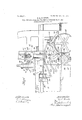
- Figure 1 represents a side elevation of the feed mechanism embodying my invention as applied to a metallamng machine, the view showing as much 0 such a machine as is necessary to illustrate the application of the invention.
- Fi 2 represents atransverse vertical section 0 the plan ngmachine, showing the feed mechanism in front elevation;
- Fig. 3 represents an en- 'larged end elevation, showing the feed mechon the usual guides.
- 20 is he reciprocating platen of a planing-machine, to which the mechanism constituting my invention is applied, adapted to hold.
- the work and mounted Said platen is driven by a main drive-shaft 21, having a inion 22 ineshin with a ear 23 on the leftand side of the p aner-b said gear being attached to a counter-shaft 24, having a pinion 25 mesh- With gear 26, supported in bearings mounted on the machine-frame, which engages a rack 27, Fig. 2, on the under side of the laten.
- T e'shaft 21 carries a fast drivintg-pulle 28, loose pulleys 29 30, and another ast pu ley 31, flanked by a loose pulley 32.
- the respective pulleys receive motion from thebelts 33 34 35, whic imparts the forward or cutting stroke to the platen, a slow-return movement to the platen at the beginning and end of the non-cutting stroke, and a quick-return move ment to the platen during the remainder of this stroke by engagement with the various pulleys at the proppr times, such engagement elt-shifters 36 37 44, controlling the severalbelts and operated through cam 42, link '49, and trip-lever 50, pivoted to the planer-bed 51 by suitable dogs carried by supports 56 60, mounted on the platen.
- 71 is the cross-feed saddle carrying the cutting-tool 72 and fed by a screw 73,journa1ed in the vertically-adjustable beam 74 andopcrating in a nut on the cutter-saddle in the usual manner.
- the mechanism by which the screw '73 is operated stepby ste by the driving mechanism to feed the sa die and tool constitutes the substance of the present invention and is constructed and arranged as follows:
- ratchet-wheel 77 On the end of screw 73 is a pinion 75, meshing with a gear 76, to which is fixed a toothed ratchet-wheel 77, as best seen in Figs. 3 and 4.
- this ratchet-wheel has usually been fed step by step by an ordinary pawl yieldingly in contact with the ratchet.
- the rack 81 j meshes with-a pinionh88; Fig. A, on ashort shaft 89, carried. bythe beam 74.
- On the outer en'cli of this shaft is aflixed an arm or finger ,90, adapted to engage heels or projections 91 on the shafts oftwo oppositely-act- ,ing pawls 92, pi voted to the friction support Y 79. These pawls have substantially radial.
- Such a shaft as to; a vibrating. arm.
- a separately-reciprocable driver having provisions to e gage and impart such movements in succession to the pawl, and yielding means holding the pawl free of the ratchet when free from engagement by the driven 3.
- a feeding element yielding means holding said element, normally retracted from operative position for rotating said member, means to move said element into operative position and feed said member, and a disabling device for said feeding element adap t ed to hold the same out of operative position and resist the action of said means.
- a plu rality of feeding elements mounted independently of the driver intermediate the driver and tool-holder and arranged to be' alternately engaged by the driver in its opposite movements, said elements being connectable with the tool-holder and movable to feed the latter when engaged by the driver, and dis-.
- abling devices for independentlyrestraining either element from connection with the holder, whereby the feeding elements may be alternately operated by the driver in its opposite movements for connection of one of them at different points with the tool-holder to feed the latter.
- a driver movable in opposite directions arranged to engage said pawls alternately, to
Landscapes
- Engineering & Computer Science (AREA)
- Mechanical Engineering (AREA)
- Portable Nailing Machines And Staplers (AREA)
Description
No. 836,631. PATENTED-NOV. 20, 1906.
D. L. CHANDLER. TOOL FEBDMEGHA'NISM FOR METAL WORKING MACHINES.
APPLICATION IILED JUNE 29, 1905.
PATENTED NOV. 20, 1906.
D. L. CHANDLER.
APPLICATION FILED JUNE 29, 1905.
' s SHEBTS-SHEET z.
I i [:3] s
M) I']Z% TOOL FEED MECHANISM FOR METAL WORKING MACHINES.
No 836,631. PATENTEDNUV. 20, 1966.
D. L: CHANDLER.
.TODL FEED MECHANISM FOR METAL WQEKING MACHINES.
APPLICATIOH FILED JUNE 29, 1905.
3 SHEETS-SHEET S f A) w w UNITED STATES PATENT OFFICE.
DANIEL L. CHANDLER, OFI'AIYER, MASSACHUSETTS. TOOL-FEED MECHANISMFQR METAL-WORKING MACHINES.
Specification of Letters Patent.
Patented Nov. 20, 1906.
Original application filed April 14, 1904, Serial No; 203,145. Divided and this application filed June 29, 1905. Serial No. 267.534.
To all whomw't may concern.-
Be it known that I, DANIELYL. CHANDL R, of Ayer, in the county of Middlesex and State of Massachusetts, have invented certain new and useful Improvements in Tool-Feed Mechanisms for Metal-Workin Machines, of which the following is a speci cation.
This invention relates to feeding mechanisms for the cuttin -tools of metal-workin machines, particular y planin '-machines, an is a division of a pending ap ication filed by me April 14, 1904, Serial go. 203,145, for planer. 1 r
The invention consists in a feeding mechanism of the character above stated, and has for its object to provide an improved mech anism by which the operator may quickly adjust the tool by hand when necessary,
particularly in backing out, or moving the tool in a direction contrary to the feed, and
' may vary the amount of feed of the tool while the machine is running. The application for which this mechanism is. more par ticularly adapted is for feeding the tool of a planer either across the machine vertically or in any other direction, but especially for furnishing the cross-feed, and in the following description and the drawings accompanying the same it is shown as applied to such a machine but it is-not limited to such use and may be employed in connection withany machine performing a series of identical operations whether continuously or intermittently, in which the tool must be advanced step by ste 8f the drawings, Figure 1 represents a side elevation of the feed mechanism embodying my invention as applied to a metallamng machine, the view showing as much 0 such a machine as is necessary to illustrate the application of the invention. Fi 2 represents atransverse vertical section 0 the plan ngmachine, showing the feed mechanism in front elevation; Fig. 3 represents an en- 'larged end elevation, showing the feed mechon the usual guides.
The same reference characters indicate the same parts in all the figures. In the drawings, 20 is he reciprocating platen of a planing-machine, to which the mechanism constituting my invention is applied, adapted to hold. the work and mounted Said platen is driven by a main drive-shaft 21, having a inion 22 ineshin with a ear 23 on the leftand side of the p aner-b said gear being attached to a counter-shaft 24, having a pinion 25 mesh- With gear 26, supported in bearings mounted on the machine-frame, which engages a rack 27, Fig. 2, on the under side of the laten.
T e'shaft 21 carries a fast drivintg-pulle 28, loose pulleys 29 30, and another ast pu ley 31, flanked by a loose pulley 32. The respective pulleys receive motion from thebelts 33 34 35, whic imparts the forward or cutting stroke to the platen, a slow-return movement to the platen at the beginning and end of the non-cutting stroke, and a quick-return move ment to the platen during the remainder of this stroke by engagement with the various pulleys at the proppr times, such engagement elt-shifters 36 37 44, controlling the severalbelts and operated through cam 42, link '49, and trip-lever 50, pivoted to the planer-bed 51 by suitable dogs carried by supports 56 60, mounted on the platen.
71 is the cross-feed saddle carrying the cutting-tool 72 and fed by a screw 73,journa1ed in the vertically-adjustable beam 74 andopcrating in a nut on the cutter-saddle in the usual manner.
The mechanism by which the screw '73 is operated stepby ste by the driving mechanism to feed the sa die and tool constitutes the substance of the present invention and is constructed and arranged as follows:
On the end of screw 73 is a pinion 75, meshing with a gear 76, to which is fixed a toothed ratchet-wheel 77, as best seen in Figs. 3 and 4. Heretofore this ratchet-wheel has usually been fed step by step by an ordinary pawl yieldingly in contact with the ratchet. With such a construction when it becomes necessary to back out the tool 72 by handthat is, move it in a direction contrary to the feed-by fitting a crank to the squaredend of the screw 73 the operatorhas been required to lift the pawl and rotate the crank and screw, the operati n being a somewhat difficult and time-consuming one and usually requiring the operatorfs two hands to perform it; but by the impro vedconstruction now to be described I avoid the diflicult operation heretofore re wired and allow thepowerfeed to be release and the tool backed opt withfohe'hand. On'the sleeve 78, to which the gear 76 and ratchet 77 are fixed, is mountedia'pawl-s '=pport 79', havinga split hub frictionally embracing the sleeve.-
81, Fig. 1, is the usual cross-feed rack operatedby link 82, lever 83,, and link '84 on a ig 'wrist on the friction-collar 86, embracing a drum. 87,-on the shaft 24.: The rack 81 j meshes with-a pinionh88; Fig. A, on ashort shaft 89, carried. bythe beam 74. On the outer en'cli of this shaft is aflixed an arm or finger ,90, adapted to engage heels or projections 91 on the shafts oftwo oppositely-act- ,ing pawls 92, pi voted to the friction support Y 79. These pawls have substantially radial.
noses engaging the teeth of-ratchet 77 and are-provided with projections 93, connected by a,spring194, which tends to throw the pawls out of engagement with the teeth ofthe ratchet.
. v abling either pawl and, allowing the other pawlto feed the tool in the directiomdesired. The rack 81', recei ving-motion from friction collar 86, oscillates the. finger 90,which engages the operativepawl ,and throws it into engageinent withthe ratchet 177, andifeeds said ratchet 'a distant a'vdepending upon the length of stroke of the racklthe friction of support 79 on collar being such as to permit this ac.- f'
, tion to take place. On the back stroke offinger it encounters the heel-piece 91 of the i V a fresh'operative stroke.- 7 a I I 5 It will be seen that the. operative pawl 92 V fisunder" strain only at the moment of feed. This strain may be'relie ved at any time it is desired by the'operator to feed by hand by applying the hand-crank to screw 3 and giving;
- cient to relieve the friction between ratchet 77, and pawl 9 2,whereupon-the pawl will be automatically released from engagement with theratchet by the action of its spring 94, and the-tool will be therebyfreed from the automatic feed and may be fed by hand in either direction. inmost casesbe sufficient to'relievethe pawl immediately after its feeding movement;
96 is .a shaftfon beam74j splined to gearing in the saddle 71 in ,the usual manner, whereby a vertical feed is imparted to the tool 72 upon removing the pinion 75 and substituting a f pinionon shaft 96 to mesh with gear 76. It
iadapted to engage any one of a'seg'ment of Eccentrics are provided for dise.
operative pawl and relieves the strain on, the operative pawl,- whereupon the spring 94 retracts the latter from engagement, with ratchet. 77 and the support 79 is retracted for equally as Well when connected to am.
.such a shaft: as to; a vibrating. arm.
the latter a slight kick ahead merely sufii 't'ary feeding member movables v v .advance saidh older, afeedinggelementi far Inertia and recoil will also,
will be understood, therefore, that my im- 65 provement applies to the vertical or other feed of the tool as well as to -the horizontal feed thereof. a
The friction of collar 86 on its drum 87 is furnished-by a spring 9 8,Fig. 5. The collar is opened at each end of its stroke to relieve this friction by. a cam-strut 99; operating be tween the limbs of the collar and having an arm 100 alternately engaging, two pins 101 102' as the drum is oscillated to and fro by 75 the reversed movements-of shaft24. I mount the pin 102 upon a hand-lever 103, adjustable about the axissofshaft-24' and having alocking-pinA- :1 04 at its upper end 80 holes 1-05 105, formed in the side of:theplaner-bed. By the foregoing arrangement While the planer is running the operator may adjust the stroke of rack 81,?and hence the length of the cross-feed movement at each 85 reciprocation of theJplaner-platen from nothingvto a' maximum by swinging the lever 108 so asto bring its pin 102 nearer to or farther from the fixed pin 101.} y 1 I do not broadly claim the friction-box automatically opened by lstationary abutments, sin ce heretofore it hasbeen a commen practiceto provide sueha bossequipped with a wrist-pin of 1' adjustable radial position buit.suchconstruction-made it necessary or 9 5 desirable to stop the; planer whenever a new adjustment was to .be iobtained gthereb r causing loss oflmore or less time It-Will be seen that my invention saves much time over such a device; g 2' It; is obvious thatthe pawlrand -ratchet mechanism and the rack 81 might beagplied roe vdoes that here shown for the lin ed to produce reciprocationit in the itto be understood, therefore, tha vention is applicable to a wide aeaniet p chines and is not limited in its users 1p ticular'one;
-.I claim-+4 .7 -1; The chmbinatio'nof "Ma d"; 3:5 by step to rotating said member, yielding means'tend ing' to hold'said 'elementretiiacted firom (open at ve relation with thejmember, and a seam rate "driver movable relatively to the element to engage and place the same in operativeres lation with the member and thegiradvance the. element and membenfff 2. The OOlnblIlfiQtilQiliOf: Ia
eel-holder, a ratchet to feed the fsam'e',"'af
wl having a movement relatively to the ratchet to enga e the same and a further movement .to,feeIl,
and a separately-reciprocable driver having provisions to e gage and impart such movements in succession to the pawl, and yielding means holding the pawl free of the ratchet when free from engagement by the driven 3. The combination of a tool-holder, a ratchet to feed the same, phwl having ratchet-engaging and ratchet-feeding movements, yielding means normally holding said pawl retracted, an oscillatory driver adapted to successively impart said movements to the pawl, and a support for said pawl independ ent of the driverand having africtional connection with the ratchet.
4. The combination of a tool holder, a rotary member having a step-by-step motion for imparting feed movement to said holder,
. a feeding element, yielding means holding said element, normally retracted from operative position for rotating said member, means to move said element into operative position and feed said member, and a disabling device for said feeding element adap t ed to hold the same out of operative position and resist the action of said means.
' 5. The combination of a tool-holder, a driver movable in opposite directions, and'a plurality of feeding elements intermediate the driver and tool-holder and arranged to be alternately engaged by the driver in its opposite movements, said elements being connectable with the tool-holder and movable to feedthe latter when engaged by the driver, andeach adapted to be independently restrained from connection with the holder, and means for so restraining the, feeding elements, whereby the driver in its oppositemovements is enabled to ad vance the holder intermittently. a v I 6. The-combination of a tool holder, a
driver movable in opposite'directions, a plu rality of feeding elements mounted independently of the driver intermediate the driver and tool-holder and arranged to be' alternately engaged by the driver in its opposite movements, said elements being connectable with the tool-holder and movable to feed the latter when engaged by the driver, and dis-.
abling devices for independentlyrestraining either element from connection with the holder, whereby the feeding elements may be alternately operated by the driver in its opposite movements for connection of one of them at different points with the tool-holder to feed the latter.
7. The combination of 'a "tool-holder, a ratchet to feed the same, a plurality ofoppositely-arranged pawls for engaging and feeding the ratchet, yielding means connect ed to said pawls tending to retain them. out of operative relation to the ratchet, adriver independent ofsaid pawls and arranged-batween them, movable in opposite di ections to engage said pawls alternately, and connect erated to retain either of said feeding elements out of operative connection with the tool-holder, and yielding means tending always to hold the feeding elements out of such connection.
9. The combination of a tool-holder, a ratchet for feeding the same, a pawl-holder, oppositoly-arranged pawls on said holder adapted to engage and feed the ratchet, yielding means connected to said pawls tending to retain them out of engagement with the ratchet, a driver movable in opposite directions and having a projection between the pawls for engaging them alternately, and an independent positive disabling device for each paw-l adapted to retain the respective pawl out of connection with the ratchet.
10. The combination of a tool-holder, a ratchet'for feeding the same, a pawl-holder, oppositely-arranged pawls on said holder adapted to engage and feed the ratchet, yielding means connected to said pawls tending to retain them out of engagement with the ratchet, independent positive disabling devices for the awls adapted to be adjusted to hold one of t e pawls out of operative relation with the ratchet, rendering said pawl in active, the 'other pawl remaining active, and
a driver movable in opposite directions arranged to engage said pawls alternately, to
move the pawl-holder in opposite directions and'periodlcally connect the active pawl with the ratchet.
11: The combination of a tool-holder, a ratchet to feed the same, a pawl-holder movable about the axis of the ratchet, oppositelyarranged pawls pivoted to the pawl-holder for engaging and feeding the ratchet and each having a projection, a spring connecting said projections and tending to hold the pawls out of engagement with the ratchet, an oscillatory driver having an arm projecting between said pawls and adapted to engage the projections thereofalternately, to move the paiwls'into engagement with, and thereafter feed'the ratchet, and an independent positive device mounted adjacent each pawl adapted to'be engaged therewith and to retain said pawl out of engagement with the ratchet.
12. The cbmbination of a tool-holder, a reversely-rotating shaft having a friction- =='-d rnm;--afriction collar' onsaid drum, a trip device for relieving the friction of said collar, abutments for engaging said trip device at opposite ends of its stroke, an arm carrying carrying one of said abutments movable into one of saidabutm'ents, and means for fixing a variety of different positions, whereby the said arm in a variety of angular positions, distance between the abutments may be vavwherelliy its abutment is located at different ried to adjust the amount, of travel of the '5 distances from the other abutrnent. drum.
7 13. The combination of a tool-holder, a- In testimony whereof I have affixed 'my reversely-rotating shaft having a frictionsignature in presence of two witnesses. drum, 9; friction-collar on said drum, a trip de- 1 DANIEL L. CHANDLER. vice .forrelieving the friction of said collar, Witnesses:
to. abutments for engaging said-trip device at O. F. BROWN,
opposite. ends ofits strokeyand aI rnember GEO. J. BURNS.
Priority Applications (1)
| Application Number | Priority Date | Filing Date | Title |
|---|---|---|---|
| US267534A US836631A (en) | 1904-04-14 | 1905-06-29 | Tool-feed mechanism for metal-working machines. |
Applications Claiming Priority (2)
| Application Number | Priority Date | Filing Date | Title |
|---|---|---|---|
| US20314504A US826476A (en) | 1904-04-14 | 1904-04-14 | Planer. |
| US267534A US836631A (en) | 1904-04-14 | 1905-06-29 | Tool-feed mechanism for metal-working machines. |
Publications (1)
| Publication Number | Publication Date |
|---|---|
| US836631A true US836631A (en) | 1906-11-20 |
Family
ID=2905105
Family Applications (1)
| Application Number | Title | Priority Date | Filing Date |
|---|---|---|---|
| US267534A Expired - Lifetime US836631A (en) | 1904-04-14 | 1905-06-29 | Tool-feed mechanism for metal-working machines. |
Country Status (1)
| Country | Link |
|---|---|
| US (1) | US836631A (en) |
-
1905
- 1905-06-29 US US267534A patent/US836631A/en not_active Expired - Lifetime
Similar Documents
| Publication | Publication Date | Title |
|---|---|---|
| US836631A (en) | Tool-feed mechanism for metal-working machines. | |
| US1299717A (en) | Feed mechanism. | |
| US730445A (en) | Machine for relieving-tools. | |
| US731870A (en) | Indexing mechanism. | |
| US1023268A (en) | Shaping-machine. | |
| US808887A (en) | Screw-making and metal-turning lathe. | |
| US826476A (en) | Planer. | |
| US459629A (en) | Shaping-machine | |
| US1275404A (en) | Portable shaper. | |
| US586922A (en) | Island | |
| US1478334A (en) | Profiling machine | |
| US787510A (en) | Circular sawing machine. | |
| US1830309A (en) | Cam controlled shaper feed | |
| US1360842A (en) | Heading-machine | |
| US2312115A (en) | Thread cutting machine | |
| US1199252A (en) | Automatic turrett-lathe. | |
| US1905560A (en) | Drilling machine | |
| US551066A (en) | Machine for making milling-cutters | |
| US410403A (en) | Boabds feom logs | |
| US1221844A (en) | Combined shaping and milling machinery. | |
| US835356A (en) | Sawmill. | |
| US628734A (en) | Speed-changing mechanism for screw-machines. | |
| US843615A (en) | Machine for refacing valve-seats. | |
| US447820A (en) | richter | |
| US1009948A (en) | Metal-working machine. |