US8254062B2 - Recessed base plate for data transducer suspension - Google Patents
Recessed base plate for data transducer suspension Download PDFInfo
- Publication number
- US8254062B2 US8254062B2 US12/491,951 US49195109A US8254062B2 US 8254062 B2 US8254062 B2 US 8254062B2 US 49195109 A US49195109 A US 49195109A US 8254062 B2 US8254062 B2 US 8254062B2
- Authority
- US
- United States
- Prior art keywords
- structural element
- structural
- assembly
- suspension assembly
- microactuator
- Prior art date
- Legal status (The legal status is an assumption and is not a legal conclusion. Google has not performed a legal analysis and makes no representation as to the accuracy of the status listed.)
- Expired - Fee Related, expires
Links
- 239000000725 suspension Substances 0.000 title claims abstract description 62
- 229910001220 stainless steel Inorganic materials 0.000 claims description 4
- 239000010935 stainless steel Substances 0.000 claims description 4
- 230000002463 transducing effect Effects 0.000 abstract description 5
- 239000003351 stiffener Substances 0.000 description 35
- 230000009977 dual effect Effects 0.000 description 10
- 238000000034 method Methods 0.000 description 4
- 230000035939 shock Effects 0.000 description 4
- 230000008569 process Effects 0.000 description 3
- 239000000463 material Substances 0.000 description 2
- RYGMFSIKBFXOCR-UHFFFAOYSA-N Copper Chemical compound [Cu] RYGMFSIKBFXOCR-UHFFFAOYSA-N 0.000 description 1
- 239000004642 Polyimide Substances 0.000 description 1
- 239000000853 adhesive Substances 0.000 description 1
- 230000001070 adhesive effect Effects 0.000 description 1
- 230000000712 assembly Effects 0.000 description 1
- 238000000429 assembly Methods 0.000 description 1
- 230000008859 change Effects 0.000 description 1
- 238000005352 clarification Methods 0.000 description 1
- 229910052802 copper Inorganic materials 0.000 description 1
- 239000010949 copper Substances 0.000 description 1
- 230000000694 effects Effects 0.000 description 1
- 238000005530 etching Methods 0.000 description 1
- 230000007246 mechanism Effects 0.000 description 1
- 238000012986 modification Methods 0.000 description 1
- 230000004048 modification Effects 0.000 description 1
- 229920001721 polyimide Polymers 0.000 description 1
- 230000009467 reduction Effects 0.000 description 1
- 230000004044 response Effects 0.000 description 1
- 238000003466 welding Methods 0.000 description 1
Images


Classifications
-
- G—PHYSICS
- G11—INFORMATION STORAGE
- G11B—INFORMATION STORAGE BASED ON RELATIVE MOVEMENT BETWEEN RECORD CARRIER AND TRANSDUCER
- G11B5/00—Recording by magnetisation or demagnetisation of a record carrier; Reproducing by magnetic means; Record carriers therefor
- G11B5/48—Disposition or mounting of heads or head supports relative to record carriers ; arrangements of heads, e.g. for scanning the record carrier to increase the relative speed
- G11B5/4806—Disposition or mounting of heads or head supports relative to record carriers ; arrangements of heads, e.g. for scanning the record carrier to increase the relative speed specially adapted for disk drive assemblies, e.g. assembly prior to operation, hard or flexible disk drives
- G11B5/4833—Structure of the arm assembly, e.g. load beams, flexures, parts of the arm adapted for controlling vertical force on the head
-
- G—PHYSICS
- G11—INFORMATION STORAGE
- G11B—INFORMATION STORAGE BASED ON RELATIVE MOVEMENT BETWEEN RECORD CARRIER AND TRANSDUCER
- G11B5/00—Recording by magnetisation or demagnetisation of a record carrier; Reproducing by magnetic means; Record carriers therefor
- G11B5/48—Disposition or mounting of heads or head supports relative to record carriers ; arrangements of heads, e.g. for scanning the record carrier to increase the relative speed
- G11B5/4806—Disposition or mounting of heads or head supports relative to record carriers ; arrangements of heads, e.g. for scanning the record carrier to increase the relative speed specially adapted for disk drive assemblies, e.g. assembly prior to operation, hard or flexible disk drives
- G11B5/4873—Disposition or mounting of heads or head supports relative to record carriers ; arrangements of heads, e.g. for scanning the record carrier to increase the relative speed specially adapted for disk drive assemblies, e.g. assembly prior to operation, hard or flexible disk drives the arm comprising piezoelectric or other actuators for adjustment of the arm
-
- G—PHYSICS
- G11—INFORMATION STORAGE
- G11B—INFORMATION STORAGE BASED ON RELATIVE MOVEMENT BETWEEN RECORD CARRIER AND TRANSDUCER
- G11B5/00—Recording by magnetisation or demagnetisation of a record carrier; Reproducing by magnetic means; Record carriers therefor
- G11B5/48—Disposition or mounting of heads or head supports relative to record carriers ; arrangements of heads, e.g. for scanning the record carrier to increase the relative speed
- G11B5/54—Disposition or mounting of heads or head supports relative to record carriers ; arrangements of heads, e.g. for scanning the record carrier to increase the relative speed with provision for moving the head into or out of its operative position or across tracks
- G11B5/55—Track change, selection or acquisition by displacement of the head
- G11B5/5521—Track change, selection or acquisition by displacement of the head across disk tracks
- G11B5/5552—Track change, selection or acquisition by displacement of the head across disk tracks using fine positioning means for track acquisition separate from the coarse (e.g. track changing) positioning means
-
- G—PHYSICS
- G11—INFORMATION STORAGE
- G11B—INFORMATION STORAGE BASED ON RELATIVE MOVEMENT BETWEEN RECORD CARRIER AND TRANSDUCER
- G11B5/00—Recording by magnetisation or demagnetisation of a record carrier; Reproducing by magnetic means; Record carriers therefor
- G11B5/48—Disposition or mounting of heads or head supports relative to record carriers ; arrangements of heads, e.g. for scanning the record carrier to increase the relative speed
- G11B5/58—Disposition or mounting of heads or head supports relative to record carriers ; arrangements of heads, e.g. for scanning the record carrier to increase the relative speed with provision for moving the head for the purpose of maintaining alignment of the head relative to the record carrier during transducing operation, e.g. to compensate for surface irregularities of the latter or for track following
- G11B5/596—Disposition or mounting of heads or head supports relative to record carriers ; arrangements of heads, e.g. for scanning the record carrier to increase the relative speed with provision for moving the head for the purpose of maintaining alignment of the head relative to the record carrier during transducing operation, e.g. to compensate for surface irregularities of the latter or for track following for track following on disks
Definitions
- head positioning is accomplished by operating an actuator arm with a large scale actuation motor, such as a voice coil motor, to position a head on a flexure at the of the suspension arm.
- a large scale actuation motor such as a voice coil motor
- the large scale motor lacks sufficient resolution to effectively accommodate high data density.
- a high resolution head positioning mechanism, or microactuator is advantageous to accommodate the high data density.
- a device that has a small vertical thickness.
- a piezoelectric element and a suspension stiffening element are employed that increase vertical thickness. Increased vertical thickness limits the interconnect options to the piezoelectric element and also has a negative effect on the shock performance of the device, in addition to increasing the weight and footprint of the device.
- a design that allows for dual stage actuation with reduced vertical thickness compared to prior dual stage designs would be desirable.
- the present invention is directed to a suspension assembly for a data transducing system that includes a dual-stage actuation system for positioning a data transducer.
- a first structural element of the suspension assembly includes a plate portion and a boss tower that is connectable to a main actuator of the dual-stage actuation system.
- a second structural element of the suspension assembly includes a recess that receives the plate portion of the first structural element, an opening through which the boss tower extends for connection to the main actuator of the dual-stage actuation system, and a flexible region to which a microactuator element of the dual-stage actuation system is connected.
- the suspension assembly also includes a support structure connected to the flexible region of the second structural element that carries the data transducer, and an electrical circuit connection system for making electrical connections to the data transducer and to the microactuator of the dual-stage actuation system.
- FIG. 1 is a top view of a suspension assembly according to an embodiment of the present invention used with a first version of a dual stage actuation system.
- FIG. 2 is a bottom view of the suspension assembly shown in FIG. 1 .
- FIG. 3 is a top perspective view of the suspension assembly shown in FIG. 1 .
- FIG. 4 is a bottom perspective view of the suspension assembly shown in FIG. 1 .
- FIG. 5 is a top view of a suspension assembly according to an embodiment of the present invention used with a second version of a dual stage actuation system.
- FIG. 6 is a bottom view of the suspension assembly shown in FIG. 5 .
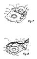
- FIG. 7 is a top perspective view of the suspension assembly shown in FIG. 5 .
- FIG. 8 is a bottom perspective view of the suspension assembly shown in FIG. 5 .
- FIG. 9 is a side view of a suspension assembly according to an embodiment of the present invention, showing its total vertical thickness.
- FIG. 10 is a side view of a suspension assembly according to another embodiment of the present invention, showing its total vertical thickness.
- FIG. 11 is a side view of a different suspension assembly, showing its total vertical thickness.
- FIG. 1 is a top view
- FIG. 2 is a bottom view
- FIG. 3 is a top perspective view
- FIG. 4 is a bottom perspective view, of suspension assembly 10 according to an embodiment of the present invention, used with a first version of a dual stage actuation system.
- the dual stage actuation system employs a main actuator (not shown) for coarse positioning of data transducer 12 via movement of an actuator arm (not shown) that connects to suspension 10 , and also employs microactuator element 14 for fine, higher resolution positioning of data transducer 12 .
- a main actuator not shown
- microactuator element 14 for fine, higher resolution positioning of data transducer 12 .
- microactuator element 14 is a piezoelectric element that is responsive to electrical signals to move the support assembly that carries data transducer 12 , which includes load beam 16 and flexure 18 .
- Data transducer 12 is electrically connected via conductive traces carried by flex circuit 20 .
- the location of transducer 12 on suspension 10 shown in FIG. 1 is just one possible embodiment; for example, transducer 12 could be located further away from load beam 16 on flexure 18 in some embodiments.
- microactuator element 14 may require stiffener 22 to be employed so that data transducer 12 can be positioned with the required frequency and resonance response needed to effectively read and write data.
- stiffener 22 In many prior designs, the stiffener and the base plate (for connection to the actuator arm) each had a vertical height of 5 milli-inches (mils) or more, so that the total vertical height of the suspension assembly would be well over 10 mils. In some applications, this results in a stiffener-to-media clearance that is quite small, resulting in poor shock resistance performance, and limiting the options for electrical interconnection to the microactuator element.
- suspension assembly 10 employs stiffener 22 having recess 24 , within which base plate 26 is located.
- Boss tower 28 extends through opening 30 in stiffener 22 for connection to the actuator arm in a conventional manner, although boss tower 28 has more vertical height than in prior designs because it extends through stiffener 22 .
- Stiffener 22 may include asymmetrical mounting tabs for connection to symmetrically located microactuator element 14 .
- base plate 26 and microactuator element 14 are both located proximate the same side of stiffener 22 (opposite the actuator arm), in recessed areas of stiffener 22 .
- This configuration reduces the vertical height of suspension assembly 10 , and also reduces the total weight of suspension assembly due to the removal of material from stiffener 22 , with only a minimal penalty in the resonance performance of suspension assembly 10 (which is compensated for by the use of microactuator element 14 to achieve fine positioning with high frequency performance).
- the reduced vertical height and weight of suspension assembly 10 improves the shock resistance of the device.
- Base plate 26 is shown having a generally circular shape, which minimizes the total area of base plate 26 and of generally corresponding recess 24 in stiffener 22 for receiving base plate 26 .
- base plate 26 may have other shapes and sizes (such as polygons, ovals, etc.), and recess 24 in stiffener 22 may have a shape and size which generally corresponds to the shape and size of base plate 26 .
- Other variations in the relationship between the shape and size of base plate 26 and recess 24 in stiffener 22 are contemplated by the present invention as well.
- FIG. 5 is a top view
- FIG. 6 is a bottom view
- FIG. 7 is a top perspective view
- FIG. 8 is a bottom perspective view, of suspension assembly 10 according to an embodiment of the present invention, used with a second version of a dual stage actuation system.
- the system shown in FIGS. 5-8 is nearly identical to the system shown in FIGS. 1-4 , except that dual microactuator elements 14 a and 14 b ( FIGS. 5-8 ) are used in place of microactuator element 14 shown in FIGS. 1-4 .
- Stiffener 22 a ( FIGS. 5-8 ) is a reconfigured version of stiffener 22 shown in FIGS. 1-4 to account for the use of dual microactuator elements 14 a and 14 b .
- microactuator element 14 in FIGS. 1-4 was shown as being located in a recessed portion of stiffener 22
- microactuator elements 14 a and 14 b in FIGS. 5-8 are located proximate the side opposite data transducer 12 of stiffener 22 a . In other embodiments, more than two microactuator elements may be used.
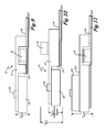
- FIGS. 9 and 10 are side views of suspension assembly 10 according to embodiments of the present invention
- FIG. 11 is a side view of a non-recessed base plate suspension assembly, showing the total vertical thickness of both assemblies for purposes of comparison. Vertical thickness is measured from a high point where the actuator arm attaches to the suspension, to a low point at the interface between the stiffener and load beam (with the lowest component typically being the flex circuit), shown in FIGS. 9-11 as T Vert .
- the configuration shown in FIG. 9 employs microactuator element 14 on the bottom of a recessed portion of stiffener 22
- the configuration shown in FIG. 10 employs microactuator element 14 on top of stiffener 22 .
- suspension assembly 10 allows the total vertical thickness T Vert of suspension assembly 10 to be reduced to less than 10 mils.
- suspension assembly 10 has a total vertical thickness T Vert of about 8.5 mils.
- suspension assembly 10 ( FIG. 9 ) includes stiffener 22 (5.9 mils), base plate 26 (5 mils), load beam 16 (1 mil), and flex circuit 20 (1.6 mils).
- Flex circuit 20 includes a stainless steel layer (0.7 mils), a polyimide layer (0.4 mils), and a copper layer (0.5 mils).
- the vertical thickness of suspension assembly 10 is composed of stiffener 22 , load beam 16 , and flex circuit 20 ; base plate 26 does not add to the vertical thickness because it is located in recess 24 of stiffener 22 .
- the configuration of suspension assembly 10 shown in FIG. 10 has also has a low vertical thickness T Vert-Suspension-Region (less than 10 mils) in the region near boss tower 28 , due to base plate 26 being located in recess 24 of stiffener 22 .
- the vertical thickness T Vert in the region where microactuator 14 is attached to stiffener 22 is greater than in the configuration shown in FIG. 9 , but vertical thickness is a less important parameter in that region of suspension 10 , and the greater vertical thickness in that region is acceptable in many applications.
- the non-recessed base plate suspension assembly shown in FIG. 11 has a total vertical thickness T Vert of about 12.6 mils.
- the non-recessed base plate suspension assembly shown in FIG. 11 includes stiffener 122 (5 mils), base plate 126 (5 mils), load beam 116 (1 mil), and flex circuit 120 (1.6 mils). In this assembly, base plate 126 and stiffener 122 both add to the total vertical thickness.
- Stiffener 22 shown in FIGS. 9 and 10 is thicker than stiffener 122 shown in FIG. 11 (e.g., by 0.9 mils). This additional thickness is provided to improve the resonance performance of suspension assembly 10 , resulting in only a small reduction in resonance performance for the configuration shown in FIGS. 9 and 10 compared to the configuration shown in FIG. 11 .
- flex circuit 20 may be moved to the top of stiffener 22 in the region adjacent base plate 26 .
- flex circuit 20 passes through an opening in stiffener 22 or load beam 16 to reach the bottom of load beam 16 where the data transducer is carried.
- This configuration results in a lower vertical thickness component from stiffener 22 to the media (which in many systems is the dimension of interest for shock resistance), although its assembly is slightly more complex.
- stiffener 22 and base plate 26 are both composed of stainless steel.
- Base plate 26 is typically formed by a stamping process, while stiffener 22 (and specifically, recess 24 in stiffener 22 ) is formed by a process such as etching.
- Boss tower 28 is typically connected to the actuator arm by a process such as swaging, as is known in the art.
- Base plate 26 may be attached to stiffener 22 in a number of ways, including by laser welding, conductive adhesive, or other attachment methods generally known in the art.
Landscapes
- Supporting Of Heads In Record-Carrier Devices (AREA)
- Moving Of The Head To Find And Align With The Track (AREA)
Abstract
Description
Claims (19)
Priority Applications (3)
| Application Number | Priority Date | Filing Date | Title |
|---|---|---|---|
| US12/491,951 US8254062B2 (en) | 2008-10-20 | 2009-06-25 | Recessed base plate for data transducer suspension |
| PCT/US2010/039484 WO2010151538A1 (en) | 2009-06-25 | 2010-06-22 | Recessed base plate for data transducer suspension |
| JP2012517652A JP5615356B2 (en) | 2009-06-25 | 2010-06-22 | Recessed base plate for data transducer suspension |
Applications Claiming Priority (2)
| Application Number | Priority Date | Filing Date | Title |
|---|---|---|---|
| US12/254,671 US8144435B2 (en) | 2008-10-20 | 2008-10-20 | Cost reduced microactuator suspension |
| US12/491,951 US8254062B2 (en) | 2008-10-20 | 2009-06-25 | Recessed base plate for data transducer suspension |
Related Parent Applications (1)
| Application Number | Title | Priority Date | Filing Date |
|---|---|---|---|
| US12/254,671 Continuation-In-Part US8144435B2 (en) | 2008-10-20 | 2008-10-20 | Cost reduced microactuator suspension |
Publications (2)
| Publication Number | Publication Date |
|---|---|
| US20100097727A1 US20100097727A1 (en) | 2010-04-22 |
| US8254062B2 true US8254062B2 (en) | 2012-08-28 |
Family
ID=42731954
Family Applications (1)
| Application Number | Title | Priority Date | Filing Date |
|---|---|---|---|
| US12/491,951 Expired - Fee Related US8254062B2 (en) | 2008-10-20 | 2009-06-25 | Recessed base plate for data transducer suspension |
Country Status (3)
| Country | Link |
|---|---|
| US (1) | US8254062B2 (en) |
| JP (1) | JP5615356B2 (en) |
| WO (1) | WO2010151538A1 (en) |
Cited By (21)
| Publication number | Priority date | Publication date | Assignee | Title |
|---|---|---|---|---|
| US8570688B1 (en) * | 2010-11-08 | 2013-10-29 | Magnecomp Corporation | Electrical connections to a microactuator in a hard disk drive suspension |
| US8861141B2 (en) | 2012-08-31 | 2014-10-14 | Hutchinson Technology Incorporated | Damped dual stage actuation disk drive suspensions |
| US8891206B2 (en) * | 2012-12-17 | 2014-11-18 | Hutchinson Technology Incorporated | Co-located gimbal-based dual stage actuation disk drive suspensions with motor stiffener |
| US8896969B1 (en) | 2013-05-23 | 2014-11-25 | Hutchinson Technology Incorporated | Two-motor co-located gimbal-based dual stage actuation disk drive suspensions with motor stiffeners |
| US8896970B1 (en) * | 2013-12-31 | 2014-11-25 | Hutchinson Technology Incorporated | Balanced co-located gimbal-based dual stage actuation disk drive suspensions |
| US8896968B2 (en) | 2012-10-10 | 2014-11-25 | Hutchinson Technology Incorporated | Co-located gimbal-based dual stage actuation disk drive suspensions with dampers |
| US8941951B2 (en) | 2012-11-28 | 2015-01-27 | Hutchinson Technology Incorporated | Head suspension flexure with integrated strain sensor and sputtered traces |
| US9001471B2 (en) | 2012-09-14 | 2015-04-07 | Hutchinson Technology Incorporated | Co-located gimbal-based dual stage actuation disk drive suspensions |
| US9001469B2 (en) | 2012-03-16 | 2015-04-07 | Hutchinson Technology Incorporated | Mid-loadbeam dual stage actuated (DSA) disk drive head suspension |
| US9007726B2 (en) | 2013-07-15 | 2015-04-14 | Hutchinson Technology Incorporated | Disk drive suspension assembly having a partially flangeless load point dimple |
| US9070392B1 (en) | 2014-12-16 | 2015-06-30 | Hutchinson Technology Incorporated | Piezoelectric disk drive suspension motors having plated stiffeners |
| US9135936B1 (en) | 2014-03-22 | 2015-09-15 | Magnecomp Corporation | Microactuated suspension with spring bias acting on conductive adhesive bond for improved reliability |
| US9245555B2 (en) | 2010-05-24 | 2016-01-26 | Hutchinson Technology Incorporated | Low resistance ground joints for dual stage actuation disk drive suspensions |
| US9318136B1 (en) | 2014-12-22 | 2016-04-19 | Hutchinson Technology Incorporated | Multilayer disk drive motors having out-of-plane bending |
| US9431042B2 (en) | 2014-01-03 | 2016-08-30 | Hutchinson Technology Incorporated | Balanced multi-trace transmission in a hard disk drive flexure |
| US9646638B1 (en) | 2016-05-12 | 2017-05-09 | Hutchinson Technology Incorporated | Co-located gimbal-based DSA disk drive suspension with traces routed around slider pad |
| US9734852B2 (en) | 2015-06-30 | 2017-08-15 | Hutchinson Technology Incorporated | Disk drive head suspension structures having improved gold-dielectric joint reliability |
| US9824704B2 (en) | 2015-02-17 | 2017-11-21 | Hutchinson Technology Incorporated | Partial curing of a microactuator mounting adhesive in a disk drive suspension |
| US20190318762A1 (en) * | 2018-04-11 | 2019-10-17 | Magnecomp Corporation | Disk Drive Suspension Configured For Vertical Coupling And Windage Control |
| US20210295864A1 (en) * | 2020-03-19 | 2021-09-23 | Western Digital Technologies, Inc. | Swage plate assembly with swage boss insert |
| US11501797B2 (en) * | 2020-05-15 | 2022-11-15 | Magnecomp Corporation | Actuator joint with non-straight edge |
Families Citing this family (5)
| Publication number | Priority date | Publication date | Assignee | Title |
|---|---|---|---|---|
| JP2010225247A (en) * | 2009-03-25 | 2010-10-07 | Hitachi High-Technologies Corp | Magnetic head positioning device, magnetic head testing device, and magnetic disk testing device |
| US8498082B1 (en) | 2011-03-23 | 2013-07-30 | Magnecomp Corporation | DSA suspension with improved microactuator stroke length |
| US8310790B1 (en) | 2011-06-11 | 2012-11-13 | Nhk Spring Co., Ltd | Remote drive rotary head dual stage actuator |
| US8730621B2 (en) | 2012-07-09 | 2014-05-20 | Seagate Technology Llc | Solder ball bridge, and methods of making |
| US20220415347A1 (en) * | 2021-06-29 | 2022-12-29 | Seagate Technology Llc | Low force actuator with a coupler piece and constrained layer construction |
Citations (24)
| Publication number | Priority date | Publication date | Assignee | Title |
|---|---|---|---|---|
| JPS60136978A (en) * | 1983-12-26 | 1985-07-20 | Hitachi Ltd | Connecting structure of magnetic head support arm |
| US5805382A (en) | 1996-06-21 | 1998-09-08 | International Business Machines Corporation | Integrated conductor magnetic recording head and suspension having cross-over integrated circuits for noise reduction |
| US6063508A (en) * | 1998-02-25 | 2000-05-16 | Intri-Plex Technologies, Inc. | Swageable base plate with gram load offset and adjustment feature |
| US6215625B1 (en) | 1999-01-04 | 2001-04-10 | Read-Rite Corporation | Apparatus and method for adhesive bridge suspension attachment |
| JP2001126423A (en) * | 1999-10-27 | 2001-05-11 | Nec Corp | Magnetic head positioning mechanism |
| US6252743B1 (en) * | 1998-11-02 | 2001-06-26 | Read-Rite Corporation | Read/write positioning arm with interspaced amplifier chips |
| US20010043443A1 (en) | 2000-05-22 | 2001-11-22 | Nhk Spring Co., Ltd. | Suspension for disc drive |
| US6404593B1 (en) * | 2000-04-05 | 2002-06-11 | Magnecomp Corp. | Two-piece load beam mount system |
| US6469869B1 (en) | 2000-04-14 | 2002-10-22 | Magnecomp Corporation | Low mass baseplate for disk drive suspension |
| US6501625B1 (en) | 1999-06-29 | 2002-12-31 | Hutchinson Technology Incorporated | Disk drive suspension with multi-layered piezoelectric actuator controlled gram load |
| US6522624B2 (en) | 2001-05-03 | 2003-02-18 | Seagate Technology Llc | Attachment and microactuation aids in a laminated suspension |
| US6597538B1 (en) | 1999-12-15 | 2003-07-22 | Nhk Spring Co., Ltd. | Suspension for disk drive |
| US6961210B2 (en) | 2003-03-28 | 2005-11-01 | Esgw Holdings Limited | Data storage device with a low profile spindle motor |
| US7023667B2 (en) | 2002-10-07 | 2006-04-04 | Hitachi Global Storage Technologies Netherlands B.V. | Dual stage suspension with PZT actuators arranged to improve actuation in suspensions of short length |
| US20060221503A1 (en) * | 2005-03-31 | 2006-10-05 | Nhk Spring Co., Ltd. | Head suspension |
| US7224555B2 (en) | 2003-08-05 | 2007-05-29 | Nhk Spring Co., Ltd. | Disc drive suspension |
| US20080024927A1 (en) * | 2006-07-28 | 2008-01-31 | Samsung Electronics Co., Ltd. | Head gimbal assembly and hard disk drive having the same |
| US20090027807A1 (en) | 2007-07-25 | 2009-01-29 | Sae Magnetics (H.K.) Ltd. | Head gimbal assembly having balanced weight, disk drive unit with the same and manufacturing method thereof |
| US20090086379A1 (en) | 2007-09-27 | 2009-04-02 | Nhk Spring Co., Ltd. | Head suspension and piezoelectric actuator |
| US7554773B2 (en) | 2005-02-28 | 2009-06-30 | Sae Magnetics (H.K.) Ltd. | Micro-actuator, head gimbal assembly and disk drive unit with the same |
| US7624495B1 (en) | 2000-10-10 | 2009-12-01 | Maxtor Corporation | Method of reducing torque out retention values in de-swaging of actuator of disk drive |
| US20100073824A1 (en) * | 2008-09-19 | 2010-03-25 | Nhk Spring Co., Ltd. | Head suspension |
| US20100097726A1 (en) | 2008-10-20 | 2010-04-22 | Seagate Technology Llc | Cost reduced microactuator suspension |
| US7719798B2 (en) | 2006-02-14 | 2010-05-18 | Sae Magnetics (H.K.) Ltd. | Rotational micro-actuator integrated with suspension of head gimbal assembly, and disk drive unit with the same |
Family Cites Families (23)
| Publication number | Priority date | Publication date | Assignee | Title |
|---|---|---|---|---|
| US5225949A (en) * | 1992-02-26 | 1993-07-06 | Hewlett-Packard Company | Disk drive transducer suspension assembly of reduced thickness |
| US6372315B1 (en) * | 1998-01-07 | 2002-04-16 | Intri-Plex Technologies, Inc. | All-metal base plate having a pronged hub for press-in attachment of a load beam assembly to a head actuator arm of a disk drive |
| JP3926043B2 (en) * | 1998-08-07 | 2007-06-06 | 日本発条株式会社 | Manufacturing method of suspension for disk drive |
| US6160684A (en) * | 1998-11-12 | 2000-12-12 | Read-Rite Corporation | Head suspension having tabs and force isolation welds for gram load reduction during swaging |
| US6233124B1 (en) * | 1998-11-18 | 2001-05-15 | Seagate Technology Llc | Piezoelectric microactuator suspension assembly with improved stroke length |
| US6466412B1 (en) * | 1999-04-26 | 2002-10-15 | Hutchinson Technology Incorporated | Head suspension having tapered processing holes and method for aligning tooling during suspension manufacture |
| US6239953B1 (en) * | 1999-10-15 | 2001-05-29 | Magnecomp Corp. | Microactuated disk drive suspension with heightened stroke sensitivity |
| JP3744297B2 (en) * | 2000-01-21 | 2006-02-08 | 東海ゴム工業株式会社 | Fluid-filled cylindrical mount and manufacturing method thereof |
| JP3716164B2 (en) * | 2000-02-14 | 2005-11-16 | 株式会社日立グローバルストレージテクノロジーズ | Head support mechanism |
| JP2001266517A (en) * | 2000-03-24 | 2001-09-28 | Hitachi Ltd | Magnetic disk unit |
| JP4297313B2 (en) * | 2000-10-30 | 2009-07-15 | 日本発條株式会社 | Disk drive suspension |
| US6728072B1 (en) * | 2001-03-06 | 2004-04-27 | Hutchinson Technology, Inc. | Intergral base plate with boss tower |
| US6894876B1 (en) * | 2001-08-01 | 2005-05-17 | Magnecomp Corporation | Microactuated suspension with shear transmission of force |
| US6778362B1 (en) * | 2001-08-31 | 2004-08-17 | Hutchinson Technology, Inc. | Hinged load beam with torsional spring |
| US7038888B2 (en) * | 2002-07-30 | 2006-05-02 | Seagate Technology Llc | Piezo-electric microactuator for dual stage actuator |
| US7218481B1 (en) * | 2002-10-07 | 2007-05-15 | Hutchinson Technology Incorporated | Apparatus for insulating and electrically connecting piezoelectric motor in dual stage actuator suspension |
| US6930861B2 (en) * | 2003-04-08 | 2005-08-16 | Seagate Technology Llc | Encapsulant for microactuator suspension |
| US7746600B2 (en) * | 2003-04-08 | 2010-06-29 | Seagate Technology Llc | Encapsulant for a disc drive component |
| US7280319B1 (en) * | 2005-01-31 | 2007-10-09 | Western Digital Technologies, Inc. | Suspension assembly with piezoelectric microactuators electrically connected to a folded flex circuit segment |
| US7663841B2 (en) * | 2005-02-28 | 2010-02-16 | Seagate Technology Llc | Resonance control features for a head gimbal assembly |
| US7417830B1 (en) * | 2005-08-31 | 2008-08-26 | Magnecomp Corporation | Head gimbal assembly with dual-mode piezo microactuator |
| US7595965B1 (en) * | 2005-11-18 | 2009-09-29 | Magnecomp Corporation | Single PZT actuator for effecting rotation of head suspension loads |
| US7459835B1 (en) * | 2006-03-06 | 2008-12-02 | Magnecomp Corporation | Loading-protected bending microactuator in additive suspensions |
-
2009
- 2009-06-25 US US12/491,951 patent/US8254062B2/en not_active Expired - Fee Related
-
2010
- 2010-06-22 WO PCT/US2010/039484 patent/WO2010151538A1/en active Application Filing
- 2010-06-22 JP JP2012517652A patent/JP5615356B2/en not_active Expired - Fee Related
Patent Citations (26)
| Publication number | Priority date | Publication date | Assignee | Title |
|---|---|---|---|---|
| JPS60136978A (en) * | 1983-12-26 | 1985-07-20 | Hitachi Ltd | Connecting structure of magnetic head support arm |
| US5805382A (en) | 1996-06-21 | 1998-09-08 | International Business Machines Corporation | Integrated conductor magnetic recording head and suspension having cross-over integrated circuits for noise reduction |
| US6063508A (en) * | 1998-02-25 | 2000-05-16 | Intri-Plex Technologies, Inc. | Swageable base plate with gram load offset and adjustment feature |
| US6252743B1 (en) * | 1998-11-02 | 2001-06-26 | Read-Rite Corporation | Read/write positioning arm with interspaced amplifier chips |
| US6215625B1 (en) | 1999-01-04 | 2001-04-10 | Read-Rite Corporation | Apparatus and method for adhesive bridge suspension attachment |
| US6501625B1 (en) | 1999-06-29 | 2002-12-31 | Hutchinson Technology Incorporated | Disk drive suspension with multi-layered piezoelectric actuator controlled gram load |
| JP2001126423A (en) * | 1999-10-27 | 2001-05-11 | Nec Corp | Magnetic head positioning mechanism |
| US6885525B1 (en) | 1999-10-27 | 2005-04-26 | Tdk Corporation | Magnetic head positioning mechanism with longitudinal piezo-electric elements |
| US6597538B1 (en) | 1999-12-15 | 2003-07-22 | Nhk Spring Co., Ltd. | Suspension for disk drive |
| US6404593B1 (en) * | 2000-04-05 | 2002-06-11 | Magnecomp Corp. | Two-piece load beam mount system |
| US6469869B1 (en) | 2000-04-14 | 2002-10-22 | Magnecomp Corporation | Low mass baseplate for disk drive suspension |
| US20010043443A1 (en) | 2000-05-22 | 2001-11-22 | Nhk Spring Co., Ltd. | Suspension for disc drive |
| JP2002050140A (en) * | 2000-05-22 | 2002-02-15 | Hitachi Ltd | Suspension for disk drive |
| US7624495B1 (en) | 2000-10-10 | 2009-12-01 | Maxtor Corporation | Method of reducing torque out retention values in de-swaging of actuator of disk drive |
| US6522624B2 (en) | 2001-05-03 | 2003-02-18 | Seagate Technology Llc | Attachment and microactuation aids in a laminated suspension |
| US7023667B2 (en) | 2002-10-07 | 2006-04-04 | Hitachi Global Storage Technologies Netherlands B.V. | Dual stage suspension with PZT actuators arranged to improve actuation in suspensions of short length |
| US6961210B2 (en) | 2003-03-28 | 2005-11-01 | Esgw Holdings Limited | Data storage device with a low profile spindle motor |
| US7224555B2 (en) | 2003-08-05 | 2007-05-29 | Nhk Spring Co., Ltd. | Disc drive suspension |
| US7554773B2 (en) | 2005-02-28 | 2009-06-30 | Sae Magnetics (H.K.) Ltd. | Micro-actuator, head gimbal assembly and disk drive unit with the same |
| US20060221503A1 (en) * | 2005-03-31 | 2006-10-05 | Nhk Spring Co., Ltd. | Head suspension |
| US7719798B2 (en) | 2006-02-14 | 2010-05-18 | Sae Magnetics (H.K.) Ltd. | Rotational micro-actuator integrated with suspension of head gimbal assembly, and disk drive unit with the same |
| US20080024927A1 (en) * | 2006-07-28 | 2008-01-31 | Samsung Electronics Co., Ltd. | Head gimbal assembly and hard disk drive having the same |
| US20090027807A1 (en) | 2007-07-25 | 2009-01-29 | Sae Magnetics (H.K.) Ltd. | Head gimbal assembly having balanced weight, disk drive unit with the same and manufacturing method thereof |
| US20090086379A1 (en) | 2007-09-27 | 2009-04-02 | Nhk Spring Co., Ltd. | Head suspension and piezoelectric actuator |
| US20100073824A1 (en) * | 2008-09-19 | 2010-03-25 | Nhk Spring Co., Ltd. | Head suspension |
| US20100097726A1 (en) | 2008-10-20 | 2010-04-22 | Seagate Technology Llc | Cost reduced microactuator suspension |
Cited By (45)
| Publication number | Priority date | Publication date | Assignee | Title |
|---|---|---|---|---|
| US9245555B2 (en) | 2010-05-24 | 2016-01-26 | Hutchinson Technology Incorporated | Low resistance ground joints for dual stage actuation disk drive suspensions |
| US9812160B2 (en) | 2010-05-24 | 2017-11-07 | Hutchinson Technology Incorporated | Low resistance ground joints for dual stage actuation disk drive suspensions |
| US8570688B1 (en) * | 2010-11-08 | 2013-10-29 | Magnecomp Corporation | Electrical connections to a microactuator in a hard disk drive suspension |
| US9001469B2 (en) | 2012-03-16 | 2015-04-07 | Hutchinson Technology Incorporated | Mid-loadbeam dual stage actuated (DSA) disk drive head suspension |
| US8861141B2 (en) | 2012-08-31 | 2014-10-14 | Hutchinson Technology Incorporated | Damped dual stage actuation disk drive suspensions |
| US9036302B2 (en) | 2012-08-31 | 2015-05-19 | Hutchinson Technology Incorporated | Damped dual stage actuation disk drive suspensions |
| US9001471B2 (en) | 2012-09-14 | 2015-04-07 | Hutchinson Technology Incorporated | Co-located gimbal-based dual stage actuation disk drive suspensions |
| US8896968B2 (en) | 2012-10-10 | 2014-11-25 | Hutchinson Technology Incorporated | Co-located gimbal-based dual stage actuation disk drive suspensions with dampers |
| US9240203B2 (en) | 2012-10-10 | 2016-01-19 | Hutchinson Technology Incorporated | Co-located gimbal-based dual stage actuation disk drive suspensions with dampers |
| US8941951B2 (en) | 2012-11-28 | 2015-01-27 | Hutchinson Technology Incorporated | Head suspension flexure with integrated strain sensor and sputtered traces |
| US8891206B2 (en) * | 2012-12-17 | 2014-11-18 | Hutchinson Technology Incorporated | Co-located gimbal-based dual stage actuation disk drive suspensions with motor stiffener |
| US9257139B2 (en) | 2012-12-17 | 2016-02-09 | Hutchinson Technology Incorporated | Co-located gimbal-based dual stage actuation disk drive suspensions with motor stiffeners |
| US9997183B2 (en) | 2013-05-23 | 2018-06-12 | Hutchinson Technology Incorporated | Two-motor co-located gimbal-based dual stage actuation disk drive suspensions with motor stiffeners |
| US8896969B1 (en) | 2013-05-23 | 2014-11-25 | Hutchinson Technology Incorporated | Two-motor co-located gimbal-based dual stage actuation disk drive suspensions with motor stiffeners |
| US9613644B2 (en) | 2013-05-23 | 2017-04-04 | Hutchinson Technology Incorporated | Two-motor co-located gimbal-based dual stage actuation disk drive suspensions with motor stiffeners |
| US10629232B2 (en) | 2013-05-23 | 2020-04-21 | Hutchinson Technology Incorporated | Two-motor co-located gimbal-based dual stage actuation disk drive suspensions with motor stiffeners |
| US9870792B2 (en) | 2013-07-15 | 2018-01-16 | Hutchinson Technology Incorporated | Disk drive suspension assembly having a partially flangeless load point dimple |
| US9524739B2 (en) | 2013-07-15 | 2016-12-20 | Hutchinson Technology Incorporated | Disk drive suspension assembly having a partially flangeless load point dimple |
| US10002629B2 (en) | 2013-07-15 | 2018-06-19 | Hutchinson Technology Incorporated | Disk drive suspension assembly having a partially flangeless load point dimple |
| US9007726B2 (en) | 2013-07-15 | 2015-04-14 | Hutchinson Technology Incorporated | Disk drive suspension assembly having a partially flangeless load point dimple |
| US9147413B2 (en) | 2013-12-31 | 2015-09-29 | Hutchinson Technology Incorporated | Balanced co-located gimbal-based dual stage actuation disk drive suspensions |
| US8896970B1 (en) * | 2013-12-31 | 2014-11-25 | Hutchinson Technology Incorporated | Balanced co-located gimbal-based dual stage actuation disk drive suspensions |
| US9431042B2 (en) | 2014-01-03 | 2016-08-30 | Hutchinson Technology Incorporated | Balanced multi-trace transmission in a hard disk drive flexure |
| US9224408B1 (en) | 2014-03-22 | 2015-12-29 | Magnecomp Corporation | Suspension with spring bias acting on conductive adhesive bond for improved reliability |
| US9135936B1 (en) | 2014-03-22 | 2015-09-15 | Magnecomp Corporation | Microactuated suspension with spring bias acting on conductive adhesive bond for improved reliability |
| US9558771B2 (en) | 2014-12-16 | 2017-01-31 | Hutchinson Technology Incorporated | Piezoelectric disk drive suspension motors having plated stiffeners |
| US9715890B2 (en) | 2014-12-16 | 2017-07-25 | Hutchinson Technology Incorporated | Piezoelectric disk drive suspension motors having plated stiffeners |
| US10002628B2 (en) | 2014-12-16 | 2018-06-19 | Hutchinson Technology Incorporated | Piezoelectric motors including a stiffener layer |
| US9070392B1 (en) | 2014-12-16 | 2015-06-30 | Hutchinson Technology Incorporated | Piezoelectric disk drive suspension motors having plated stiffeners |
| US9564154B2 (en) | 2014-12-22 | 2017-02-07 | Hutchinson Technology Incorporated | Multilayer disk drive motors having out-of-plane bending |
| US9318136B1 (en) | 2014-12-22 | 2016-04-19 | Hutchinson Technology Incorporated | Multilayer disk drive motors having out-of-plane bending |
| US10339966B2 (en) | 2014-12-22 | 2019-07-02 | Hutchinson Technology Incorporated | Multilayer disk drive motors having out-of-plane bending |
| US10147449B2 (en) | 2015-02-17 | 2018-12-04 | Hutchinson Technology Incorporated | Partial curing of a microactuator mounting adhesive in a disk drive suspension |
| US9824704B2 (en) | 2015-02-17 | 2017-11-21 | Hutchinson Technology Incorporated | Partial curing of a microactuator mounting adhesive in a disk drive suspension |
| US10748566B2 (en) | 2015-06-30 | 2020-08-18 | Hutchinson Technology Incorporated | Disk drive head suspension structures having improved gold-dielectric joint reliability |
| US10290313B2 (en) | 2015-06-30 | 2019-05-14 | Hutchinson Technology Incorporated | Disk drive head suspension structures having improved gold-dielectric joint reliability |
| US9734852B2 (en) | 2015-06-30 | 2017-08-15 | Hutchinson Technology Incorporated | Disk drive head suspension structures having improved gold-dielectric joint reliability |
| US10109305B2 (en) | 2016-05-12 | 2018-10-23 | Hutchinson Technology Incorporated | Co-located gimbal-based DSA disk drive suspension with traces routed around slider pad |
| US9646638B1 (en) | 2016-05-12 | 2017-05-09 | Hutchinson Technology Incorporated | Co-located gimbal-based DSA disk drive suspension with traces routed around slider pad |
| US20190318762A1 (en) * | 2018-04-11 | 2019-10-17 | Magnecomp Corporation | Disk Drive Suspension Configured For Vertical Coupling And Windage Control |
| US10937452B2 (en) * | 2018-04-11 | 2021-03-02 | Magnecomp Corporation | Disk drive suspension configured for vertical coupling and windage control |
| US20210295864A1 (en) * | 2020-03-19 | 2021-09-23 | Western Digital Technologies, Inc. | Swage plate assembly with swage boss insert |
| US11227630B2 (en) * | 2020-03-19 | 2022-01-18 | Western Digital Technologies, Inc. | Swage plate assembly with swage boss insert |
| US11501797B2 (en) * | 2020-05-15 | 2022-11-15 | Magnecomp Corporation | Actuator joint with non-straight edge |
| US11948610B2 (en) | 2020-05-15 | 2024-04-02 | Magnecomp Corporation | Actuator joint with non-straight edge |
Also Published As
| Publication number | Publication date |
|---|---|
| WO2010151538A1 (en) | 2010-12-29 |
| US20100097727A1 (en) | 2010-04-22 |
| JP5615356B2 (en) | 2014-10-29 |
| JP2012531696A (en) | 2012-12-10 |
Similar Documents
| Publication | Publication Date | Title |
|---|---|---|
| US8254062B2 (en) | Recessed base plate for data transducer suspension | |
| US8144435B2 (en) | Cost reduced microactuator suspension | |
| KR100279324B1 (en) | A multi-piece integrated suspension assmbly for a magnetic storage system | |
| JP3453496B2 (en) | Integrated suspension with static attitude and rigidity control | |
| CN1685400B (en) | Method and apparatus for integrating dual stage microactuator and suspension design for hard disk drive | |
| US6891700B2 (en) | Head gimbal assembly | |
| US20060218772A1 (en) | System and method for manufacturing a hard disk drive suspension flexure and for preventing damage due to electrical arcing | |
| US6313972B1 (en) | Flex circuit flexure with integral high compliance gimbal | |
| US12002497B2 (en) | Suspension damping | |
| CN101083083B (en) | Flexure for minimizing fly height modulation of disk drive near-contact recording slider | |
| JPH09153263A (en) | Integrated lead suspension | |
| US20040001288A1 (en) | Collocated metal frame PZT micro-actuator with a lower stiffness suspension design | |
| US9111559B1 (en) | Gimbal based DSA suspension with microactuator attached from load beam side of flexure | |
| JP4106315B2 (en) | Low cost head and gimbal assembly | |
| WO2021231953A1 (en) | Actuator joint with non-straight edge | |
| JP2002329378A (en) | Suspension and head gimbals assembly having this suspension | |
| CN100375151C (en) | Suspension design for co-located PZT micro-actuator | |
| US7623321B2 (en) | Micro-actuator including electrical connection shifting circuit, head gimbal assembly and disk drive unit with the same | |
| US7099118B2 (en) | One-piece suspension assembly including interconnect | |
| US20100007991A1 (en) | Carriage assembly and recording medium drive | |
| JPH08180353A (en) | Manufacture of stacked structure for disk-driving suspensionassembly and its stacked structure as well as suspension assembly | |
| US6967819B1 (en) | Head suspension with chip as structural element | |
| CN115132232A (en) | Cantilever part and magnetic head folding piece combination with same | |
| JP2005276436A (en) | Magnetic disk unit | |
| JP2003007015A (en) | Method for manufacturing laminated structure for disk driving suspension assembly and the laminated structure |
Legal Events
| Date | Code | Title | Description |
|---|---|---|---|
| AS | Assignment |
Owner name: SEAGATE TECHNOLOGY LLC,CALIFORNIA Free format text: ASSIGNMENT OF ASSIGNORS INTEREST;ASSIGNOR:GREMINGER, MICHAEL ALLEN;REEL/FRAME:022877/0406 Effective date: 20090625 Owner name: SEAGATE TECHNOLOGY LLC, CALIFORNIA Free format text: ASSIGNMENT OF ASSIGNORS INTEREST;ASSIGNOR:GREMINGER, MICHAEL ALLEN;REEL/FRAME:022877/0406 Effective date: 20090625 |
|
| AS | Assignment |
Owner name: THE BANK OF NOVA SCOTIA, AS ADMINISTRATIVE AGENT, Free format text: SECURITY AGREEMENT;ASSIGNOR:SEAGATE TECHNOLOGY LLC;REEL/FRAME:026010/0350 Effective date: 20110118 |
|
| FEPP | Fee payment procedure |
Free format text: PAYOR NUMBER ASSIGNED (ORIGINAL EVENT CODE: ASPN); ENTITY STATUS OF PATENT OWNER: LARGE ENTITY |
|
| ZAAA | Notice of allowance and fees due |
Free format text: ORIGINAL CODE: NOA |
|
| ZAAB | Notice of allowance mailed |
Free format text: ORIGINAL CODE: MN/=. |
|
| STCF | Information on status: patent grant |
Free format text: PATENTED CASE |
|
| FPAY | Fee payment |
Year of fee payment: 4 |
|
| MAFP | Maintenance fee payment |
Free format text: PAYMENT OF MAINTENANCE FEE, 8TH YEAR, LARGE ENTITY (ORIGINAL EVENT CODE: M1552); ENTITY STATUS OF PATENT OWNER: LARGE ENTITY Year of fee payment: 8 |
|
| FEPP | Fee payment procedure |
Free format text: MAINTENANCE FEE REMINDER MAILED (ORIGINAL EVENT CODE: REM.); ENTITY STATUS OF PATENT OWNER: LARGE ENTITY |
|
| LAPS | Lapse for failure to pay maintenance fees |
Free format text: PATENT EXPIRED FOR FAILURE TO PAY MAINTENANCE FEES (ORIGINAL EVENT CODE: EXP.); ENTITY STATUS OF PATENT OWNER: LARGE ENTITY |
|
| STCH | Information on status: patent discontinuation |
Free format text: PATENT EXPIRED DUE TO NONPAYMENT OF MAINTENANCE FEES UNDER 37 CFR 1.362 |
|
| FP | Lapsed due to failure to pay maintenance fee |
Effective date: 20240828 |