US8212504B2 - Conduction angle control of brushless motor - Google Patents
Conduction angle control of brushless motor Download PDFInfo
- Publication number
- US8212504B2 US8212504B2 US12/594,261 US59426108A US8212504B2 US 8212504 B2 US8212504 B2 US 8212504B2 US 59426108 A US59426108 A US 59426108A US 8212504 B2 US8212504 B2 US 8212504B2
- Authority
- US
- United States
- Prior art keywords
- motor
- conduction angle
- voltage
- inverter
- brushless
- Prior art date
- Legal status (The legal status is an assumption and is not a legal conclusion. Google has not performed a legal analysis and makes no representation as to the accuracy of the status listed.)
- Active, expires
Links
- 230000008859 change Effects 0.000 claims abstract description 39
- 230000006698 induction Effects 0.000 claims abstract description 24
- 230000004044 response Effects 0.000 claims abstract description 14
- 238000004804 winding Methods 0.000 claims description 22
- 238000000034 method Methods 0.000 description 13
- 230000007423 decrease Effects 0.000 description 10
- 230000007935 neutral effect Effects 0.000 description 8
- 230000008569 process Effects 0.000 description 6
- 230000004043 responsiveness Effects 0.000 description 5
- 238000010992 reflux Methods 0.000 description 4
- 230000001133 acceleration Effects 0.000 description 2
- 239000003990 capacitor Substances 0.000 description 2
- 238000010586 diagram Methods 0.000 description 2
- 230000005284 excitation Effects 0.000 description 2
- 238000005070 sampling Methods 0.000 description 2
- 238000005406 washing Methods 0.000 description 2
- 150000001875 compounds Chemical class 0.000 description 1
- 230000005611 electricity Effects 0.000 description 1
- 230000004907 flux Effects 0.000 description 1
- 238000012423 maintenance Methods 0.000 description 1
- 230000009467 reduction Effects 0.000 description 1
- 230000035945 sensitivity Effects 0.000 description 1
Images


Classifications
-
- H—ELECTRICITY
- H02—GENERATION; CONVERSION OR DISTRIBUTION OF ELECTRIC POWER
- H02P—CONTROL OR REGULATION OF ELECTRIC MOTORS, ELECTRIC GENERATORS OR DYNAMO-ELECTRIC CONVERTERS; CONTROLLING TRANSFORMERS, REACTORS OR CHOKE COILS
- H02P6/00—Arrangements for controlling synchronous motors or other dynamo-electric motors using electronic commutation dependent on the rotor position; Electronic commutators therefor
- H02P6/14—Electronic commutators
- H02P6/16—Circuit arrangements for detecting position
- H02P6/18—Circuit arrangements for detecting position without separate position detecting elements
- H02P6/182—Circuit arrangements for detecting position without separate position detecting elements using back-emf in windings
-
- H—ELECTRICITY
- H02—GENERATION; CONVERSION OR DISTRIBUTION OF ELECTRIC POWER
- H02P—CONTROL OR REGULATION OF ELECTRIC MOTORS, ELECTRIC GENERATORS OR DYNAMO-ELECTRIC CONVERTERS; CONTROLLING TRANSFORMERS, REACTORS OR CHOKE COILS
- H02P29/00—Arrangements for regulating or controlling electric motors, appropriate for both AC and DC motors
- H02P29/02—Providing protection against overload without automatic interruption of supply
- H02P29/024—Detecting a fault condition, e.g. short circuit, locked rotor, open circuit or loss of load
- H02P29/026—Detecting a fault condition, e.g. short circuit, locked rotor, open circuit or loss of load the fault being a power fluctuation
-
- H—ELECTRICITY
- H02—GENERATION; CONVERSION OR DISTRIBUTION OF ELECTRIC POWER
- H02P—CONTROL OR REGULATION OF ELECTRIC MOTORS, ELECTRIC GENERATORS OR DYNAMO-ELECTRIC CONVERTERS; CONTROLLING TRANSFORMERS, REACTORS OR CHOKE COILS
- H02P6/00—Arrangements for controlling synchronous motors or other dynamo-electric motors using electronic commutation dependent on the rotor position; Electronic commutators therefor
- H02P6/14—Electronic commutators
- H02P6/15—Controlling commutation time
- H02P6/157—Controlling commutation time wherein the commutation is function of electro-magnetic force [EMF]
Definitions
- the present invention relates to a wide-angle conduction control method employed in an inverter controller for a brushless DC motor, and it also relates to motor driving devices, electric compressors, electric home appliances such as a refrigerator, using the inverter controller.
- 120-degree conduction waveforms is generally adopted from the viewpoint of simplicity in control.
- switches of respective phases of the inverter are electrically conducted within 120 degrees in electrical angles although the electrical angle is spanned as wide as 180 degrees both on positive side and negative side respectively. No control is thus done in the remaining period of 60 degrees in electrical angles.
- the inverter fails to output a desired voltage, so that the inverter uses the DC voltage at a low utilization rate. This low utilization rate causes a low voltage between the respective terminals of the brushless DC motor as well as narrows the working range of the inverter. The maximum rotational speed of the DC motor is thus obliged to be low.
- Patent citation 1 discloses that a conduction range of a voltage-type inverter is set at a given range over 120 degrees and not greater than 180 degrees in electrical angles, so that a non-controlled period becomes as small as less than 60 degrees in electrical angles. As a result, the voltages between the respective terminals of the motor become greater, which widens the working range of the inverter.
- a voltage phase of the inverter is advanced with respect to an induction-voltage phase of the motor. This is called a phase-advancing control method, which can also efficiently use a weak magnetic flux, thereby increasing output-torque.
- a compressor employs an inverter controller which uses no sensors such as a Hall element, from the viewpoints of service condition, reliability and maintenance.
- the inverter controller employs a sensor-less method in which a pole position of a rotor is sensed from an induction voltage generated in stator windings. This sensor-less method uses the span of 60 degrees in electrical angles, i.e. the non-controlled period, and monitors induction voltages available at the respective terminals of the motor during the switch-off of the upper and lower arms, thereby sensing the pole position of the rotor.
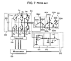
- FIG. 7 shows a structure of the conventional inverter
- FIG. 8 shows characteristics of torque vs. rotational speed of the conventional inverter. Specifically, it shows the characteristics of wide-angle control.
- FIG. 8 tells that the maximum rotational speed increases at a wider conduction angle provided when the torque is kept at a constant level.
- FIG. 9 shows timing charts of the signal waveforms of respective sections of the conventional inverter controller.
- the timing charts also indicate the processes of the respective sections and the characteristics at conduction angle of 150 degrees in electrical angles.
- three pairs of switching transistors connected in series i.e. Tru and Trx, Try and Try, Trw and Trz are coupled between the terminals of DC power supply 001 , thereby forming inverter circuit 002 .
- Brushless DC motor 003 is formed of stator 003 A and rotor 003 B.
- Stator 003 A is formed of four poles and distributed windings.
- Rotor 003 B is an interior magnet type where permanent magnets 003 N and 003 S are embedded.
- connection points of respective pairs of the switching transistors are coupled to brushless DC motor 003 at respective terminals of stator windings 003 U, 003 V, and 003 W of respective phases, forming a “wye” connection.
- the connection points of respective pairs of the switching transistors are also coupled to respective resistors 004 U, 004 V, and 004 W forming a “wye” connection.
- Reflux diodes Du, Dx, Dv, Dy, Dw, and Dz are coupled between the collector and the emitter of respective switching transistors Tru, Trx, Trv, Try, Trw, and Trz, for a protection purpose.
- Pole-position sensing circuit 010 is formed of differential amplifier 011 , integrator 012 , and zero-crossing comparator 013 .
- a voltage at neutral point 003 D of stator windings 003 U, 003 V, and 003 W coupled together in the wye connection is supplied to an inverting input terminal of amplifier 011 B via resistor 011 A.
- a voltage at neutral point 004 D of resistors 004 U, 004 V, and 004 W coupled together in the wye connection is supplied directly to non-inverting input terminal of amplifier 011 B.
- Resistor 011 C is coupled between an output terminal and the non-inverting input terminal of amplifier 011 B. Differential amplifier 011 is thus formed.
- An output signal from the output terminal of differential amplifier 011 is supplied to integrator 012 formed of resistor 012 A and capacitor 012 B coupled together in series.
- An output signal from integrator 012 i.e. a voltage at a connection point between resistor 012 A and capacitor 012 B
- a voltage at neutral point 003 D is supplied to an inverting input terminal of zero-crossing comparator 013 .
- An output terminal of zero-crossing comparator 013 outputs a pole-position sensing signal.
- Pole-position sensing circuit 010 which senses a pole position of rotor 003 B of brushless DC motor 003 .
- Pole-position sensing circuit 010 outputs the pole-position sensing signal to microprocessor 020 .
- Microprocessor 020 then corrects the phases of the supplied pole-position sensing signal in order to measure a cycle, and set a phase advance angle as well as a conduction angle.
- Microprocessor 020 calculates a timer counting value per cycle of an electric angle for determining a commutation signal of respective switching transistors Tru, Trx, Trv, Try, Trw, and Trz.
- Microprocessor 020 outputs a voltage instruction based on a rotational speed instruction, and performs pulse width modulation (PWM) to the voltage instruction.
- Microprocessor 020 controls a duty ratio, i.e. a ratio of ON vs. OFF of a PWM signal, based on a difference between the rotational speed instruction and an actual rotational speed, and outputs PWM signals for the three phases.
- Microprocessor 020 increases the duty ratio when the actual rotational speed is smaller than the rotational speed instruction, and reduces the duty ratio when the actual rotational speed is greater than the rotational speed instruction.
- the PWM signal is supplied to driving circuit 030 .
- Driving circuit 030 outputs driving signals to respective base terminals of switching transistors Tru, Trx, Trv, Try, Trw, and Trz.
- induction voltages Eu, Ev, and Ew of phases U, V and W of brushless DC motor 003 vary while the respective phases shift by 120 degrees from each other.
- a differential amplifier output signal indicates a signal output from differential amplifier 011 .
- a signal supplied from integrator 012 forms an integral waveform shaped by integrator 012 .
- a supply of the integral waveform to zero-crossing comparator 013 prompts an output signal from zero-crossing comparator 013 to rise and then fall at the zero-crossing point of the integral waveform. This excitation switching signal is output as the pole-position sensing signal.
- phase correction timer G 1 The rise and fall of the excitation switching signal prompt phase correction timer G 1 to start, and the start of timer G 1 prompts second phase correction timer G 2 to start.
- Both of timers G 1 and G 2 advance inverter mode N, i.e. a commutation pattern, by one step.
- a conduction timing of phase U can be calculated based on the induction voltage waveform of phase W, and an amount of phase advance of the inverter can be controlled by phase-correction timer G 1 .
- a phase advance angle is set at 60 degrees when conduction angle is 150 degrees in electric angles.
- Phase correction timer G 1 thus counts a value corresponding to 45 degrees
- second phase correction timer G 2 counts a value corresponding to 30 degrees in electric angles.
- the ON-OFF states of switching transistors Tru, Trx, Trv, Try, Trw, and Trz are controlled as shown in FIG. 9 in response to the respective inverter modes.
- brushless DC motor 003 can be driven in a state where a conduction period is set between 120 degrees and 180 degrees, and a phase of inverter voltage can be advanced with respect to that of the induction voltage of the motor.
- the rotation of rotor 003 B generates an induction voltage at stator windings 003 U, 003 V, 003 W, and the induction voltage can be sensed through the foregoing conventional structure.
- This induction voltage is shifted its phase by integrator 012 having a delay of 90 degrees, thereby sensing a position sensing signal corresponding to a magnetic pole of rotor 003 B. Based on this position sensing signal, conduction timings to stator windings 003 U, 003 V, 003 W are determined.
- Use of such integrator 012 as having a phase-delay of 90 degrees lowers the responsiveness to an abrupt acceleration or deceleration.
- FIG. 10 shows a structure of another conventional inverter controller
- FIG. 11 shows timing charts of the signal waveforms of respective sections of the conventional inverter controller. The timing charts also indicate the processes of the respective sections.
- resistors 101 and 102 are coupled in series between bus 103 and bus 104 , and their common connection point, i.e. sensing terminal ON, supplies voltage VN of a virtual neutral point.
- Voltage VN is a half of the voltage of DC power supply 001 , and the voltage of DC power supply 001 corresponds to a voltage of the neutral point of stator windings 105 U, 105 V, and 105 W.
- Respective non-inverting input terminals (+) of comparator 106 A, 106 B, and 106 C are coupled to output terminals OU, OV, and OW via resistors 107 , 108 , and 109 , respectively.
- Respective inverting input terminals ( ⁇ ) of the comparators are coupled to sensing terminal ON.
- Respective output terminals of comparators 106 A, 106 B, and 106 C are coupled to microprocessor 110 , having a logic circuit therein, at its input terminals I 1 , I 2 , and I 3 .
- Outputs from output terminals 01 through 06 of microprocessor 110 drive switching transistors Tru, Trx, Trv, Try, Trw, and Trz via driving circuit 120 .
- Brushless DC motor 105 includes four poles and distributed windings.
- Rotor 105 A forms a structure of surface mounted magnet, i.e. permanent magnets 105 N and 105 S are mounted to the surface of rotor 105 A.
- Motor 105 is thus set in a state where conduction angle is set at 120 degrees and phase advance angle is set at 0 degree in electric angles.
- Terminal voltage Vu, terminal voltage Vv, and terminal voltage Vw indicate respectively the voltages across stator windings 105 U, 105 V, and 105 W during a regular operation of motor 105 .
- inverter circuit 140 supplies voltages Vua, Vva, and Vwa, and stator windings 105 U, 105 V, and 105 W generate induction voltages Vub, Vvb, and Vwb.
- Output signals PSu, PSv, PSw from the comparators indicate the results of comparison done by comparators 106 A, 106 B, 106 C between terminal voltages Vu, Vv, Vw and voltage VN at the virtual neutral point.
- output signals PSu, PSv, PSw are formed of signals PSua, PSva, PSwa which indicate a positive-negative and a phase of each one of induction voltages Vub, Vvb, Vwb, and output signals PSub, PSvb, PSwb corresponding to spike voltages Vuc, Vvc, Vwc.
- Microprocessor 110 recognizes six modes, A, B, C, D, E, and F as shown in the mode column based on the status of signals PSu, PSv, PSw output from the comparators, and then it outputs driving signals DSu through DSz with a delay of 30 degrees in electric angles from the instant of variation in levels of output signals PSu, PSv, PSw.
- Respective time T of each mode A through F indicates 60 degrees, and a half of the time of each mode A through F, i.e. T/2, indicates a delay time corresponding to 30 degrees in electric angles.
- Microprocessor 110 thus senses the rotational position of rotor 105 A of motor 105 based on the induction voltages generated at stator windings 105 U, 105 V, 105 W in response to the rotation of rotor 105 A. It also determines driving signals for the conduction to stator windings 105 U, 105 V, 105 W, depending on the conduction mode and the timing, by detecting the variable time T of the induction voltages, and then supplies electricity to stator windings 105 U, 105 V, and 105 W.
- the foregoing structure thus differs from the conventional inverter controller disclosed in Patent citation 1, and since it needs no filter circuit, it can detect an induction voltage with higher sensitivity. As a result, starting characteristic can be improved, and the motor can be driven at a lower rotational speed. On top of that, since no filter circuit having a delay of 90 degrees is used, the motor can be controlled with a delay of as small as 30 degrees by combining first timer 122 and second timer 123 . The responsiveness to an abrupt acceleration or deceleration can be thus improved.
- FIG. 12 shows the out-of-synchronous characteristics of the voltages and the conduction angles of the inverter controller shown in FIG. 10 .
- FIG. 12 shows, in the case of a sharp fall of the voltage, a resistance to the out-of-synchronous decreases at a greater conduction angle. Characteristics similar to this one can be also observed when the voltage sharply rises.
- Patent citation 1 proposes magnetic-pole-position sensing circuit 010 operable within a period of 180 degrees in electric angles.
- circuit 010 employs a filter, a delay of 90 degrees in electric angles occurs, which causes a lower responsiveness to a variation in rotational speed such as an abrupt change in load. As a result, the motor sometimes falls in out-of-synchronous and halts its work.
- Patent citation 2 proposes a position sensing circuit free from a delay of 90 degrees in electric angles.
- this structure sometimes cannot sense the pole-position during a rotational variation, such as an abrupt change in load, and thus the motor may fall in out-of-synchronous.
- Such a phenomenon occurs in the following cases: (1) when wide-angle control which widens a conduction angle to over 120 degrees is carried out, (2) when phase-advance-angle control is carried out, this control method advances a voltage phase of the inverter with respect to a phase of the induction voltage of the motor, (3) when a width of the spike voltage is widened in order to obtain a higher efficiency by increasing an inductance through a greater number of turns of stator windings 105 U, 105 V, 150 W. These cases incur a shorter position sensible period.
- the position sensible period decreases to as small as 2 ⁇ 3 mechanical angles comparing with the case of using four poles. Therefore, the foregoing wide-angle control, the phase-advance-angle control, the increase in the number of turns, or the increase in the number of poles for incurring the shorter mechanical position sensible range, shortens the pole-position sensible period.
- an occurrence of a variation in load, an instantaneous power interruption, or a variation in voltage will accompany an abrupt variation in rotation, so that the inverter controller fails to sense the pole position and the motor falls in the out-of-synchronous.
- the present invention provides a reliable inverter controller which changes instantaneously a conduction angle in response to a change in voltage of a DC voltage section, thereby preventing a brushless DC motor from falling in out-of-synchronous and stopping its work due to an instantaneous power interruption or an abrupt change in voltage.
- the present invention also provides motor driving devices, electric compressors, and electric home appliances using the inverter controller.
- the inverter controller of the present invention drives a brushless DC motor, of which rotor includes permanent magnets.
- the inverter controller has an inverter circuit, a position sensing circuit, a DC voltage sensor, and a conduction angle controller. The inverter circuit is coupled to and drives the brushless DC motor.
- the position sensing circuit senses a position of the rotor with respect to a stator from an induction voltage of the brushless DC motor.
- the DC voltage sensor senses a voltage supplied to the inverter circuit.
- the conduction angle controller changes a conduction angle of the inverter circuit in response to a rate of change in the voltage supplied from the DC power supply within the range lower than 180 degrees in electric angles.
- FIG. 1 [ FIG. 1 ]
- FIG. 1 shows a structure of an inverter controller in accordance with an embodiment of the present invention.
- FIG. 2 [ FIG. 2 ]
- FIG. 2 is a timing chart showing waveforms of respective sections in the inverter controller shown in FIG. 1 and the processes done by the respective sections.
- FIG. 3 [ FIG. 3 ]
- FIG. 3 shows characteristics indicating the relation between conduction angles and variations in a power supply voltage of the inverter controller shown in FIG. 1 .
- FIG. 4 is a timing chart showing operation of the inverter controller shown in FIG. 1 when a voltage changes therein.
- FIG. 5 [ FIG. 5 ]
- FIG. 5 is a block diagram of an electric compressor that employs the inverter controller shown in FIG. 1 .
- FIG. 6 is schematically a sectional view of a refrigerator as an example of electric home appliances that employ the compressor shown in FIG. 5 .
- FIG. 7 shows a structure of a conventional inverter controller.
- FIG. 8 shows characteristics of torque vs. rotational speed of the inverter controller shown in FIG. 7 .
- FIG. 9 is a timing chart showing waveforms of respective sections of the inverter controller shown in FIG. 7 and the processes done by the respective sections.
- FIG. 10 shows a structure of another conventional inverter controller.
- FIG. 11 is a timing chart showing waveforms of respective sections of the inverter controller shown in FIG. 10 and the processes done by the respective sections.
- FIG. 12 shows characteristics of out-of-synchronous caused by the relation between voltages and conduction angles of the inverter controller shown in FIG. 10 .
- FIG. 1 shows a structure of an inverter controller in accordance with this embodiment of the present invention.
- FIG. 2 is a timing chart showing waveforms of respective sections in the inverter controller and timing the processes done by the respective sections.
- FIG. 3 shows characteristics indicating the relation between conduction angles and voltage variations in a power supply of the inverter controller.
- FIG. 4 is a timing chart showing operation of the inverter controller when a voltage changes in the inverter controller.
- inverter controller 200 is coupled to commercial AC power supply 201 and brushless DC motor (hereinafter simply referred to as “motor”) 204 , and drives motor 204 .
- Inverter controller 200 and motor 204 thus form motor driving device 300 .
- Motor 204 includes rotor 204 B provided with permanent magnets 204 C through 240 H.
- Inverter controller 200 includes inverter circuit 205 , position sensing circuit 207 , DC voltage sensor 209 , and microprocessor 208 having conduction angle controller 217 .
- Motor 204 has six poles and concentrated windings on salient poles, and is formed of rotor 204 B and stator 204 A having three-phase windings.
- Stator 204 A has six poles and nine slots, and the number of turns of respective stator windings 204 U, 204 V, 204 W is 189 .
- Rotor 204 B includes permanent magnets 204 C through 204 H therein, and forms an interior-magnets structure which generates reluctance torque.
- Inverter controller 200 further has rectifier 203 , driving circuit 206 .
- Rectifier 203 converts commercial AC power supply 201 into a DC power supply, and driving circuit 206 drives inverter circuit 205 .
- Inverter circuit 205 is coupled to and drives motor 204 , and is formed of six switching transistors Tru, Trx, Trv, Try, Trw, and Trz coupled together forming a three-phase bridge, and reflux diodes Du, Dx, Dv, Dy, Dw, and Dz respectively coupled in parallel with the switching transistors.
- Position sensing circuit 207 senses a position of rotor 204 B with respect to stator 204 A from an induction voltage of motor 204 , and is formed of comparators (not shown) and the like. Circuit 207 compares a terminal voltage signal based on the induction voltage of motor 204 with a reference voltage by the comparators, thereby outputting a position signal of rotor 204 B.
- the structure of circuit 207 is similar to the structure formed of comparators 106 A, 106 B, 106 C shown in FIG. 10 .
- DC voltage sensor 209 senses a DC power voltage supplied to inverter circuit 205 .
- sensor 209 senses a voltage converted into a DC form by rectifier 203 , and forms a voltage divider circuit using resistors.
- Sensor 209 outputs the sensed voltage in the form of analog value to microprocessor 208 , and it includes a CR filter circuit for reducing noises.
- Microprocessor 208 is shown with the block diagrams including respective functions that control inverter circuit 205 . These function blocks can be formed of an exclusive circuit, or formed of software built in hardware. To be more specific, microprocessor 208 has rotational speed sensor 210 , commutation controller 211 , duty setting section 212 , PWM controller 213 , drive controller 214 , and carrier outputting section 215 .
- Microprocessor 208 further has conduction angle controller 217 which changes a conduction angle in response to a rate of change in the DC power voltage, and conduction angle setting section 218 which sets the maximum value of the conduction angle.
- conduction angle controller 217 changes the conduction angle of inverter circuit 205 within the range over 0 degree to less than 180 degrees in electric angles in response to the rate of change in the DC power voltage.
- Microprocessor 208 includes timer 219 for finding a change in voltage per unit time, i.e. the rate of change in the DC power voltage.
- Commutation controller 211 calculates a timing of the commutation based on a position signal supplied from position sensing circuit 207 , and produces commutation signals for the switching transistors Tru, Trx, Trv, Try, Trw, and Trz.
- Rotational speed sensor 210 counts position signals for a certain period, or measures pulse intervals, thereby calculating the rotational speed of motor 204 .
- Duty setting section 212 makes add-subtract calculations of a duty ratio by using a deviation between the rotational speed obtained by rotational speed sensor 210 and an instructed rotational speed, and supplies the duty ratio to PWM controller 213 .
- a greater duty ratio is supplied PWM controller 213 when an actual rotational speed is lower than the instructed rotational speed, and a smaller duty ratio is supplied when the actual rotational speed is higher than the instructed rotational speed.
- Carrier outputting section 215 sets a carrier frequency that switches the switching transistors Tru, Trx, Trv, Try, Trw, and Trz.
- the carrier frequency is set between 3 kHz and 10 kHz.
- PWM controller 213 outputs a PWM modulated signal based on the carrier frequency set by carrier outputting section 215 and the duty ratio set by duty setting section 212 .
- Conduction angle controller 217 calculates a rate of change in voltage per unit time with timer 219 based on the DC voltage sensed by DC voltage sensor 209 , and controls a conduction angle in inverter circuit 205 to decrease at a greater rate of change in the voltage.
- conduction angle controller 217 reads a voltage sensed by DC voltage sensor 209 at a sampling cycle, i.e. every 5 ms, and calculates the rate of change in the DC power voltage. When a little change in the voltages is produced and thus controller 217 determines that no variation is found in the rate of change, controller 217 increases the conduction angle step by step.
- Drive controller 214 compounds a commutation signal, a PWM modulated signal, a conduction angle, and a phase advance angle, thereby producing a driving signal, which turns on or off the switching transistors, Tru, Trx, Trv, Try, Trw, and Trz, and outputs this driving signal to driving circuit 206 .
- Driving circuit 206 then turns on or off the switching transistors, Tru, Trx, Trv, Try, Trw, and Trz, based on the driving signal, thereby driving motor 204 .
- Inverter controller 200 controls motor 204 with the conduction angle set at 150 degrees and the phase advance angle set at 15 degrees in electric angles.
- Conduction angle setting section 218 sets the maximum conduction angle at 150 degrees, and minimum conduction angle at 120 degrees.
- any one of reflux diodes Du, Dx, Dv, Dy, Dw, and Dz of inverter circuit 205 becomes conductive at a switching event of the commutation, thereby producing pulse-like spike voltages Vuc, Vvc, Vwc.
- terminal voltages Vu, Vv, Vw shape waveforms which are combined by supplied voltages Vua, Vva, Vwa, induction voltages Vub, Vvb, Vwb, and spike voltages Vuc, Vvc, Vwc.
- the comparators compare terminal voltages Vu, Vv, Vw with voltage VN at a virtual neutral point, i.e. a half of the voltage produced by the DC power supply, and outputs signals PSu, PSv, PSw.
- this embodiment of the present invention allows DC voltage sensor 209 to sense a change in the DC power voltage, and allows conduction angle controller 217 to calculate a rate of change in the DC power voltage every 5 ms, i.e. the cycle of timer 219 , thereby determining a conduction angle.
- Conduction angle controller 217 decreases the conduction angle as the change in the DC power voltage becomes greater, and also decreases the conduction angle as a variation time becomes longer. The conduction angle is thus changed in response to the rate of change in the DC voltage, so that motor 204 can be more stably.
- the rate of change in the DC power voltage is 100V/second, 200V/second, or 300V/second, and then the DC power voltage stays stable at reference voltage E 0 and at conduction angle 150 degrees until reference time reaches “t 0 ”.
- controller 217 From time “t 0 ”, the DC power voltage starts varying. Since conduction angle controller 217 senses the DC power voltage with timer 219 every 5 ms, controller 217 can calculate the rate of change in the voltages at point “t 1 ”, “t 2 ”, “t 3 ”, and onward at intervals of every 5 ms.
- the minimum resolution of the conduction angle is set at 3.75 degrees in electrical angles, so that when the rate of change is 100V/second, the conduction angle decreases by 3.75 degrees every 10 ms, and in the case of 200V/second, it decreases by 3.75 degrees every 5 ms, and in the case of 300V/second, it decreases by 11.25 degrees in 10 ms.
- inverter controller 200 during a variation in voltages, e.g. during an instantaneous power interruption, is described with reference to FIG. 4 .
- motor 204 When motor 204 is in an initial state, motor 204 is under a heavy load and rotates at a high rotational speed.
- conduction angle controller 217 reduces the conduction angle from 150 degrees to 127.5 degrees in response to the rate of change in the DC power voltage. The reduction in the conduction angle allows enlarging the position sensible period, so that position sensing circuit 207 will not lose the pole position of the rotor in the conduction period. As a result, the out-of-synchronous due to a change in voltages can be prevented.
- Step 2 conduction angle controller 217 widens the conduction angle step by step (every 100 ms), and then after a lapse of 500 ms, the conduction angle increases from 127.5 degrees to 142.5 degrees. In this case, the output becomes low due to a low voltage, so that a wider conduction angle is needed for increasing the output. Conduction angle controller 217 thus tries to increase the angle to the maximum angle, i.e. 150 degrees. In other words, when the DC power voltage is stable, conduction angle controller 217 increases the conduction angle step by step to the value set by conduction angle setting section 218 . In such a case, since no variation in the rotation occurs, wide-angle operation is achievable, and the conduction angle can be restored to the given value when the voltage becomes stable. As a result, motor 204 can work again at a high rotational speed and produce again large torque.
- conduction angle controller 217 changes the conduction angle from 142.5 degrees to 120 degrees. In other words, when the DC power voltage rises at a given rate of change or over that given rate, controller 217 reduces the conduction angle in response to the rate of change in the DC power voltage. This is similar to the case when the DC power voltage sharply falls.
- the position sensible period thus can be enlarged, so that position sensing circuit 207 will not lose the pole position of the rotor in the spike voltage. As a result, motor 204 is prevented from falling in the out-of-synchronous caused by the change in rotation due to an increase in voltage.
- conduction angle controller 217 controls the conduction angle to decrease.
- conduction angle controller 217 maintains the conduction angle at 120 degrees, i.e. the minimum set value.
- conduction angle controller 217 increases the conduction angle to the given value, i.e. 150 degrees (maximum set value). However, since the high voltage allows outputting high power, the maximum set value can be as small as 120 degrees.
- the maximum conduction angle can be set in response to the duty ratio, rotational speed, and DC power voltage.
- rotor 204 B employs interior permanent magnets 204 C through 204 H, and has salient-pole properties, so that motor 204 can produce reluctance torque.
- a phase advance control is carried out in order to efficiently use the reluctance torque; however, use of this phase advance control together with the wide-angle control will further reduce the position sensible period.
- This embodiment yet proves that the phase advance control in addition to the wide-angle control will reduce events of the out-of-synchronous caused by changes in voltage, so that the resistance to the instantaneous power interruption can be increased.
- stator 204 A having a greater number of turns will increase the inductance, thereby widening the width of the spike voltage, so that the position sensible period decreases. To be more specific, in the case of over 160 turns of the stator winding, this phenomenon appears conspicuously. However, this embodiment prevents such a motor from falling in the out-of-synchronous caused by changes in voltage, so that the resistance to the instantaneous power interruption can be increased.
- Motor 204 having six poles or more than six poles is obliged to encounter a difficulty of sensing a rotor position comparing with a conventional motor having four poles, because the increase in the number of poles reduces the position sensible period due to an issue of mechanical angle.
- this embodiment prevents motor 204 having six poles or more than six poles from falling in the out-of-synchronous caused by changes in voltage, so that the resistance to the instantaneous power interruption can be increased.
- the conduction angles changes from 150 degrees to 120 degrees step by step through nine steps; however, the rate of change in the DC power voltage and the conduction angle can be changed linearly, and a sampling cycle of the DC power voltage can be set at any value.
- use of the conduction angle less than 120 degrees will make the system more resistible to the changes in power voltage or the instantaneous power interruption.
- inverter controller 200 and motor 204 form motor driving device 300
- motor driving device 300 and compressing section 400 form electric compressor 500
- Motor driving device 300 drives compressing section 400 , which is a driven body.
- Compressor 500 thus can prevent motor 204 from falling in the out-of-synchronous caused by changes in voltage, and it also can make motor 204 more resistible to the instantaneous power interruption, thereby increasing the reliability.
- electric home appliances such as refrigerators
- motor driving device 300 can be used for driving a motor of washing machines. In the later case, a pulsator or a rotary drum is driven by motor driving device 300 .
- the use of motor driving device 300 in electric home appliances discussed above assures excellent operation of the appliances.
- the inverter controller of the present invention can sense a magnetic pole position of the rotor without losing the pole positions of the rotor even if a change in the power voltage occurs.
- the inverter controller is useful in electric home appliances such as air-conditioners, refrigerators, and washing machines and electric vehicles encountering changes in the power voltage. It is also useful in the regions where changes in the power voltage often occur.
Landscapes
- Engineering & Computer Science (AREA)
- Power Engineering (AREA)
- Control Of Motors That Do Not Use Commutators (AREA)
- Control Of Ac Motors In General (AREA)
- Control Of Multiple Motors (AREA)
Abstract
Description
- International Publication Pamphlet No. 95/27328
[Patent Citation 2] - Japanese Patent Unexamined Publication No. H01-8890
Claims (12)
Applications Claiming Priority (3)
| Application Number | Priority Date | Filing Date | Title |
|---|---|---|---|
| JP2007-318150 | 2007-12-10 | ||
| JP2007318150 | 2007-12-10 | ||
| PCT/JP2008/003549 WO2009075071A2 (en) | 2007-12-10 | 2008-12-02 | Inverter controller, and motor driving device, electric compressor and electric home appliance using the inverter controller |
Publications (2)
| Publication Number | Publication Date |
|---|---|
| US20100237809A1 US20100237809A1 (en) | 2010-09-23 |
| US8212504B2 true US8212504B2 (en) | 2012-07-03 |
Family
ID=40261195
Family Applications (1)
| Application Number | Title | Priority Date | Filing Date |
|---|---|---|---|
| US12/594,261 Active 2029-06-24 US8212504B2 (en) | 2007-12-10 | 2008-12-02 | Conduction angle control of brushless motor |
Country Status (7)
| Country | Link |
|---|---|
| US (1) | US8212504B2 (en) |
| EP (1) | EP2115866B1 (en) |
| JP (2) | JP2010541517A (en) |
| CN (1) | CN101821939B (en) |
| AT (1) | ATE508526T1 (en) |
| DE (1) | DE602008006676D1 (en) |
| WO (1) | WO2009075071A2 (en) |
Cited By (12)
| Publication number | Priority date | Publication date | Assignee | Title |
|---|---|---|---|---|
| US20110037423A1 (en) * | 2008-04-18 | 2011-02-17 | Panasonic Corporation | Inverter controller, compressor, and electric home appliance |
| US20110057593A1 (en) * | 2008-05-08 | 2011-03-10 | Connel Brett Williams | Position Sensorless Motor Control |
| US20130134918A1 (en) * | 2010-06-22 | 2013-05-30 | Aeristech Control Technologies Limited | Controller |
| USRE45897E1 (en) | 2008-04-14 | 2016-02-23 | Stanley Black & Decker, Inc. | Battery management system for a cordless tool |
| US20160075004A1 (en) * | 2014-09-12 | 2016-03-17 | Panasonic Intellectual Property Management Co., Ltd. | Rotary impact tool |
| US9406915B2 (en) | 2014-05-18 | 2016-08-02 | Black & Decker, Inc. | Power tool system |
| US9893384B2 (en) | 2014-05-18 | 2018-02-13 | Black & Decker Inc. | Transport system for convertible battery pack |
| US10243491B2 (en) | 2014-12-18 | 2019-03-26 | Black & Decker Inc. | Control scheme to increase power output of a power tool using conduction band and advance angle |
| US11171586B2 (en) | 2019-04-25 | 2021-11-09 | Black & Decker Inc. | Low-speed sensorless brushless motor control in a power tool |
| US11211664B2 (en) | 2016-12-23 | 2021-12-28 | Black & Decker Inc. | Cordless power tool system |
| US11329597B2 (en) | 2015-11-02 | 2022-05-10 | Black & Decker Inc. | Reducing noise and lowering harmonics in power tools using conduction band control schemes |
| US11569765B2 (en) | 2019-10-11 | 2023-01-31 | Black & Decker Inc. | Power tool receiving different capacity battery packs |
Families Citing this family (21)
| Publication number | Priority date | Publication date | Assignee | Title |
|---|---|---|---|---|
| US8248019B2 (en) * | 2007-06-05 | 2012-08-21 | Edwards Japan Limited | Brushless motor |
| CN102362427B (en) * | 2009-03-24 | 2014-11-26 | 株式会社Ihi | Device and method for power-saving driving of device having same load pattern |
| JP5558125B2 (en) * | 2010-01-28 | 2014-07-23 | 株式会社東芝 | Motor control device and control method |
| JP5491346B2 (en) * | 2010-10-13 | 2014-05-14 | 株式会社マキタ | Power tools and programs |
| JP5530905B2 (en) * | 2010-11-19 | 2014-06-25 | 日立アプライアンス株式会社 | Motor controller, air conditioner |
| US20120181963A1 (en) * | 2011-01-19 | 2012-07-19 | Texas Instruments Incorporated | Initial position detection for a sensorless, brushless dc motor |
| ITBO20110340A1 (en) * | 2011-06-13 | 2012-12-14 | Spal Automotive Srl | ELECTRIC DRIVE |
| ITTO20120311A1 (en) * | 2012-04-10 | 2013-10-11 | Gate Srl | CIRCUIT TEST DEVICE FOR A THREE-PHASE BRUSHLESS MOTOR |
| GB2507304B (en) * | 2012-10-25 | 2020-02-12 | Eaton Intelligent Power Ltd | A tracking circuit and method for tracking an orientation of a rotor of a motor during a loss of source power to a motor drive |
| JP6085488B2 (en) * | 2013-01-28 | 2017-02-22 | 株式会社マキタ | Electric tool |
| US8941961B2 (en) * | 2013-03-14 | 2015-01-27 | Boulder Wind Power, Inc. | Methods and apparatus for protection in a multi-phase machine |
| CN105553343A (en) * | 2015-02-06 | 2016-05-04 | 长沙启科电子有限公司 | Capacitor-free direct-current brushless driving controller |
| CN104716876A (en) * | 2015-04-10 | 2015-06-17 | 苏州百微成智能科技有限公司 | Novel brushless motor control method |
| CN104767435B (en) * | 2015-04-27 | 2017-03-08 | 山东大学 | Non sensor brushless motor commutation phase place real-time correction method based on neutral point voltage |
| EP3444942B1 (en) * | 2016-04-13 | 2021-03-10 | Hitachi Industrial Equipment Systems Co., Ltd. | Electric motor system |
| CN109302115B (en) * | 2017-07-25 | 2020-10-02 | 郑州宇通客车股份有限公司 | New energy automobile motor electrical angle correction method |
| CN109873578B (en) * | 2017-12-04 | 2023-03-24 | 南京泉峰科技有限公司 | Electric tool and control method thereof |
| JP6972305B2 (en) * | 2018-03-28 | 2021-11-24 | 新電元工業株式会社 | Drive device, drive method, drive program and electric vehicle |
| US11561247B2 (en) * | 2021-04-19 | 2023-01-24 | Infineon Technologies Ag | Voltage monitor using switching signal for motor |
| CN221842456U (en) * | 2021-04-26 | 2024-10-15 | 米沃奇电动工具公司 | Power Tools |
| CN115882578A (en) * | 2021-09-29 | 2023-03-31 | 硕天科技股份有限公司 | Uninterruptible power system and power supply conversion circuit thereof |
Citations (11)
| Publication number | Priority date | Publication date | Assignee | Title |
|---|---|---|---|---|
| JPS648890A (en) | 1987-06-29 | 1989-01-12 | Toshiba Corp | Controller for brushless motor |
| WO1995027328A1 (en) | 1994-03-31 | 1995-10-12 | Daikin Industries, Ltd. | Method of controlling driving of brushless dc motor, and apparatus therefor, and electric machinery and apparatus used therefor |
| US20020030462A1 (en) | 2000-07-14 | 2002-03-14 | Hideo Matsushiro | Apparatus and method for driving a brushless motor |
| US20020140395A1 (en) | 2001-03-29 | 2002-10-03 | Matsushita Electric Industrial Co., Ltd. | Brushless motor control method and controller |
| JP2006174643A (en) | 2004-12-17 | 2006-06-29 | Matsushita Electric Ind Co Ltd | Motor controller |
| JP2006174665A (en) | 2004-12-20 | 2006-06-29 | Matsushita Electric Ind Co Ltd | Motor controller |
| JP2006180651A (en) | 2004-12-24 | 2006-07-06 | Matsushita Electric Ind Co Ltd | Motor controller |
| JP2007104861A (en) | 2005-10-07 | 2007-04-19 | Matsushita Electric Ind Co Ltd | Motor controller |
| JP2007209153A (en) | 2006-02-03 | 2007-08-16 | Matsushita Electric Ind Co Ltd | Motor controller |
| JP2007221867A (en) | 2006-02-15 | 2007-08-30 | Matsushita Electric Ind Co Ltd | Motor controller |
| US7755308B2 (en) * | 2007-06-29 | 2010-07-13 | Caterpillar Inc | Conduction angle control of a switched reluctance generator |
Family Cites Families (8)
| Publication number | Priority date | Publication date | Assignee | Title |
|---|---|---|---|---|
| JPH0727328A (en) | 1993-07-15 | 1995-01-27 | Osada Res Inst Ltd | Dental gas burner |
| CN2478280Y (en) * | 2001-04-05 | 2002-02-20 | 张相军 | Rotor pole position detector of brushless d.c. motor |
| JP2003259678A (en) * | 2002-03-05 | 2003-09-12 | Matsushita Electric Ind Co Ltd | Controller of dc brushless motor |
| CN100448158C (en) * | 2003-04-30 | 2008-12-31 | 松下电器产业株式会社 | Motor driving apparatus |
| JP2005176529A (en) * | 2003-12-12 | 2005-06-30 | Asmo Co Ltd | Controller for brushless motor and fan motor device |
| JP2006025565A (en) * | 2004-07-09 | 2006-01-26 | Matsushita Electric Ind Co Ltd | Inverter circuit and compressor |
| KR20060075262A (en) * | 2004-12-28 | 2006-07-04 | 삼성전자주식회사 | Phase change method of BLC motor |
| JP2007014115A (en) * | 2005-06-30 | 2007-01-18 | Matsushita Electric Ind Co Ltd | Motor control device |
-
2008
- 2008-12-02 US US12/594,261 patent/US8212504B2/en active Active
- 2008-12-02 CN CN2008801107687A patent/CN101821939B/en active Active
- 2008-12-02 JP JP2009543299A patent/JP2010541517A/en active Pending
- 2008-12-02 DE DE602008006676T patent/DE602008006676D1/en active Active
- 2008-12-02 EP EP08859612A patent/EP2115866B1/en active Active
- 2008-12-02 AT AT08859612T patent/ATE508526T1/en not_active IP Right Cessation
- 2008-12-02 WO PCT/JP2008/003549 patent/WO2009075071A2/en active Application Filing
-
2013
- 2013-04-25 JP JP2013092330A patent/JP2013179833A/en active Pending
Patent Citations (13)
| Publication number | Priority date | Publication date | Assignee | Title |
|---|---|---|---|---|
| JPS648890A (en) | 1987-06-29 | 1989-01-12 | Toshiba Corp | Controller for brushless motor |
| WO1995027328A1 (en) | 1994-03-31 | 1995-10-12 | Daikin Industries, Ltd. | Method of controlling driving of brushless dc motor, and apparatus therefor, and electric machinery and apparatus used therefor |
| US5804939A (en) | 1994-03-31 | 1998-09-08 | Yamai; Hiroyuki | Brushless D.C. motor driving and controlling method and apparatus therefor and electrical equipment |
| US20020030462A1 (en) | 2000-07-14 | 2002-03-14 | Hideo Matsushiro | Apparatus and method for driving a brushless motor |
| US6512341B2 (en) * | 2000-07-14 | 2003-01-28 | Matsushita Electric Industrial Co., Ltd. | Apparatus and method for driving a brushless motor |
| US20020140395A1 (en) | 2001-03-29 | 2002-10-03 | Matsushita Electric Industrial Co., Ltd. | Brushless motor control method and controller |
| JP2006174643A (en) | 2004-12-17 | 2006-06-29 | Matsushita Electric Ind Co Ltd | Motor controller |
| JP2006174665A (en) | 2004-12-20 | 2006-06-29 | Matsushita Electric Ind Co Ltd | Motor controller |
| JP2006180651A (en) | 2004-12-24 | 2006-07-06 | Matsushita Electric Ind Co Ltd | Motor controller |
| JP2007104861A (en) | 2005-10-07 | 2007-04-19 | Matsushita Electric Ind Co Ltd | Motor controller |
| JP2007209153A (en) | 2006-02-03 | 2007-08-16 | Matsushita Electric Ind Co Ltd | Motor controller |
| JP2007221867A (en) | 2006-02-15 | 2007-08-30 | Matsushita Electric Ind Co Ltd | Motor controller |
| US7755308B2 (en) * | 2007-06-29 | 2010-07-13 | Caterpillar Inc | Conduction angle control of a switched reluctance generator |
Non-Patent Citations (2)
| Title |
|---|
| European Office Action for Application No. 08859612.7, May 25, 2010, Panasonic Corporation. |
| International Search Report for International Application No. PCT/JP2008/003549, Jul. 15, 2009, Panasonic Corporation. |
Cited By (34)
| Publication number | Priority date | Publication date | Assignee | Title |
|---|---|---|---|---|
| USRE45897E1 (en) | 2008-04-14 | 2016-02-23 | Stanley Black & Decker, Inc. | Battery management system for a cordless tool |
| US20110037423A1 (en) * | 2008-04-18 | 2011-02-17 | Panasonic Corporation | Inverter controller, compressor, and electric home appliance |
| US20110057593A1 (en) * | 2008-05-08 | 2011-03-10 | Connel Brett Williams | Position Sensorless Motor Control |
| US8502488B2 (en) * | 2008-05-08 | 2013-08-06 | Trw Automotive Us Llc | Position sensorless motor control |
| US20130134918A1 (en) * | 2010-06-22 | 2013-05-30 | Aeristech Control Technologies Limited | Controller |
| US9041328B2 (en) * | 2010-06-22 | 2015-05-26 | Aeristech Limited | Controller for improving control and operation of AC motors |
| US10333453B2 (en) | 2014-05-18 | 2019-06-25 | Black & Decker Inc. | Power tool having a universal motor capable of being powered by AC or DC power supply |
| US11005411B2 (en) | 2014-05-18 | 2021-05-11 | Black & Decker Inc. | Battery pack and battery charger system |
| US9583793B2 (en) | 2014-05-18 | 2017-02-28 | Black & Decker Inc. | Power tool system |
| US9871484B2 (en) | 2014-05-18 | 2018-01-16 | Black & Decker Inc. | Cordless power tool system |
| US9893384B2 (en) | 2014-05-18 | 2018-02-13 | Black & Decker Inc. | Transport system for convertible battery pack |
| US10177701B2 (en) | 2014-05-18 | 2019-01-08 | Black & Decker, Inc. | Cordless power tool system |
| US10236819B2 (en) | 2014-05-18 | 2019-03-19 | Black & Decker Inc. | Multi-voltage battery pack |
| US12155043B2 (en) | 2014-05-18 | 2024-11-26 | Black & Decker Inc. | Transport system for battery pack |
| US10250178B2 (en) | 2014-05-18 | 2019-04-02 | Black & Decker Inc. | Cordless power tool system |
| US10291173B2 (en) | 2014-05-18 | 2019-05-14 | Black & Decker Inc. | Power tool powered by power supplies having different rated voltages |
| US11152886B2 (en) | 2014-05-18 | 2021-10-19 | Black & Decker Inc. | Battery pack and battery charger system |
| US10333454B2 (en) | 2014-05-18 | 2019-06-25 | Black & Decker Inc. | Power tool having a universal motor capable of being powered by AC or DC power supply |
| US10361651B2 (en) | 2014-05-18 | 2019-07-23 | Black & Decker Inc. | Cordless power tool system |
| US10541639B2 (en) | 2014-05-18 | 2020-01-21 | Black & Decker, Inc. | Cordless power tool system |
| US10608574B2 (en) | 2014-05-18 | 2020-03-31 | Black And Decker, Inc. | Convertible battery pack |
| US10615733B2 (en) | 2014-05-18 | 2020-04-07 | Black & Decker Inc. | Power tool having a brushless motor capable of being powered by AC or DC power supplies |
| US10840559B2 (en) | 2014-05-18 | 2020-11-17 | Black & Decker Inc. | Transport system for convertible battery pack |
| US10972041B2 (en) | 2014-05-18 | 2021-04-06 | Black & Decker, Inc. | Battery pack and battery charger system |
| US11005412B2 (en) | 2014-05-18 | 2021-05-11 | Black & Decker Inc. | Battery pack and battery charger system |
| US9406915B2 (en) | 2014-05-18 | 2016-08-02 | Black & Decker, Inc. | Power tool system |
| US20160075004A1 (en) * | 2014-09-12 | 2016-03-17 | Panasonic Intellectual Property Management Co., Ltd. | Rotary impact tool |
| US10243491B2 (en) | 2014-12-18 | 2019-03-26 | Black & Decker Inc. | Control scheme to increase power output of a power tool using conduction band and advance angle |
| US11329597B2 (en) | 2015-11-02 | 2022-05-10 | Black & Decker Inc. | Reducing noise and lowering harmonics in power tools using conduction band control schemes |
| US11211664B2 (en) | 2016-12-23 | 2021-12-28 | Black & Decker Inc. | Cordless power tool system |
| US11171586B2 (en) | 2019-04-25 | 2021-11-09 | Black & Decker Inc. | Low-speed sensorless brushless motor control in a power tool |
| US11303235B2 (en) | 2019-04-25 | 2022-04-12 | Black & Decker Inc. | Dual-controller system for a sensorless brushless motor control |
| US11374514B2 (en) | 2019-04-25 | 2022-06-28 | Black & Decker Inc. | Sensorless variable conduction control for brushless motor |
| US11569765B2 (en) | 2019-10-11 | 2023-01-31 | Black & Decker Inc. | Power tool receiving different capacity battery packs |
Also Published As
| Publication number | Publication date |
|---|---|
| JP2010541517A (en) | 2010-12-24 |
| WO2009075071A3 (en) | 2009-09-11 |
| ATE508526T1 (en) | 2011-05-15 |
| WO2009075071A2 (en) | 2009-06-18 |
| US20100237809A1 (en) | 2010-09-23 |
| EP2115866B1 (en) | 2011-05-04 |
| JP2013179833A (en) | 2013-09-09 |
| DE602008006676D1 (en) | 2011-06-16 |
| CN101821939A (en) | 2010-09-01 |
| CN101821939B (en) | 2013-07-31 |
| EP2115866A2 (en) | 2009-11-11 |
Similar Documents
| Publication | Publication Date | Title |
|---|---|---|
| US8212504B2 (en) | Conduction angle control of brushless motor | |
| JP5310568B2 (en) | Inverter controller, electric compressor, and household electrical equipment | |
| US9071172B2 (en) | Sine modified trapezoidal drive for brushless DC motors | |
| KR101718848B1 (en) | Variable pulse width modulation for reduced zero-crossing granularity in sensorless brushless direct current motors | |
| US8872457B2 (en) | Method and apparatus for driving a polyphase electronically commutated electric machine and a motor system | |
| JP2004282911A (en) | Driving method and driver of dc brushless motor | |
| CN110022100B (en) | Single-phase direct current brushless motor and control device and control method thereof | |
| US20130285586A1 (en) | Inverter control device, electric compressor, and electric device | |
| US8183805B2 (en) | System for controlling the steady-state rotation of a synchronous electric motor | |
| JP5412928B2 (en) | Inverter controller, electric compressor, and household electrical equipment | |
| CN112737462B (en) | Method and device for identifying initial state of permanent magnet synchronous motor | |
| JP2009011014A (en) | Inverter controller, electric compressor, and household electrical equipment | |
| JP2013059194A (en) | Inverter controller, motor compressor, and electric apparatus | |
| US20130307451A1 (en) | System and method for sensor-less hysteresis current control of permanent magnet synchronous generators without rotor position information | |
| JP5326948B2 (en) | Inverter control device, electric compressor and electrical equipment | |
| JP2010259184A (en) | Inverter controller, electric compressor, and household electrical equipment | |
| JP2013102656A (en) | Inverter control device, electrically-driven compressor, and electric apparatus | |
| JP2010284013A (en) | Inverter controller, electric compressor, and household electrical equipment | |
| JP2011055586A (en) | Motor drive control circuit | |
| JP2012105384A (en) | Inverter control device and electric compressor and household electrical equipment using the same | |
| CN115347820A (en) | Electric tool and control method thereof | |
| CN116865634A (en) | Inductive control method and control device for brushless DC motor | |
| CN115940747A (en) | Electric tool and control method thereof | |
| CN115967331A (en) | Electric tool and control method thereof |
Legal Events
| Date | Code | Title | Description |
|---|---|---|---|
| AS | Assignment |
Owner name: PANASONIC CORPORATION, JAPAN Free format text: ASSIGNMENT OF ASSIGNORS INTEREST;ASSIGNOR:OGAHARA, HIDEHARU;REEL/FRAME:023516/0257 Effective date: 20090831 |
|
| STCF | Information on status: patent grant |
Free format text: PATENTED CASE |
|
| FEPP | Fee payment procedure |
Free format text: PAYOR NUMBER ASSIGNED (ORIGINAL EVENT CODE: ASPN); ENTITY STATUS OF PATENT OWNER: LARGE ENTITY |
|
| FEPP | Fee payment procedure |
Free format text: PAYOR NUMBER ASSIGNED (ORIGINAL EVENT CODE: ASPN); ENTITY STATUS OF PATENT OWNER: LARGE ENTITY Free format text: PAYER NUMBER DE-ASSIGNED (ORIGINAL EVENT CODE: RMPN); ENTITY STATUS OF PATENT OWNER: LARGE ENTITY |
|
| FPAY | Fee payment |
Year of fee payment: 4 |
|
| FEPP | Fee payment procedure |
Free format text: PAYER NUMBER DE-ASSIGNED (ORIGINAL EVENT CODE: RMPN); ENTITY STATUS OF PATENT OWNER: LARGE ENTITY |
|
| AS | Assignment |
Owner name: PANASONIC APPLIANCES REFRIGERATION DEVICES SINGAPO Free format text: ASSIGNMENT OF ASSIGNORS INTEREST;ASSIGNOR:PANASONIC CORPORATION;REEL/FRAME:044722/0461 Effective date: 20171206 |
|
| MAFP | Maintenance fee payment |
Free format text: PAYMENT OF MAINTENANCE FEE, 8TH YEAR, LARGE ENTITY (ORIGINAL EVENT CODE: M1552); ENTITY STATUS OF PATENT OWNER: LARGE ENTITY Year of fee payment: 8 |
|
| MAFP | Maintenance fee payment |
Free format text: PAYMENT OF MAINTENANCE FEE, 12TH YEAR, LARGE ENTITY (ORIGINAL EVENT CODE: M1553); ENTITY STATUS OF PATENT OWNER: LARGE ENTITY Year of fee payment: 12 |
|
| AS | Assignment |
Owner name: PANASONIC CORPORATION, JAPAN Free format text: ASSIGNMENT OF ASSIGNORS INTEREST;ASSIGNOR:PANASONIC APPLIANCES REFRIGERATION DEVICES SINGAPORE;REEL/FRAME:067784/0029 Effective date: 20240606 |