US8064995B1 - Pulse sensors - Google Patents
Pulse sensors Download PDFInfo
- Publication number
- US8064995B1 US8064995B1 US12/874,335 US87433510A US8064995B1 US 8064995 B1 US8064995 B1 US 8064995B1 US 87433510 A US87433510 A US 87433510A US 8064995 B1 US8064995 B1 US 8064995B1
- Authority
- US
- United States
- Prior art keywords
- patient
- pulse
- content
- signal
- ecg
- Prior art date
- Legal status (The legal status is an assumption and is not a legal conclusion. Google has not performed a legal analysis and makes no representation as to the accuracy of the status listed.)
- Expired - Fee Related
Links
- 238000000034 method Methods 0.000 claims abstract description 38
- 230000035939 shock Effects 0.000 claims abstract description 34
- 238000012544 monitoring process Methods 0.000 claims abstract description 13
- 230000033764 rhythmic process Effects 0.000 claims description 19
- 208000010496 Heart Arrest Diseases 0.000 claims description 14
- 210000001715 carotid artery Anatomy 0.000 claims description 10
- 230000001360 synchronised effect Effects 0.000 claims description 8
- 210000001367 artery Anatomy 0.000 claims description 4
- 239000008280 blood Substances 0.000 claims description 4
- 210000004369 blood Anatomy 0.000 claims description 4
- 230000002596 correlated effect Effects 0.000 claims description 4
- 238000002680 cardiopulmonary resuscitation Methods 0.000 description 27
- 229920006254 polymer film Polymers 0.000 description 12
- 239000006260 foam Substances 0.000 description 8
- 230000017531 blood circulation Effects 0.000 description 5
- 238000010586 diagram Methods 0.000 description 5
- 230000004044 response Effects 0.000 description 4
- 208000003663 ventricular fibrillation Diseases 0.000 description 4
- 239000000853 adhesive Substances 0.000 description 3
- 230000001070 adhesive effect Effects 0.000 description 3
- 239000000463 material Substances 0.000 description 3
- 238000001465 metallisation Methods 0.000 description 3
- 229920000642 polymer Polymers 0.000 description 3
- 238000012545 processing Methods 0.000 description 3
- 230000035945 sensitivity Effects 0.000 description 3
- 230000002159 abnormal effect Effects 0.000 description 2
- 239000003990 capacitor Substances 0.000 description 2
- 230000000747 cardiac effect Effects 0.000 description 2
- 206010061592 cardiac fibrillation Diseases 0.000 description 2
- 230000000694 effects Effects 0.000 description 2
- 230000002600 fibrillogenic effect Effects 0.000 description 2
- 239000000411 inducer Substances 0.000 description 2
- 230000007774 longterm Effects 0.000 description 2
- 238000005259 measurement Methods 0.000 description 2
- 230000007935 neutral effect Effects 0.000 description 2
- 206010047302 ventricular tachycardia Diseases 0.000 description 2
- 206010010904 Convulsion Diseases 0.000 description 1
- 208000002230 Diabetic coma Diseases 0.000 description 1
- 239000004593 Epoxy Substances 0.000 description 1
- KRHYYFGTRYWZRS-UHFFFAOYSA-M Fluoride anion Chemical compound [F-] KRHYYFGTRYWZRS-UHFFFAOYSA-M 0.000 description 1
- 206010019332 Heat exhaustion Diseases 0.000 description 1
- 239000004820 Pressure-sensitive adhesive Substances 0.000 description 1
- 206010058151 Pulseless electrical activity Diseases 0.000 description 1
- BQCADISMDOOEFD-UHFFFAOYSA-N Silver Chemical compound [Ag] BQCADISMDOOEFD-UHFFFAOYSA-N 0.000 description 1
- 208000006011 Stroke Diseases 0.000 description 1
- 208000027418 Wounds and injury Diseases 0.000 description 1
- 230000009471 action Effects 0.000 description 1
- 210000003423 ankle Anatomy 0.000 description 1
- 230000008321 arterial blood flow Effects 0.000 description 1
- 238000005452 bending Methods 0.000 description 1
- 210000004556 brain Anatomy 0.000 description 1
- 230000008859 change Effects 0.000 description 1
- 230000003750 conditioning effect Effects 0.000 description 1
- 239000004020 conductor Substances 0.000 description 1
- 229920001577 copolymer Polymers 0.000 description 1
- 230000006378 damage Effects 0.000 description 1
- 230000005684 electric field Effects 0.000 description 1
- 238000002635 electroconvulsive therapy Methods 0.000 description 1
- 239000000017 hydrogel Substances 0.000 description 1
- 230000036039 immunity Effects 0.000 description 1
- 230000000977 initiatory effect Effects 0.000 description 1
- 208000014674 injury Diseases 0.000 description 1
- 238000004519 manufacturing process Methods 0.000 description 1
- 210000004165 myocardium Anatomy 0.000 description 1
- 210000000056 organ Anatomy 0.000 description 1
- 238000006213 oxygenation reaction Methods 0.000 description 1
- 230000003071 parasitic effect Effects 0.000 description 1
- 238000003909 pattern recognition Methods 0.000 description 1
- 230000008569 process Effects 0.000 description 1
- 238000005086 pumping Methods 0.000 description 1
- 230000029058 respiratory gaseous exchange Effects 0.000 description 1
- 229910052709 silver Inorganic materials 0.000 description 1
- 239000004332 silver Substances 0.000 description 1
- 206010042772 syncope Diseases 0.000 description 1
- 238000002560 therapeutic procedure Methods 0.000 description 1
- 238000012800 visualization Methods 0.000 description 1
- 210000000707 wrist Anatomy 0.000 description 1
Images
Classifications
-
- A—HUMAN NECESSITIES
- A61—MEDICAL OR VETERINARY SCIENCE; HYGIENE
- A61B—DIAGNOSIS; SURGERY; IDENTIFICATION
- A61B5/00—Measuring for diagnostic purposes; Identification of persons
- A61B5/68—Arrangements of detecting, measuring or recording means, e.g. sensors, in relation to patient
- A61B5/6801—Arrangements of detecting, measuring or recording means, e.g. sensors, in relation to patient specially adapted to be attached to or worn on the body surface
- A61B5/6813—Specially adapted to be attached to a specific body part
- A61B5/6822—Neck
-
- A—HUMAN NECESSITIES
- A61—MEDICAL OR VETERINARY SCIENCE; HYGIENE
- A61N—ELECTROTHERAPY; MAGNETOTHERAPY; RADIATION THERAPY; ULTRASOUND THERAPY
- A61N1/00—Electrotherapy; Circuits therefor
- A61N1/18—Applying electric currents by contact electrodes
- A61N1/32—Applying electric currents by contact electrodes alternating or intermittent currents
- A61N1/38—Applying electric currents by contact electrodes alternating or intermittent currents for producing shock effects
- A61N1/39—Heart defibrillators
- A61N1/3904—External heart defibrillators [EHD]
- A61N1/39044—External heart defibrillators [EHD] in combination with cardiopulmonary resuscitation [CPR] therapy
Definitions
- This invention relates to pulse sensors and methods of using pulse sensors in conjunction with defibrillators.
- the pulse is a very important parameter that is used to aid users of automated external defibrillators in determining whether or not to administer a defibrillation shock to and/or to perform cardiopulmonary resuscitation (CPR) on a victim who appears to be in cardiac arrest.
- CPR cardiopulmonary resuscitation
- Such a victim may actually be in need of cardiac resuscitation (including defibrillation and/or CPR), or may be suffering from a condition for which such treatment would be unsuitable, e.g., a stroke, seizure, diabetic coma, or heat exhaustion. It is very important to the safety of the victim that the presence or absence of a pulse be determined quickly and accurately.
- Another parameter that is used in determining whether to administer a defibrillation shock is an ECG analysis of the victim's heart rhythm that is provided by the automated external defibrillator. Based on the ECG analysis, many automated defibrillators will provide the user with a message indicating whether a shock should be administered (i.e., whether or not ventricular fibrillation is present).
- the ECG analysis systems in most commercially available automated external defibrillators display only two options to the user: “Shock Advised” or “No Shock Advised.”
- shock Advised When “Shock Advised” is output, this means that the patient is in ventricular fibrillation or wide complex ventricular tachycardia above 150 BPM, conditions which are effectively treated by defibrillation.
- No Shock Advised When “No Shock Advised” is output, this means that the patient's heart rhythm is not treatable by defibrillation therapy.
- CPR cardiopulmonary resuscitation
- the caregiver does not know whether this result is caused by a normal heart rhythm, an abnormal but perfusing heart rhythm (i.e., the patient was never in cardiac arrest or the last shock treatment returned the patient's heart rhythm to normal), or a grossly abnormal (non-perfusing) ECG rhythm requiring CPR treatment. Because of this uncertainty, the normal medical protocol when “No Shock Advised” is output is to check the patient for a pulse and if no pulse is detected to start CPR. If a pulse is detected, then the patient's heart is effectively pumping blood and neither CPR nor defibrillation is warranted.
- CPR should be started immediately; if a pulse is present, then CPR should not be administered. Because CPR, even if properly administered, can result in broken ribs or other injury to the victim, it is undesirable to administer CPR if it is not actually necessary. Thus, it is again vitally important that an accurate determination of the presence or absence of a pulse be made by the caregiver.
- pulse sensors used in conjunction with automated external defibrillator machines enable users of such machines to make a quick and accurate determination of the appropriate treatment (defibrillation, CPR, or no cardiac-related treatment) for a victim who appears to be suffering from cardiac arrest.
- Such sensors provide an accurate determination of the presence or absence a victim's pulse, thus significantly reducing the risk that an inappropriate and even dangerous treatment will be given erroneously to a victim.
- the accurate pulse determination thus provided relieves the uncertainty experienced by caregivers in the circumstances discussed above, and thus increases the likelihood of the patient receiving prompt, safe and effective treatment.
- pulse sensors used with automated external defibrillators can be used to determine whether CPR is necessary, in the event that an automated defibrillator indicates that it is not appropriate to shock a victim who appears to be suffering from cardiac arrest.
- the invention also features methods of using pulse sensors to measure the efficacy of CPR, when CPR is used in conjunction with or instead of defibrillation.
- the invention features a method of operating an automated external defibrillator, the method being implemented by circuitry and one or more processors of the defibrillator, comprising monitoring a pulse signal from the patient, monitoring an ECG signal from the patient, and determining whether it is appropriate to deliver a defibrillation shock to the patient, the determination being based at least in part on the content of the ECG signal and on the content of the pulse signal.
- the monitoring of a pulse signal may comprise receiving the pulse signal from a pulse sensor applied to the exterior of the patient.
- the monitoring of an ECG signal may comprise receiving the ECG signal from defibrillation electrodes applied to the chest of the patient.
- the invention may further comprise providing assistance in the delivery of CPR to the patient.
- the invention may further comprise determining whether it is appropriate to deliver a defibrillation shock or CPR or neither.
- the invention may further comprise providing a user interface to provide information and recommendations to a user of the defibrillator.
- the user interface may comprise a display.
- the pulse sensor may comprise a piezoelectric sensor configured to detect motion caused by blood moving through an artery of the patient.
- the invention may further comprise comparing the content of the pulse signal to the content of the ECG signal to determine whether the pulse and ECG are correlated.
- the comparison may comprise a determination of whether the R wave of the heart rhythm found in the ECG is synchronized with the pulse.
- the pulse sensor may detect a pulse in a carotid artery.
- the invention may further comprise determining from the content of the pulse signal and the content of the ECG signal that the patient does not appear to be in cardiac arrest, and using the user interface to inform the user of that determination.
- the invention may further comprise determining from the content of the pulse signal and the content of the ECG signal that the patient should not be shocked, and using the user interface to inform the user of that determination.
- the invention may further comprise determining from the content of the pulse signal and the content of the ECG signal that the patient should not receive CPR, and using the user interface to inform the user of that determination.
- the invention may further comprise making an initial determination from the content of the pulse signal and the content of the ECG signal that the patient should not be shocked, using the user interface to inform the user of that initial determination, and following the initial determination continuing to analyze the content of the pulse signal and the ECG signal to make a second determination, based on the pulse becoming unsynchronized with the R-waves of the ECG, that the patient should be treated by administering a shock.
- FIG. 1 is a flow diagram illustrating steps in a method according to one embodiment of the invention.
- FIG. 2 is a flow diagram illustrating steps in a method according to an alternate embodiment of the invention.
- FIG. 3 is a diagrammatic view of a pulse sensor in use on a patient.
- FIG. 4 is an enlarged diagrammatic cross-sectional view of a pulse sensor according to one embodiment of the invention.
- FIGS. 4A and 4B are unfolded and folded top views of the sensor element shown in FIG. 4 ;
- FIGS. 4C and 4D are unfolded and folded bottom views of the sensor element.
- FIG. 5 is a schematic of the equivalent electrical circuit of the piezoelectric polymer film component of the pulse sensor.
- FIG. 6 is a circuit diagram of a complete pulse sensor assembly.
- FIG. 7 is an example of a data acquisition scan performed using the pulse sensor of FIG. 4 .
- FIG. 8 is a diagrammatic representation of a pulse sensor according to an alternate embodiment of the invention.
- FIG. 9 is a diagrammatic representation of a sculpted sensor with enhanced sensitivity.
- FIG. 10 is a side view of a piezoelectric polymer film sensor element with neutral plane inducer for optimized sensing of bending moments of the thickness member.
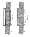
- FIG. 11 is a cross sectional diagram of a piezoelectric polymer film pulse detector integrated into the fabrication of a defibrillator pad.
- FIG. 12 is a cross sectional diagram of a piezoelectric polymer film pulse detector for use in a slightly concave body area such as that encountered in the area of the neck at the carotid artery.
- FIG. 13 is a schematic representation of a piezoelectric polymer film sensor element with a transimpedance (current to voltage converter) amplifier.
- FIG. 14 is a schematic representation of a piezoelectric polymer film sensor element with an integrating amplifier (charge amplifier).
- FIG. 15 is a schematic representation of a piezoelectric polymer film sensor element with a voltage amplifier.
- FIGS. 1 and 2 show methods of using a pulse sensor and defibrillator to determine the appropriate treatment for a victim who appears to be suffering from cardiac arrest. Both methods utilize a pulse sensor, described in further detail below, and an automated defibrillator.
- the automated defibrillator includes (a) a pair of electrodes that are placed on the victim's chest, (b) instrumentation constructed to receive signals from the electrodes, monitor the victim's ECG based on the received signals, and deliver a shock to the electrodes, and (c) a display constructed to display information and recommendations to the caregiver.
- Suitable automated defibrillators are commercially available from Zoll Medical Corp., Burlington, Mass., e.g., M-Series Automated External Defibrillators.
- the instrumentation also includes the capability of comparing the R-wave of the heart rhythm monitored by the ECG to the victim's pulse to determine whether the two signals are synchronized. Together, the pulse sensor and defibrillator constitute a treatment system for victims who appear to be suffering from cardiac arrest.
- FIG. 1 illustrates a method according to a first embodiment of the invention.
- the pulse sensor and defibrillator are used to control the initiation of ECG analysis and to advise a caregiver whether it is appropriate to administer a shock and/or CPR.
- a caregiver applies a pulse sensor and the electrodes of a defibrillator to the victim ( 100 ).
- the pulse sensor is applied by fastening an elastic strap 20 carrying the sensor element 22 around the victim's neck 24 , so that the sensor element 22 is held in close contact with the victim's carotid artery by the elastic strap 20 .
- the strap is fastened snugly but not tightly about the neck.
- the sensor should be placed on the left side of the neck orthogonal to and centered on the carotid artery.
- the neck is generally preferred since it is the measurement and sustenance of blood flow to the brain which is of ultimate importance and the carotid artery carrying this flow provides a strong signal if a pulse is present.
- the sensor element 22 is connected, e.g., by a coaxial cable, to instrumentation 26 , which is preferably incorporated in the instrumentation of the defibrillator.
- instrumentation 26 which is preferably incorporated in the instrumentation of the defibrillator.
- the electrodes of the defibrillator are applied in a conventional manner.
- the victim's pulse is detected and monitored by the pulse sensor, and the victim's heart rhythm is monitored by the ECG function of the defibrillator via the defibrillation pads.
- the instrumentation of the defibrillator determines whether the victim's pulse is correlated with the R-waves of the victim's heart rhythm ( 102 ). If the pulse and R-waves are synchronized, then a display on the defibrillator indicates to the caregiver that the victim does not appear to be in cardiac arrest, and that the victim should not be shocked or treated with CPR ( 104 ).
- the caregiver puts the victim in a “rescue” position, according to standard first aid protocol, and continues to monitor the victim's pulse and ECG ( 106 ) so as to observe if a change in synchronization, a loss of pulse signal or ventricular fibrillation should occur ( 108 ).
- the defibrillator then performs an ECG analysis ( 110 ) to determine whether the victim's heart rhythm should be treated by administering an electrical shock, i.e., whether the victim is suffering from ventricular fibrillation or wide complex ventricular tachycardia ( 112 ).
- an electrical shock i.e., whether the victim is suffering from ventricular fibrillation or wide complex ventricular tachycardia ( 112 ).
- the display of the defibrillator advises the caregiver to administer a shock to the victim ( 114 ).
- the caregiver delivers a shock to the victim, and the defibrillator then performs another ECG analysis to determine whether a shockable rhythm is detected ( 110 ). As long as a shockable rhythm is detected, this process is repeated for three shocks ( 116 ). Once three shocks have been administered, the system checks again to see whether the victim's pulse is synchronized with the R-waves ( 118 ). If synchronization is not detected, then the display advises the caregiver to administer CPR for a specified period of time ( 120 ) and then to discontinue CPR ( 122 ).
- a display on the defibrillator indicates to the caregiver that the victim does not appear to be in cardiac arrest, and that the victim should not be shocked or treated with CPR ( 104 ), and treatment proceeds as discussed above with reference to steps 106 - 108 .
- shockable rhythm is not detected, this indicates that either the victim is not suffering from cardiac arrest or that the victim has a condition that is not treatable by defibrillation ( 124 ).
- the system checks again to see whether the victim's pulse is synchronized with the R-waves ( 118 ), and treatment proceeds, based on the results, as discussed above.
- FIG. 2 illustrates an alternative method, in which the pulse sensor is used only to advise the caregiver whether it is appropriate to administer CPR.
- the ECG analysis is used alone to advise the caregiver whether it is appropriate to administer a defibrillation shock.
- This method may be used in cases in which checking the patient's pulse prior to applying the defibrillator electrodes is deemed to be unnecessary, e.g., the protocol that is currently recommended by the American Heart Association for lay caregivers.
- the other steps of the method shown in FIG. 2 are as described above with reference to FIG. 1 .
- the pulse sensor is a piezoelectric polymer sensor.
- Piezoelectric sensors are, in their simplest form, capacitive electromechanical transducers that generate electrical charge in proportion to applied stress.
- the primary purpose of these sensors in the present invention is to generate an electrical signal that is proportional to the force caused by blood flow (pulse) in the area of the carotid artery or other areas of the body where a pulse could be detected.
- the sensors of the invention are not mechanically clamped at their periphery, and are primarily sensitive to longitudinal stress as opposed to a sound pressure wave front. Although the sensor material is somewhat sensitive to stress applied normal to its thickness and width, the sensor is designed to be most sensitive to stresses applied normal to its length (or “machine direction”).
- the artery expands and exerts a small amount of stress on the sensor, which is in close contact with the exterior of the patient's neck, as discussed above.
- the stress induced in the sensor thus reflects changes in arterial blood flow.
- the sensor includes a piezoelectric polymer film 30 , a common metalization layer 32 and a signal metalization layer 34 .
- piezoelectric sensors are generally of very high impedance, electrical interference is often problematic.
- the sensor may be fabricated in a folded (self-shielding) manner, as shown in FIGS. 4 , 4 B and 4 D, so that the common metalization layer 32 almost completely envelops the exterior of the sensor.
- the sensor is shown prior to folding in FIGS. 4A and 4C (top and bottom views, respectively) in which the dashed line indicates the line about which the sensor is folded.
- the sensor is held in its folded position by a layer of compliant adhesive 36 ( FIG. 4 ).
- This shielding technique in conjunction with coaxial cable connections, greatly minimizes interference created by undesirable stray electrical fields.
- FIG. 7 A data acquisition scan performed using the pulse sensor of FIG. 4 is shown in FIG. 7 .
- the voltage signal level is approximately 100 my p-p with most of the energy being spectrally located at about 1.2 Hz, indicating a pulse rate of 72 beats/minute (bpm).
- Suitable piezoelectric polymer films include polyvinylidine fluoride (PVDF) and co-polymers thereof.
- PVDF polyvinylidine fluoride
- Such piezoelectric polymer films are commercially available, e.g., from Measurement Specialties, Inc. of Valley Forge, Pa. (e.g., Part No. 1-1004347-0).
- the thickness of the polymer film is between about 0.001 and 0.005 inch.
- a preferred sensor material is polarized piezoelectric polymer film sheet, about 28 micron ( ⁇ 0.001 inch) thick with a silver conductor printed on both sides for a total thickness of about 40 microns ( ⁇ 0.0015 inch).
- the sensor material may be approximately 5 inches in length and folded back upon itself with compliant adhesive, as shown in FIG. 4 , to create a self-shielded sensor that is approximately 1.0 inch in width and 2.5 inches in length.
- An electrical signal is produced (as measured between the ‘signal’ and the ‘shield’ electrodes) when any stress is applied (especially in the longitudinal axis) to the sensor.
- the circuit shown in FIG. 5 consists of a voltage source in series with a capacitor. This circuit is acceptable for visualization and modeling of sensor elements of this type as long as the frequency is below ultrasonic range.
- the capacitance exhibited by these sensors is approximately 10 nF and loss tangent is less than 0.02. Because the leakage is so low, it is generally necessary to eliminate long term buildup of charge (DC drift) on the electrodes due to triboelectric, pyroelectric or other phenomena especially when the sensor element is to be connected to a high (>10 meg ohm) impedance instrument. Eliminating this undesirable DC drift (charge buildup) is accomplished (at the expense of low frequency response) by placing a ‘termination’ resistor (10 Meg ohm) across (in parallel with) the sensor, as shown in FIG. 6 . The termination resistor allows charge to bleed off from the sensor thus eliminating long-term voltage drift. The loss of low frequency response does not generally pose a problem, as it is typically preferable to minimize low frequency ( ⁇ 1 Hz) response so as to attenuate signals due to breathing or other slow artifacts.
- FIG. 6 also shows the capacitance associated with the cable, which is used to connect the sensor to the instrumentation or other apparatus.
- the capacitance of the connecting cable appears in parallel with the capacitance of the sensor. This should not significantly impair the operation of the sensor as long as the cable capacitance is not appreciably large as compared to the capacitance of the sensor. If the sensor were operated in the ‘current’ mode (connected to a transimpedance amplifier, as shown in FIG. 13 , or a charge amplifier, as shown in FIG. 14 ) the effect of the cable capacitance on the entire sensor system operation would be eliminated since there would be no appreciable voltage for the cable capacitance to charge to.
- the sensor electronics shown in FIGS. 13-15 may be integrated onto the sensor, or may be connected as a remote sensing instrument.
- a piezoelectric polymer sensor element 22 ′ may be bonded to the surface of a compliant thickness member, e.g., a foam pad 50 as shown in FIGS. 8 and 9 , to form a sensor assembly.
- a coaxial cable and terminating resistor are affixed to the foam pad and electrically connected to the sensor element.
- An epoxy 48 is applied to the resistor/cable/sensor area for protection.
- This sensor is designed to be most sensitive to forces which are normal to the length of the sensor.
- a second foam pad (not shown) may be adhered over the resistor/cable/sensor area.
- the foam pad is preferably about 1 to 2 mm thick, more preferably about 1.5 mm.
- the foam pad 50 may be contoured in regions 51 to enhance signal sensitivity by allowing more stress to be felt by the sensor element 22 .
- the piezoelectric sensor may also be bonded to the surface of a neutral plane inducer 52 , i.e., a compliant but non-stretchable member that converts any flexure in the assembly into a tensile or compressive motion normal to the sensor's length.
- Piezoelectric polymer sensors may be bonded to both opposing surfaces of a foam pad (not shown). Because any flexure in this assembly will cause tensile force in one sensor while simultaneously causing compressive force in the other sensor, the combined electrical signal will be differential in nature with advantages in increased sensitivity and improved common mode rejection of unwanted signals such as noise or pyroelectric response due to temperature transients.
- the sensor element 22 (shown in FIG. 4 and described above) and foam pad 50 may be bonded to a defibrillator electrode 53 , so that the sensor element may be attached to the chest as part of the defibrillator electrode.
- the defibrillator electrode includes a pressure-sensitive adhesive 56 and a conductive hydrogel 58 , as is well known in the defibrillator field.
- a stiff low mass object 54 may be bonded to the adhesive side of the foam pad to aid in making intimate contact with the carotid artery in cases where there are areas of depression in the neck surface.
- the pulse sensor assembly may be used anywhere on the human body that a pulse can be detected, e.g., the neck, chest, wrist, arm or ankle.
- the unamplified voltage signal level output from the sensor should be in the approximate tenths of a volt range when properly affixed to an area of the body that exhibits a moderate pulse strength.
- the pulse sensor may be attached in a different manner, e.g., by a clip, as a patch, or using a suction device.
- Small surface mount type electrical components such as operational amplifiers, resistors and capacitors may be integrated onto the sensor element and used to amplify the signal, provide noise immunity, mitigate the effects of cabling (parasitic capacitance and/or equivalent series resistance), filter certain frequencies, integrate the sensor electrical charge over time, double integrate the sensor electrical charge over time, scale and/or offset signal output, or otherwise accomplish signal conditioning functions for the electrical signals produced by the sensor element.
- the pulse sensor may be used in conjunction with a non-automated defibrillator.
- the pulse sensor would be used by a trained caregiver as an aid in determining the proper course of treatment. The caregiver would observe displayed pulse and ECG signals and perform an independent analysis to determine the proper mode of treatment.
- This step is a signal processing technique that is sometimes used to improve performance when one or both of the signals are contaminated with artifacts.
- Other suitable techniques include autocorrelation processing, matched filter processing, and other pattern recognition schemes. In some cases, e.g., if the signals are relatively uncontaminated, none of these techniques are required.
Landscapes
- Health & Medical Sciences (AREA)
- Cardiology (AREA)
- Life Sciences & Earth Sciences (AREA)
- Engineering & Computer Science (AREA)
- Animal Behavior & Ethology (AREA)
- Veterinary Medicine (AREA)
- Biomedical Technology (AREA)
- Heart & Thoracic Surgery (AREA)
- Public Health (AREA)
- General Health & Medical Sciences (AREA)
- Nuclear Medicine, Radiotherapy & Molecular Imaging (AREA)
- Radiology & Medical Imaging (AREA)
- Surgery (AREA)
- Molecular Biology (AREA)
- Medical Informatics (AREA)
- Physics & Mathematics (AREA)
- Biophysics (AREA)
- Pathology (AREA)
- Critical Care (AREA)
- Emergency Medicine (AREA)
- Electrotherapy Devices (AREA)
Abstract
Description
Claims (30)
Priority Applications (1)
Application Number | Priority Date | Filing Date | Title |
---|---|---|---|
US12/874,335 US8064995B1 (en) | 2001-05-01 | 2010-09-02 | Pulse sensors |
Applications Claiming Priority (3)
Application Number | Priority Date | Filing Date | Title |
---|---|---|---|
US09/846,673 US20020165585A1 (en) | 2001-05-01 | 2001-05-01 | Pulse sensors |
US10/992,402 US7797043B1 (en) | 2001-05-01 | 2004-11-17 | Pulse sensors |
US12/874,335 US8064995B1 (en) | 2001-05-01 | 2010-09-02 | Pulse sensors |
Related Parent Applications (1)
Application Number | Title | Priority Date | Filing Date |
---|---|---|---|
US10/992,402 Continuation US7797043B1 (en) | 2001-05-01 | 2004-11-17 | Pulse sensors |
Publications (1)
Publication Number | Publication Date |
---|---|
US8064995B1 true US8064995B1 (en) | 2011-11-22 |
Family
ID=25298611
Family Applications (3)
Application Number | Title | Priority Date | Filing Date |
---|---|---|---|
US09/846,673 Abandoned US20020165585A1 (en) | 2001-05-01 | 2001-05-01 | Pulse sensors |
US10/992,402 Expired - Fee Related US7797043B1 (en) | 2001-05-01 | 2004-11-17 | Pulse sensors |
US12/874,335 Expired - Fee Related US8064995B1 (en) | 2001-05-01 | 2010-09-02 | Pulse sensors |
Family Applications Before (2)
Application Number | Title | Priority Date | Filing Date |
---|---|---|---|
US09/846,673 Abandoned US20020165585A1 (en) | 2001-05-01 | 2001-05-01 | Pulse sensors |
US10/992,402 Expired - Fee Related US7797043B1 (en) | 2001-05-01 | 2004-11-17 | Pulse sensors |
Country Status (1)
Country | Link |
---|---|
US (3) | US20020165585A1 (en) |
Cited By (13)
Publication number | Priority date | Publication date | Assignee | Title |
---|---|---|---|---|
US8401637B2 (en) | 2004-11-24 | 2013-03-19 | Galvani, Ltd. | Medium voltage therapy applications in treating cardiac arrest |
CN103007431A (en) * | 2012-12-31 | 2013-04-03 | 深圳邦健生物医疗设备股份有限公司 | Device and method for shockable signal detection |
US8483822B1 (en) | 2009-07-02 | 2013-07-09 | Galvani, Ltd. | Adaptive medium voltage therapy for cardiac arrhythmias |
US8768440B1 (en) | 2013-03-15 | 2014-07-01 | Apn Health, Llc | Multi-channel cardiac measurements |
US8812091B1 (en) | 2013-03-15 | 2014-08-19 | Apn Health, Llc | Multi-channel cardiac measurements |
US9078575B2 (en) | 2013-10-30 | 2015-07-14 | Apn Health, Llc | Heartbeat categorization |
US9078572B2 (en) | 2013-10-30 | 2015-07-14 | Apn Health, Llc | Heartbeat detection and categorization |
US9126055B2 (en) | 2012-04-20 | 2015-09-08 | Cardiac Science Corporation | AED faster time to shock method and device |
US9314179B1 (en) | 2014-09-25 | 2016-04-19 | Apn Health, Llc | Time transformation of local activation times |
US9421391B2 (en) | 2012-12-12 | 2016-08-23 | Galvani, Ltd. | Coordinated medium voltage therapy for improving effectiveness of defibrillation therapy |
US10357168B2 (en) | 2016-03-07 | 2019-07-23 | Apn Health, Llc | Time transformation of local activation times |
US10998925B2 (en) * | 2018-05-14 | 2021-05-04 | Purdue Research Foundation | Wearable health monitoring system and method using human body communication |
US11089989B2 (en) | 2018-09-14 | 2021-08-17 | Avive Solutions, Inc. | Shockable heart rhythm classifier for defibrillators |
Families Citing this family (32)
Publication number | Priority date | Publication date | Assignee | Title |
---|---|---|---|---|
US6440082B1 (en) * | 1999-09-30 | 2002-08-27 | Medtronic Physio-Control Manufacturing Corp. | Method and apparatus for using heart sounds to determine the presence of a pulse |
US9248306B2 (en) | 1999-09-30 | 2016-02-02 | Physio-Control, Inc. | Pulse detection apparatus, software, and methods using patient physiological signals |
US20040039419A1 (en) * | 1999-09-30 | 2004-02-26 | Stickney Ronald E. | Apparatus, software, and methods for cardiac pulse detection using a piezoelectric sensor |
US20030109790A1 (en) * | 2001-12-06 | 2003-06-12 | Medtronic Physio-Control Manufacturing Corp. | Pulse detection method and apparatus using patient impedance |
JP2003521355A (en) | 2000-02-04 | 2003-07-15 | ゼットエムデー コーポレイション | Integrated resuscitation |
US20020165585A1 (en) | 2001-05-01 | 2002-11-07 | Dupelle Michael R. | Pulse sensors |
US20040116969A1 (en) | 2002-08-26 | 2004-06-17 | Owen James M. | Pulse detection using patient physiological signals |
US20040039420A1 (en) * | 2002-08-26 | 2004-02-26 | Medtronic Physio-Control Manufacturing Corp. | Apparatus, software, and methods for cardiac pulse detection using accelerometer data |
US6827695B2 (en) | 2002-10-25 | 2004-12-07 | Revivant Corporation | Method of determining depth of compressions during cardio-pulmonary resuscitation |
US7272441B1 (en) * | 2002-11-13 | 2007-09-18 | Medtronic Physio-Control Manufacturing Corp. | External defibrillator and methods for operating the external defibrillator |
US7970464B2 (en) * | 2002-11-13 | 2011-06-28 | Physio-Control, Inc. | Method and system for responding to non-perfusing and non-shockable heart rhythms |
US7569018B1 (en) * | 2003-02-18 | 2009-08-04 | Purdue Research Foundation | Apparatus and method for noninvasively detecting the quality of cardiac pumping |
US6961612B2 (en) * | 2003-02-19 | 2005-11-01 | Zoll Medical Corporation | CPR sensitive ECG analysis in an automatic external defibrillator |
US20040215244A1 (en) * | 2003-04-23 | 2004-10-28 | Marcovecchio Alan F. | Processing pulse signal in conjunction with ECG signal to detect pulse in external defibrillation |
US7220235B2 (en) * | 2003-06-27 | 2007-05-22 | Zoll Medical Corporation | Method and apparatus for enhancement of chest compressions during CPR |
US7190999B2 (en) * | 2003-06-27 | 2007-03-13 | Zoll Medical Corporation | Cardio-pulmonary resuscitation device with feedback from measurement of pulse and/or blood oxygenation |
JP2012091021A (en) | 2003-11-06 | 2012-05-17 | Zoll Medical Corp | Device for analyzing physiological signal during application of chest compression |
US20050101889A1 (en) | 2003-11-06 | 2005-05-12 | Freeman Gary A. | Using chest velocity to process physiological signals to remove chest compression artifacts |
WO2005112749A1 (en) | 2004-05-12 | 2005-12-01 | Zoll Medical Corporation | Ecg rhythm advisory method |
US7565194B2 (en) | 2004-05-12 | 2009-07-21 | Zoll Medical Corporation | ECG rhythm advisory method |
CN101262814B (en) * | 2005-07-15 | 2010-12-08 | 皇家飞利浦电子股份有限公司 | Apparatus for defibrillation pulse detection using electromagnetic waves |
US20080177341A1 (en) * | 2006-10-27 | 2008-07-24 | Bowers Kyle R | Automated external defibrillator (AED) system with multiple patient wireless monitoring capability for use in mass casualty incidents |
KR101023446B1 (en) * | 2007-09-21 | 2011-03-25 | 주식회사 바이오에이비씨랩 | Sensors containing materials that generate electrical signals by stretching |
US20130282068A1 (en) * | 2012-04-20 | 2013-10-24 | Mustafa H. Sagiroglu | Aed treatment recommendation method and device |
JP6321980B2 (en) * | 2013-03-09 | 2018-05-09 | キヤノン株式会社 | Detection circuit, driving method, probe, and subject information acquisition apparatus |
EP2969034A4 (en) | 2013-03-15 | 2016-11-30 | Zoll Medical Corp | IMPEDANCE SIGNAL PROCESSING FOR BREATHING DETECTION |
JP2016512762A (en) | 2013-03-15 | 2016-05-09 | ゾル メディカル コーポレーションZoll Medical Corporation | ECG noise reduction system for vehicle motion artifact removal |
US10596064B2 (en) | 2014-03-18 | 2020-03-24 | Zoll Medical Corporation | CPR chest compression system with tonometric input and feedback |
US9572507B2 (en) | 2014-09-10 | 2017-02-21 | Dymedix Corporation | Combination physiologic sensor |
EP3274048B1 (en) | 2015-03-27 | 2020-02-26 | Zoll Medical Corporation | Ecg and defibrillator electrode detection and tracking system |
EP3362143B1 (en) | 2015-10-16 | 2023-09-27 | Zoll Medical Corporation | Dual sensor electrodes for providing enhanced resuscitation feedback |
WO2022165179A1 (en) | 2021-01-28 | 2022-08-04 | Usa Medical Electronix, Inc. | Pocket-sized automated external defibrillator |
Citations (41)
Publication number | Priority date | Publication date | Assignee | Title |
---|---|---|---|---|
US3716059A (en) | 1970-08-24 | 1973-02-13 | Cardiac Resuscitator Corp | Cardiac resuscitator |
US3903873A (en) | 1974-05-13 | 1975-09-09 | Douglas E Royal | Pulse contour measuring instrument |
US4052979A (en) | 1975-12-04 | 1977-10-11 | Mary Ann Scherr | Jewelry and bracelet heartbeat monitor |
US4299233A (en) | 1979-10-03 | 1981-11-10 | Lemelson Jerome H | Patient monitoring device and method |
US4331154A (en) | 1979-10-15 | 1982-05-25 | Tech Engineering & Design | Blood pressure and heart rate measuring watch |
US4443730A (en) | 1978-11-15 | 1984-04-17 | Mitsubishi Petrochemical Co., Ltd. | Biological piezoelectric transducer device for the living body |
US4722347A (en) | 1985-01-15 | 1988-02-02 | Applied Biometrics, Inc. | Apparatus for measuring cardiac output |
JPS6326716A (en) | 1986-07-18 | 1988-02-04 | Nec Ic Microcomput Syst Ltd | Central processing unit |
US4911167A (en) | 1985-06-07 | 1990-03-27 | Nellcor Incorporated | Method and apparatus for detecting optical pulses |
JPH0415038A (en) | 1990-05-10 | 1992-01-20 | Matsushita Electric Ind Co Ltd | Living body monitoring device |
JPH0428345A (en) | 1990-05-25 | 1992-01-30 | Matsushita Electric Ind Co Ltd | Living body monitoring device |
JPH0428344A (en) | 1990-05-25 | 1992-01-30 | Matsushita Electric Ind Co Ltd | On-bed state monitoring device |
US5086776A (en) | 1990-03-06 | 1992-02-11 | Precision Diagnostics, Inc. | Apparatus and method for sensing cardiac performance |
JPH05261071A (en) | 1992-03-19 | 1993-10-12 | Matsushita Electric Ind Co Ltd | On-vehicle heart beat detector |
WO1995006525A1 (en) | 1993-08-30 | 1995-03-09 | Medacoustics, Inc. | Disposable acoustic pad sensors |
US5409009A (en) | 1994-03-18 | 1995-04-25 | Medtronic, Inc. | Methods for measurement of arterial blood flow |
US5431685A (en) | 1992-04-03 | 1995-07-11 | Intermedics, Inc. | Implantable medical interventional device with criteria modification to enhance recognition of Tachycardia |
JPH07265272A (en) | 1994-04-01 | 1995-10-17 | Itec Kk | Nursing/monitoring system |
US5595188A (en) | 1995-07-26 | 1997-01-21 | Flowscan, Inc. | Assembly process for polymer-based acoustic differential-output sensor |
US5645571A (en) | 1995-08-01 | 1997-07-08 | Survivalink Corporation | Automated external defibrillator with lid activated self-test system |
US5795300A (en) | 1994-06-01 | 1998-08-18 | Advanced Body Metrics Corporation | Heart pulse monitor |
US5807268A (en) | 1992-09-09 | 1998-09-15 | Medacoustics, Inc. | Disposable sensing device with contaneous conformance |
US5807267A (en) | 1994-06-01 | 1998-09-15 | Advanced Body Metrics Corporation | Heart pulse monitor |
US5827198A (en) | 1996-11-21 | 1998-10-27 | Flowscan, Inc. | Low-cost, disposable, polymer-based, differential output flexure sensor and method of fabricating same |
US5967995A (en) | 1998-04-28 | 1999-10-19 | University Of Pittsburgh Of The Commonwealth System Of Higher Education | System for prediction of life-threatening cardiac arrhythmias |
US5978703A (en) * | 1994-05-31 | 1999-11-02 | Galvani, Ltd. | Method and apparatus for temporarily electrically forcing cardiac output in a tachyarrhythmia patient |
US5991661A (en) | 1997-10-17 | 1999-11-23 | Pacesetter, Inc. | System and method for measuring cardiac activity |
WO2001022885A1 (en) | 1999-09-30 | 2001-04-05 | Medtronic Physio-Control Manufacturing Corp. | Method and apparatus for using heart sounds to determine the presence of a pulse |
US6292692B1 (en) | 1999-04-30 | 2001-09-18 | Medical Research Laboratories, Inc. | Medical treatment device with functions, operated under passcode control |
US6298267B1 (en) | 1999-04-30 | 2001-10-02 | Intermedics Inc. | Method and apparatus for treatment of cardiac electromechanical dissociation |
US6304773B1 (en) | 1998-05-21 | 2001-10-16 | Medtronic Physio-Control Manufacturing Corp. | Automatic detection and reporting of cardiac asystole |
US20010047140A1 (en) | 2000-02-04 | 2001-11-29 | Freeman Gary A. | Integrated resuscitation |
US6356785B1 (en) | 1997-11-06 | 2002-03-12 | Cecily Anne Snyder | External defibrillator with CPR prompts and ACLS prompts and methods of use |
US20020165585A1 (en) | 2001-05-01 | 2002-11-07 | Dupelle Michael R. | Pulse sensors |
US20020173725A1 (en) | 2001-05-18 | 2002-11-21 | Rock Joseph E. | Integrated cardiac resuscitation system with ability to detect perfusion |
US6487442B1 (en) | 2000-04-28 | 2002-11-26 | Nicholas Wood | Detection of abnormal and induction of normal heat rate variability |
US6591135B2 (en) | 2001-04-16 | 2003-07-08 | Ge Medical Systems Information Technologies, Inc. | Portable patient monitor with defibrillator/pacemaker interface and battery power management |
US20040039420A1 (en) | 2002-08-26 | 2004-02-26 | Medtronic Physio-Control Manufacturing Corp. | Apparatus, software, and methods for cardiac pulse detection using accelerometer data |
JP4015038B2 (en) | 2003-02-14 | 2007-11-28 | 古河電気工業株式会社 | Flat cable connection terminal and connection part of flat cable and connection terminal |
JP4028344B2 (en) | 2001-10-19 | 2007-12-26 | ホシザキ電機株式会社 | Storage |
JP4028345B2 (en) | 2002-10-16 | 2007-12-26 | 古河電気工業株式会社 | Design method of flat conductor for flat cable and flat cable |
Family Cites Families (1)
Publication number | Priority date | Publication date | Assignee | Title |
---|---|---|---|---|
US6050950A (en) | 1996-12-18 | 2000-04-18 | Aurora Holdings, Llc | Passive/non-invasive systemic and pulmonary blood pressure measurement |
-
2001
- 2001-05-01 US US09/846,673 patent/US20020165585A1/en not_active Abandoned
-
2004
- 2004-11-17 US US10/992,402 patent/US7797043B1/en not_active Expired - Fee Related
-
2010
- 2010-09-02 US US12/874,335 patent/US8064995B1/en not_active Expired - Fee Related
Patent Citations (48)
Publication number | Priority date | Publication date | Assignee | Title |
---|---|---|---|---|
US3716059A (en) | 1970-08-24 | 1973-02-13 | Cardiac Resuscitator Corp | Cardiac resuscitator |
US3903873A (en) | 1974-05-13 | 1975-09-09 | Douglas E Royal | Pulse contour measuring instrument |
US4052979A (en) | 1975-12-04 | 1977-10-11 | Mary Ann Scherr | Jewelry and bracelet heartbeat monitor |
US4443730A (en) | 1978-11-15 | 1984-04-17 | Mitsubishi Petrochemical Co., Ltd. | Biological piezoelectric transducer device for the living body |
US4299233A (en) | 1979-10-03 | 1981-11-10 | Lemelson Jerome H | Patient monitoring device and method |
US4331154A (en) | 1979-10-15 | 1982-05-25 | Tech Engineering & Design | Blood pressure and heart rate measuring watch |
US4722347A (en) | 1985-01-15 | 1988-02-02 | Applied Biometrics, Inc. | Apparatus for measuring cardiac output |
US4911167A (en) | 1985-06-07 | 1990-03-27 | Nellcor Incorporated | Method and apparatus for detecting optical pulses |
JPS6326716A (en) | 1986-07-18 | 1988-02-04 | Nec Ic Microcomput Syst Ltd | Central processing unit |
US5086776A (en) | 1990-03-06 | 1992-02-11 | Precision Diagnostics, Inc. | Apparatus and method for sensing cardiac performance |
JPH0415038A (en) | 1990-05-10 | 1992-01-20 | Matsushita Electric Ind Co Ltd | Living body monitoring device |
JPH0428345A (en) | 1990-05-25 | 1992-01-30 | Matsushita Electric Ind Co Ltd | Living body monitoring device |
JPH0428344A (en) | 1990-05-25 | 1992-01-30 | Matsushita Electric Ind Co Ltd | On-bed state monitoring device |
JPH05261071A (en) | 1992-03-19 | 1993-10-12 | Matsushita Electric Ind Co Ltd | On-vehicle heart beat detector |
US5431685A (en) | 1992-04-03 | 1995-07-11 | Intermedics, Inc. | Implantable medical interventional device with criteria modification to enhance recognition of Tachycardia |
US5807268A (en) | 1992-09-09 | 1998-09-15 | Medacoustics, Inc. | Disposable sensing device with contaneous conformance |
US5913829A (en) | 1992-09-09 | 1999-06-22 | Medacoustics, Inc. | Sensing device for acoustic energy |
US5885222A (en) | 1993-08-30 | 1999-03-23 | Medacoustics, Inc. | Disposable acoustic pad sensors |
WO1995006525A1 (en) | 1993-08-30 | 1995-03-09 | Medacoustics, Inc. | Disposable acoustic pad sensors |
US5409009A (en) | 1994-03-18 | 1995-04-25 | Medtronic, Inc. | Methods for measurement of arterial blood flow |
JPH07265272A (en) | 1994-04-01 | 1995-10-17 | Itec Kk | Nursing/monitoring system |
US5978703A (en) * | 1994-05-31 | 1999-11-02 | Galvani, Ltd. | Method and apparatus for temporarily electrically forcing cardiac output in a tachyarrhythmia patient |
US6567697B1 (en) | 1994-05-31 | 2003-05-20 | Galvani, Ltd. | External defibrillator with electrical CPR assist |
US5807267A (en) | 1994-06-01 | 1998-09-15 | Advanced Body Metrics Corporation | Heart pulse monitor |
US5795300A (en) | 1994-06-01 | 1998-08-18 | Advanced Body Metrics Corporation | Heart pulse monitor |
US5595188A (en) | 1995-07-26 | 1997-01-21 | Flowscan, Inc. | Assembly process for polymer-based acoustic differential-output sensor |
US5645571A (en) | 1995-08-01 | 1997-07-08 | Survivalink Corporation | Automated external defibrillator with lid activated self-test system |
US5645571B1 (en) | 1995-08-01 | 1999-08-24 | Surviva Link Corp | Automated external defibrillator with lid activated self-test system |
US5827198A (en) | 1996-11-21 | 1998-10-27 | Flowscan, Inc. | Low-cost, disposable, polymer-based, differential output flexure sensor and method of fabricating same |
US5991661A (en) | 1997-10-17 | 1999-11-23 | Pacesetter, Inc. | System and method for measuring cardiac activity |
US6356785B1 (en) | 1997-11-06 | 2002-03-12 | Cecily Anne Snyder | External defibrillator with CPR prompts and ACLS prompts and methods of use |
US5967995A (en) | 1998-04-28 | 1999-10-19 | University Of Pittsburgh Of The Commonwealth System Of Higher Education | System for prediction of life-threatening cardiac arrhythmias |
US6304773B1 (en) | 1998-05-21 | 2001-10-16 | Medtronic Physio-Control Manufacturing Corp. | Automatic detection and reporting of cardiac asystole |
US6298267B1 (en) | 1999-04-30 | 2001-10-02 | Intermedics Inc. | Method and apparatus for treatment of cardiac electromechanical dissociation |
US6292692B1 (en) | 1999-04-30 | 2001-09-18 | Medical Research Laboratories, Inc. | Medical treatment device with functions, operated under passcode control |
US20030060723A1 (en) | 1999-09-30 | 2003-03-27 | Medtronic Physio-Control Manufacturing Corp. | Pulse detection apparatus, software, and methods using patient physiological signals |
US6440082B1 (en) | 1999-09-30 | 2002-08-27 | Medtronic Physio-Control Manufacturing Corp. | Method and apparatus for using heart sounds to determine the presence of a pulse |
WO2001022885A1 (en) | 1999-09-30 | 2001-04-05 | Medtronic Physio-Control Manufacturing Corp. | Method and apparatus for using heart sounds to determine the presence of a pulse |
US20010047140A1 (en) | 2000-02-04 | 2001-11-29 | Freeman Gary A. | Integrated resuscitation |
US6487442B1 (en) | 2000-04-28 | 2002-11-26 | Nicholas Wood | Detection of abnormal and induction of normal heat rate variability |
US6591135B2 (en) | 2001-04-16 | 2003-07-08 | Ge Medical Systems Information Technologies, Inc. | Portable patient monitor with defibrillator/pacemaker interface and battery power management |
US20020165585A1 (en) | 2001-05-01 | 2002-11-07 | Dupelle Michael R. | Pulse sensors |
US20020173725A1 (en) | 2001-05-18 | 2002-11-21 | Rock Joseph E. | Integrated cardiac resuscitation system with ability to detect perfusion |
US6575914B2 (en) | 2001-05-18 | 2003-06-10 | Koninklijke Philips Electronics N.V. | Integrated cardiac resuscitation system with ability to detect perfusion |
JP4028344B2 (en) | 2001-10-19 | 2007-12-26 | ホシザキ電機株式会社 | Storage |
US20040039420A1 (en) | 2002-08-26 | 2004-02-26 | Medtronic Physio-Control Manufacturing Corp. | Apparatus, software, and methods for cardiac pulse detection using accelerometer data |
JP4028345B2 (en) | 2002-10-16 | 2007-12-26 | 古河電気工業株式会社 | Design method of flat conductor for flat cable and flat cable |
JP4015038B2 (en) | 2003-02-14 | 2007-11-28 | 古河電気工業株式会社 | Flat cable connection terminal and connection part of flat cable and connection terminal |
Non-Patent Citations (2)
Title |
---|
Kassal et al., "Polymer-Based Adherent Differential-Output Sensor for Cardiac Auscultation," Medical Electronics, vol. 25, No. 4, Issue 148, pp. 54-63 (Sep. 1994). |
Webster, John G., Medical Instrumentation, Application and Design, 3rd ed., New York, NY, John J. Wiley & Sons, Inc. 1998. |
Cited By (16)
Publication number | Priority date | Publication date | Assignee | Title |
---|---|---|---|---|
US8401637B2 (en) | 2004-11-24 | 2013-03-19 | Galvani, Ltd. | Medium voltage therapy applications in treating cardiac arrest |
US8483822B1 (en) | 2009-07-02 | 2013-07-09 | Galvani, Ltd. | Adaptive medium voltage therapy for cardiac arrhythmias |
US9144684B2 (en) | 2009-07-02 | 2015-09-29 | Galvani, Ltd. | Medium voltage therapy applied as a test of a physiologic state |
US9126055B2 (en) | 2012-04-20 | 2015-09-08 | Cardiac Science Corporation | AED faster time to shock method and device |
US9421391B2 (en) | 2012-12-12 | 2016-08-23 | Galvani, Ltd. | Coordinated medium voltage therapy for improving effectiveness of defibrillation therapy |
CN103007431A (en) * | 2012-12-31 | 2013-04-03 | 深圳邦健生物医疗设备股份有限公司 | Device and method for shockable signal detection |
US8788024B1 (en) | 2013-03-15 | 2014-07-22 | Apn Health, Llc | Multi-channel cardiac measurements |
US8812091B1 (en) | 2013-03-15 | 2014-08-19 | Apn Health, Llc | Multi-channel cardiac measurements |
US8768440B1 (en) | 2013-03-15 | 2014-07-01 | Apn Health, Llc | Multi-channel cardiac measurements |
US9078572B2 (en) | 2013-10-30 | 2015-07-14 | Apn Health, Llc | Heartbeat detection and categorization |
US9078575B2 (en) | 2013-10-30 | 2015-07-14 | Apn Health, Llc | Heartbeat categorization |
US9314179B1 (en) | 2014-09-25 | 2016-04-19 | Apn Health, Llc | Time transformation of local activation times |
US10357168B2 (en) | 2016-03-07 | 2019-07-23 | Apn Health, Llc | Time transformation of local activation times |
US10998925B2 (en) * | 2018-05-14 | 2021-05-04 | Purdue Research Foundation | Wearable health monitoring system and method using human body communication |
US11089989B2 (en) | 2018-09-14 | 2021-08-17 | Avive Solutions, Inc. | Shockable heart rhythm classifier for defibrillators |
US11903741B2 (en) | 2018-09-14 | 2024-02-20 | Avive Solutions, Inc. | Shockable heart rhythm classifier for defibrillators |
Also Published As
Publication number | Publication date |
---|---|
US7797043B1 (en) | 2010-09-14 |
US20020165585A1 (en) | 2002-11-07 |
Similar Documents
Publication | Publication Date | Title |
---|---|---|
US8064995B1 (en) | Pulse sensors | |
US7074199B2 (en) | CPR chest compression monitor and method of use | |
US20180199910A1 (en) | Therapeutic device including acoustic sensor | |
AU778336B2 (en) | Method and system of determining whether a lifeless person has a pulse | |
US20100022886A1 (en) | CPR Guided by Vascular Flow Measurement | |
US20100210947A1 (en) | Vascular Flow Sensor With Acoustic Coupling Detector | |
US20090306525A1 (en) | Apparatus and Method for Defibrillation Pulse Detection Using Electromagnetic Waves | |
JP2004533876A (en) | Integrated cardiac resuscitation system with perfusion detection | |
JPH10179769A (en) | Cardiac defibrillation apparatus |
Legal Events
Date | Code | Title | Description |
---|---|---|---|
AS | Assignment |
Owner name: ZOLL MEDICAL CORPORATION, MASSACHUSETTS Free format text: MERGER;ASSIGNOR:ZMD CORPORATION;REEL/FRAME:025461/0038 Effective date: 20031120 Owner name: ZMD CORPORATION, DELAWARE Free format text: ASSIGNMENT OF ASSIGNORS INTEREST;ASSIGNORS:DUPELLE, MICHAEL R.;PREW, PAUL F.;WHITE, SHELDON S.;REEL/FRAME:025460/0895 Effective date: 20010518 |
|
STCF | Information on status: patent grant |
Free format text: PATENTED CASE |
|
FPAY | Fee payment |
Year of fee payment: 4 |
|
MAFP | Maintenance fee payment |
Free format text: PAYMENT OF MAINTENANCE FEE, 8TH YEAR, LARGE ENTITY (ORIGINAL EVENT CODE: M1552); ENTITY STATUS OF PATENT OWNER: LARGE ENTITY Year of fee payment: 8 |
|
FEPP | Fee payment procedure |
Free format text: MAINTENANCE FEE REMINDER MAILED (ORIGINAL EVENT CODE: REM.); ENTITY STATUS OF PATENT OWNER: LARGE ENTITY |
|
LAPS | Lapse for failure to pay maintenance fees |
Free format text: PATENT EXPIRED FOR FAILURE TO PAY MAINTENANCE FEES (ORIGINAL EVENT CODE: EXP.); ENTITY STATUS OF PATENT OWNER: LARGE ENTITY |
|
STCH | Information on status: patent discontinuation |
Free format text: PATENT EXPIRED DUE TO NONPAYMENT OF MAINTENANCE FEES UNDER 37 CFR 1.362 |
|
FP | Lapsed due to failure to pay maintenance fee |
Effective date: 20231122 |