US8019181B2 - Image generation apparatus, image processing apparatus, computer readable medium and computer data signal - Google Patents
Image generation apparatus, image processing apparatus, computer readable medium and computer data signal Download PDFInfo
- Publication number
- US8019181B2 US8019181B2 US11/785,330 US78533007A US8019181B2 US 8019181 B2 US8019181 B2 US 8019181B2 US 78533007 A US78533007 A US 78533007A US 8019181 B2 US8019181 B2 US 8019181B2
- Authority
- US
- United States
- Prior art keywords
- pattern
- image
- information
- pattern images
- code
- Prior art date
- Legal status (The legal status is an assumption and is not a legal conclusion. Google has not performed a legal analysis and makes no representation as to the accuracy of the status listed.)
- Expired - Fee Related, expires
Links
- 238000012545 processing Methods 0.000 title claims description 29
- 238000005192 partition Methods 0.000 claims abstract description 27
- 238000000034 method Methods 0.000 claims description 74
- 238000010521 absorption reaction Methods 0.000 claims description 6
- 230000015572 biosynthetic process Effects 0.000 claims description 5
- 230000001360 synchronised effect Effects 0.000 description 188
- 238000001514 detection method Methods 0.000 description 136
- 238000004891 communication Methods 0.000 description 6
- 238000010586 diagram Methods 0.000 description 6
- 238000000926 separation method Methods 0.000 description 6
- 239000000284 extract Substances 0.000 description 5
- 238000012937 correction Methods 0.000 description 3
- 230000006870 function Effects 0.000 description 3
- 238000003384 imaging method Methods 0.000 description 3
- 238000006073 displacement reaction Methods 0.000 description 2
- 238000012986 modification Methods 0.000 description 2
- 230000004048 modification Effects 0.000 description 2
- OKTJSMMVPCPJKN-UHFFFAOYSA-N Carbon Chemical compound [C] OKTJSMMVPCPJKN-UHFFFAOYSA-N 0.000 description 1
- 229910052799 carbon Inorganic materials 0.000 description 1
- 230000000295 complement effect Effects 0.000 description 1
- 238000001914 filtration Methods 0.000 description 1
- 230000000873 masking effect Effects 0.000 description 1
- 229910044991 metal oxide Inorganic materials 0.000 description 1
- 150000004706 metal oxides Chemical class 0.000 description 1
- 230000005855 radiation Effects 0.000 description 1
- 239000004065 semiconductor Substances 0.000 description 1
- 230000035945 sensitivity Effects 0.000 description 1
- 230000000007 visual effect Effects 0.000 description 1
Images


Classifications
-
- G—PHYSICS
- G06—COMPUTING; CALCULATING OR COUNTING
- G06K—GRAPHICAL DATA READING; PRESENTATION OF DATA; RECORD CARRIERS; HANDLING RECORD CARRIERS
- G06K19/00—Record carriers for use with machines and with at least a part designed to carry digital markings
- G06K19/06—Record carriers for use with machines and with at least a part designed to carry digital markings characterised by the kind of the digital marking, e.g. shape, nature, code
- G06K19/06009—Record carriers for use with machines and with at least a part designed to carry digital markings characterised by the kind of the digital marking, e.g. shape, nature, code with optically detectable marking
- G06K19/06037—Record carriers for use with machines and with at least a part designed to carry digital markings characterised by the kind of the digital marking, e.g. shape, nature, code with optically detectable marking multi-dimensional coding
-
- G—PHYSICS
- G06—COMPUTING; CALCULATING OR COUNTING
- G06F—ELECTRIC DIGITAL DATA PROCESSING
- G06F3/00—Input arrangements for transferring data to be processed into a form capable of being handled by the computer; Output arrangements for transferring data from processing unit to output unit, e.g. interface arrangements
- G06F3/01—Input arrangements or combined input and output arrangements for interaction between user and computer
- G06F3/03—Arrangements for converting the position or the displacement of a member into a coded form
- G06F3/033—Pointing devices displaced or positioned by the user, e.g. mice, trackballs, pens or joysticks; Accessories therefor
- G06F3/0354—Pointing devices displaced or positioned by the user, e.g. mice, trackballs, pens or joysticks; Accessories therefor with detection of 2D relative movements between the device, or an operating part thereof, and a plane or surface, e.g. 2D mice, trackballs, pens or pucks
- G06F3/03545—Pens or stylus
-
- G—PHYSICS
- G06—COMPUTING; CALCULATING OR COUNTING
- G06K—GRAPHICAL DATA READING; PRESENTATION OF DATA; RECORD CARRIERS; HANDLING RECORD CARRIERS
- G06K7/00—Methods or arrangements for sensing record carriers, e.g. for reading patterns
- G06K7/10—Methods or arrangements for sensing record carriers, e.g. for reading patterns by electromagnetic radiation, e.g. optical sensing; by corpuscular radiation
- G06K7/10544—Methods or arrangements for sensing record carriers, e.g. for reading patterns by electromagnetic radiation, e.g. optical sensing; by corpuscular radiation by scanning of the records by radiation in the optical part of the electromagnetic spectrum
- G06K7/10821—Methods or arrangements for sensing record carriers, e.g. for reading patterns by electromagnetic radiation, e.g. optical sensing; by corpuscular radiation by scanning of the records by radiation in the optical part of the electromagnetic spectrum further details of bar or optical code scanning devices
- G06K7/10881—Methods or arrangements for sensing record carriers, e.g. for reading patterns by electromagnetic radiation, e.g. optical sensing; by corpuscular radiation by scanning of the records by radiation in the optical part of the electromagnetic spectrum further details of bar or optical code scanning devices constructional details of hand-held scanners
Definitions
- the invention relates to an image generation apparatus, an image processing apparatus, a computer readable medium and a computer data signal.
- an image generation apparatus includes an acquisition unit and a generation unit.
- the acquisition unit acquires information to be embedded in each of a plurality of partitions on a recording medium.
- the generation unit generates an image in which first pattern images representing the information and a second pattern image controlling acquisition of the information from the first pattern images are placed in each of the plurality of partitions.
- the first and second pattern images are ones of m C n pattern images which are obtained by placing a unit image in n points selected from among m points where m and n are natural numbers, m ⁇ 4, and 2 ⁇ n ⁇ m.
- FIG. 1A is a drawing to show an example of a unit code pattern in a 9 C n system
- FIG. 1B is a drawing to show another example of the unit code pattern in the 9 C n system
- FIG. 2A is a drawing to show an example of a unit code pattern in a 4 C n system
- FIG. 2B is a drawing to show another example of the unit code pattern in the 4 C n system
- FIG. 2C is a drawing to show an example of a unit code pattern in a 16 C n system
- FIG. 2D is a drawing to show another example of the unit code pattern in a 16 C n system;
- FIG. 3A is a drawing to show other examples of the unit code patterns in the 9 C n system
- FIG. 3B is a drawing to show further other example of the unit code patterns in the 9 C n system
- FIG. 3C is a drawing to show other examples of the unit code patterns in the 9 C n system;
- FIG. 4 is a drawing to show other examples of the unit code patterns in the 16 C n system
- FIG. 5A is a drawing to show examples of unit code patterns in a 6 C n system
- FIG. 5B is a drawing to show other examples of the unit code patterns in the 6 C n system
- FIG. 6A is a drawing to show examples of unit code patterns in a 12 C n system
- FIG. 6B is a drawing to show other examples of the unit code patterns in the 12 C n system
- FIG. 6C is a drawing to show further other examples of the unit code patterns in the 12 C n system
- FIG. 6D is a drawing to show still further other examples of the unit code patterns in the 12 C n system;
- FIG. 7A is a drawing to show other examples of unit code patterns in the 6 C n system
- FIG. 7B is a drawing to show further other examples of the unit code patterns in the 6 C n system
- FIG. 8A is a drawing to show other examples of unit code patterns in the 12 C n system
- FIG. 8B is a drawing to show further other examples of the unit code patterns in the 12 C n system
- FIG. 9A is a drawing to show examples of synchronous patterns
- FIG. 9B is a drawing to show other examples of synchronous patterns
- FIG. 10 is a drawing to show variations of distribution into information patterns and synchronous patterns
- FIG. 11 is a drawing to show a specific example of distribution into the information patterns and the synchronous patterns
- FIG. 12 is a drawing to show an example of a layout of code blocks
- FIG. 13A to 13E are drawings to show other examples of a layout of the code blocks
- FIG. 14A to 14D are drawings to show other examples of a layout of the code blocks
- FIG. 15 is a functional block diagram of an image generation apparatus according to an exemplary embodiment of the invention.
- FIG. 16 is a flowchart to show the operation of a block combining section according to the exemplary embodiment of the invention.
- FIG. 17 is a functional block diagram of an image processing apparatus according to the exemplary embodiment of the invention.
- FIG. 18 is a drawing to show a dot density table referred to in the exemplary embodiment of the invention.
- FIG. 19 is a flowchart to show an operation of determining a coding system based on a dot density
- FIG. 20 is a flowchart to show an operation of determining a coding system using a block separator
- FIG. 21 is a drawing to show a block separator when a 9 C 2 codes are decoded with the 9 C 2 system
- FIG. 22 is a drawing to show a block separator when 9 C 3 codes are decoded with a 9 C n system
- FIG. 23 is a drawing to show a block separator when 9 C 2 codes are decoded with a 12 C n system;
- FIG. 24 is a drawing to show a block separator when 9 C 3 codes are decoded with the 12 C n system;
- FIG. 25 is a drawing to show a block separator when 12 C 4 codes are decoded with the 12 C n system;
- FIG. 26 is a drawing to show a block separator when 12 C 4 codes are decoded with the 12 C n system;
- FIG. 27 is a drawing to show a block separator when 12 C 4 codes are decoded with the 9 C n system;
- FIG. 28 is a flowchart to show operation of a synchronous code detection section according to the exemplary embodiment of the invention.
- FIG. 29 is a flowchart to show operation of an identification information acquisition section according to the exemplary embodiment of the invention.
- FIG. 30 is a flowchart to show operation of a position information acquisition section according to the exemplary embodiment of the invention.
- FIG. 31 is a drawing to show the mechanism of an electronic pen to which the exemplary embodiment of the invention may be applied.
- FIG. 32 is a block diagram to show the hardware configuration of a computer to which the exemplary embodiment of the invention may be applied.
- unit code pattern plural unit images rather than one unit image are associated with information. If it is assumed that one unit image is associated with information, when the unit image is broken or noise is added there to, erroneous information is represented. In contrast, for example, if it is assumed that two unit images are associated with information, when the number of unit images is one or three, an error is easily detected.
- a pattern similar to a pattern representing information cannot represent a synchronous pattern which controls reading of the pattern representing the information.
- a coding system as described above is adopted.
- such a coding system may be referred to as an “ m C n system.”
- a dot image (may be simply referred to as a “dot”) is used as an example of the unit image, but an image of any other shape such as a slanting line pattern may be used.
- FIGS. 1A to 2D show examples of unit code patterns in the m C n system.
- FIG. 1 shows examples wherein an area where a total of nine dots consisting of three dots in height by three dots in width can be placed is provided.
- FIG. 1A shows a unit code pattern in a 9 C 2 system wherein two dots are placed in the area where nine dots can be placed
- FIG. 1B shows a unit code pattern in a 9 C 3 system wherein three dots are placed in the area where nine dots can be placed.
- the dots making up the unit code pattern may be small as much as possible because the dots become more conspicuous as the dots become larger. However, if each dot is made too small, it cannot be printed with a printer. Then, the above-mentioned value which is larger than 50 ⁇ m and which is smaller than 100 ⁇ m is adopted as the size of the dot.
- the size of the unit code pattern in the 9 C n system is 12 pixels by 12 pixels in 600 dpi (0.5076 mm ⁇ 0.5076 mm).
- the above-mentioned dot size 84.6 ⁇ m is a numeric value on calculation and the dot size becomes about 100 ⁇ m in an actually printed toner image.
- FIG. 2A shows a unit code pattern in a 4 C 1 system
- FIG. 2B shows a unit code pattern in a 4 C 2 system
- FIG. 2C shows a unit code pattern in a 16 C 2 system
- FIG. 2D shows a unit code pattern in a 16 C 3 system.
- FIGS. 3A to 4 show other examples of unit code patterns. In FIGS. 3A to 4 , space between dots is not shown.
- FIG. 3A shows all unit code patterns in the 9 C 2 system shown in FIG. 1A .
- FIG. 3B shows all unit code patterns in the 9 C 3 system shown in FIG. 1B .
- FIG. 3C shows examples of unit code patterns in other 9 C n systems.
- FIG. 4 shows examples of unit code patterns in 16 C n systems.
- the area where dots can be placed is not limited to a square area like the case where three dots by three dots are placed, and may be a rectangular area like the case where three dots by four dots are placed.
- the “rectangle” refers to a rectangle having two adjacent sides which are different in length.
- FIGS. 5A to 6D show examples of unit code patterns in this case.
- FIG. 5A shows a unit code pattern in a 6 C 2 system
- FIG. 5B shows a unit code pattern in a 6 C 3 system.
- FIG. 6A shows a unit code pattern in a 12 C 2 system
- FIG. 6B shows a unit code pattern in a 12 C 3 system
- FIG. 6C shows a unit code pattern in a 12 C 4 system
- FIG. 6D shows a unit code pattern in a 12 C 5 system.
- FIGS. 7A to 8B show other examples of unit code patterns. In FIGS. 7A to 8B , space between dots is not shown.
- FIG. 7A shows all unit code patterns in the 6 C 2 system.
- FIG. 7B shows all unit code patterns in the 6 C 3 system.
- FIG. 8A shows all unit code patterns in the 12 C 2 system shown in FIG. 6A .
- FIG. 8B shows all unit code patterns in the 12 C 3 system.
- m C n kinds of unit code patterns are provided by selecting n points from among m points.
- specific patterns of the unit code patterns are used as information patterns and the remaining patterns are used as synchronous patterns.
- the “information pattern” is a pattern that represents information to embedded in a recording medium.
- the “synchronous pattern” is a pattern that is used to extract the information from the information pattern.
- the synchronous pattern is used to specify an information reading position or to detect rotation of an image. Any may be used as the recording medium if it is a medium on which an image can be printed; paper, an OHP sheet, and the like are illustrated.
- the information pattern is provided as an example of first pattern images representing information
- the synchronous pattern is provided as an example of a second pattern image that controls reading of the first pattern images.
- FIG. 9 shows examples of the synchronous patterns.
- FIG. 9A shows examples of the synchronous patterns in the 9 C 2 system.
- a unit code pattern having a pattern value of 32 is adopted as an erecting synchronous pattern.
- a unit code pattern having a pattern value of 33 is used as a synchronous pattern rotated 90 degrees to the right
- a unit code pattern having a pattern value of 34 is used as a synchronous pattern rotated 180 degrees to the right
- a unit code pattern having a pattern value of 35 is used as a synchronous pattern rotated 270 degrees to the right.
- the unit code patterns resulting from excluding the four kinds of unit code patterns from the 36 kinds of unit code patterns may be used as information patterns to represent 5-bit information.
- how to distribute the 36 kinds of unit code patterns into the information patterns and the synchronous patterns is not limited to this example.
- five sets of synchronous patterns each made up of four kinds of unit code patterns may be provided and the remaining 16 kinds of unit code patterns may be used as information patterns to represent 4-bit information. If a plural sets of synchronous patterns are thus provided, for example, an information representing method that uses the information patterns is selected according to a set to which the synchronous pattern belongs.
- FIG. 9B shows examples of synchronous patterns in the 12 C 2 system.
- two kinds of unit code patterns may be provided as synchronous patterns to detect rotation of an image.
- an area where three dots in height by four dots in width can be placed as in FIG. 9B should be detected, if an area where four dots in height by three dots in width can be placed is detected, it can be seen at this point in time that the image is rotated 90 degrees or 270 degrees.
- a unit code pattern having a pattern value of 64 is adopted as an erect synchronous pattern
- a unit code pattern having a pattern value of 65 is used as a synchronous pattern rotated 180 degrees.
- the unit code patterns resulting from excluding the two kinds of unit code patterns from the 66 kinds of unit code patterns may be used as information patterns to represent 6-bit information.
- how to distribute the 66 kinds of unit code patterns into the information patterns and the synchronous patterns is not limited to this example.
- the 34 kinds of unit code patterns may be used as 17 sets of synchronous patterns and the remaining 32 kinds of unit code patterns may be used as information patterns to represent 5-bit information.
- FIG. 10 is a table to show examples of the distribution methods.
- This table first shows the number of placeable dots (m) in an area where dots can be placed, the number of dots (n) actually placed in the area where dots can be placed, and the total number of unit code patterns ( m C n ) in the m C n system.
- the distribution No., the number of information patterns, the number of bits, the number of synchronous patterns, and the number of sets are shown for each distribution method.
- the number of information patterns is 2 p1 +2 p2 + . . . +2 pr .
- the number of synchronous patterns is 4q or 2q. If m is a square number, four kinds of synchronous patterns make up one set as described above and thus, the number of synchronous patterns becomes 4q; if m is the product of two different integers, two types of synchronous patterns make up one set and thus, the number of synchronous patterns becomes 2q.
- p 1 , p 2 , . . . , pr and q is natural numbers and satisfy 2 p1 +2 p2 + . . . +2 pr +4q ⁇ m C n .
- m is the product of two different integers, p 1 , p 2 , . . . , pr and q is natural numbers and satisfy 2 p1 +2 p2 + . . . +2 pr +2q ⁇ m C n .
- FIG. 11 shows the distribution method in distribution No. 2 in the 9 C 3 system in FIG. 10 . That is, the unit code patterns in the 9 C 3 system are distributed into two information pattern groups and five synchronous pattern sets. Specifically, four kinds of unit code patterns symmetrical with respect to 90-degree rotation are selected for making up one synchronous pattern set, and the five synchronous pattern sets are provided. The unit code patterns resulting from excluding the 20 unit code patterns used as the synchronous patterns are classified into two groups each consisting of 32 unit code patterns.
- the two information pattern groups are referred to as information pattern groups P 1 and P 2 and the five synchronous pattern sets are referred to as synchronous pattern groups Q 1 , Q 2 , Q 3 , Q 4 , and Q 5 .
- code blocks each made up of the unit code patterns will be described.
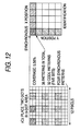
- FIG. 12 shows an example of code blocks.
- FIG. 12 also shows use of the unit code patterns in the 9 C 2 system. That is, the 36 kinds of unit code patterns are distributed into four patterns used as synchronous patterns and 32 patterns used as information patterns, for example. The patterns are placed in accordance with a layout.
- FIG. 12 such a layout is adopted that 25 areas (blocks), each where three dots by three dots can be placed, are arranged as five blocks by five blocks.
- a synchronous pattern is placed in the upper left one block of the 25 blocks.
- Information patterns representing X-direction position information are placed in the four blocks to the right of the synchronous pattern.
- Information patterns representing Y-direction position information are placed in the four blocks below the synchronous pattern.
- information patterns representing identification information of a sheet of paper or a document printed on the sheet of paper are placed in the 16 blocks surrounded by the information patterns representing the position information.
- FIG. 13 shows layout examples where the area in which dots can be placed is a square.
- FIG. 13A shows a unit code pattern in the 9 C 3 system as a unit code pattern example where the area in which dots can be placed is a square.
- FIGS. 13B to 13E show layouts of code blocks.
- FIGS. 13B and 13C shows a layout of placement of a synchronous pattern and information patterns indicating X position information, Y position information, and identification information like the layout in FIG. 12 .
- 36 blocks six blocks by six blocks
- 16 blocks four blocks by four blocks
- the both differ in code block size.
- FIGS. 13D and 13E shows a layout where information patterns indicating position information are not placed although a synchronous pattern and information patterns indicating identification information are placed.
- 25 blocks five blocks by five blocks
- 36 blocks six blocks by six blocks
- the two layouts different in size are provided.
- FIG. 14 shows layout examples where the area in which dots can be placed is a rectangle.
- FIG. 14A shows a unit code pattern in the 12 C 4 system as a unit code pattern example where the area in which dots can be placed is a rectangle.
- FIGS. 14B to 14E show layouts of code blocks.
- FIG. 14B shows a layout of placement of a synchronous pattern and information patterns indicating X position information, Y position information, and identification information like the layout in FIG. 12 .
- 20 blocks four blocks by five blocks are arranged.
- FIGS. 14C and 14D shows a layout where information patterns indicating position information are not placed although a synchronous pattern and information patterns indicating identification information are placed.
- 20 blocks four blocks by five blocks
- 30 blocks five blocks by six blocks
- the two layouts different in size are provided.
- FIGS. 13 and 14 are shown by way of example and any other layout may be adopted.
- such a layout may be used where only information patterns indicating position information are placed and no information patterns indicating identification information are placed.
- the code blocks having such a layout are used as basic units and are placed on the entire sheet of paper periodically.
- the position information may be represented in M sequences (maximum length sequences) over the length and the width of the sheet of paper as described later.
- the identification information may be coded with any of several methods.
- RS coding is adopted because RS coding is a multilevel coding method. In this case, block representation can be made to correspond to multilevel values of RS code. Of course, any other coding method may also be used.
- FIG. 15 is a block diagram to show a configuration example of the image generation apparatus 10 .
- the image generation apparatus 10 includes an identification code generation section 11 , a position code generation section 12 , an additional code generation section 13 , a block combining section 14 , a pattern image storage section 15 , and a code image generation section 16 .
- the identification code generation section 11 generates an identification code by coding identification information of a sheet of paper or a document printed on the sheet of paper.
- the identification code generation section 11 includes a block dividing section 11 a and an RS coding section 11 b.
- the block dividing section 11 a divides a bit string forming the identification information into plural blocks in order to perform RS coding. For example, to use information patterns capable of representing five-bit information in the 9 C 2 system, 60-bit identification information is divided into 12 blocks each having five bits in a block length.
- the RS coding section 11 b performs RS coding for the divided blocks and adds a redundant block for error correction. For example, if it is assumed that RS code capable of correcting an error of two blocks is adopted in this example, the code length becomes 16 blocks.
- the exemplary embodiment assumes that the identification code generation section 11 codes the identification information with the m C n system corresponding to predetermined m and n.
- the position code generation section 12 generates a position code by coding position information indicating each coordinate position on a sheet of paper.
- the position code generation section 12 includes an M-sequence coding section 12 a and a block dividing section 12 b.
- the M-sequence coding section 12 a codes the position information using M sequences. For example, an order of the M sequences is obtained from a length of the position information to be coded, and the M sequences are dynamically generated. Thereby, the position code is generated. However, if the length of the position information to be coded is previously known, the M sequences maybe stored in memory, etc., of the image generation apparatus 10 and when an image is generated, the M sequences may be read.
- the next cycle starts at the third bit of the M sequences and the next cycle starts at the fourth bit. Further, the fifth cycle starts at the fifth bit and matches the first cycle. Therefore, if the four cycles of the M sequences are cut out every four bits, 4095 code patterns can be covered. Since the M sequences are 12 orders, three consecutive code patterns do not match consecutive code patterns at any other position. Then, if three code patterns are read at the reading time, decoding is possible, but information is represented in four blocks considering an error.
- the exemplary embodiment assumes that the position code generation section 12 codes position information using the m C n system corresponding to predetermined m and n.
- the identification code generation section 11 the position code generation section 12 and the additional code generation section 13 are provided as an example of an acquisition unit that acquires information to be embedded in each of plural partitions on a recording medium.
- the term “partition” may mean a code block, for example.
- the additional code generation section 13 encodes additional information to be embedded in the recording medium in addition to the identification information and the position information, to generate an additional code.
- the additional information is not limited.
- information for restricting reading of the identification information and/or the position information from the recording medium, information representing the copyright holder of the image formed on the recording medium, or the like may be used as additional information.
- the block combining section 14 places the identification code generated by the identification code generation section 11 , the position code generated by the position code generation section 12 , and a synchronous code that controls reading of the identification code and the position code two-dimensionally, so as to generate a two-dimensional code array.
- the term “synchronous code” may mean a code corresponding to the synchronous pattern.
- the pattern image storage section 15 stores unit code patterns in the m C n system shown in FIGS. 1 to 8 , for example.
- a pattern value for uniquely identifying each unit code pattern is added to the unit code pattern.
- pattern values of 0 to 35 are added to the unit code patterns in the 9 C 2 system. They correspond to the code values in the two-dimensional code array generated by the block combining section 14 . That is, each unit code pattern is uniquely identified from the code value and is selected.
- the pattern image storage section 15 may store at least the unit code patterns in the m C n system corresponding to predetermined m and n.
- the code image generation section 16 refers to the two-dimensional code array generated by the block combining section 14 , selects the unit code pattern corresponding to each code value, and generates a code image.
- the code image generation section 16 is provided as an example of a generation unit that generates an image in which a pattern image representing information and a pattern image controlling reading of that pattern image are arranged in each of plural partitions.
- the code image is passed to an image formation section (not shown), which then forms the code image on a sheet of paper.
- the image formation section may form a superposition image with the document image of an electronic document and the code image superposed on each other on the sheet of paper.
- the correspondence between the positions on the electronic document and the positions on the sheet of paper may be managed so that written data with an electronic pen on the sheet of paper is reflected on the appropriate positions on the electronic document.
- the image formation section forms the code image in K toner (infrared absorption toner containing carbon) or special toner using electrophotography, for example.
- invisible toner having the maximum absorption rate being 7% or less in a visible light region (400 nm to 700 nm) and the absorption rate being 30% or more in a near-infrared region (800 nm to 1000 nm) is shown as the special toner.
- the terms “visible” and “invisible” do not relate to whether or not visual recognition can be made.
- the terms “visible” and “invisible” are distinguished from each other depending on whether or not an image formed on a printed medium cab be recognized according to the presence or absence of color reproduction caused by absorption of a specific wavelength in the visible light region. If it is hard to recognize by the eye of a human being although there is some reproduction caused by absorption of a specific wavelength in the visible light region, the term “invisible” is also applied.
- a CPU 91 (see FIG. 32 ) of the image generation apparatus 10 reads a program for implementing the block dividing section 11 a , the RS coding section 11 b , the M-sequence coding section 12 a , the block dividing section 12 b , the block combining section 14 , and the code image generation section 16 , for example, into main memory 92 (see FIG. 32 ) from a magnetic disk unit 93 (see FIG. 32 ) for execution.
- the pattern image storage section 15 may be implemented using the magnetic disk unit 93 (see FIG. 32 ), for example.
- the program and data stored in the magnetic disk unit 93 may be loaded from a recording medium such as a CD or may be downloaded through communication means of the Internet, etc.
- parameters for controlling the operation are given. First, the parameters will be described.
- the parameters may be externally input by a user or may be calculated by the image generation apparatus 10 based on an amount of information to be represented, a size of a sheet of paper in which information is to be embedded, etc., for example.
- first to third parameters may be employed.
- the first parameter is a size of a code block.
- the exemplary embodiment allows a code block to have various sizes as shown in FIGS. 12 to 14D .
- the size is specified by the first parameter.
- the first parameter includes the number of blocks in the X direction of the code block and the number of blocks in the Y direction.
- the former is expressed as Bx and the latter as By.
- the second parameter is a kind of pattern placed in each block in the code block. That is, the second parameter specifies an information pattern representing what information is to be placed at which position using a synchronous pattern as a reference.
- C (0, 0) “synchronous”
- a “synchronous pattern” may be expressed as “synchronous”
- an “information pattern representing X position information” may be expressed as “X position”
- an “information pattern representing Y position information” may be expressed as “Y position”
- an “information pattern representing identification information” may be expressed as “identification.”
- the third parameter is a method of dividing information patterns. If the number of synchronous patterns is the same in the same m C n system, there may be plural methods of dividing information patterns, that is, there may be plural methods of grouping information patterns as shown in FIG. 10 . For example, the case where five sets of synchronous patterns are provided in the 9 C 3 system is considered. In this case, to group information patterns, available is either a first method of grouping 64 kinds of information patterns as a single group (distribution No. 1 ) or a second method of classifying 64 kinds of information patterns into two groups each made up of 32 kinds of information patterns (distribution No. 2 ). Although not shown in FIG.
- the exemplary embodiment makes it possible to know which method of dividing information patterns is adopted by information as to which set the used synchronous pattern belongs to among the plural sets of synchronous patterns.
- the third parameter may specify a distribution No. in an m C n system used in generating an image. In this case, the image generation apparatus 10 finds the number of divisions D based on the specified distribution No.
- any parameters may be used as the first and second parameters so long as the parameters specify a layout of a code block.
- any parameter may be used as the third parameter so long as the parameter relates to a method of selecting information patterns from among plural information pattern groups.
- Any parameter relating to placement of information patterns may be adopted in addition to specifying of a layout of a code block and selecting of information patterns from among plural information pattern groups.
- the parameters are stored in a parameter storage section (not shown) such as a memory and the sections of the image generation apparatus 10 operate based on the parameters stored in the parameter storage section.
- the identification code generation section 11 finds the number of blocks to store an identification code based on a size of a code block specified by the first parameter and a kind of a pattern placed in each block specified by the second parameter.
- the block dividing section 11 a and the RS coding section 11 b perform the block dividing process and the RS coding so that the number of blocks becomes the found number of blocks finally. For example, if the parameters indicate the layout shown in FIG. 13B , 25 blocks are provided per code block.
- the position code generation section 12 finds the number of blocks to store a position code based on the code block size of the first parameter and the type of pattern placed in each block of the second parameter.
- the M-sequence coding section 12 a and the block dividing section 12 b perform the M sequences coding and the block dividing process so that the number of blocks becomes the found number of blocks finally. For example, if the parameters indicate the layout shown in FIG. 13B , five blocks are provided as the X position information in one code block.
- the additional code generation section 13 divides an additional code into plural blocks based on the size of the code block specified by the first parameter.
- A(E, F) ((E, F) (1, 0), (2, 0), . . . , (Bx, 0), (0, 1), (1, 1), (2, 1), . . . , (Bx, 1), . . . , (0, By), (1, By), (2, By), . . . , (Bx, By)).
- the number of divisions D is found from the method of dividing information patterns specified by the third parameter and the number of pieces of information assigned to each block is determined based on the number of divisions D.
- correspondence information that associates each set of synchronous patterns with a corresponding rule that relates to placement of information patterns and is employed when synchronous patterns belonging to each set are used is stored in a correspondence information storage section (not shown) such as a memory.
- the rule relating to placement of information patterns may be represented using the first to third parameters in combination, for example.
- the case where the sets of synchronous patterns and the combinations of the first and second parameters are stored in association with each other is considered by way of example. For example, it is assumed that five sets of synchronous patterns are provided in the 9 C 3 system as shown in FIG. 11 , the synchronous pattern group Q 1 may be associated with the layout shown in FIG. 13B , the synchronous pattern group Q 2 may be associated with the layout shown in FIG.
- the synchronous pattern group Q 3 may be associated with the layout shown in FIG. 13D
- the synchronous pattern group Q 4 may be associated with the layout shown in FIG. 13E . If they are thus associated, one of the five sets of synchronous patterns is not associated with any layout. This one may be associated with another layout (not shown) or may be associated with no layout.
- sets of synchronous patterns to be associated with the combinations may be short.
- particularly necessary combinations may be selected as many as the number of sets of synchronous patterns from among many combinations and may be associated with the sets of synchronous patterns.
- FIG. 16 is a flowchart to show the operation of the block combining section 14 .
- the operation of the block combining section 14 is applied to one code block.
- the block combining section 14 performs a similar process for the code blocks placed on the entire sheet of paper.
- the block combining section 14 assigns “0” to E and F (step 101 ).
- E is a counter that counts the number of blocks in the X direction
- F is a counter that counts the number of blocks in the Y direction.
- the block combining section 14 refers to the parameters stored in the parameter storage section and determines as to whether or not C (E, F) is “synchronous” (step 102 ).
- the block combining section 14 determines a set of synchronous patterns corresponding to the parameters by referring to the correspondence information storage section. Then, the block combining section 14 places a synchronous code corresponding to the synchronous patterns belong to the determined set, on a two-dimensional code array (step 103 ).
- the block combining section 14 determines that C (E, F) is not “synchronous,” namely, if the block combining section 14 determines that C (E, F) is any of “X position,” “Y position,” and “identification,” the block combining section 14 determines an information pattern group corresponding to a value stored in A (E, F) given by the additional code generation section 13 .
- the block combining section 14 selects an information pattern representing the information to be placed from among the information pattern groups and places a code corresponding to the selected information pattern on the two-dimensional code array (step 104 ).
- FIG. 17 is a block diagram to show the configuration example of the image processing apparatus 20 .
- the image processing apparatus 20 includes an image reading section 21 , a noise removal section 22 , a dot image detection section 23 , a dot array generation section 24 , a block detection section 25 , a synchronous code detection section 26 , an identification information acquisition section 27 , and a position information acquisition section 28 .
- the image reading section 21 reads a code image printed on a sheet of paper with an imaging device such as a CCD (Charge Coupled Device) or a CMOS (Complementary Metal Oxide Semiconductor).
- an imaging device such as a CCD (Charge Coupled Device) or a CMOS (Complementary Metal Oxide Semiconductor).
- the image reading section 21 is provided as an example of an image acquisition unit that acquires an image containing a pattern image representing information and a pattern image that controls reading of that pattern image from a recording medium.
- the noise removal section 22 removes noise contained in the read image.
- the noise includes noise occurring due to variations in sensitivity of the imaging device or an electronic circuit, for example.
- a blurring process and/or a sharpening process such as unsharp masking may be applied.
- the dot image detection section 23 detects each dot with noise removed. That is, the dot image detection section 23 determines positions where dots are formed. To detect dots, first the dot image detection section 23 separates a dot image portion and other background image portions by performing a binarization process, and detects the positions of the dots from respective positions of binarized images. At this time, the binarized images may contain a large number of noise components. Therefore, the dot image detection section 23 may perform a filtering process to determine dots, based on an area and a shape of the binarized images.
- the dot array generation section 24 refers to the positions of the detected dots and generates a dot array. That is, on a two-dimensional array, for example, “1” is stored at a position where a dot exists and “0” is stored at a position where no dot exists. Thereby, the dots detected as images are replaced with digital data.
- the two-dimensional array is output as a dot array.
- the dot array generation section 24 determines m and n in an m C n system that are used in coding, based on a ratio between all the elements of the dot array and the elements where “1” is recorded, for example.
- the block detection section 25 detects a block corresponding to a unit code pattern in a code block on the dot array. That is, the block detection section 25 moves a rectangular block separator having the same size as the unit code pattern appropriately on the dot array, adopts a position where the numbers of dots in the blocks becomes uniform as a correct block separation position, and generates a code array storing the pattern values in each block.
- the block detection section 25 determines m and n in the m C n system that are used in coding, based on a size of each block and the number of dots in each block when the numbers of dots in the blocks becomes uniform.
- the synchronous code detection section 26 refers to a kind of unit code pattern detected from the dot array and detects a synchronous code. If the unit code pattern is a square, there is a possibility that the unit code pattern may be rotated in 90-degree units. Then, the synchronous code detection section 26 detects and corrects the orientation based on which of the four kinds of synchronous patterns the detected synchronous code corresponds to. If the unit code pattern is a rectangle, there is a possibility that the unit code pattern maybe rotated in 180-degree units. Then, the synchronous code detection section 26 detects and corrects the orientation based on which of the two kinds of synchronous patterns the detected synchronous code corresponds to.
- the identification information acquisition section 27 acquires identification information from the code array based on the synchronous code detected by the synchronous code detection section 26 .
- the identification information acquisition section 27 includes an identification code detection section 27 a and an identification code decoding section 27 b.
- the identification code detection section 27 a detects an identification code from the code array whose orientation is corrected, with using the position of the synchronous code as a reference.
- the identification code decoding section 27 b decodes the identification code using the same parameters as the parameters (the number of blocks, etc.,) used in the coding processing of RS code previously described with reference to FIG. 15 , and outputs identification information.
- the position information acquisition section 28 acquires position information from the code array based on the synchronous code detected by the synchronous code detection section 26 .
- the position information acquisition section 28 includes a position code detection section 28 a and a position code decoding section 28 b.
- the position code detection section 28 a detects a position code from the code array whose orientation is corrected, with using the position of the synchronous code as a reference.
- the position code decoding section 28 b extracts partial sequences of M sequences from the position code detected by the position code detection section 28 a , refers to the position of the partial sequences in the M sequences used in generating the image, and outputs a correction value of the position of the partial sequences, which is corrected with an offset based on the synchronous code, as position information.
- the reason why the offset correction is made at the time is that a synchronous code is placed between position codes.
- the synchronous code detection section 26 , the identification information acquisition section 27 , and the position information acquisition section 28 are provided as an example of an information acquisition unit that determines a pattern image group to which a pattern image that controls reading of a pattern image representing information belongs, and that acquires information based on a rule associated with the pattern image group.
- a CPU 91 (see FIG. 32 ) of the image processing apparatus 20 reads a program for implementing the noise removal section 22 , the dot image detection section 23 , the dot array generation section 24 , the block detection section 25 , the synchronous code detection section 26 , the identification code detection section 27 a , the identification code decoding section 27 b , the position code detection section 28 a , and the position code decoding section 28 b , for example, into main memory 92 (see FIG. 32 ) from a magnetic disk unit 93 (see FIG. 32 ) for execution.
- the program and data stored in the magnetic disk unit 93 may be loaded from a recording medium such as a CD or may be downloaded through communication means of the Internet, etc.
- the coded image is read and then the values of m and n are determined.
- the value of n is determined.
- the value of n is determined in a first type.
- the value of m is unknown although the value of m is known, the value of n is determined.
- the value of m is determined in a second type.
- the value of m is determined in a third type.
- both the values of m and n are unknown, both the values of m and n are determined.
- To determine the coding system there are a determination method based on the dot density and a determination method using a block separator.
- Determination based on the dot density is made as a process after the dot array generation section 24 shown in FIG. 17 generates a dot array. That is, the dot array generation section 24 generates a dot array in which “1” is stored at the position where a dot exists and “0” is stored at the position where no dot exists, for example, as a precondition of this process.
- a dot density table as shown in FIG. 18 is stored in a memory that may be referred to by the dot array generation section 24 .
- the dot density table stores a dot density when a code image is generated in each m C n system in a cell corresponding to the value of m and the value of n.
- the table indicates that the dot density when the 9 C 2 system is used is “0.222” and that the dot density when the 9 C 3 system is used is “0.333.”
- m stored in the G th row from the top will be expressed as m (G). This is because m is not necessarily equal to G in the G th row as m needs to be at least the product of two integers.
- every integer satisfying 1 ⁇ n ⁇ m may be used as n.
- n H in the H th column from the left.
- the dot density stored in the G th row, H th column cell is expressed as DTBL (G, H) and the maximum value of m in this dot density table is expressed as m max .
- the dot density table shown in FIG. 18 is adopted as an example of density information that associates a unit image density when each unit image is formed by selecting n positions from among m positions, with the values of m and n.
- the dot array generation section 24 compares the dot density in the input image with each dot density in the dot density table in FIG. 18 , and estimates the values of m and n.
- FIG. 19 is a flowchart to show the operation of the dot array generation section 24 when determining a coding system.
- the dot array generation section 24 detects an inclination angle of an input image based on an inclination between the two nearest dots and superposes lattices which have the inclination and which have the lattice spacing equaling the spacing between the nearest dots, to thereby generate a dot array.
- this process is excluded from the flowchart.
- the dot array generation section 24 first counts the number of all elements AD in the dot array and the number of elements ND where “1,” for example, indicating that a dot exists is stored in the dot array.
- the dot array generation section 24 calculates ND/AD to calculate a ratio of the dots in the entire image.
- the dot array generation section 24 assigns this ratio to Din as a dot density of the input image (step 201 ).
- the dot array generation section 24 assigns “1” to counters G and H to identify each cell of the dot density table and assigns “0” to a counter Z that counts the number of the candidates for combinations of m and n in the m C n system (step 202 ).
- the dot array generation section 24 refers to the G th row, Hth column cell of the dot density table and assigns the dot density DTBL (G, H) in the cell to Dreg (step 203 ). Then, the dot array generation section 24 determines as to whether or not a difference between Din found at step 201 and Dreg found at step 204 is smaller than a predetermined threshold value TD (step 204 ).
- the dot array generation section 24 recognizes that the combination of m(G) and H at this time is a candidate for the combination of m and n to be found. Then, the dot array generation section 24 first adds “1” to Z. The dot array generation section 24 assigns m(G) to a variable ms (Z) to store the candidate for m, and assigns H to a variable ns (Z) to store the candidate for n. Further, the dot array generation section 24 assigns Z to a variable Zmax to store the number of the candidates for the combinations of m and n (step 205 ). The process goes to step 206 .
- Determination using a block separator is made together with block detection by the block detection section 25 shown in FIG. 17 .
- FIG. 20 is a flowchart to show the operation of the block detection section 25 when determining a coding system. It is assumed that m dots in a unit code pattern are placed as mx dots in width by my dots in height.
- the block detection section 25 first superposes a block separator including blocks each having a size of mx ⁇ my on the dot array generated by the dot array generation section 24 (step 221 ).
- the block detection section 25 assigns “0” to counters I and J and assigns HV to a variable MinV (step 222 ) .
- the counters I and J count a move distance from the initial position of the block separator.
- the block separator is moved every line of an image and the counters I and J count the number of moved lines.
- the position where the block separation is superposed on data may be an arbitrary position. This is because even if a reading position shifts, identification information is copied repeatedly and thus is acquired by interpolation.
- the block separator always contains blocks representing X position information and Y position information.
- MinV stores a minimum value of block-to-block variance of the number of dots detected in the respective blocks.
- HV means a sufficiently large value with respect to the variance.
- the block detection section 25 moves the block separator I in the X direction and J in the Y direction (step 223 ). In the initial state, I and J are equal to “0.” Therefore, the block separator does not move.
- the block detection section 25 counts the number of dots contained in each block of the block separator, assigns variance of the numbers of dots among all blocks to Var(I, J), and assigns the average of the numbers of dots in all blocks to Ave(I, J) (step 224 ).
- the block detection section 25 compares Var(I, J) with MinV (step 225 ). Since the initial value of MinV is HV, Var(I, J) is smaller than MinV in the first comparison.
- the block detection section 25 assigns the value of Var(I, J) to MinV.
- the block detection section 25 also assigns the value of I to a variable FX that represents displacement of the block separator in the X direction, and assigns the value of J to a variable FY that represents displacement of the block separator in the Y direction. Further, the block detection section 25 assigns the value obtained by rounding off Ave(I, J) to the nearest integer, to n (step 226 ). Then, the process goes to step 227 .
- the block detection section 25 compares the stored MinV with a threshold value TV (step 231 ).
- the threshold value TV is a threshold value to prevent variance of the numbers of dots among all blocks from becoming too large.
- the block detection section 25 fixes the block separator to the position of FX, FY, detects a unit code pattern in each block of the block separator at the position of FX, FY, and converts the unit code pattern into the corresponding pattern value.
- Each pattern value is stored in a memory as P (X, Y) together with the variables X and Y that identify each block. If the detected unit code pattern cannot be converted into the corresponding pattern value, “ ⁇ 1” is stored in place of the pattern value (step 232 ).
- the block detection section 25 determines that image noise is large and that it is impossible to decode, and outputs information indicating that it is impossible to decode (step 233 ).
- FIG. 21 shows an example of the case where the values of m and n are known.
- the block detection section 25 acquires a dot array from the dot array generation section 24 .
- the size of the dot array to be acquired is preset, but corresponds to any selected area of an image. Therefore, the position of a block separator is unknown.
- the block detection section 25 moves the block separator and counts the number of dots in each block of the block separator. That is, the block detection section 25 performs similar operations in the initial position, in the position with one dot moved in the right direction, and in the position with two dots moved in the right direction. For each of these positions, the block detection section 25 performs similar operations in the initial position, in the position with one dot moved in the lower direction, and in the position with two dots moved in the lower direction.
- the block detection section 25 determines that this position is the correct separation position.
- the block detection section 25 may assign the number of blocks in which the number of dots is equal to n to a variable IB(I, J) at step 224 in FIG. 20 , assign the maximum value of IB(I, J) to MaxBN at steps 225 to 230 , and determine as to whether or not MaxBN is larger than a threshold value TB at step 213 .
- the dot array generation section 24 performs the process shown in FIG. 19 . That is, the dot array generation section 24 calculates the ratio between the total number of elements of the input dot array and the number of actually placed dots. Then, the dot array generation section 24 determines a combination of m and n corresponding to a dot density close to the calculated ratio, from the dot density table shown in FIG. 18 .
- the difference combinations of m and n may be close to each other in the dot density.
- the dot density when the 9 C 2 system is used and the dot density when the 12 C 3 system is used are close values.
- theses coding systems may become candidates for the coding system to be found.
- FIG. 23 shows the state at this time.
- the dot density when the 9 C 3 system is used and the dot density when the 12 C 4 system is used are the same values, and the process shown in FIG. 19 cannot determine which of the dot densities the actual dot density is.
- FIG. 24 shows the state at this time.
- the number of dots in every block becomes “4” and variance of the numbers of dots becomes “0” at the position moved one dot to the right and moved two dots to the bottom from the initial position of the block separator. Therefore, the block detection section 25 determines that this position is the correct separation position of the block separator.
- FIG. 26 shows an example of the case where the orientation of the input image is rotated 90 degrees.
- the image processing apparatus 20 stores the same correspondence information that is referred to in generating the image in the correspondence information storage section (not shown) such as a memory. That is, the correspondence relation between each set of synchronous patterns and a rule which relates to placement of information patterns and which is used when the synchronous patterns belonging to each set may be referred to, if necessary.
- FIG. 28 is a flowchart to show the operation of the synchronous code detection section 26 at this time.
- the maximum value of the number of blocks in the X direction contained in a code block and the maximum value of the number of blocks in the Y direction are expressed as Bmax.
- the synchronous code detection section 26 first assigns “0” to K and L (step 241 ).
- K is a counter indicating the number of blocks in the X direction
- L is a counter indicating the number of blocks in the Y direction.
- the synchronous code detection section 26 determines as to whether or not a code corresponding to a synchronous pattern is stored in P(K, L) (step 242 ). For example, to use the pattern shown in FIG. 11 , the synchronous code detection section 26 determines as to whether or not a pattern value of a synchronous pattern that belongs to any of the synchronous pattern groups Q 1 to Q 5 is stored in P(K, L).
- the synchronous code detection section 26 determines that a code corresponding to a synchronous pattern is stored in P(K, L) at step 242 , the synchronous code detection section 26 performs the following process.
- the synchronous code detection section 26 rotates the code array of Bmax ⁇ Bmax and finds SyncX, SyncY, ShiftX, and ShiftY (step 248 ).
- SyncX is the X coordinate of a position where the synchronous pattern is placed in the code array of Bmax ⁇ Bmax.
- SyncY is the Y coordinate of the position where the synchronous pattern is placed in the code array of Bmax ⁇ Bmax.
- ShiftX is the move distance of the block separator in the X direction.
- ShiftY is the move distance of the block separator in the Y direction.
- the synchronous code detection section 26 detects the synchronous pattern having the pattern value 32 , the synchronous code detection section 26 does not rotate the code array and assign K to SyncX, L to SyncY, FX to ShiftX, and FY to ShiftY.
- the synchronous code detection section 26 detects the synchronous pattern having the pattern value 33 , the synchronous code detection section 26 rotates the code array left 90 degrees and assigns L to SyncX, Bmax ⁇ 1 ⁇ K to SyncY, FY to ShiftX, and 2 ⁇ FX to ShiftY.
- the synchronous code detection section 26 detects the synchronous pattern having the pattern value 34 , the synchronous code detection section 26 rotates the code array 180 degrees and assigns Bmax ⁇ 1 ⁇ K to SyncX, Bmax ⁇ 1 ⁇ L to SyncY, 2 ⁇ FX to ShiftX, and 2 ⁇ FY to ShiftY.
- the synchronous code detection section 26 detects the synchronous pattern having the pattern value 35 , the synchronous code detection section 26 rotates the code array left 270 degrees and assigns Bmax ⁇ 1 ⁇ L to SyncX, K to SyncY, 2 ⁇ FY to ShiftX, and FX to ShiftY.
- the synchronous code detection section 26 detects the synchronous pattern having the pattern value 64 , the synchronous code detection section 26 does not rotate the code array and assigns K to SyncX, L to SyncY, FX to ShiftX, and FY to ShiftY.
- the synchronous code detection section 26 detects the synchronous pattern having the pattern value 65 , the synchronous code detection section 26 rotates the code array 180 degrees and assigns Bmax ⁇ 1 ⁇ K to SyncX, Bmax ⁇ 1 ⁇ L to SyncY, 3 ⁇ FX to ShiftX, and 2 ⁇ FY to ShiftY.
- the synchronous code detection section 26 determines a set to which the detected synchronous pattern belongs (step 249 ). Taking the case shown in FIG. 11 as an example, the synchronous code detection section 26 determines which of the synchronous pattern groups Q 1 to Q 5 the detected synchronous pattern belongs to.
- the synchronous code detection section 26 determines the distribution No. and finds the number of divisions D corresponding to the distribution No. (step 252 ). For example, it is assumed that pattern distribution methods are defined as shown in FIG. 10 . In this case, if it is determined in the process shown in FIG. 19 or 20 that the coding system is the 9 C 2 system or the 12 C 2 system, the synchronous code detection section 26 refers to the parameter stored in the parameter storage section and determines which of “1,” “2,” and “3” the distribution No. is. For example, if it is determined that the distribution No. is “2” in the 9 C 2 system, it is found that the number of divisions D is “2.” If it is determined in the process shown in FIG.
- the synchronous code detection section 26 refers to the parameter stored in the parameter storage section and determines which of “1” and “2” the distribution No. is. For example, if it is determined that the distribution No. is “2” in the 9 C 3 system, it is found that the number of divisions D is “2.”
- an embedded additional code may be superposed on an identification code and a position code is also detected in the operation. Therefore, these processes will also be described.
- FIG. 29 is a flowchart to show the operation of the identification code detection section 27 a at this time.
- the identification code detection section 27 a first assigns “0” to counters S and T that identify each block in a code block of Bx ⁇ By, and assigns “0” to a counter EN that counts the number of blocks determined as an error among blocks indicating identification information (step 261 ).
- S is a counter that indicates the number of blocks in the X direction
- T is a counter that indicates the number of blocks in the Y direction.
- the identification code detection section 27 a determines as to whether or not the block identified by S and T contains a synchronous code (step 262 ).
- the process starts from the row and the column where a synchronous code is placed. That is, it is determined as to whether or not the block whose X coordinate is (SyncX+S) (modBx) and whose Y coordinate is (SyncY+T) (modBy) contains a synchronous code. Specifically, it is determined as to whether or not C((SyncX+S) (modBx), (SyncY+T) (modBy)) is “synchronous.”.
- the process goes to step 269 .
- the identification code detection section 27 a extracts the corresponding pattern value from the code array generated by the block detection section 25 .
- the identification code detection section 27 a extracts the pattern value stored in P ((SyncX+S) (modBx), (SyncY+T) (modBy)) and assigns the pattern value to PS (S, T) (step 263 ).
- the identification code detection section 27 a determines as to whether or not the pattern value stored in PS(S, T) is smaller than “0” (step 264 ).
- the identification code detection section 27 a adds “1” to the counter EN for counting the number of blocks determined as an error (step 265 ).
- the identification code detection section 27 a determines a group to which the information pattern having the pattern value stored in PS(S, T) belongs, and stores a value associated with the group in A(S, T) (step 266 ). The identification code detection section 27 a determines as to whether or not an identification code is placed in the block (step 267 ).
- the identification code detection section 27 a assigns the value stored in PS(S, T) to ID(S, T) to store the identification code (step 268 ), and goes to step 269 . If an identification code is not placed, a position code is placed in the block. Thus, the identification code detection section 27 a goes to step 269 without assigning to ID(S, T).
- the identification code detection section 27 a determines as to whether or not the value of the counter EN that counts the number of errors is larger than a threshold value TN (step 273 ).
- the threshold value TN indicates allowable number of errors per code block.
- a uniform value may be preset without considering the layouts of the code blocks or the number of blocks where an identification code is placed in each code block, multiplied by a given ratio may be adopted.
- the identification code decoding section 27 b decodes the identification code stored in ID (S, T) and acquires identification information (step 274 ). The identification code decoding section 27 b also decodes the additional code stored in A(S, T) and acquires additional information (step 275 ).
- N/A (not applicable) is output as identification information and additional information (step 276 ).
- FIG. 30 is a flowchart to show the operation of the position code detection section 28 a at this time.
- the position code detection section 28 a first assigns “0” to a counter U that counts the number of blocks in the X direction and assigns “0” to a counter EM that counts the number of blocks determined as an error among blocks indicating position information (step 281 ).
- the position code detection section 28 a determines as to whether or not the block determined by U contains an X position code (step 282 ). Specifically, it is determined as to whether or not C(U, SyncY) is “X position.”
- step 286 If it is not determined that a position code is placed in the block, the process goes to step 286 .
- the position code detection section 28 a extracts a corresponding pattern value from the code array generated by the block detection section 25 .
- the position code detection section 28 a extracts a pattern value stored in P(U, SyncY) and assigns the pattern value to XA(U) (step 283 ).
- the position code detection section 28 a determines as to whether or not the pattern value stored in XA(U) is smaller than “0” (step 284 ).
- step 286 If the pattern value is not smaller than “0,” the process goes to step 286 .
- the position code detection section 28 a adds “1” to the counter EM for counting the number of blocks determined an error (step 285 ) and goes to step 286 .
- the position code detection section 28 a determines as to whether or not the value of the counter EM that counts the number of errors is larger than a threshold value TM (step 288 ).
- the threshold value TM indicates allowable number of errors per code block.
- a uniform value may be preset without considering the layouts of the code blocks or the number of blocks where a position code is placed in each code block, multiplied by a given ratio may be adopted.
- the position code detection section 28 a acquires X position information from XA(U) and ShiftX (step 289 ). In this case, since no pattern value is stored in XA (SyncX), it is necessary to remove it and join the remaining XA(U).
- N/A (not applicable) is output as position information (step 290 ).
- the operation for detecting a Y position code and acquiring Y position information is also similar to the operation described above and therefore will not be described again in detail.
- the image processing in the exemplary embodiment is performed on the assumption that the values of m and n are unknown, and the values of m and n are determined before information coded in the m C n system is acquired.
- information may be acquired according to a similar method in a state where the values of m and n are already determined.
- FIG. 31 is a drawing to show the mechanism of the electronic pen 60 .
- the electronic pen 60 includes a control circuit 61 for controlling the operation of the whole pen.
- the control circuit 61 includes an image processing section 61 a for processing a code image detected from an input image and a data processing section 61 b for extracting identification information and position information from the processing result of the image processing section 61 a.
- a pressure sensor 62 for detecting the writing operation with the electronic pen 60 according to the pressure applied to a pen tip 69 is connected to the control circuit 61 .
- An infrared LED 63 for applying infrared radiation onto a medium and an infrared CMOS 64 for inputting an image are also connected to the control circuit 61 .
- information memory 65 for storing identification information and position information
- a communication circuit 66 for communicating with an external unit a battery 67 for driving the pen
- pen ID memory 68 for storing identification information of the pen (pen ID).
- the image reading section 21 shown in FIG. 17 is implemented as the infrared CMOS 64 in FIG. 31 , for example.
- the noise removal section 22 , the dot image detection section 23 , and the dot array generation section 24 shown in FIG. 17 are implemented as the image processing section 61 a in FIG. 31 , for example.
- the block detection section 25 , the synchronous code detection section 26 , the identification information acquisition section 27 , and the position information acquisition section 28 shown in FIG. 17 are implemented as the data processing section 61 b in FIG. 31 , for example.
- the image generation apparatus 10 is implemented as a computer part of an image formation apparatus such as a server computer, a client computer, or a printer, for example.
- the image processing apparatus 20 is implemented not only as the electronic pen 60 , but also as a computer part of an image reader such as a scanner, for example. Then, each of the image generation apparatus 10 and the image processing apparatus 20 is implemented as a general computer 90 and the hardware configuration of the computer 90 will be described.
- FIG. 32 is a block diagram to show the hardware configuration of the computer 90 .
- the computer 90 includes a CPU (Central Processing Unit) 91 of computation means and main memory 92 and a magnetic disk unit (HDD: Hard Disk Drive) 93 of storage means.
- the CPU 91 executes OS (Operating System) and various software programs of applications, etc., and realizes the functions described above.
- the main memory 92 is a storage area for storing various software programs and data used for execution of the software
- the magnetic disk unit 93 is a storage area for storing input data to various software programs, output data from various software programs, and the like.
- the computer 90 further includes a communication I/F 94 for conducting external communications, a display mechanism 95 made up of video memory, a display, etc., and input devices 96 of a keyboard, a mouse, etc.
- the program for implementing the exemplary embodiment can be provided not only by communication means, but also by a recording medium such as a CD-ROM storing the program.
Landscapes
- Engineering & Computer Science (AREA)
- Physics & Mathematics (AREA)
- Theoretical Computer Science (AREA)
- General Physics & Mathematics (AREA)
- Electromagnetism (AREA)
- General Engineering & Computer Science (AREA)
- General Health & Medical Sciences (AREA)
- Toxicology (AREA)
- Artificial Intelligence (AREA)
- Computer Vision & Pattern Recognition (AREA)
- Health & Medical Sciences (AREA)
- Human Computer Interaction (AREA)
- Editing Of Facsimile Originals (AREA)
- Image Processing (AREA)
Abstract
Description
Claims (9)
Applications Claiming Priority (2)
| Application Number | Priority Date | Filing Date | Title |
|---|---|---|---|
| JP2006-295009 | 2006-10-30 | ||
| JP2006295009A JP2008113258A (en) | 2006-10-30 | 2006-10-30 | Image generating device, image processing apparatus, and program |
Publications (2)
| Publication Number | Publication Date |
|---|---|
| US20080101702A1 US20080101702A1 (en) | 2008-05-01 |
| US8019181B2 true US8019181B2 (en) | 2011-09-13 |
Family
ID=39330248
Family Applications (1)
| Application Number | Title | Priority Date | Filing Date |
|---|---|---|---|
| US11/785,330 Expired - Fee Related US8019181B2 (en) | 2006-10-30 | 2007-04-17 | Image generation apparatus, image processing apparatus, computer readable medium and computer data signal |
Country Status (2)
| Country | Link |
|---|---|
| US (1) | US8019181B2 (en) |
| JP (1) | JP2008113258A (en) |
Families Citing this family (6)
| Publication number | Priority date | Publication date | Assignee | Title |
|---|---|---|---|---|
| JP4556705B2 (en) * | 2005-02-28 | 2010-10-06 | 富士ゼロックス株式会社 | Two-dimensional coordinate identification apparatus, image forming apparatus, and two-dimensional coordinate identification method |
| JP5136302B2 (en) | 2008-03-27 | 2013-02-06 | 株式会社デンソーウェーブ | Two-dimensional code, two-dimensional code generation method, computer-readable program for displaying two-dimensional code, authentication method using two-dimensional code, and information providing method using two-dimensional code |
| JP5272986B2 (en) * | 2009-09-14 | 2013-08-28 | 富士ゼロックス株式会社 | Image processing apparatus and program |
| CN107122768A (en) * | 2017-05-31 | 2017-09-01 | 吉林大学 | A kind of three-dimensional pen type identification preprocess method |
| KR20220165865A (en) * | 2021-06-08 | 2022-12-16 | 삼성디스플레이 주식회사 | Display device and touch input system including the same |
| KR20230174330A (en) * | 2022-06-17 | 2023-12-28 | 삼성디스플레이 주식회사 | Display device and input system including the same |
Citations (22)
| Publication number | Priority date | Publication date | Assignee | Title |
|---|---|---|---|---|
| US4924078A (en) * | 1987-11-25 | 1990-05-08 | Sant Anselmo Carl | Identification symbol, system and method |
| JPH06231466A (en) | 1992-09-28 | 1994-08-19 | Olympus Optical Co Ltd | Dot code and information recording and reproducing system for recording and reproducing the same |
| US5548407A (en) * | 1992-05-22 | 1996-08-20 | Albrecht von Kienlin | Process for electronic processing of multi-colored continuous-tone images |
| EP0780790A2 (en) | 1995-12-21 | 1997-06-25 | Xerox Corporation | Tiled embedded data blocks |
| US5726435A (en) * | 1994-03-14 | 1998-03-10 | Nippondenso Co., Ltd. | Optically readable two-dimensional code and method and apparatus using the same |
| US5915042A (en) * | 1996-03-28 | 1999-06-22 | Oki Data Corporation | Coding and decoding methods and apparatus for compressing and expanding image data |
| US6052813A (en) | 1992-09-28 | 2000-04-18 | Olympus Optical Co., Ltd. | Dot code including a plurality of blocks wherein each of the blocks has a block address pattern representing an address of each of the blocks |
| JP2000293303A (en) | 1999-02-03 | 2000-10-20 | Ricoh Co Ltd | Coordinate input device, information processing system and medium |
| WO2001026033A1 (en) | 1999-10-01 | 2001-04-12 | Anoto Ab | Position determination - calculation |
| US6302329B1 (en) * | 1994-12-27 | 2001-10-16 | Sharp Kabushiki Kaisha | Method and apparatus for recording digital information in two-dimensional pattern, carrier of digital information recorded thereby, and a method and apparatus for decoding such digital information |
| US6432518B1 (en) | 1998-12-28 | 2002-08-13 | Ricoh Company, Ltd. | Erasable recording material capable of inputting additional information written thereon and information recording system and information recording method using the recording material |
| US6532301B1 (en) * | 1999-06-18 | 2003-03-11 | Microsoft Corporation | Object recognition with occurrence histograms |
| US20040085287A1 (en) | 2002-10-31 | 2004-05-06 | Microsoft Corporation | Decoding and error correction in 2-D arrays |
| US6857571B2 (en) * | 2000-06-30 | 2005-02-22 | Silverbrook Research Pty Ltd | Method for surface printing |
| US6859155B2 (en) * | 2000-10-19 | 2005-02-22 | Sony Corporation | Data processing device |
| JP2005092438A (en) | 2003-09-16 | 2005-04-07 | Casio Comput Co Ltd | Flat recording medium and coordinate reading method |
| JP2005235185A (en) | 2004-01-16 | 2005-09-02 | Microsoft Corp | Stroke localization by m-array decoding and fast image matching |
| US6985626B2 (en) * | 2001-03-27 | 2006-01-10 | Kabushiki Kaisha Toshiba | Pattern evaluation method, pattern evaluation system and computer-readable recorded medium |
| JP2006085679A (en) | 2004-08-16 | 2006-03-30 | Ricoh Co Ltd | Two-dimensional code pattern, two-dimensional code generating method, two-dimensional code generator and printing medium |
| US20060203314A1 (en) | 2005-03-14 | 2006-09-14 | Fuji Xerox Co., Ltd. | Image generating/reading apparatus and methods and storage media storing programs therefor |
| US7376289B2 (en) * | 2003-09-30 | 2008-05-20 | Matsushita Electric Industrial Co., Ltd. | Image processing method and image processing apparatus |
| US7852520B2 (en) * | 2006-03-30 | 2010-12-14 | Murata Kikai Kabushiki Kaisha | Scanner control device and scanner device |
-
2006
- 2006-10-30 JP JP2006295009A patent/JP2008113258A/en active Pending
-
2007
- 2007-04-17 US US11/785,330 patent/US8019181B2/en not_active Expired - Fee Related
Patent Citations (29)
| Publication number | Priority date | Publication date | Assignee | Title |
|---|---|---|---|---|
| US4924078A (en) * | 1987-11-25 | 1990-05-08 | Sant Anselmo Carl | Identification symbol, system and method |
| US5548407A (en) * | 1992-05-22 | 1996-08-20 | Albrecht von Kienlin | Process for electronic processing of multi-colored continuous-tone images |
| JPH06231466A (en) | 1992-09-28 | 1994-08-19 | Olympus Optical Co Ltd | Dot code and information recording and reproducing system for recording and reproducing the same |
| US6052813A (en) | 1992-09-28 | 2000-04-18 | Olympus Optical Co., Ltd. | Dot code including a plurality of blocks wherein each of the blocks has a block address pattern representing an address of each of the blocks |
| US5726435A (en) * | 1994-03-14 | 1998-03-10 | Nippondenso Co., Ltd. | Optically readable two-dimensional code and method and apparatus using the same |
| US6302329B1 (en) * | 1994-12-27 | 2001-10-16 | Sharp Kabushiki Kaisha | Method and apparatus for recording digital information in two-dimensional pattern, carrier of digital information recorded thereby, and a method and apparatus for decoding such digital information |
| EP0780790A2 (en) | 1995-12-21 | 1997-06-25 | Xerox Corporation | Tiled embedded data blocks |
| JPH09185669A (en) | 1995-12-21 | 1997-07-15 | Xerox Corp | Method for attaining spatially asynchronous reading of encoding |
| US5915042A (en) * | 1996-03-28 | 1999-06-22 | Oki Data Corporation | Coding and decoding methods and apparatus for compressing and expanding image data |
| US6432518B1 (en) | 1998-12-28 | 2002-08-13 | Ricoh Company, Ltd. | Erasable recording material capable of inputting additional information written thereon and information recording system and information recording method using the recording material |
| JP2000293303A (en) | 1999-02-03 | 2000-10-20 | Ricoh Co Ltd | Coordinate input device, information processing system and medium |
| US6532301B1 (en) * | 1999-06-18 | 2003-03-11 | Microsoft Corporation | Object recognition with occurrence histograms |
| WO2001026034A1 (en) | 1999-10-01 | 2001-04-12 | Anoto Ab | Determination of a position code |
| WO2001026033A1 (en) | 1999-10-01 | 2001-04-12 | Anoto Ab | Position determination - calculation |
| JP2003511762A (en) | 1999-10-01 | 2003-03-25 | アノト・アクティエボラーク | Positioning-calculation |
| WO2001026032A1 (en) | 1999-10-01 | 2001-04-12 | Anoto Ab | Encoded paper for optical reading |
| US6857571B2 (en) * | 2000-06-30 | 2005-02-22 | Silverbrook Research Pty Ltd | Method for surface printing |
| US6859155B2 (en) * | 2000-10-19 | 2005-02-22 | Sony Corporation | Data processing device |
| US6985626B2 (en) * | 2001-03-27 | 2006-01-10 | Kabushiki Kaisha Toshiba | Pattern evaluation method, pattern evaluation system and computer-readable recorded medium |
| US20040085287A1 (en) | 2002-10-31 | 2004-05-06 | Microsoft Corporation | Decoding and error correction in 2-D arrays |
| JP2004152273A (en) | 2002-10-31 | 2004-05-27 | Microsoft Corp | Method of decoding and error correction in two-dimensional array |
| JP2005092438A (en) | 2003-09-16 | 2005-04-07 | Casio Comput Co Ltd | Flat recording medium and coordinate reading method |
| US7376289B2 (en) * | 2003-09-30 | 2008-05-20 | Matsushita Electric Industrial Co., Ltd. | Image processing method and image processing apparatus |
| US20050201621A1 (en) | 2004-01-16 | 2005-09-15 | Microsoft Corporation | Strokes localization by m-array decoding and fast image matching |
| JP2005235185A (en) | 2004-01-16 | 2005-09-02 | Microsoft Corp | Stroke localization by m-array decoding and fast image matching |
| JP2006085679A (en) | 2004-08-16 | 2006-03-30 | Ricoh Co Ltd | Two-dimensional code pattern, two-dimensional code generating method, two-dimensional code generator and printing medium |
| US20060203314A1 (en) | 2005-03-14 | 2006-09-14 | Fuji Xerox Co., Ltd. | Image generating/reading apparatus and methods and storage media storing programs therefor |
| JP2006254299A (en) | 2005-03-14 | 2006-09-21 | Fuji Xerox Co Ltd | Image generating device or image reader, method, program, and storage medium |
| US7852520B2 (en) * | 2006-03-30 | 2010-12-14 | Murata Kikai Kabushiki Kaisha | Scanner control device and scanner device |
Non-Patent Citations (3)
| Title |
|---|
| Takeshi Onishi et al., "Image Generation Apparatus and Recording Medium," Unpublished U.S. Appl. No. 11/785,324, filed Apr. 17, 2007. |
| Takeshi Onishi et al., "Image Generation Apparatus, Computer Readable Medium, Computer Data Signal, Information Generation Method, Information Reading System, Electronic Pen and Recording Medium," Unpublished U.S. Appl. No. 11/785,333, filed Apr. 17, 2007. |
| Takeshi Onishi et al., "Image Processing Apparatus, Computer Readable Medium, and Computer Data Signal," Unpublished U.S. Appl. No. 11/785,329, filed Apr. 17, 2007. |
Also Published As
| Publication number | Publication date |
|---|---|
| US20080101702A1 (en) | 2008-05-01 |
| JP2008113258A (en) | 2008-05-15 |
Similar Documents
| Publication | Publication Date | Title |
|---|---|---|
| US20070277150A1 (en) | Program, information storage medium, two-dimensional code generation system, image generation system and printed material | |
| JP4898771B2 (en) | Bar code removing apparatus and method for removing the same | |
| US8019181B2 (en) | Image generation apparatus, image processing apparatus, computer readable medium and computer data signal | |
| US9342714B2 (en) | Method for reproducing and using a bar code symbol | |
| US20080101700A1 (en) | Image generation apparatus, computer readable medium, computer data signal, information generation method, information reading system, electronic pen and recording medium | |
| JP5971098B2 (en) | Information processing apparatus and information processing program | |
| US8544741B2 (en) | Data block offset encoding method for coordinates | |
| US8353461B2 (en) | Image processing apparatus, identification apparatus, electronic writing instrument, method for determining bit sequence and computer readable medium | |
| JP4985436B2 (en) | Position detection apparatus and program | |
| JP4967823B2 (en) | Position detection apparatus and program | |
| US8657205B2 (en) | Image processing apparatus, identification apparatus, method for determining bit sequence and computer readable medium | |
| JP4973316B2 (en) | Image processing apparatus and program | |
| CN100367169C (en) | Methods, apparatus, computer program and storage medium for position decoding | |
| JP4915211B2 (en) | Image generating apparatus, print medium, and program | |
| JP7109398B2 (en) | Image display medium, image processing device, image processing method, and program | |
| Xu | Advances in Image-Based Data Hiding, Feature Detection, Grid Alignment, and Document Classification | |
| JP2009181341A (en) | Position detection device and program | |
| JP4973317B2 (en) | Image processing apparatus and program | |
| JP5115213B2 (en) | Image generating apparatus, image processing apparatus, program, and print medium | |
| JP2008112218A (en) | Image processing device and program | |
| US8611663B2 (en) | Computer-readable medium storing an information image and apparatus and computer-readable medium for generating and detecting an information image with five pixel series | |
| JP6268888B2 (en) | Information processing apparatus and information processing program | |
| JP2009176207A (en) | Image generation device, image processor, program and print medium | |
| JP2009176251A (en) | Image processing device and program | |
| JP2008299454A (en) | Image processor and program |
Legal Events
| Date | Code | Title | Description |
|---|---|---|---|
| AS | Assignment |
Owner name: FUJI XEROX CO., LTD., JAPAN Free format text: ASSIGNMENT OF ASSIGNORS INTEREST;ASSIGNORS:SONODA, TAKASHI;ONISHI, TAKESHI;REEL/FRAME:019268/0203 Effective date: 20070416 |
|
| ZAAA | Notice of allowance and fees due |
Free format text: ORIGINAL CODE: NOA |
|
| ZAAB | Notice of allowance mailed |
Free format text: ORIGINAL CODE: MN/=. |
|
| ZAAA | Notice of allowance and fees due |
Free format text: ORIGINAL CODE: NOA |
|
| STCF | Information on status: patent grant |
Free format text: PATENTED CASE |
|
| FEPP | Fee payment procedure |
Free format text: PAYOR NUMBER ASSIGNED (ORIGINAL EVENT CODE: ASPN); ENTITY STATUS OF PATENT OWNER: LARGE ENTITY |
|
| FPAY | Fee payment |
Year of fee payment: 4 |
|
| MAFP | Maintenance fee payment |
Free format text: PAYMENT OF MAINTENANCE FEE, 8TH YEAR, LARGE ENTITY (ORIGINAL EVENT CODE: M1552); ENTITY STATUS OF PATENT OWNER: LARGE ENTITY Year of fee payment: 8 |
|
| AS | Assignment |
Owner name: FUJIFILM BUSINESS INNOVATION CORP., JAPAN Free format text: CHANGE OF NAME;ASSIGNOR:FUJI XEROX CO., LTD.;REEL/FRAME:058287/0056 Effective date: 20210401 |
|
| FEPP | Fee payment procedure |
Free format text: MAINTENANCE FEE REMINDER MAILED (ORIGINAL EVENT CODE: REM.); ENTITY STATUS OF PATENT OWNER: LARGE ENTITY |
|
| LAPS | Lapse for failure to pay maintenance fees |
Free format text: PATENT EXPIRED FOR FAILURE TO PAY MAINTENANCE FEES (ORIGINAL EVENT CODE: EXP.); ENTITY STATUS OF PATENT OWNER: LARGE ENTITY |
|
| STCH | Information on status: patent discontinuation |
Free format text: PATENT EXPIRED DUE TO NONPAYMENT OF MAINTENANCE FEES UNDER 37 CFR 1.362 |
|
| FP | Lapsed due to failure to pay maintenance fee |
Effective date: 20230913 |