US7983480B2 - Two-level scanning for memory saving in image detection systems - Google Patents
Two-level scanning for memory saving in image detection systems Download PDFInfo
- Publication number
- US7983480B2 US7983480B2 US11/750,099 US75009907A US7983480B2 US 7983480 B2 US7983480 B2 US 7983480B2 US 75009907 A US75009907 A US 75009907A US 7983480 B2 US7983480 B2 US 7983480B2
- Authority
- US
- United States
- Prior art keywords
- image
- scan
- sub
- windows
- face
- Prior art date
- Legal status (The legal status is an assumption and is not a legal conclusion. Google has not performed a legal analysis and makes no representation as to the accuracy of the status listed.)
- Expired - Fee Related, expires
Links
- 238000001514 detection method Methods 0.000 title claims description 46
- 238000000034 method Methods 0.000 claims abstract description 45
- 239000003086 colorant Substances 0.000 claims description 2
- 238000012545 processing Methods 0.000 description 10
- 238000012549 training Methods 0.000 description 9
- 230000001815 facial effect Effects 0.000 description 7
- 230000006870 function Effects 0.000 description 6
- 238000004891 communication Methods 0.000 description 4
- 238000010586 diagram Methods 0.000 description 4
- 238000005516 engineering process Methods 0.000 description 3
- 238000004458 analytical method Methods 0.000 description 2
- 238000003708 edge detection Methods 0.000 description 2
- 208000029152 Small face Diseases 0.000 description 1
- 238000003491 array Methods 0.000 description 1
- 238000009826 distribution Methods 0.000 description 1
- 238000002474 experimental method Methods 0.000 description 1
- 230000014509 gene expression Effects 0.000 description 1
- 238000013507 mapping Methods 0.000 description 1
- 230000003287 optical effect Effects 0.000 description 1
- 238000012805 post-processing Methods 0.000 description 1
- 238000004321 preservation Methods 0.000 description 1
- 238000012360 testing method Methods 0.000 description 1
- 238000012795 verification Methods 0.000 description 1
Images


Classifications
-
- G—PHYSICS
- G06—COMPUTING; CALCULATING OR COUNTING
- G06V—IMAGE OR VIDEO RECOGNITION OR UNDERSTANDING
- G06V40/00—Recognition of biometric, human-related or animal-related patterns in image or video data
- G06V40/10—Human or animal bodies, e.g. vehicle occupants or pedestrians; Body parts, e.g. hands
- G06V40/16—Human faces, e.g. facial parts, sketches or expressions
- G06V40/161—Detection; Localisation; Normalisation
- G06V40/162—Detection; Localisation; Normalisation using pixel segmentation or colour matching
Definitions
- Embodiments of the present invention relate to image processing. More specifically, disclosed embodiments relate to methods and systems for detecting the representation of objects, such as a human face, within a digital image.
- Computer technology is increasingly used for detecting objects in digital images.
- some computer systems are configured to examine a photographic digital image and then detect the size and location of any human face within the image.
- At least one goal of face detection systems is to accurately detect facial features in a digital image and distinguish the facial features from other objects in the digital image. Patterns in a digital image that correspond with a face vary extensively and are highly complex, due to the variations in facial appearance, lighting, expressions, and other factors. As a result, face detection systems are quite complex.
- a common challenge encountered when implementing object detection systems is the large amount of memory that is required in order to scan a digital image.
- a typical face detection scheme can require at least 1.5 MB of memory.
- the process of scanning images often requires more memory than is available in many devices, such as printers, scanners, and standard computers. Scanning large images can quickly drain the memory resources of many modern computers, thus disrupting the computer's ability to perform other necessary functions.
- example embodiments are concerned with systems and methods for providing an image detection system that is both accurate and computationally efficient. While disclosed embodiments are described as having particular applicability as a detection system and method for detecting facial images, it will be appreciated that many of the concepts would have equal applicability in the detection of other image objects as well.
- One potential advantage of disclosed embodiments includes a reduced memory requirement, which is accomplished with a minimal impact on detection rates, false detection rates, and computational efficiency.
- One example embodiment of the present invention is directed to a method of scanning a digital image for detecting the representation of an object.
- the example method may be practiced, for example, in a computer system that includes an image processor and a memory to store image data.
- the method includes downsampling an original image in multiple dimensions, such as in an x-dimension and in a y-dimension, to obtain a downsampled image that requires less storage space than the original digital image.
- an original digital image might be downsampled by a factor of two in an x-dimension and a factor of two in a y-dimension to obtain a downsampled image that requires at least approximately one-fourth less storage space than the original digital image.
- a first scan is then performed of the downsampled image to detect the representation of a desired object, such as a facial image, within the downsampled image.
- the original digital image is divided into at least two image blocks, where each image block contains at least a portion of the original digital image.
- a second scan is then performed of each of the image blocks to detect the representation of the desired object within the image blocks.
- Utilizing the above scan process eliminates the need to ever scan in a full version of the image, thereby reducing storage requirements and increasing computational efficiency.
- FIG. 1 illustrates a schematic diagram of one example of a computer system that may be employed for face detection
- FIG. 2 illustrates a schematic diagram of one example of a face detection system, in accordance with the present invention
- FIG. 3A illustrates an image used for providing an example of two-level scanning, in accordance with the present invention
- FIG. 3B illustrates the image of FIG. 3A after being downsampled in the x and y dimensions to be scanned during a first scanning level
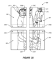
- FIG. 3C illustrates the image of FIG. 3A after being divided into four image blocks to be scanned during a second scanning level
- FIG. 3D illustrates the image of FIG. 3A after being divided into four image blocks having overlapping portions to be scanned during the second scanning level
- FIG. 4 illustrates a schematic diagram of one example of a boost based classifier, in accordance with the present invention
- FIG. 5 illustrates four basic feature units applied on a skin-color map of an image
- FIG. 6 illustrates four basic feature units applied on an edge map of the image of FIG. 5 ;
- FIG. 7 illustrates a geometrical prototype template of a 3 ⁇ 3 rectangular feature
- FIG. 8 illustrates a flow diagram describing one example of a method of scanning a digital image for detecting the representation of an object.
- an example embodiment of a method and apparatus for object detection, such as a human face, in a digital image uses a two-level scanning scheme.
- the digital image is downsampled to a smaller storage requirement size, and the downsampled image is then scanned to detect the presence of predefined objects, such as facial images, within the downsampled image.
- the original digital image is divided into multiple image blocks, each containing a portion of the original digital image. Then, each of the image blocks are scanned to detect the presence of the predefined objects within the image blocks. Because the entire original image is never scanned in a single scan, the memory size that is required to scan the image is significantly reduced.
- FIG. 1 shows one example of a computer system 100 for image detection.
- the computer system 100 can be implemented as a personal computer, or similar type of programmable workstation, that can programmably execute image detection software to enable it to process images and detect faces (or other image objects) therein.
- the computer system 100 comprises a processing unit 112 , random access memory (“RAM”) 102 , non-volatile memory 104 , a communications interface 106 , an input interface 108 and an output interface 114 , all in communication over a local bus 110 .
- the processing unit 112 loads and executes software, stored in non-volatile memory 104 , for image detection.
- the processing unit 112 registers any ongoing calculations during image detection in RAM 102 .
- the computer system 100 may be coupled to a network or server for storing images and results centrally via the communications interface 106 .
- the input interface 108 may include a keypad and a mouse for interacting with the software for image detection, such as for modifying various settings/thresholds.
- the input interface 108 can also include a scanner (or similar image capture device) for capturing images to be analyzed for image detection.
- the output interface 114 includes an electronic display that can visually present results of the image detection, if so desired, and can, for example, display settings of the software to allow for their adjustment.
- FIG. 2 a more detailed example is illustrated using a diagrammed reference to an example embodiment of an image detection system, denoted generally at 200 .
- the example image detection system 200 is configured to detect the representation of faces within an image.
- this particular application is for purposes of illustration only, and that the image detection system might also be implemented to detect other, non-facial objects within an image as well.
- the illustrated detection system 200 includes a downsampling module 218 , an image dividing module 220 , a scale size selection module 216 , a sub-window input 202 , an image scanning module 201 , and a face detection output 212 .
- the image can be broken down into one or more sub-windows. Each sub-window may be received by the image scanning module 201 from the sub-window input 202 .
- the illustrated image scanning module 201 utilizes a number of classifiers for eliminating sub-windows that have a low likelihood of representing a face.
- the illustrated image scanning module 201 utilizes a skin-color based classifier 204 , an edge based classifier 206 , and a boost based classifier 208 for detecting the representation of faces within an image.
- the skin color based classifier 204 , the edge based classifier 206 , and the boost based classifier 208 eliminate sub-windows that have a low likelihood of representing a face.
- the eliminated sub-windows are represented by the rejected sub-windows bin 214 .
- the output of the classifiers 204 , 206 and 208 is processed by the post processor 210 .
- the post processor 210 generates an output for identifying the representation of faces that exist within the digital image being scanned, and may eliminate additional sub-windows that are deemed to be non-face sub-windows.
- the post-processing component may perform a variety of operations, such as merging of multiple detects for eliminating sub-windows with a low confidence, mirroring the face detector for fast verification, removal of overlapped positive candidates, removal of minimal and maximal positive candidates having a high chances of being false positives, and removal of unusual neighboring positive candidates.
- the example face detection system 200 can be implemented to perform multiple levels of scanning on a digital image in order to detect the representation of faces within the image in a more computationally efficient manner.
- An example digital image, denoted generally at 300 is provided by way of illustration in FIG. 3A .
- the downsampling module 218 downsamples the original digital image 300 in an x-dimension 302 and in a y-dimension 304 .
- An example downsampled image, denoted generally at 320 is provided by way of illustration in FIG. 3B .
- the downsampling module 218 may downsample the original image and 300 by any factor in the x-dimension 302 and in the y-dimension 304 , the illustrated downsampled image 320 has been downsampled by a factor of two in the x-dimension and by a factor of two in the y-dimension. Therefore, the resultant downsampled image 320 requires only approximately one-fourth the storage space in comparison with the original image 300 .
- the image scanning module 201 scans the downsampled image to detect the representation of faces 322 and 326 within the downsampled image.
- the illustrated embodiment scans the downsampled image using a series of classifiers 204 , 206 and 208 , and the post-processor 210 . Any detected faces are sent to the face detection output 212 .
- the image dividing module 220 divides the original digital image into at least two image blocks, each image block containing a portion of the original digital image.
- An example digital image 340 divided into four digital image blocks 342 , 344 , 346 and 348 , is provided by way of illustration in FIG. 3C .
- each of the image blocks 342 , 344 , 346 and 348 contains a portion of the original image 300 .
- Each of the image blocks 342 , 344 , 346 and 348 is scanned individually by using, for example, the image scanning module 201 during a second scan in order to detect the representation of one or more faces 350 and 354 in the four image blocks.
- the post processor 210 Upon detecting the faces 350 and 354 , the post processor 210 sends the detected faces to the face detection output 212 .
- the image scanning module 201 is only scanning images that require, at most, approximately one-fourth of the storage space as compared to the original image 300 . Consequently, the amount of memory required by the example system 200 to perform face detection is significantly reduced.
- the image scanning module 201 is likely to find larger faces and faces that overlap the intersecting regions of the four image blocks 342 , 344 , 346 and 348 . Then, by scanning each of the image blocks 342 , 344 , 346 and 348 , smaller faces, such as the face 354 can be found.
- the image dividing module 220 simply divides the original image 300 into four or more equally sized image box 342 , 344 , 346 and 348 , without any overlapping regions between the image blocks.
- This illustrated embodiment provides the advantage of maximum memory preservation because the size of each of the box 342 , 344 , 346 and 348 is kept to a minimum.
- the image dividing module 220 divides the original digital image 300 such that four resultant image blocks 362 , 364 , 366 and 368 contain overlapping portions 378 A- 378 H of at least one of the other image blocks.
- the overlapping regions 378 A- 378 H may require slightly more memory, the overlapping regions assist in the detection of faces appearing in the intersecting regions between the four image blocks 342 , 344 , 346 and 348 of FIG. 3C .
- the face 350 in FIG. 3C is currently divided between the image block of 342 and the image block 344 . Therefore, it may be difficult for the image scanning module 201 to detect the face 350 .
- the image block 362 contains the entire face 370 , thereby increasing the detection rate of the face 370 by the image scanning module 201 .
- the starting scanning points during the scanning of the image blocks 362 , 364 , 366 and 368 may be determined such that the overlapping regions 378 A- 378 H between neighboring blocks do not need to be scanned multiple times, so as to further preserve processing and memory requirements.
- a face's “size” is measured in relation to the original image 300 , as opposed to the downsampled image 320 where the image is one fourth its original size.
- the image scanning module 201 may be configured to scan for larger-sized faces, in relation to the original image 320 , during the first scan of the downsampled image 302 , and search for smaller sized faces during the second scanning level of the divided images 340 or 360 .
- the image scanning module 201 may have a limitation on the minimum face size that it is capable of detecting.
- the image scanning module 201 may be configured to search for faces that have the size, in relation to the racial image 300 , that is twice the size in both dimensions 302 and 304 as the minimum face size that it is capable of detecting. Then, during the second scanning level of the divided image 340 or 360 , the image scanning module 201 may be configured to search for faces down to the minimum face size that it is capable of detecting.
- the image scanning module 201 may scan each image as a series of sub-windows, where the size of each sub-window is defined by a scale size, as determined by a scale size selection module.
- Each sub-window may be analyzed multiple times at different scale sizes in order to accurately detect faces of all different sizes. Therefore, the scale size selection module 216 may be tasked with fixing a minimum scale size used during the first scanning level that is larger, in relation to the original image 300 , than a minimum scale size used during the second scanning level so that the scanning of the downsampled image 320 will detect objects that are larger than the objects detected in the second scan, as described above.
- the scale size selection module 216 may select the scale sizes used during the first and second scanning levels such that the range of skills sizes used during the first scanning level overlaps with the range of skills sizes used turned the second scanning level in order to ensure that faces of all sizes will be found between the first and second scanning levels.
- the image scanning module 201 may be configured to save processing power and time during the second scanning level by skipping over regions that were previously detected as faces during the first scanning level. For example, and referring again to FIGS. 3B and 3D , assuming that the face 322 was detected within the sub-window 324 during the scanning of the downsampled image 320 , the sub-window 372 of the image block 362 , which maps to the sub-window 324 of the downsampled image 320 may be bypassed during the scan of the image block 362 . Therefore, further processing power and memory resources may be conserved, in accordance with the present embodiment.
- the scanning strategies illustrated herein only slightly affect the overall accuracy of face detection accuracy.
- the proposed scanning technique using the overlapping regions 378 A- 378 H of FIG. 3D only degrade the detect rate by approximately 1% to 2%.
- the speed at which the face detection operates is also only slightly affected, if at all.
- a small number of extra computations are needed to build the downsampled image and to process the overlapping regions 378 A- 378 H.
- these extra computations are often offset by bypassing regions during the second scanning level that have been identified as faces with high confidence during the first scanning level 1.
- the overall system performance is only affected slightly, if at all.
- the illustrated image scanning module 201 includes a skin color based classifier 204 , an edge based classifier 206 , a boost based classifier 208 , and a post processor 210 .
- the analysis of the sub-window may be terminated. If none of the classifiers 204 , 206 or 208 reject the sub-window as being a non-face image, then the sub-window is deemed to represent a face. Thus, if the sub-window fails the tests at any one stage, further processing resources and time are not wasted by further analyzing the sub-window.
- the skin color based classifier 204 analyzes the sub-windows and eliminates the sub-windows having a low likelihood of representing a face image based on the colors of the sub-windows. For example, in one embodiment, the skin color based classifier 204 generates a skin-color component, ‘F s ’. If F s falls below a predetermined level, then the sub-window is classified as a non-face and is rejected.
- F s skin-color component
- the skin based classifier 204 calculates F s (S)>0 if S is identified by Fs as a face, and F s (S) ⁇ 0 otherwise, in which case the sub-window is rejected.
- the edge based classifier 206 may analyze the sub-windows and eliminate additional sub-windows that have a low likelihood of representing a face based on an edge magnitude of the digital image within the sub-windows. For example, in one embodiment, the edge based classifier 206 generates an edge component ‘F e ’. If F e falls below a predetermined level, then the sub-window is classified as a non-face and is rejected. In one embodiment, given a sub-window, S(x, y, s, s
- the boost classifier 208 analyzes the sub-windows and eliminates additional sub-windows that have a low likelihood of representing a face image.
- the boost classifier 208 may employ an AdaBoost-like technique.
- the boost classifier denoted generally at 208 , may include a plurality of cascaded modules 402 a - 402 n . Each sub-window analyzed by the boost based classifier 208 must pass through at least a portion of the cascaded modules 402 a - 402 n before it will be detected as representing a face.
- each subsequent cascaded module 402 has a lower false-detect tolerance level than the previous cascaded module.
- sub-windows that do not represent a face are more likely to be allowed (or passed through) by cascaded modules having high false-detect tolerance levels.
- a sub-window that may successfully pass through the cascaded module 402 a due to a high false-detect tolerance level may be eliminated by the subsequent cascaded module 402 b , due to its lower false-detect tolerance level.
- the skin color based classifier 204 is designed to reject many of the non-face sub-windows, and significantly reduce the burden of the subsequent classifiers 206 and 208 .
- a description of example embodiments for implementing the skin color based classifier 204 will now be provided.
- a pre-trained skin-color model may be employed by the classifier to transform the input color image, ‘I’, to a skin-color map, where each pixel can be identified to be skin or non-skin color.
- the binary Bayesian classifier may determine a probability that each pixel represents skin or non-skin based on the RGB color value of the pixel.
- a set of sub-windows such as a pre-trained skin-color model, may be used to train the system.
- each sub-window of each training digital image may be classified as representing a face or non-face, and the pixels of the sub-windows may be used to generate skin and non-skin histograms respectively.
- the histograms may include three-dimensional arrays, with each dimension corresponding to one of the R, G and B values in the RGB color space.
- the histograms are 32 ⁇ 32 ⁇ 32 in dimension. As training images are manually identified as representing or not representing a face, the appropriate face or non-face histogram is populated with the pixel values from the images. These histograms are then used to compute the Bayesian probability of pixel color values resulting from skin and non-skin subjects. That is,
- N s is the probability that a particular color value, z, results from a given skin subject, where H s (z) is the skin histogram, and N s is the skin histogram built from the training set having the same RGB values as the pixel being analyzed, and where N s is the total number of pixels contained in the skin histogram.
- H n ( z ) H n ⁇ ( z ) N n is the probability that a particular color value, z, results from a given non-skin subject, where H n (z) is the non-skin histogram built from the training set having the same RGB values as the pixel being analyzed, and where N n is the total number of pixels contained in the non-skin histogram.
- the Bayesian classifier for each pixel is determined to be
- ⁇ g ⁇ ( z ) ⁇ 1 , if ⁇ ⁇ p ⁇ ( z ⁇
- a binary skin/non-skin color map is thus generated for each sample region, with pixels deemed to represent skin being assigned a value of 1 and pixels deemed to represent non-skin being assigned a value of 0.
- the skin color based classifier 204 may divide each sub-window into at least two frames and apply the sub-window to a skin-color map.
- Various sum-based scalar features may be calculated by determining the sum of one or more combinations of the frames. A sub-window can then be rejected if one or more of the calculated sums fall below a predetermined level. For example, and in one embodiment, given the skin color map ‘g(x)’ of a sub-window x(x, y, s), seven sum-based scalar features may be extracted from the color map for color face detection.
- the skin color map g(x) may be divided into four rectangular frames for the purpose of generating the seven sum-based scalar features.
- FIG. 5 illustrates an example sub-window divided into four rectangular frames, A, B, C, and D, as applied to a skin-color map 500 .
- All the features can be efficiently calculated by using a summed-area table or integral image of the skin-color probability map at any image scale.
- These scalar features are used to classify the sub-window x(x, y, s) by comparing them to the predetermined value, or threshold set, for each of the seven scalar features. That is,
- ⁇ i is a threshold that can be determined by evaluating results of this color feature using training data.
- the seven scalar features may be calculated and compared to the respective thresholds in a cascaded manner from f 1 to f 7 . If any one of the scalar features for a sub-window fails to meet the respective threshold, the skin color based classifier 204 deems the sub-window to represent a non-face and the determination of the remainder of the seven scalar features and other classifiers is aborted.
- the operation may be aborted prior to reaching the edge-based classifier 206 .
- a description of example embodiments for implementing the edge based classifier 206 will now be provided.
- the edge-based classifier 206 analyzes the sub-window by generating an edge map of the input image, I, using the edge magnitude of the image.
- the edge magnitude is computed using the first-order derivative:
- a Soebel edge detection technique may be employed.
- the Soebel edge detection technique uses a 3 ⁇ 3 pixel kernel to determine the edge magnitude for each pixel based on the intensity value of the pixel in relation to the intensity values of the eight adjacent pixels.
- the result is an edge magnitude map that includes edge magnitude values for the digital image.
- FIG. 6 illustrates an exemplary binary edge map 600 for a sub-window of a digital image divided into four rectangular frames: A, B, C, and D.
- the binary edge map may be obtained by determining,
- e ⁇ ( I ) ⁇ 1 , if ⁇ ⁇ s ⁇ ( I ) ⁇ ⁇ e 0 , otherwise , where s(I) is the edge magnitude and ⁇ e is an adjustable threshold.
- the seven scalar features f 1 to f 7 may be extracted in a similar manner as was described above. These scalar features may then compared to a threshold set for each of the seven scalar features, such as was described by f i (x) above.
- the edge based classifier 206 deems the sub-window is deemed non-face by the edge based classifier 206 , and the determination of the remainder of the seven scalar features and the classifiers may be aborted.
- the example boost based processor 208 includes a plurality of cascaded modules 402 a - n , where a first group of modules are used during the first scan, and a second group of the cascaded modules are used during the second scan.
- a description of example embodiments for implementing the boost based processor 208 will now be provided.
- the prototype template 700 is shown spanning the horizontal range from X 0 to X 3 , and the vertical range from Y 0 to Y 3 .
- the locations and dimensions of the nine rectangular sample regions 704 are controlled by the following set of variables:
- each frame may generally be equal, as are the heights and widths of each sample region within each frame.
- a scalar feature of the sub-window may then be computed by a linearly weighted combination of the sums of values of the pixels of the nine sample regions; that is
- the function sum(W ij ) may be computed efficiently from a summed-area table, such as described in “Summed-area tables for texture mapping”, F. Crow, SIGGGRAPH, 1984, vol. 18(3), pp. 207-212, the contents of which are incorporated by reference herein.
- the function sum(W ij ) can be computed efficiently from an integral image, such as described in “Robust real-time face detection”, Paul Viola and Michael J. Jones, International Journal of Computer Vision , vol. 57, May 2004, pp. 137-154, the contents of which are incorporated by reference herein.
- various scalar features can be generalized from a two-dimensional signal.
- an AdaBoost-like technique may be employed to select the most significant features that will be used during face detection.
- the AdaBoost-like technique may determine weak classifiers, and then linearly combine the weak classifiers to form strong classifiers.
- the strong classifiers may then be cascaded to form the cascaded modules 402 a - n , as illustrated in FIG. 4 .
- a set of N labeled training examples is given as (x 1 ; y 1 ), . . . , (x N ; y N ), where y j ⁇ +1, ⁇ 1 ⁇ is the class label for the example x i ⁇ R n .
- each weak classifier h m (x) may be associated with a single scalar feature f i .
- a stronger classifier H M (x) may be calculated by a linear combination of the M weak classifiers, that is:
- ⁇ b is the threshold for controlling the tradeoff of detect rate and false positive.
- the form of h m (x) may include a discrete function, or alternatively, many AdaBoost variants may be employed that use real h m (x) have.
- a technique referred to as a “gentle AdaBoost” may be employed for minimizing the following weighted least square error
- the optimal parameters of h m together with the best feature f * can be determined by minimizing the error of the weighted least square error, E(f i ), that is:
- AdaBoost learning may be used to select the most significant features from the proposed over-complete feature set.
- a boosted strong classifier effectively eliminates a large portion of non-face sub-windows while maintaining a high detection rate for sub-windows that represent face.
- a number of the strong classifiers, H M (x) are trained and organized in a cascaded manner, as was described previously in FIG. 4 .
- a first portion of the strong classifiers i.e., cascaded modules 402
- the remaining and more accurate strong classifiers may be used during a second scan of the image. Therefore, sub-windows which fail to pass the first scan will not be further processed by the subsequent strong classifiers included during the second scan.
- the sub-window x is finally considered to represent a face when it passes both the first and the second scan. This strategy can significant speed up the detection process and reduce false positives.
- FIG. 8 illustrates one embodiment of an aspect of a method 800 that can be used for scanning a digital image for detecting the representation of an object such as a face, and for reducing the memory and processing requirements of a computer system.
- the method 800 may be practiced, for example, in a computer system that includes one or more computer-readable media having computer-executable instructions, that when executed, implement the method 800 .
- the method 800 identifies an original digital image, such as the image 300 illustrated in FIG. 3A .
- the method 800 then downsamples the original image, at program step 804 , in an x-dimension and in a y-dimension to obtain a downsampled image, such as the example downsample image 320 illustrated in FIG. 3B .
- the downsampled image 320 requires less storage space than the original digital image 300 .
- the method 800 at program step 806 , performs a first scan of the downsampled image 320 to detect the representation of an object, such as a face, within the downsampled image.
- each image block 342 , 344 , 346 and 348 contains a portion of the original digital image 300 .
- each image block 362 , 364 , 366 and 368 contains an overlapping portion of at least one of the other image blocks.
- the method 800 performs a second scan of each of the image blocks to detect the representation of the object, such as a face, within each of the image blocks.
- the memory required to detect faces within the original image 300 can be reduced, while maintaining a high face detection level and without sacrificing a great deal of speed.
- the minimum sized face scanned for by the first scan (step 806 ) is larger than the minimum sized face scanned for during the second scan.
- the method 800 is able to preserve resources by only scanning for small faces during the second scan (step 810 ).
- larger faces that occupy more than one image block can still be detected during the first scan.
- the range of scale sizes searched for during the first scan may overlap with the range of scale sizes used during the second scan.
- the second scan may bypass regions within each of the image blocks that map to regions in the downsampled image that contain faces that were detected during the first scan (step 806 ). Therefore, regions that are already known to contain a face are only scanned a single time.
- Embodiments herein may comprise a special purpose or general-purpose computer including various computer hardware implementations. Embodiments may also include computer-readable media for carrying or having computer-executable instructions or data structures stored thereon. Such computer-readable media can be any available media that can be accessed by a general purpose or special purpose computer. By way of example, and not limitation, such computer-readable media can comprise RAM, ROM, EEPROM, CD-ROM or other optical disk storage, magnetic disk storage or other magnetic storage devices, or any other medium which can be used to carry or store desired program code means in the form of computer-executable instructions or data structures and which can be accessed by a general purpose or special purpose computer.
- Computer-executable instructions comprise, for example, instructions and data which cause a general purpose computer, special purpose computer, or special purpose processing device to perform a certain function or group of functions.
Landscapes
- Engineering & Computer Science (AREA)
- Health & Medical Sciences (AREA)
- General Health & Medical Sciences (AREA)
- Oral & Maxillofacial Surgery (AREA)
- Human Computer Interaction (AREA)
- Physics & Mathematics (AREA)
- General Physics & Mathematics (AREA)
- Multimedia (AREA)
- Theoretical Computer Science (AREA)
- Image Analysis (AREA)
Abstract
Description
is the probability that a particular color value, z, results from a given skin subject, where Hs(z) is the skin histogram, and Ns is the skin histogram built from the training set having the same RGB values as the pixel being analyzed, and where Ns is the total number of pixels contained in the skin histogram. Correspondingly,
is the probability that a particular color value, z, results from a given non-skin subject, where Hn(z) is the non-skin histogram built from the training set having the same RGB values as the pixel being analyzed, and where Nn is the total number of pixels contained in the non-skin histogram.
where θg is a threshold that can be used to adjust the trade-off between correct detect rates and false positives. A binary skin/non-skin color map is thus generated for each sample region, with pixels deemed to represent skin being assigned a value of 1 and pixels deemed to represent non-skin being assigned a value of 0.
f 1=sum(A)+sum(B)+sum(C)+sum(D)
f 2=sum(A)+sum(C)
f 3=sum(B)+sum(D)
f 4=|sum(A)+sum(C)−sum(B)−sum(D)|
f 5=sum(A)+sum(B)
f 6=sum(C)+sum(D)
f 7=|sum(A)+sum(B)−sum(C)−sum(D)|
where sum(X) denotes the pixel sum of the pixel values g(x) in a sample region Z. All the features can be efficiently calculated by using a summed-area table or integral image of the skin-color probability map at any image scale. These scalar features are used to classify the sub-window x(x, y, s) by comparing them to the predetermined value, or threshold set, for each of the seven scalar features. That is,
where θi is a threshold that can be determined by evaluating results of this color feature using training data. The seven scalar features may be calculated and compared to the respective thresholds in a cascaded manner from f1 to f7. If any one of the scalar features for a sub-window fails to meet the respective threshold, the skin color based
where s(I) is the edge magnitude and θe is an adjustable threshold. Given the edge map e(x) of a sub-window x(x,y,s), the seven scalar features f1 to f7 may be extracted in a similar manner as was described above. These scalar features may then compared to a threshold set for each of the seven scalar features, such as was described by fi(x) above. If any one of the scalar features for a sub-window fails to meet the respective threshold, the edge based
where:
is the set of all the variables, and sum(Wij) denotes the sum across all pixels of the sample region Wij. The function sum(Wij) may be computed efficiently from a summed-area table, such as described in “Summed-area tables for texture mapping”, F. Crow, SIGGGRAPH, 1984, vol. 18(3), pp. 207-212, the contents of which are incorporated by reference herein. Alternatively, the function sum(Wij) can be computed efficiently from an integral image, such as described in “Robust real-time face detection”, Paul Viola and Michael J. Jones, International Journal of Computer Vision, vol. 57, May 2004, pp. 137-154, the contents of which are incorporated by reference herein. By varying the values of
where θb is the threshold for controlling the tradeoff of detect rate and false positive. The classification of x may be obtained as ŷ(x)=sign [HM(x)] and the normalized confidence score may be obtained as |HM(x)|. The form of hm(x) may include a discrete function, or alternatively, many AdaBoost variants may be employed that use real hm(x) have.
In this manner, AdaBoost learning may be used to select the most significant features from the proposed over-complete feature set.
Claims (16)
Priority Applications (1)
| Application Number | Priority Date | Filing Date | Title |
|---|---|---|---|
| US11/750,099 US7983480B2 (en) | 2007-05-17 | 2007-05-17 | Two-level scanning for memory saving in image detection systems |
Applications Claiming Priority (1)
| Application Number | Priority Date | Filing Date | Title |
|---|---|---|---|
| US11/750,099 US7983480B2 (en) | 2007-05-17 | 2007-05-17 | Two-level scanning for memory saving in image detection systems |
Publications (2)
| Publication Number | Publication Date |
|---|---|
| US20080285849A1 US20080285849A1 (en) | 2008-11-20 |
| US7983480B2 true US7983480B2 (en) | 2011-07-19 |
Family
ID=40027537
Family Applications (1)
| Application Number | Title | Priority Date | Filing Date |
|---|---|---|---|
| US11/750,099 Expired - Fee Related US7983480B2 (en) | 2007-05-17 | 2007-05-17 | Two-level scanning for memory saving in image detection systems |
Country Status (1)
| Country | Link |
|---|---|
| US (1) | US7983480B2 (en) |
Cited By (3)
| Publication number | Priority date | Publication date | Assignee | Title |
|---|---|---|---|---|
| US20100008549A1 (en) * | 2008-07-08 | 2010-01-14 | Clay Jessen | Increasing Face Detection Speed |
| US20110091108A1 (en) * | 2009-10-19 | 2011-04-21 | Canon Kabushiki Kaisha | Object recognition apparatus and object recognition method |
| US20130103718A1 (en) * | 2011-10-21 | 2013-04-25 | International Business Machines Corporation | Memory pattern searching via displaced-read memory addressing |
Families Citing this family (11)
| Publication number | Priority date | Publication date | Assignee | Title |
|---|---|---|---|---|
| CN101470802B (en) * | 2007-12-28 | 2012-05-09 | 清华大学 | Object detection device and method |
| JP4539729B2 (en) * | 2008-02-15 | 2010-09-08 | ソニー株式会社 | Image processing apparatus, camera apparatus, image processing method, and program |
| US20090278958A1 (en) * | 2008-05-08 | 2009-11-12 | Samsung Electronics Co., Ltd. | Method and an apparatus for detecting a composition adjusted |
| KR101522985B1 (en) * | 2008-10-31 | 2015-05-27 | 삼성전자주식회사 | Apparatus and Method for Image Processing |
| US8320662B2 (en) * | 2009-01-07 | 2012-11-27 | National Instruments Corporation | Distinguishing colors of illuminated objects using machine vision |
| JP5340088B2 (en) * | 2009-09-07 | 2013-11-13 | キヤノン株式会社 | Information processing method and apparatus |
| WO2011086636A1 (en) * | 2010-01-13 | 2011-07-21 | パナソニック株式会社 | Stereo image capturing device, stereo image capturing method, stereo image display device, and program |
| KR20130098675A (en) * | 2012-02-28 | 2013-09-05 | 삼성전자주식회사 | Face detection processing circuit and image pick-up device including the same |
| JP6228527B2 (en) * | 2014-09-30 | 2017-11-08 | 富士フイルム株式会社 | Image reading apparatus and method, reading area display apparatus and method, and program |
| KR102415503B1 (en) * | 2015-08-21 | 2022-07-01 | 삼성전자주식회사 | Method for training classifier and detecting object |
| US10373019B2 (en) * | 2016-01-13 | 2019-08-06 | Ford Global Technologies, Llc | Low- and high-fidelity classifiers applied to road-scene images |
Citations (13)
| Publication number | Priority date | Publication date | Assignee | Title |
|---|---|---|---|---|
| US20020081003A1 (en) | 2000-12-27 | 2002-06-27 | Sobol Robert E. | System and method for automatically enhancing graphical images |
| US20020102024A1 (en) | 2000-11-29 | 2002-08-01 | Compaq Information Technologies Group, L.P. | Method and system for object detection in digital images |
| US20020150280A1 (en) * | 2000-12-04 | 2002-10-17 | Pingshan Li | Face detection under varying rotation |
| US20040017938A1 (en) * | 2002-04-08 | 2004-01-29 | James Cooper | Method and apparatus for detecting and/or tracking one or more colour regions in an image or sequence of images |
| US20050180627A1 (en) | 2004-02-13 | 2005-08-18 | Ming-Hsuan Yang | Face recognition system |
| US20060029265A1 (en) | 2004-08-04 | 2006-02-09 | Samsung Electronics Co., Ltd. | Face detection method based on skin color and pattern match |
| US20060034517A1 (en) | 2004-05-17 | 2006-02-16 | Mitsubishi Denki Kabushiki Kaisha | Method and apparatus for face description and recognition |
| US20060062451A1 (en) * | 2001-12-08 | 2006-03-23 | Microsoft Corporation | Method for boosting the performance of machine-learning classifiers |
| US7020337B2 (en) | 2002-07-22 | 2006-03-28 | Mitsubishi Electric Research Laboratories, Inc. | System and method for detecting objects in images |
| US20060120572A1 (en) * | 2001-12-08 | 2006-06-08 | Microsoft Corporation | System and method for multi-view face detection |
| US20060126938A1 (en) | 2004-12-09 | 2006-06-15 | Samsung Electronics Co., Ltd. | Apparatus, method, and medium for detecting face in image using boost algorithm |
| US7257271B2 (en) * | 2003-12-17 | 2007-08-14 | Eastman Kodak Company | Noise reduction in color digital images using pyramid decomposition |
| US7835549B2 (en) * | 2005-03-07 | 2010-11-16 | Fujifilm Corporation | Learning method of face classification apparatus, face classification method, apparatus and program |
-
2007
- 2007-05-17 US US11/750,099 patent/US7983480B2/en not_active Expired - Fee Related
Patent Citations (13)
| Publication number | Priority date | Publication date | Assignee | Title |
|---|---|---|---|---|
| US20020102024A1 (en) | 2000-11-29 | 2002-08-01 | Compaq Information Technologies Group, L.P. | Method and system for object detection in digital images |
| US20020150280A1 (en) * | 2000-12-04 | 2002-10-17 | Pingshan Li | Face detection under varying rotation |
| US20020081003A1 (en) | 2000-12-27 | 2002-06-27 | Sobol Robert E. | System and method for automatically enhancing graphical images |
| US20060062451A1 (en) * | 2001-12-08 | 2006-03-23 | Microsoft Corporation | Method for boosting the performance of machine-learning classifiers |
| US20060120572A1 (en) * | 2001-12-08 | 2006-06-08 | Microsoft Corporation | System and method for multi-view face detection |
| US20040017938A1 (en) * | 2002-04-08 | 2004-01-29 | James Cooper | Method and apparatus for detecting and/or tracking one or more colour regions in an image or sequence of images |
| US7020337B2 (en) | 2002-07-22 | 2006-03-28 | Mitsubishi Electric Research Laboratories, Inc. | System and method for detecting objects in images |
| US7257271B2 (en) * | 2003-12-17 | 2007-08-14 | Eastman Kodak Company | Noise reduction in color digital images using pyramid decomposition |
| US20050180627A1 (en) | 2004-02-13 | 2005-08-18 | Ming-Hsuan Yang | Face recognition system |
| US20060034517A1 (en) | 2004-05-17 | 2006-02-16 | Mitsubishi Denki Kabushiki Kaisha | Method and apparatus for face description and recognition |
| US20060029265A1 (en) | 2004-08-04 | 2006-02-09 | Samsung Electronics Co., Ltd. | Face detection method based on skin color and pattern match |
| US20060126938A1 (en) | 2004-12-09 | 2006-06-15 | Samsung Electronics Co., Ltd. | Apparatus, method, and medium for detecting face in image using boost algorithm |
| US7835549B2 (en) * | 2005-03-07 | 2010-11-16 | Fujifilm Corporation | Learning method of face classification apparatus, face classification method, apparatus and program |
Cited By (6)
| Publication number | Priority date | Publication date | Assignee | Title |
|---|---|---|---|---|
| US20100008549A1 (en) * | 2008-07-08 | 2010-01-14 | Clay Jessen | Increasing Face Detection Speed |
| US8433106B2 (en) * | 2008-07-08 | 2013-04-30 | Hewlett-Packard Development Company, L.P. | Increasing face detection speed |
| US20110091108A1 (en) * | 2009-10-19 | 2011-04-21 | Canon Kabushiki Kaisha | Object recognition apparatus and object recognition method |
| US8666176B2 (en) * | 2009-10-19 | 2014-03-04 | Canon Kabushiki Kaisha | Object recognition apparatus and object recognition method |
| US20130103718A1 (en) * | 2011-10-21 | 2013-04-25 | International Business Machines Corporation | Memory pattern searching via displaced-read memory addressing |
| US8645404B2 (en) * | 2011-10-21 | 2014-02-04 | International Business Machines Corporation | Memory pattern searching via displaced-read memory addressing |
Also Published As
| Publication number | Publication date |
|---|---|
| US20080285849A1 (en) | 2008-11-20 |
Similar Documents
| Publication | Publication Date | Title |
|---|---|---|
| US7983480B2 (en) | Two-level scanning for memory saving in image detection systems | |
| US7840037B2 (en) | Adaptive scanning for performance enhancement in image detection systems | |
| Wei et al. | Multi-vehicle detection algorithm through combining Harr and HOG features | |
| Vukadinovic et al. | Fully automatic facial feature point detection using Gabor feature based boosted classifiers | |
| US20080107341A1 (en) | Method And Apparatus For Detecting Faces In Digital Images | |
| US7844085B2 (en) | Pairwise feature learning with boosting for use in face detection | |
| US8401250B2 (en) | Detecting objects of interest in still images | |
| US8620078B1 (en) | Determining a class associated with an image | |
| US7773781B2 (en) | Face detection method and apparatus and security system employing the same | |
| US7440586B2 (en) | Object classification using image segmentation | |
| Nebehay | Robust object tracking based on tracking-learning-detection | |
| KR101896357B1 (en) | Method, device and program for detecting an object | |
| CN101178770B (en) | Image detection method and apparatus | |
| US20120213422A1 (en) | Face recognition in digital images | |
| US8103058B2 (en) | Detecting and tracking objects in digital images | |
| US9025882B2 (en) | Information processing apparatus and method of processing information, storage medium and program | |
| Jun et al. | Robust real-time face detection using face certainty map | |
| US7831068B2 (en) | Image processing apparatus and method for detecting an object in an image with a determining step using combination of neighborhoods of a first and second region | |
| US20230069960A1 (en) | Generalized anomaly detection | |
| CN106503700A (en) | Haar features multiprocessing framework face detection system and detection method based on FPGA | |
| Ranftl et al. | Face tracking using optical flow | |
| EP2545498B1 (en) | Resolution adjustment of an image that includes text undergoing an ocr process | |
| US7715632B2 (en) | Apparatus and method for recognizing an image | |
| Fang et al. | 1-D barcode localization in complex background | |
| Malikovich et al. | Triangle method for fast face detection on the wild |
Legal Events
| Date | Code | Title | Description |
|---|---|---|---|
| AS | Assignment |
Owner name: EPSON CANADA, LTD.,, CANADA Free format text: ASSIGNMENT OF ASSIGNORS INTEREST;ASSIGNORS:LU, JUWEI;ZHOU, HUI;THIYAGARAJAH, MOHANARAJ;REEL/FRAME:019310/0666;SIGNING DATES FROM 20070510 TO 20070514 Owner name: EPSON CANADA, LTD.,, CANADA Free format text: ASSIGNMENT OF ASSIGNORS INTEREST;ASSIGNORS:LU, JUWEI;ZHOU, HUI;THIYAGARAJAH, MOHANARAJ;SIGNING DATES FROM 20070510 TO 20070514;REEL/FRAME:019310/0666 |
|
| AS | Assignment |
Owner name: SEIKO EPSON CORPORATION, JAPAN Free format text: ASSIGNMENT OF ASSIGNORS INTEREST;ASSIGNOR:EPSON CANADA, LTD.,;REEL/FRAME:019488/0451 Effective date: 20070614 |
|
| STCF | Information on status: patent grant |
Free format text: PATENTED CASE |
|
| FEPP | Fee payment procedure |
Free format text: PAYOR NUMBER ASSIGNED (ORIGINAL EVENT CODE: ASPN); ENTITY STATUS OF PATENT OWNER: LARGE ENTITY |
|
| FPAY | Fee payment |
Year of fee payment: 4 |
|
| MAFP | Maintenance fee payment |
Free format text: PAYMENT OF MAINTENANCE FEE, 8TH YEAR, LARGE ENTITY (ORIGINAL EVENT CODE: M1552); ENTITY STATUS OF PATENT OWNER: LARGE ENTITY Year of fee payment: 8 |
|
| FEPP | Fee payment procedure |
Free format text: MAINTENANCE FEE REMINDER MAILED (ORIGINAL EVENT CODE: REM.); ENTITY STATUS OF PATENT OWNER: LARGE ENTITY |
|
| LAPS | Lapse for failure to pay maintenance fees |
Free format text: PATENT EXPIRED FOR FAILURE TO PAY MAINTENANCE FEES (ORIGINAL EVENT CODE: EXP.); ENTITY STATUS OF PATENT OWNER: LARGE ENTITY |
|
| STCH | Information on status: patent discontinuation |
Free format text: PATENT EXPIRED DUE TO NONPAYMENT OF MAINTENANCE FEES UNDER 37 CFR 1.362 |
|
| FP | Lapsed due to failure to pay maintenance fee |
Effective date: 20230719 |