US7871333B1 - Golf swing measurement and analysis system - Google Patents
Golf swing measurement and analysis system Download PDFInfo
- Publication number
- US7871333B1 US7871333B1 US12/777,334 US77733410A US7871333B1 US 7871333 B1 US7871333 B1 US 7871333B1 US 77733410 A US77733410 A US 77733410A US 7871333 B1 US7871333 B1 US 7871333B1
- Authority
- US
- United States
- Prior art keywords
- club head
- module
- golf swing
- golf
- segment
- Prior art date
- Legal status (The legal status is an assumption and is not a legal conclusion. Google has not performed a legal analysis and makes no representation as to the accuracy of the status listed.)
- Expired - Fee Related
Links
Images


Classifications
-
- A—HUMAN NECESSITIES
- A63—SPORTS; GAMES; AMUSEMENTS
- A63B—APPARATUS FOR PHYSICAL TRAINING, GYMNASTICS, SWIMMING, CLIMBING, OR FENCING; BALL GAMES; TRAINING EQUIPMENT
- A63B60/00—Details or accessories of golf clubs, bats, rackets or the like
- A63B60/46—Measurement devices associated with golf clubs, bats, rackets or the like for measuring physical parameters relating to sporting activity, e.g. baseball bats with impact indicators or bracelets for measuring the golf swing
-
- A—HUMAN NECESSITIES
- A63—SPORTS; GAMES; AMUSEMENTS
- A63B—APPARATUS FOR PHYSICAL TRAINING, GYMNASTICS, SWIMMING, CLIMBING, OR FENCING; BALL GAMES; TRAINING EQUIPMENT
- A63B57/00—Golfing accessories
-
- A—HUMAN NECESSITIES
- A63—SPORTS; GAMES; AMUSEMENTS
- A63B—APPARATUS FOR PHYSICAL TRAINING, GYMNASTICS, SWIMMING, CLIMBING, OR FENCING; BALL GAMES; TRAINING EQUIPMENT
- A63B69/00—Training appliances or apparatus for special sports
- A63B69/36—Training appliances or apparatus for special sports for golf
- A63B69/3623—Training appliances or apparatus for special sports for golf for driving
- A63B69/3632—Clubs or attachments on clubs, e.g. for measuring, aligning
-
- A—HUMAN NECESSITIES
- A63—SPORTS; GAMES; AMUSEMENTS
- A63B—APPARATUS FOR PHYSICAL TRAINING, GYMNASTICS, SWIMMING, CLIMBING, OR FENCING; BALL GAMES; TRAINING EQUIPMENT
- A63B2220/00—Measuring of physical parameters relating to sporting activity
- A63B2220/40—Acceleration
-
- A—HUMAN NECESSITIES
- A63—SPORTS; GAMES; AMUSEMENTS
- A63B—APPARATUS FOR PHYSICAL TRAINING, GYMNASTICS, SWIMMING, CLIMBING, OR FENCING; BALL GAMES; TRAINING EQUIPMENT
- A63B71/00—Games or sports accessories not covered in groups A63B1/00 - A63B69/00
- A63B71/06—Indicating or scoring devices for games or players, or for other sports activities
- A63B71/0619—Displays, user interfaces and indicating devices, specially adapted for sport equipment, e.g. display mounted on treadmills
Definitions
- the present invention relates to a method for determining the effectiveness of a golfer's swing requiring no golf club contact with the golf ball.
- the measurement and analysis system comprises an attachable and detachable module, that when attached to a golf club head measures three dimensional acceleration data, that is further transmitted to a computer or other smart device or computational engine where a software algorithm interprets measured data within the constraints of a multi-lever variable radius swing model using both rigid and non-rigid levers, and further processes the data to define accurate golf swing metrics.
- a computational algorithm detects the misalignment and further calibrates and corrects the data.
- U.S. Pat. No. 3,945,646 to Hammond integrates three-dimensional orthogonal axes accelerometers in the club head, and describes a means for wirelessly transmitting and receiving the resulting sensor signals.
- he does not contemplate the computational algorithms involving the multi-lever mechanics of a golf club swing required to solve for all the angles of motion of the club head during the swing with a varying swing radius.
- His premise of being able to obtain face angle only with data from his sensors 13 , and 12 (x and y directions respectively described below) is erroneous, as for one example, the toe down angle feeds a large component of the radial centrifugal acceleration onto sensor 12 which he does not account for.
- He simply does not contemplate the effects of the dynamically changing orientation relationship between the inertial acceleration forces and the associated coordinate system acting on the club head constrained by the multi-lever golf swing mechanics and the fixed measurement coordinate system of the three orthogonal club head sensors.
- the prior art disclosures all fail to offer a golf free swing analysis system that measures only acceleration forces on three orthogonal axes at the club head and interprets that limited data within the constraints of a multi-lever golf swing model using rigid and non rigid levers describing the mechanics of a swing, to determine the dynamically changing orientation relationship of inertial forces experienced at the club head and the orthogonal measurement axes fixed to the club head, resulting in the ability to accurately calculate numerous golf swing metrics.
- the present invention is a golf swing measurement and analysis system that measures directly and stores time varying acceleration forces during the entire golf club swing.
- the measurement and analysis system comprises three major components; a golf club, a club head module that is attachable to and removable from the club head, and a computer program.
- the golf club comprises a shaft and a club head with the club head comprising a face and a top surface where the module is attached.
- the module comprise a means to measure acceleration separately on three orthogonal axes, and a means to transmit the measured data to a computer or other smart device where the computer program resides.
- the computer program comprises computational algorithms for calibration of data and calculation of golf metrics and support code for user interface commands and inputs and visual display of the metrics.
- the module is attached on the head of the golf club, and during the entire golf swing it captures data from the three acceleration sensors axes.
- the acquired swing measurement data is either stored in the module for later analysis or transmitted immediately from the module to a receiver with connectivity to a computation engine.
- a computational algorithm that utilizes the computational engine is based on a custom multi-lever golf swing model utilizing both rigid and non-rigid levers. This algorithm interprets the measured sensor data to determine the dynamically changing relationship between an inertial coordinates system defined by the multi-lever model for calculation of inertial acceleration forces and the module measurement axes coordinate system attached to the club head.
- the module acceleration measurement process comprises sensors that are connected to electrical analog and digital circuitry and an energy storage unit such as a battery to supply power to the circuits.
- the circuitry conditions the signals from the sensors, samples the signals from all sensors simultaneously, converts them to a digital format, attaches a time stamp to each group of simultaneous sensor measurements, and then stores the data in memory.
- the process of sampling sensors simultaneously is sequentially repeated at a fast rate so that all acceleration forces profile points from each sensor are relatively smooth with respect to time.
- the minimum sampling rate is the “Nyquist rate” of the highest significant and pertinent frequency domain component of any of the sensors' time domain signal.
- the sensor module also contains circuitry for storing measured digital data and a method for communicating the measured data out of the module to a computational engine integrated with interface peripherals that include a visual display and or audio capabilities.
- the club head module also contains RF circuitry for instant wireless transmission of sensor data immediately after sampling to a RF receiver plugged into a USB or any other communications port of a laptop computer.
- the receiver comprises analog and digital circuitry for receiving RF signals carrying sensor data, demodulating those signals, storing the sensor data in a queue, formatting data into standard USB or other communication formats for transfer of the data to the computation algorithm operating on the computation engine.
- An alternate embedment of this invention contemplates a similar module without the RF communication circuitry and the addition of significantly more memory and USB connectivity.
- This alternate embodiment can store many swings of data and then at a later time, the module can be plugged directly into to a USB laptop port for analysis of each swing.
- Another alternate embodiment of this invention contemplates a similar club head module without the RF circuitry and with a wired connection to a second module mounted on the shaft of the club near the grip comprising a computational engine to run computational algorithm and a display for conveying golf metrics.
- FIG. 1 is a perspective view of the present invention embodied with an attached module that contains three acceleration sensors located on a three-dimensional orthogonal coordinate system with axes x f , y f , and z f , where the axes are fixed with respect to the module.
- FIG. 2 is a perspective view of the club head module attached to the club head and the alignment of the club head module three orthogonal measurement axes x f , y f , and z f , to the golf club structure.
- FIG. 3 is a perspective view of the “inertial” motion axes of the club head motion x cm , y cm and z cm as the golfer swings the club and how these axes relate to the multi-lever model components of the golfer's swing.
- FIG. 4 shows the multi-lever variable radius model system and two key interdependent angles ⁇ and ⁇ and their relationship between the two coordinate systems; the measured axes of club head module x f , y f and z f , and a second coordinate system comprising the inertial motion axes of club head travel x cm , y cm and z cm .
- FIG. 5 shows the club face angle ⁇ for different club orientations referenced to the club head travel path.
- FIG. 6 shows the toe down angle, ⁇ and it's reference to the shaft bow state and measurement axis dynamics.
- FIGS. 7 and 7A shows wrist cock angle ⁇ wc , and the shaft flex lag/lead angle ⁇ sf which together sum to the angle ⁇ .
- FIG. 8 shows the force balance for the multi-lever variable radius swing model system and the inter-relationship to both axes systems.
- FIG. 9 shows the force balance for the flexible lever portion of the multi-lever model for the toe down angle ⁇ .
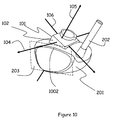
- FIG. 10 shows the mounting and alignment process of the club head module being attached to the club head and the available visual alignment structure.
- FIG. 11 shows the possible club head module mounting angle error ⁇ that is detected and then calibrated out of the raw data.
- FIG. 12 shows another club head module mounting angle error that is detected and then calibrated out of the raw data.
- FIG. 13 shows the wireless link between the club head module and the USB receiving unit plugged into a user interface device being a laptop computer.
- FIG. 14 shows a wired connection between the club head module and a custom user interface unit attached to the club shaft.
- the present invention comprises accelerometers attached to the club head that allow the motion of the club head during the swing to be determined.
- sensors are incorporated in a club head attachable module 101 .
- the module 101 has a front surface 102 and a top surface 103 and an inwardly domed attachment surface 107 .
- the sensors in module 101 measure acceleration in three orthogonal axes which include: the x f -axis 104 that is perpendicular to the front surface 102 , the z f - axis 105 that is perpendicular to x f -axis 104 and perpendicular to the top surface 103 and the y f -axis 106 that is perpendicular to both the x f -axis 104 and the z f -axis 105 .
- FIG. 2 shows the preferred embodiment of the invention, which is the module 101 with three orthogonal measurement axes 104 , 105 and 106 that is attached to the top surface 204 of the club head 201 .
- the club head module 101 attachment surface 107 is attached to club head 201 top surface 204 with a conventional double sided tape with adhesive on top and bottom surfaces (not shown).
- the z f -axis 105 is aligned so that it is parallel to the club shaft 202 .
- the x f -axis 104 is aligned so that is orthogonal to the z f -axis 105 and perpendicular to the plane 203 that would exist if the club face has a zero loft angle.
- the y f -axis 106 is aligned orthogonally to both the x f -axis 104 and z f -axis 105 .
- the plane created by the x f -axis 104 and the y f -axis 106 is perpendicular to the non-flexed shaft 202 .
- the plane created by the y f -axis 106 and the z f -axis 105 is parallel to the plane 203 that would exist if the club face has a zero loft angle.
- the mathematical label a sx represents the acceleration force measured by a sensor along the club head module 101 x f -axis 104 .
- the mathematical label a sy represents the acceleration force measured by a sensor along the club head module 101 y f -axis 106 .
- the mathematical label a sz represents the acceleration force measured by a sensor along the club head module 101 z f -axis 105 .
- club head module of the preferred embodiment is not aligned exactly with the references of the golf club there is an algorithm that is used to detect and calculated the angle offset from the intended references of the club system and a method to calibrate and correct the measured data. This algorithm is covered in detail after the analysis is shown for proper club head module attachment with no mounting angle variations.
- Club head motion is much more complicated than just pure linear accelerations during the swing. It experiences angular rotations of the fixed sensor orthogonal measurement axes, x f -axis 104 , y f -axis 106 and z f -axis 105 of module 101 around all the center of mass inertial acceleration force axes during the swing, as shown in FIG. 3 .
- the three orthogonal measurement axes x f -axis 104 , y f -axis 106 and z f -axis 105 of module 101 , along with a physics-based model of the multi-lever action of the swing of the golfer 301 , are sufficient to determine the motion relative to the club head three-dimensional center of mass axes with the x cm -axis 303 , y cm -axis 305 and z cm -axis 304 .
- the mathematical label a z is defined as the acceleration along the z cm -axis 304 , the radial direction of the swing, and is the axis of the centrifugal force acting on the club head 201 during the swing from the shoulder 306 of the golfer 301 . It is defined as positive in the direction away from the golfer 301 .
- the mathematical label a x is the defined club head acceleration along the x cm -axis 303 that is perpendicular to the a z -axis and points in the direction of instantaneous club head inertia on the swing arc travel path 307 .
- the club head acceleration is defined as positive when the club head is accelerating in the direction of club head motion and negative when the club head is decelerating in the direction of club head motion.
- the mathematical label a y is defined as the club head acceleration along the y cm -axis 305 and is perpendicular to the swing plane 308 .
- the dynamically changing relationship between the two coordinate systems defined by the module 101 measurements coordinate system axes x f -axis 104 , y f -axis 106 and z f -axis 105 and the inertial motion acceleration force coordinate system axes x cm -axis 303 , y cm -axis 305 and z cm -axis 304 , must be defined. This is done through the constraints of the multi-lever model partially consisting of the arm lever 309 and the club shaft lever 310 .
- the multi lever system as shown in FIG. 4 shows two interdependent angles defined as angle ⁇ 401 which is the angle between the club head module 101 z f -axis 105 and the inertial z cm -axis 304 and the angle ⁇ 403 which is the sum of wrist cock angle and shaft flex lag/lead angle (shown later in FIGS. 7 and 7A ).
- the angle ⁇ 401 is also the club head rotation around the y cm -axis 106 (not shown in FIG. 4 but is perpendicular to the page at the club head center of mass) and is caused largely by the angle of wrist cock, and to a lesser extent club shaft flexing during the swing.
- the length of the variable swing radius R 402 is a function of the fixed length arm lever 309 , the fixed length club shaft lever 310 and the angle ⁇ 401 .
- the angle ⁇ 401 can vary greatly, starting at about 40 degrees or larger at the start of the downswing and approaches zero at club head maximum velocity.
- the inertial x cm -axis 303 is as previously stated perpendicular to the inertial z cm -axis 304 and variable radius R 402 .
- FIG. 5 shows the angle ⁇ 501 which is the club face angle and is defined as the angle between the plane 502 that is perpendicular to the club head travel path 307 and the plane that is defined for zero club face loft 203 .
- the angle ⁇ 501 also represents the club head rotation around the z f -axis 105 .
- the angle ⁇ 501 varies greatly throughout the swing starting at about 90 degrees or larger at the beginning of the downswing and becomes less positive and perhaps even negative by the end of the down stroke. When the angle ⁇ 501 is positive the club face angle is said to be “OPEN” as shown in club head orientation 503 .
- the angle ⁇ 501 will be zero or said to be “SQUARE” at the point of maximum club head velocity as shown in club head orientation 504 . If the angle ⁇ 501 is negative the club face angle is said to be “CLOSED” as shown in club head orientation 505 .
- FIG. 6 shows angle ⁇ 601 which is referred to as the toe down angle and is defined as the angle between the top of a club head 201 of a golf club with a non bowed shaft state 602 and a golf club head 201 of a golf club with bowed shaft state 603 due to the centrifugal force pulling the club head toe downward during the swing.
- the angle ⁇ is a characteristic of the multi-lever model representing the non rigid club lever.
- the angle ⁇ 601 also represents the club head 201 rotation around the x f -axis 104 (not shown in FIG. 6 , but which is perpendicular to the y f -axis 106 and z f -axis 105 intersection).
- the angle ⁇ 601 starts off at zero at the beginning of the swing, and approaches a maximum value of a few degrees at the maximum club head velocity.
- FIGS. 7 and 7A show the angle ⁇ 403 which is the sum of angles ⁇ wc 701 , defined as the wrist cock angle, and ⁇ sf 702 , defined as the shaft flex lag/lead angle.
- the angle ⁇ sf 702 is the angle between a non-flexed shaft 703 and the flexed shaft state 704 , both in the swing plane 308 defined in FIG. 3 , and is one characteristic of the non rigid lever in the multi-lever model.
- the shaft leg/lead flex angle ⁇ sf 702 is caused by a combination of the inertial forces acting on the club and the wrist torque provided by the golfer's 301 wrists 705 and hands 706 on the shaft grip 707 .
- FIG. 8 shows the force balance for the multi-lever swing system.
- the term a v 805 is the vector sum of a x 804 and a z 803 .
- the term F v 806 is also, from the force balance, the vector sum of the tensile force, F t 807 , in the shaft due to the shoulder torque 801 , and F wt 808 , due to wrist torque 802 .
- the angle between force vector F v 806 and the swing radius, R 402 is the sum of the angles ⁇ 401 and ⁇ wt 809 .
- the rotation angles describing the orientation relationship between the module measured axis coordinate system and the inertial acceleration force axes coordinate system can be determined from the sensors in the club head module 101 through the following relationships: 1.
- a sx a x cos( ⁇ )cos( ⁇ ) ⁇ a y sin( ⁇ ) ⁇ a z cos( ⁇ )sin( ⁇ ) 2.
- a sy a x sin( ⁇ )cos( ⁇ )+ a y cos( ⁇ )+ a z (sin ⁇ ) ⁇ sin( ⁇ )sin( ⁇ )), 3.
- a sz a x sin( ⁇ ) ⁇ a y sin( ⁇ )cos( ⁇ )+ a z cos( ⁇ )
- the angle ⁇ 501 also known as the club face approach angle, varies at least by 180 degrees throughout the backswing, downswing, and follow through. Ideally it is zero at maximum velocity, but a positive value will result in an “open” clubface and negative values will result in a “closed” face.
- the angle ⁇ 501 is at the control of the golfer and the resulting swing mechanics, and is not dependent on either a x or a z . However, it can not be known a-priori, as it depends entirely on the initial angle of rotation around the shaft when the golfer grips the shaft handle and the angular rotational velocity of angle ⁇ 501 during the golfer's swing.
- angle ⁇ 601 is dependent on a z , where the radial acceleration causes a centrifugal force acting on the center of mass of the club head, rotating the club head down around the x f -axis into a “toe” down position of several degrees. Therefore, angle ⁇ 601 is a function of a z . This function can be derived from a physics analysis to eliminate another unknown from the equations.
- the angle ⁇ 401 results from both club shaft angle 702 lag/lead during the downswing and wrist cock angle 701 .
- Wrist cock angle is due both to the mechanics and geometry relationships of the multi lever swing model as shown in FIG. 4 and the amount of torque exerted by the wrists and hands on the shaft.
- the effect of the angle ⁇ 401 in the multi lever variable radius swing model is to introduce a z components into a sx and a sy , and an a x component into a sz .
- the angle ⁇ 401 can vary from a large value at the start and midpoint of the down stroke when a z is growing from zero. In later portion of the down stroke a z becomes very large as angle ⁇ 401 tends towards zero at maximum velocity.
- the angle ⁇ 401 introduces an a x component into a sz . This component will be negligible at the point of maximum club head velocity where angle ⁇ 401 approaches zero, but will be significant in the earlier part of the swing where angle ⁇ 401 is large and the value of a x is larger than that for a z .
- the cos( ⁇ ) term in equations (4) and (5) is the projection of a x onto the x f -y f plane, which is then projected onto the x f axis 104 and the y f axis 106 . These projections result in the a x cos( ⁇ )cos( ⁇ ) and a x sin( ⁇ )cos( ⁇ ) terms respectively in equations (4) and (5).
- the projection of a x onto the z f -axis 105 is given by the a x sin( ⁇ ) term in equation (6).
- the sin( ⁇ ) terms in equations (4) and (5) are the projection of a z onto the plane defined by x f axis 104 and the y f axis 106 , which is then projected onto the x f axis 104 and y f axis 106 through the a z cos( ⁇ )sin( ⁇ ) and a z sin( ⁇ )sin( ⁇ ) terms respectively in equations (4) and (5).
- the projection of a z onto the z f -axis 105 is given by the a z cos( ⁇ ) term in equation (6).
- the angle ⁇ 601 introduces yet another component of a z into a sy .
- the angle ⁇ 601 reaches a maximum value of only a few degrees at the point of maximum club head velocity, so its main contribution will be at this point in the swing. Since angle ⁇ 601 is around the x f -axis 104 , it makes no contribution to a sx , so its main effect is the a z sin( ⁇ ) projection onto the y f -axis 106 of equation (5). Equations (4) and (5) can be simplified by re-writing as: 11.
- Equation 15 From equation (15) it is seen that the simple relationship between a sx and a sy of equation (10) is modified by the addition of the a z term above. Equations (4) and (6) are re-written as:
- ⁇ ⁇ sin ⁇ ( ⁇ ) a x ⁇ a sz + a sx 2 cos 2 ⁇ ( ⁇ ) ⁇ 1 - cos 2 ⁇ ( ⁇ ) ⁇ ( a sz 2 - a x 2 a sx 2 ) a sz 2 + a sx 2 cos 2 ⁇ ( ⁇ ) .
- angle ⁇ 401 can be found from an analysis of the angle ⁇ 403 , which is the sum of the angles ⁇ wc 701 , due to wrist cock and ⁇ sf 702 due to shaft flex lag or lead.
- Angle ⁇ 403 , and angle ⁇ 401 are shown in FIG. 4 in relationship to variable swing radius R 402 , fixed length arm lever A 309 , and fixed length club shaft lever C 310 .
- the mathematical equations relating these geometric components are: 21.
- R 2 A 2 +C 2 +2 AC cos( ⁇ ) 22.
- a 2 R 2 +C 2 ⁇ 2 RC cos( ⁇ )
- Using R 2 from equation (21) in (22) yields a simple relationship between ⁇ and ⁇ : 23.
- a cos ⁇ 1 ((R cos( ⁇ ) ⁇ C ) ⁇ C )/ A )
- the swing radius, R 402 can be expressed either in terms of cos( ⁇ ) or cos( ⁇ ). Equation (21) provides R directly to be: 24.
- Equation (22) is a quadratic for R which is solved to be: 25.
- R C cos( ⁇ )+ ⁇ square root over (C 2 (cos( ⁇ ) ⁇ 1)+ A 2 ) ⁇ .
- ⁇ ⁇ a z a z - radial - d V R d t
- the acceleration a v 805 is the vector sum of a x 804 and a z 803 with magnitude:
- a torque 901 acting on club head 201 with mass M is generated by the acceleration vector 902 on the z cm -axis 304 with magnitude a z acting through the club head 201 center of mass 903 .
- the center of mass 903 is a distance 904 from the center axis 905 of club shaft 202 with length C 310 and stiffness constant K.
- the mathematical label for distance 904 is d. Solving the force balance with the constraints of a flexible shaft K gives an expression for ⁇ 601 :
- Equations (42) for ⁇ 601 , (46) for ⁇ 501, and (20) for ⁇ 401 need to be solved either numerically or iteratively using equations (32) for a x , (33) for a z , and (25) for R 402 .
- This task is extremely complex.
- some innovative approximations can yield excellent results with much reduced complexity.
- One such approach is to look at the end of the power-stroke segment of the swing where V R and its time derivative go to zero, for which from equations (32), (33), (35) and (40):
- Equation (47) can not be blindly applied without first considering the implications for the function f( ⁇ ) defined by equations (13) and (14), which has a functional dependence on cos( ⁇ ) through the a sx term, which will not be present when (47) is used in (13).
- Equation (49) is applicable only when equation (47) is used for the angle ⁇ 401 .
- a preferred embodiment is next described that uses the simplifying equations of (47) through (49) to extract results for ⁇ 501 and ⁇ 401 using (42) as a model for ⁇ 601 . It also demonstrates how the wrist cock angle ⁇ wc , 701 and shaft flex angle ⁇ sf 702 can be extracted, as well as the mounting angle errors of the accelerometer module. Although this is the preferred approach, other approaches fall under the scope of this invention.
- V V ⁇ is the club head velocity and dt is the time increment between sensor data points.
- the instantaneous velocity of the club head traveling on an arc with radius R is from equation (29):
- ⁇ ⁇ a ch 1 2 ⁇ ( 1 R ⁇ d R d t + 1 a sz ⁇ d a sz d t - tan ⁇ ( ⁇ ) ⁇ d ⁇ d t ) ⁇ Ra sz ⁇ cos ⁇ ( ⁇ )
- equation (52) and (60) back into equations (50) and (51) we have the equations containing all golf swing metric angles assuming no module mounting angle errors in terms of direct measured sensor outputs: 61.
- a sx a chsz ( ⁇ square root over (R cos( ⁇ )) ⁇ / ⁇ square root over (R Max ) ⁇ )cos( ⁇ )cos( ⁇ ) ⁇ a sz cos( ⁇ )cos( ⁇ )sin( ⁇ ) 62.
- a sy a chsz ( ⁇ square root over (R cos( ⁇ )) ⁇ / ⁇ square root over (R Max ) ⁇ )tan( ⁇ )cos( ⁇ )+ a sz cos( ⁇ )sin( ⁇ ) ⁇ a sz cos( ⁇ )tan( ⁇ )sin( ⁇ ) Using equation (62) to solve for ⁇ , since this is the only equation that contains both ⁇ and ⁇ , yields:
- ⁇ ⁇ tan ⁇ ( ⁇ ) a sy - a sz ⁇ cos ⁇ ( ⁇ ) ⁇ sin ⁇ ( ⁇ ) a chsz ⁇ ( R ⁇ ⁇ cos ⁇ ( ⁇ ) / R Max ) ⁇ cos ⁇ ( ⁇ ) - a sz ⁇ cos ⁇ ( ⁇ ) ⁇ sin ⁇ ( ⁇ )
- the angle ⁇ 601 is a function of a sz through equations (42), (48) and (52).
- the curve fit constant, C ⁇ is required since different shafts can have an overall stiffness constant that is equal, however, the segmented stiffness profile of the shaft can vary along the taper of the shaft.
- the value of C ⁇ will be very close to one, typically less than 1/10 of a percent variation for the condition of no module mounting angle error from the intended alignment. Values of C ⁇ greater or less than 1/10 of a percent indicates a module mounting error angle along the y cm -axis which will be discussed later.
- ⁇ ⁇ ⁇ C ⁇ ⁇ tan - 1 ⁇ ( a ch a z - radial )
- the curve fit parameter, C ⁇ has an initial value of 0.75.
- the mounting of the club head module 101 is prone to variation in alignment of the x f -axis 104 , z f -axis 105 , and y f -axis 106 with respect to the golf club reference structures described in FIG. 2 .
- the front surface 102 of the club head module 101 can easily be aligned with the club face/club head top surface seam 1002 .
- This alignment results in the y f -axis 106 being parallel to the plane 203 which is the plane created if the club face has zero loft.
- the module 101 mount angle errors can be described with two angles resulting from the following conditions:
- the issue of mounting angle variation is most prevalent with the club head module 101 being rotated around the y f -axis.
- the club head module 101 is mounted with the x f -axis 104 parallel to the plane 1101 that is defined as perpendicular to the shaft axis 1102 .
- the club head module 101 is mounted closer to the club face seam 1002 causing a negative value for the angle ⁇ 1103 between the plane 1101 and the x f -axis 104 .
- FIG. 11 the club head module 101 is mounted closer to the club face seam 1002 causing a negative value for the angle ⁇ 1103 between the plane 1101 and the x f -axis 104 .
- the club head module 101 is mounted further from the seam 1002 resulting in a positive value for the angle ⁇ 1103 between the plane 1101 and the x f -axis 104 .
- the mounting error angle ⁇ 1103 typically varies between ⁇ 1 degrees and +6 degrees. This angle creates a small rotation around the y f -axis 106 resulting in a misalignment of the x f -axis 104 and also the z f -axis 105 .
- This mounting error can be experimentally determined using a standard golf swing.
- ⁇ sz-true ⁇ sz /cos( ⁇ )
- the travel path 307 is not linear for a golf swing which creates a radial component due to the fixed orientation error between the offset module measurement coordinate system and the properly aligned module measurement coordinate system.
- any misalignment of the club head module axis by angle ⁇ creates an a z-radial component as measured by the misaligned x f -axis 104 .
- the a z-radial component contributes to the a sx measurement in the following manner: 68.
- the angle ⁇ 1201 is zero when the club head module 101 is perfectly mounted, defined as when the club head module 101 axis y f -axis 106 is parallel with the plane 1101 , that is perpendicular to the shaft axis 1102 .
- FIG. 12A when the club head module 101 is mounted closer to the shaft the y f -axis 106 intersects the plane 1101 creating a negative value for the angle ⁇ 1201 .
- the angle ⁇ 1201 is a positive value resulting from the intersection of the y f -axis 106 and the plane 1101 when the module 101 is mounted further away from the shaft.
- mounting error angle ⁇ 1201 is achieved by evaluating C ⁇ resulting from the iterative solution steps 2 though 4 described earlier. If C ⁇ is not very close or equal to one, then there is an additional a z -radial contribution to a sy from mounting error angle ⁇ 1201 .
- ⁇ sz-cal ⁇ sz /cos ⁇
- the new calibrated data arrays a sy-cal and a sz-cal are now used and replaces all a sy and a sz values in previous equations which complete the detection and calibration of club head module mounting errors due to a mounting error rotation around the x f -axis 104 .
- the preferred embodiment described above is able to define the dynamic relationship between the module 101 measured axes coordinate system and the inertial acceleration force axes coordinate system using the multi-lever model and to define all related angle behaviors, including module 101 mounting errors.
- All of the dynamically changing golf metrics described as angle and or amplitude values change with respect to time. To visually convey these metrics to the golfer, they are graphed in the form of value versus time.
- the graphing function can be a separate computer program that retrieves output data from the computational algorithm or the graphing function can be integrated in to a single program that includes the computational algorithm.
- the standard golf swing can be broken into four basic interrelated swing segments that include the backswing, pause and reversal, down stroke, also called the power-stroke, and follow-through.
- the relationships of the data component dynamics can now be evaluated to define trigger points that can indicate start points, end points, or transition points from one swing segment to another.
- trigger points are related to specific samples with specific time relationships defined with all other points, allowing precise time durations for each swing segment to be defined.
- the logic function that is employed to define a trigger point can vary since there are many different conditional relationships that can be employed to conclude the same trigger point.
- the logic to define the trigger point that defines the transition between the back swing segment and the pause and reversal segment is:
- the time relationship between maximum club head velocity and contact with the strike target can be achieved.
- the low mass object such as a golf waffle ball
- the mass of the substitute strike object is small enough that it does not substantially change the inertial acceleration forces acting on the club head or the dynamically changing relationship of the inertial axes coordinate system in relation to the module measured axes coordinate system.
- the data transfer from the club head module 101 to a user interface can take place in two different ways: 1) wirelessly to a receiver module plugged into a laptop or other smart device, or 2) a wired path to a user module that is attached to the golf club near the golf club grip.
- the preferred embodiment as shown in FIG. 13 demonstrates the module 101 transmitting measured data through a wireless method 1303 to a receiver module 1301 that is plugged into a computer laptop 1302 .
- the receiver module 1301 transfers the data through a USB port to the computer laptop 1302 where the data is processed by the computational algorithm and displayed to the golfer 301 .
- the club head module 101 communicates swing data through a wired connection 1401 to a user interface module 1402 that is attached to the club shaft 202 below the grip 1403 .
- the interface module 1402 contains the processing power to compute the metrics and display those metrics on the graphical and text display 1404 .
- the approach developed above can also be applied for a golf club swing when the golf club head contacts the golf ball.
- the above analysis returns the values of the three angles and club head velocity just before impact. Using these values along with the sensor measurements after impact describing the change in momentum and the abrupt orientation change between the module's measured sensor coordinate system and the inertial motional acceleration force coordinate system will enable the determination of where on the club head face the ball was hit, and the golf ball velocity.
Landscapes
- Health & Medical Sciences (AREA)
- General Health & Medical Sciences (AREA)
- Physical Education & Sports Medicine (AREA)
- Golf Clubs (AREA)
Abstract
Description
-
- 1. Golf club head time varying velocity for a significant time span before and after maximum velocity of the swing.
- 2. Time varying swing radius for a significant time span before and after maximum velocity of the swing.
- 3. Golf club head face approach angle of the golf club head, whether the club face is “open”, “square”, or “closed”, and by how much measured in degrees, for a significant time span before and after maximum velocity of the swing.
- 4. Wrist cock angle during the swing, for a significant time span before and after maximum velocity of the swing.
- 5. Club shaft lag/lead flexing during the swing, for a significant time span before and after maximum velocity of the swing.
- 6. Club head toe down angle during the swing, for a significant time span before and after maximum velocity of the swing.
- 7. Club head acceleration force profile for the backswing that include time varying vector components and total time duration.
- 8. Club head acceleration force profile for the pause and reversal segment of the swing after backswing that includes time varying vector components and total time duration.
- 9. Club head acceleration force profile for the power-stroke after pause and reversal that includes time varying vector components and total time duration.
- 10. Club head acceleration force profile for the follow through after power-stroke that includes time varying vector components and total time duration.
- 11. Club head swing tempo profile which includes total time duration of tempo for the backswing, pause and reversal, and power-stroke and provides a percentage break down of each segment duration compared to total tempo segment duration.
1. a sx =a xcos(Φ)cos(η)−a ysin(Φ)−a zcos(Φ)sin(η)
2. a sy =a xsin(Φ)cos(η)+a ycos(Φ)+a z(sinΩ)−sin(Φ)sin(η)),
3. a sz =a xsin(η)−a ysin(Ω)cos(Φ)+a zcos(η)
The following is a reiteration of the mathematical labels for the above equations.
-
- ax is the club head acceleration in the xcm-axis 303 direction.
- ay is the club head acceleration in the ycm-
axis 305 direction. - az is the club head acceleration in the zcm-
axis 304 direction. - asx is the acceleration value returned by the
club head module 101 sensor along the xf-axis 104. - asy is the acceleration value returned by the
club head module 101 sensor along the yf-axis 106. - asz is the acceleration value returned by the
club head module 101 sensor along the zf-axis 105.
During a normal golf swing with aflat swing plane 308, ay will be zero, allowing the equations to be simplified:
4. a sx =a x cos(Φ)cos(η)−a z cos(Φ)sin(η)
5. a sy =a x sin(Φ)cos(η)+a z(sin(Ω)−sin(Φ)sin(η)
6. a sz =a x sin(η)+a z cos(η)
These equations are valid for a “free swing” where there is no contact with the golf ball.
7. a sx =a xcos(Φ)
8. a sy =a xsin(Φ)
9. a sz =a z
11. a sx=(a xcos(η)−a zsin(η))cos(Φ)=f(η)cos(Φ) and
12. a sy=(a xcos(η)−a zsin(η))sin(Φ)+a zsin(Ω)=f(η)sin(Φ)+a z sin(Ω) where
13. f(η)=a xcos(η)−a zsin(η). From (11):
which when inserted into (12) obtains:
15. βsy=αsx tan(Φ)+a zsin(Ω)
These equations are simply solved by substitution to yield:
21. R 2 =A 2 +C 2+2AC cos(α)
22. A 2 =R 2 +C 2−2RC cos(η)
Using R2 from equation (21) in (22) yields a simple relationship between α and η:
23. a=cos−1((R cos(η)−C)−C)/A)
The swing radius,
24. R={square root over (C2 +A 2+2ACcos(α))}.
Equation (22) is a quadratic for R which is solved to be:
25. R=C cos(η)+{square root over (C2(cos(η)−1)+A 2)}.
The acceleration az is parallel with the direction of
Now define:
so that:
30. V Γ={square root over (RaZ-radial)},
Next define:
Because (31) has the
The acceleration av 805 is the vector sum of ax 804 and az 803 with magnitude:
The resulting magnitude of the force acting on the club head is then:
36. F v =m s a v
37. β=η for no wrist torque.
38. β=η+ηwt where:
39. F wt =F vsin(ηwt).
The
where Cη<1 is a curve fitting parameter to match the data, and is nominally around the range of 0.75 to 0.85. From the fitted value:
41. ηwt=(1−C η)β
Re-arranging terms:
44. (a sy −a sz cos(η)sin(Ω))cos(Φ)=a sxsin(Φ)−a sxsin(η)sin(Ω)
Squaring both sides, and using the identity cos2(Φ)=1-sin2(Φ) yields a quadratic equation for sin(Φ):
Equation (45) has the solution:
where the terms in (46) are:
b 1 =a sx 2+(a sy −a szcos(η)sin(Ω))2
b 2=−2a sx 2sin(η)sin(Ω)
b 3 =a sx 2(sin(η)sin(Ω))2−(a sy −a szcos(η)sin(Ω))2
In this part of the swing the asx term will be much smaller than the asz term and equation (18) can be approximated by:
48. a z =a z-radial =a szcos(η).
During the earlier part of the swing, the curve fit coefficient Cη would accommodate non-zero values of VR and its time derivative as well as the force due to
49. a xy=(a xcos(η)−a zsin(η))tan(Φ)+a zsin(Ω).
50. a sx =a chcos(Φ)cos(η)−a z-radialcos(Φ)sin(η)
51. a sy =a chtan(Φ)cos(η)+a z-radialsin(Ω)−a z-radialtan(Φ)sin(η)
52. a z-radial =a szcos(η)
Using equation (52) for az-radial in (55):
During the early part of the downswing, all the derivative terms will contribute to ach, but in the later part of the downswing when R is reaching its maximum value, Rmax, and η is approaching zero, the dominant term by far is the dasz/dt term, which allows the simplification for this part of the swing:
With discreet sensor data taken at time intervals Δt, the equivalent of the above is:
It is convenient to define the behavior for ach for the case where R=Rmax and η=0, so that from equation (52) az-radial=asz, which defines:
Then the inertial spatial translation acceleration component of the club head is:
61. a sx =a chsz({square root over (R cos(η))}/{square root over (RMax)})cos(Φ)cos(η)−a szcos(η)cos(Φ)sin(η)
62. a sy =a chsz({square root over (R cos(η))}/{square root over (RMax)})tan(Φ)cos(η)+a szcos(η)sin(Ω)−a szcos(η)tan(Φ)sin(η)
Using equation (62) to solve for Φ, since this is the only equation that contains both η and Ω, yields:
-
- 1. For a golf swing approaching max velocity the value of η approaches zero,
- 2. Ω is at a maximum value when centrifugal force is highest, which occurs at maximum velocity.
- 3. The club face angle, Φ, can vary greatly at maximum club head velocity. However, regardless of the angle at maximum velocity the angle is changing at a virtual constant rate just before and after the point of maximum club head velocity.
This knowledge allows for all equations to be solved, through an interactive process using starting points for the curve fit parameters.
The constants in equation (64) are:
-
- CΩ Multiplying curve fit factor applied for iterative solution
- d Distance from housel to center of gravity (COG) of club head
- ms mass of club head system, including club head and Club Head Module
- asz The measured zf-
axis 105 acceleration force value - K Stiffness coefficient of shaft supplied by the golfer or which can Be determined in the calibration process associated with the user profile entry section of the analysis program
- C Club length
Theangle η 401 is found from equation (47):
The curve fit parameter, Cη, has an initial value of 0.75.
-
- 1. Determine from sample points of asz the zero crossing position of achsz. This is the point where the club head acceleration is zero and therefore the maximum velocity is achieved. Because the samples are digitized quantities at discrete time increments there will be two sample points, where achsz has a positive value and an adjacent sample point where achsz has a negative value.
- 2. Course tune of Ω 601: Use initial approximation values to solve for the numerator of tan (Φ) of equation (63) with respect to the sample point where ach passes through zero:
- a. Numerator of tan (Φ)={asy−asz cos(η)sin(Ω)}
- b. The numerator of tan (Φ) in equation 63 represents the measured value of asy minus az-radial components resulting from angle Ω with the following conditions at maximum velocity:
- i. Toe down angle Ω, which is at its maximum value at maximum club head velocity, where maximum asz is achieved at η=0, for which asz=az-radial From equation (52).
- ii.
Angle η 401, which is a function of wrist cock and shaft flex lag/lead, is zero when maximum velocity is reached and ach is zero. - c. Use the multiplying constant CΩ to adjust the
Ω 601 equation so that the tan (Φ) numerator function sample point value, equivalent to the first negative sample point value of ach, is set to the value zero.
- 3. Use new course tune value for the
Ω 601 function to calculate Φ 501 from equation (63) for all sample points. - 4. Next, fine tune the multiplying constant CΩ of the
Ω 601 function by evaluating the slope ofΩ 501, for the point pairs before, through, and after maximum velocity.- a. Examine sample point pairs of the total tan (Φ) function given by equation (63) before maximum velocity, through maximum velocity, and after maximum velocity, evaluating slope variation across sample pairs.
- b. Evaluate sequential slope point pairs comparing slopes to determine a variation metric.
- c. Tune multiplying constant CΩ of
Ω 601 function in very small increments until the slope ofΦ 501 of all sample point pairs are equivalent. - d. Now the value of the Ω function is defined but the value of η is still given with the initial value of Cη=0.75. Therefore, even though the value of
Φ 501 is exact for values very near max velocity where η 401 approaches zero, values ofΦ 501 are only approximations away from maximum velocity sinceΦ 501 is a function ofη 401, which at this point is limited by the initial approximation.
- 5. Calculate all sample points for the for the following functions:
- a. The fine tuned
function Ω 601 - b.
Approximate function η 401 with Cη=0.75. - c.
Function Φ 501 from equation (63) - i. Which will be exact for sample points close to maximum velocity
- ii. Which will be an approximation for the sample points away from max velocity because the
function η 401 is still an approximate function.
- a. The fine tuned
- 6. Tune the multiplying curve fit constant Cη of the
η 401 function using equation (61). This is done by rewriting equation (61) into a form which allows the comparison of asx minus the asz components which must be equal to achsz. The evaluation equation is from (61):
a. {a sx +a szcos(η)cos(φ)sin(η)}/{cos(φ)cos(η)}=a chsz({square root over (R cos(η))}/{square root over (RMax)})- b. If everything were exact, the two sides of this equation would be equal. If not, they will differ by the variance:
Variance={a sx +a szcos(η)cos(φ)sin(η)}/{cos(φ)cos(η)}−a chsz({square root over (R cos(η))}/{square root over (RMax)}) - c. This variance metric is summed across a significant number of sample points before and after maximum velocity for each small increment that Cη is adjusted.
- d. The minimum summed variance metric set defines the value of the constant Cη for the
η 401 function.
- b. If everything were exact, the two sides of this equation would be equal. If not, they will differ by the variance:
- 7. Compare the value of Cη obtained at the conclusion of the above sequence with the starting value of Cη, and if the difference is greater than 0.1 repeat steps 3 through 7 where the initial value for Cη in step 3 is the last iterated value from step 6.d. When the difference is less than 0.1, the final value of Cη has been obtained.
- 8.
Angle α 403 is now solved from equation (23) withη 401 across all sample points:
α=cos−1((R cos(η)−C)/A)- a.
α 403 represents the sum of wrist cock angle and shaft flex lag/lead angle as defined by α=αwc+αsf. - b. In a standard golf swing the wrist cock angle is a decreasing angle at a constant rate during the down stroke to maximum club head velocity. Therefore, the angle can be approximated as a straight line from the point where wrist cock unwind is initiated.
- c. The slope of the
angle α we 701 is: - i. [αwc (at wrist cock unwind initiation)-αwc (club head max Velocity)]/ΔT, where ΔT is the time duration for this occurrence.
- d. Since
α wc 701 goes to zero at the point of maximum velocity and the time duration αT is known, the function ofangle α wc 701 is now defined.
- a.
- 9. The shaft
flex angle α sf 702 is now defined as αsf=α−αwc for all sample points during down stroke. Any deviation from the straight line function ofα wc 701 is due to shaft flex.
The iterative analysis solution described above is based on the club head module being mounted so that the xf-axis 104, yf-axis 106, and zf-axis 105 associated with theclub head module 101 are aligned correctly with the golf club structural alignment elements as previously described inFIG. 2 .
-
- 1. The
module 101 being mounted a greater distance away or closer to theclub face seam 1002 causing an angle rotation around the yf-axis 106 causing the xf-axis 104 and zf-axis 105 to be misaligned with their intended club structure references. The mathematical label that describes this angle of rotation is λ 1103 (as shown inFIG. 11 ). - 2. The
module 101 being mounted closer to or farther away from theclub shaft 202 causing an angle rotation around the xf-axis 104 causing the yf-axis 106 and the zf-axis 105 to be misaligned with the intended club structure references. The mathematical label that describes this angle of rotation is κ 1201 (as shown inFIG. 12 ).
- 1. The
66. αsx-true=αsx/cos(λ)
67. αsz-true=αsz/cos(λ)
However, the
68. αsx=αsx-true+αszsin(λ)
The
-
- η goes to zero
- ach goes to zero
Therefore, at maximum velocity asx-true must also go to zero. At maximum velocity:
71. αsx-cal=αsy−αszsinλ
72. αsz-cal=αsz/cos λ
The new calibrated data arrays asx-cal and asz-cal are now used and replaces all asx and asz values in previous equations which completes the detection and calibration of club head module mounting errors due to a error rotation around the yf-
73. κ=(C Ω−1)(dm sαszcos(η))/(C(KC+m sαszcos(η)))
As previously described for mounting angle error λ, the mounting
74. αsy-cal=αsy−αszsin(κ)
75. αsz-cal=αsz/cos λ
The new calibrated data arrays asy-cal and asz-cal are now used and replaces all asy and asz values in previous equations which complete the detection and calibration of club head module mounting errors due to a mounting error rotation around the xf-axis 104 .
-
- If az-radial(tn)<1.5 g
- AND
- asx-linear(tn)=0
- AND
- AVG(asx-linear(tn-5) thru asx-linear(tn))<-1.2 g
- AND
- AVG(asx-linear(tn) thru asx-linear(tn+5))>+1.2 g By defining the exact time duration for each swing segment and understanding that each swing segment is related and continuous with an adjacent segment, the golfer can focus improvement strategies more precisely by examining swing segments separately.
Claims (18)
Priority Applications (7)
| Application Number | Priority Date | Filing Date | Title |
|---|---|---|---|
| US12/777,334 US7871333B1 (en) | 2010-05-11 | 2010-05-11 | Golf swing measurement and analysis system |
| US13/225,433 US8221257B2 (en) | 2010-05-11 | 2011-09-03 | Golf free swing measurement and analysis system |
| US13/229,635 US8210960B1 (en) | 2010-05-11 | 2011-09-09 | Golf free swing measurement and analysis system |
| US14/469,616 US9592436B2 (en) | 2008-10-09 | 2014-08-27 | Golf swing measurement and analysis system |
| US14/477,902 US9604118B2 (en) | 2008-10-09 | 2014-09-05 | Golf club distributed impact sensor system for detecting impact of a golf ball with a club face |
| US14/530,851 US10188902B2 (en) | 2008-10-09 | 2014-11-03 | Signal analysis and recharging system |
| US14/593,725 US20160129332A1 (en) | 2008-10-09 | 2015-01-09 | Inductive sensing system for sports performance improvement |
Applications Claiming Priority (1)
| Application Number | Priority Date | Filing Date | Title |
|---|---|---|---|
| US12/777,334 US7871333B1 (en) | 2010-05-11 | 2010-05-11 | Golf swing measurement and analysis system |
Related Child Applications (1)
| Application Number | Title | Priority Date | Filing Date |
|---|---|---|---|
| US13/225,433 Continuation-In-Part US8221257B2 (en) | 2008-10-09 | 2011-09-03 | Golf free swing measurement and analysis system |
Publications (1)
| Publication Number | Publication Date |
|---|---|
| US7871333B1 true US7871333B1 (en) | 2011-01-18 |
Family
ID=43478499
Family Applications (1)
| Application Number | Title | Priority Date | Filing Date |
|---|---|---|---|
| US12/777,334 Expired - Fee Related US7871333B1 (en) | 2008-10-09 | 2010-05-11 | Golf swing measurement and analysis system |
Country Status (1)
| Country | Link |
|---|---|
| US (1) | US7871333B1 (en) |
Cited By (56)
| Publication number | Priority date | Publication date | Assignee | Title |
|---|---|---|---|---|
| US20100267462A1 (en) * | 2007-11-05 | 2010-10-21 | Brian Francis Mooney | Apparatus and method for analysing a golf swing |
| US20110130214A1 (en) * | 2009-12-01 | 2011-06-02 | A School Corporation Kansai University | Method for designing golf club and golf club |
| US20110313552A1 (en) * | 2010-05-11 | 2011-12-22 | Golf Impact Llc | Golf Free Swing Measurement and Analysis System |
| US20120052972A1 (en) * | 2010-08-26 | 2012-03-01 | Michael Bentley | Wireless golf club motion capture apparatus |
| US20120179418A1 (en) * | 2011-01-11 | 2012-07-12 | Seiko Epson Corporation | Motion analysis device and motion analysis method |
| US8465376B2 (en) | 2010-08-26 | 2013-06-18 | Blast Motion, Inc. | Wireless golf club shot count system |
| US20130260923A1 (en) * | 2012-03-30 | 2013-10-03 | Sumitomo Rubber Industries, Ltd. | Golf club shaft fitting method |
| US20140066219A1 (en) * | 2012-09-06 | 2014-03-06 | Jin Wook Kim | Feedback apparatus and method for improving cocking loosening |
| US8700354B1 (en) | 2013-06-10 | 2014-04-15 | Blast Motion Inc. | Wireless motion capture test head system |
| US8702516B2 (en) | 2010-08-26 | 2014-04-22 | Blast Motion Inc. | Motion event recognition system and method |
| US8827824B2 (en) | 2010-08-26 | 2014-09-09 | Blast Motion, Inc. | Broadcasting system for broadcasting images with augmented motion data |
| US20140357427A1 (en) * | 2013-05-31 | 2014-12-04 | Bridgestone Sports Co., Ltd. | Selection support apparatus and selection support method |
| US8905855B2 (en) | 2010-08-26 | 2014-12-09 | Blast Motion Inc. | System and method for utilizing motion capture data |
| US8913134B2 (en) | 2012-01-17 | 2014-12-16 | Blast Motion Inc. | Initializing an inertial sensor using soft constraints and penalty functions |
| CN104225890A (en) * | 2013-06-21 | 2014-12-24 | 精工爱普生株式会社 | Motion analysis device |
| US20150005089A1 (en) * | 2008-10-09 | 2015-01-01 | Golf Impact, Llc | Golf Swing Measurement and Analysis System |
| US8926445B2 (en) * | 2011-09-03 | 2015-01-06 | Golf Impact, Llc | Golf free swing measurement and analysis system |
| US8941723B2 (en) | 2010-08-26 | 2015-01-27 | Blast Motion Inc. | Portable wireless mobile device motion capture and analysis system and method |
| US8944928B2 (en) | 2010-08-26 | 2015-02-03 | Blast Motion Inc. | Virtual reality system for viewing current and previously stored or calculated motion data |
| US8994826B2 (en) | 2010-08-26 | 2015-03-31 | Blast Motion Inc. | Portable wireless mobile device motion capture and analysis system and method |
| US8998717B2 (en) | 2013-01-17 | 2015-04-07 | Ppg Technologies, Inc. | Device and method for reconstructing and analyzing motion of a rigid body |
| US9028337B2 (en) | 2010-08-26 | 2015-05-12 | Blast Motion Inc. | Motion capture element mount |
| US9033810B2 (en) | 2010-08-26 | 2015-05-19 | Blast Motion Inc. | Motion capture element mount |
| US9039527B2 (en) | 2010-08-26 | 2015-05-26 | Blast Motion Inc. | Broadcasting method for broadcasting images with augmented motion data |
| US9076041B2 (en) | 2010-08-26 | 2015-07-07 | Blast Motion Inc. | Motion event recognition and video synchronization system and method |
| US9235765B2 (en) | 2010-08-26 | 2016-01-12 | Blast Motion Inc. | Video and motion event integration system |
| JP2016002430A (en) * | 2014-06-19 | 2016-01-12 | ダンロップスポーツ株式会社 | Golf swing analysis apparatus, method and program |
| US9247212B2 (en) | 2010-08-26 | 2016-01-26 | Blast Motion Inc. | Intelligent motion capture element |
| US9261526B2 (en) | 2010-08-26 | 2016-02-16 | Blast Motion Inc. | Fitting system for sporting equipment |
| US9396385B2 (en) | 2010-08-26 | 2016-07-19 | Blast Motion Inc. | Integrated sensor and video motion analysis method |
| US9401178B2 (en) | 2010-08-26 | 2016-07-26 | Blast Motion Inc. | Event analysis system |
| US9406336B2 (en) | 2010-08-26 | 2016-08-02 | Blast Motion Inc. | Multi-sensor event detection system |
| US9418705B2 (en) | 2010-08-26 | 2016-08-16 | Blast Motion Inc. | Sensor and media event detection system |
| US9607652B2 (en) | 2010-08-26 | 2017-03-28 | Blast Motion Inc. | Multi-sensor event detection and tagging system |
| US9604142B2 (en) | 2010-08-26 | 2017-03-28 | Blast Motion Inc. | Portable wireless mobile device motion capture data mining system and method |
| US9619891B2 (en) | 2010-08-26 | 2017-04-11 | Blast Motion Inc. | Event analysis and tagging system |
| US9622361B2 (en) | 2010-08-26 | 2017-04-11 | Blast Motion Inc. | Enclosure and mount for motion capture element |
| US9626554B2 (en) | 2010-08-26 | 2017-04-18 | Blast Motion Inc. | Motion capture system that combines sensors with different measurement ranges |
| US9643049B2 (en) | 2010-08-26 | 2017-05-09 | Blast Motion Inc. | Shatter proof enclosure and mount for a motion capture element |
| US9646209B2 (en) | 2010-08-26 | 2017-05-09 | Blast Motion Inc. | Sensor and media event detection and tagging system |
| US9694267B1 (en) | 2016-07-19 | 2017-07-04 | Blast Motion Inc. | Swing analysis method using a swing plane reference frame |
| US20170203182A1 (en) * | 2016-01-20 | 2017-07-20 | John R. Spelman | Golf putter with training device |
| US9746354B2 (en) | 2010-08-26 | 2017-08-29 | Blast Motion Inc. | Elastomer encased motion sensor package |
| US9940508B2 (en) | 2010-08-26 | 2018-04-10 | Blast Motion Inc. | Event detection, confirmation and publication system that integrates sensor data and social media |
| US20180193714A1 (en) * | 2017-01-06 | 2018-07-12 | Norman Douglas Bittner | Sensor for improving and training putting technique |
| US10124230B2 (en) | 2016-07-19 | 2018-11-13 | Blast Motion Inc. | Swing analysis method using a sweet spot trajectory |
| US10254139B2 (en) | 2010-08-26 | 2019-04-09 | Blast Motion Inc. | Method of coupling a motion sensor to a piece of equipment |
| JP2019054845A (en) * | 2017-09-19 | 2019-04-11 | 住友ゴム工業株式会社 | Analysis apparatus of behavior of elastic body |
| US10265602B2 (en) | 2016-03-03 | 2019-04-23 | Blast Motion Inc. | Aiming feedback system with inertial sensors |
| US10565888B2 (en) | 2013-02-17 | 2020-02-18 | Ronald Charles Krosky | Instruction production |
| US10786728B2 (en) | 2017-05-23 | 2020-09-29 | Blast Motion Inc. | Motion mirroring system that incorporates virtual environment constraints |
| US11173387B2 (en) * | 2016-06-14 | 2021-11-16 | Brett Ricky | Method and apparatus for simulating a gaming event |
| US11565163B2 (en) | 2015-07-16 | 2023-01-31 | Blast Motion Inc. | Equipment fitting system that compares swing metrics |
| US11577142B2 (en) | 2015-07-16 | 2023-02-14 | Blast Motion Inc. | Swing analysis system that calculates a rotational profile |
| US11833406B2 (en) | 2015-07-16 | 2023-12-05 | Blast Motion Inc. | Swing quality measurement system |
| US11990160B2 (en) | 2015-07-16 | 2024-05-21 | Blast Motion Inc. | Disparate sensor event correlation system |
Citations (26)
| Publication number | Priority date | Publication date | Assignee | Title |
|---|---|---|---|---|
| US3182508A (en) * | 1962-05-22 | 1965-05-11 | Nat Castings Co | Golf drive metering apparatus |
| US3792863A (en) * | 1972-05-30 | 1974-02-19 | Athletic Swing Measurement | Swing measurement system and method employing simultaneous multi-swing display |
| US3945646A (en) * | 1974-12-23 | 1976-03-23 | Athletic Swing Measurement, Inc. | Athletic swing measurement system and method |
| US5131660A (en) * | 1990-12-14 | 1992-07-21 | Joseph Marocco | Putter |
| US5441269A (en) * | 1994-08-22 | 1995-08-15 | Henwood; Richard | Putting stroke training device |
| US5772522A (en) * | 1994-11-23 | 1998-06-30 | United States Of Golf Association | Method of and system for analyzing a golf club swing |
| US5779555A (en) * | 1995-12-07 | 1998-07-14 | Hokuriku Electric Industry Co., Ltd. | Swing type athletic equipment and practice apparatus therefor |
| US6224493B1 (en) * | 1999-05-12 | 2001-05-01 | Callaway Golf Company | Instrumented golf club system and method of use |
| US6375579B1 (en) * | 1998-03-30 | 2002-04-23 | Lee David Hart | Golf swing analysis system and method |
| US6441745B1 (en) * | 1999-03-22 | 2002-08-27 | Cassen L. Gates | Golf club swing path, speed and grip pressure monitor |
| US20020123386A1 (en) * | 2000-10-20 | 2002-09-05 | Perlmutter Michael S. | Methods and systems for analyzing the motion of sporting equipment |
| US6638175B2 (en) * | 1999-05-12 | 2003-10-28 | Callaway Golf Company | Diagnostic golf club system |
| US20040259651A1 (en) * | 2002-09-27 | 2004-12-23 | Imego Ab | Sporting equipment provided with a motion detecting arrangement |
| US20050013467A1 (en) * | 2003-07-16 | 2005-01-20 | Mcnitt Michael J. | Method and system for physical motion analysis and training of a golf club swing motion using image analysis techniques |
| US20050020369A1 (en) * | 2003-07-22 | 2005-01-27 | Craig Davis | Golf club with embedded inertial measurement unit and processing |
| US20050032582A1 (en) * | 2002-12-19 | 2005-02-10 | Satayan Mahajan | Method and apparatus for determining orientation and position of a moveable object |
| US20050054457A1 (en) * | 2003-09-08 | 2005-03-10 | Smartswing, Inc. | Method and system for golf swing analysis and training |
| US20050215335A1 (en) * | 2004-03-26 | 2005-09-29 | Christian Marquardt | Position detector and method of motion analysis |
| US20050215340A1 (en) * | 2004-03-23 | 2005-09-29 | Nike, Inc. | System for determining performance characteristics of a golf swing |
| US20050227775A1 (en) * | 2004-03-26 | 2005-10-13 | Smartswing, Inc. | Method and system for calibrating sports implement inertial motion sensing signals |
| US6955610B1 (en) * | 2002-12-05 | 2005-10-18 | Ketema, Llc | Sports training apparatus |
| US20060052173A1 (en) * | 2004-09-09 | 2006-03-09 | Telford Kenneth N | Portable swing speed analyzer |
| US20070219744A1 (en) * | 2005-02-15 | 2007-09-20 | Magneto Inertial Sensing Technology, Inc. | Motion sensing apparatus, systems and techniques |
| US20080200274A1 (en) * | 2005-09-26 | 2008-08-21 | Hgm Gmbh - Haag Golf Messtechnik | Measuring device for measuring hitting parameters of a golf club and associated calibration device |
| US20100093463A1 (en) * | 2008-10-09 | 2010-04-15 | Golf Impact, Llc | Golf swing analysis apparatus and method |
| US20100093458A1 (en) * | 2008-10-09 | 2010-04-15 | Roger Davenport | Golf swing analysis apparatus and method |
-
2010
- 2010-05-11 US US12/777,334 patent/US7871333B1/en not_active Expired - Fee Related
Patent Citations (28)
| Publication number | Priority date | Publication date | Assignee | Title |
|---|---|---|---|---|
| US3182508A (en) * | 1962-05-22 | 1965-05-11 | Nat Castings Co | Golf drive metering apparatus |
| US3792863A (en) * | 1972-05-30 | 1974-02-19 | Athletic Swing Measurement | Swing measurement system and method employing simultaneous multi-swing display |
| US3945646A (en) * | 1974-12-23 | 1976-03-23 | Athletic Swing Measurement, Inc. | Athletic swing measurement system and method |
| US5131660A (en) * | 1990-12-14 | 1992-07-21 | Joseph Marocco | Putter |
| US5441269A (en) * | 1994-08-22 | 1995-08-15 | Henwood; Richard | Putting stroke training device |
| US5772522A (en) * | 1994-11-23 | 1998-06-30 | United States Of Golf Association | Method of and system for analyzing a golf club swing |
| US5779555A (en) * | 1995-12-07 | 1998-07-14 | Hokuriku Electric Industry Co., Ltd. | Swing type athletic equipment and practice apparatus therefor |
| US6375579B1 (en) * | 1998-03-30 | 2002-04-23 | Lee David Hart | Golf swing analysis system and method |
| US6441745B1 (en) * | 1999-03-22 | 2002-08-27 | Cassen L. Gates | Golf club swing path, speed and grip pressure monitor |
| US6638175B2 (en) * | 1999-05-12 | 2003-10-28 | Callaway Golf Company | Diagnostic golf club system |
| US6224493B1 (en) * | 1999-05-12 | 2001-05-01 | Callaway Golf Company | Instrumented golf club system and method of use |
| US7264555B2 (en) * | 1999-05-12 | 2007-09-04 | Callaway Golf Company | Diagnostic golf club system |
| US20020123386A1 (en) * | 2000-10-20 | 2002-09-05 | Perlmutter Michael S. | Methods and systems for analyzing the motion of sporting equipment |
| US20040259651A1 (en) * | 2002-09-27 | 2004-12-23 | Imego Ab | Sporting equipment provided with a motion detecting arrangement |
| US6955610B1 (en) * | 2002-12-05 | 2005-10-18 | Ketema, Llc | Sports training apparatus |
| US20050032582A1 (en) * | 2002-12-19 | 2005-02-10 | Satayan Mahajan | Method and apparatus for determining orientation and position of a moveable object |
| US20050013467A1 (en) * | 2003-07-16 | 2005-01-20 | Mcnitt Michael J. | Method and system for physical motion analysis and training of a golf club swing motion using image analysis techniques |
| US20050020369A1 (en) * | 2003-07-22 | 2005-01-27 | Craig Davis | Golf club with embedded inertial measurement unit and processing |
| US20050054457A1 (en) * | 2003-09-08 | 2005-03-10 | Smartswing, Inc. | Method and system for golf swing analysis and training |
| US20050215340A1 (en) * | 2004-03-23 | 2005-09-29 | Nike, Inc. | System for determining performance characteristics of a golf swing |
| US7736242B2 (en) * | 2004-03-23 | 2010-06-15 | Nike, Inc. | System for determining performance characteristics of a golf swing |
| US20050227775A1 (en) * | 2004-03-26 | 2005-10-13 | Smartswing, Inc. | Method and system for calibrating sports implement inertial motion sensing signals |
| US20050215335A1 (en) * | 2004-03-26 | 2005-09-29 | Christian Marquardt | Position detector and method of motion analysis |
| US20060052173A1 (en) * | 2004-09-09 | 2006-03-09 | Telford Kenneth N | Portable swing speed analyzer |
| US20070219744A1 (en) * | 2005-02-15 | 2007-09-20 | Magneto Inertial Sensing Technology, Inc. | Motion sensing apparatus, systems and techniques |
| US20080200274A1 (en) * | 2005-09-26 | 2008-08-21 | Hgm Gmbh - Haag Golf Messtechnik | Measuring device for measuring hitting parameters of a golf club and associated calibration device |
| US20100093463A1 (en) * | 2008-10-09 | 2010-04-15 | Golf Impact, Llc | Golf swing analysis apparatus and method |
| US20100093458A1 (en) * | 2008-10-09 | 2010-04-15 | Roger Davenport | Golf swing analysis apparatus and method |
Non-Patent Citations (1)
| Title |
|---|
| Title "An Accelerometer Based Instrumentation of the Golf Club: Measurement and Signal Analysis" Robert D. Grober Department of Applied Physics Yale University. |
Cited By (94)
| Publication number | Priority date | Publication date | Assignee | Title |
|---|---|---|---|---|
| US8678943B2 (en) * | 2007-11-05 | 2014-03-25 | Brian Francis Mooney | Apparatus and method for analysing a golf swing |
| US9492708B2 (en) | 2007-11-05 | 2016-11-15 | Brian Francis Mooney | Apparatus and method for analyzing a golf swing |
| US20100267462A1 (en) * | 2007-11-05 | 2010-10-21 | Brian Francis Mooney | Apparatus and method for analysing a golf swing |
| US9604118B2 (en) * | 2008-10-09 | 2017-03-28 | Golf Impact, Llc | Golf club distributed impact sensor system for detecting impact of a golf ball with a club face |
| US20150005089A1 (en) * | 2008-10-09 | 2015-01-01 | Golf Impact, Llc | Golf Swing Measurement and Analysis System |
| US20110130214A1 (en) * | 2009-12-01 | 2011-06-02 | A School Corporation Kansai University | Method for designing golf club and golf club |
| US8661879B2 (en) * | 2009-12-01 | 2014-03-04 | A School Corporation Kansai University | Method for designing golf club and golf club |
| US20110313552A1 (en) * | 2010-05-11 | 2011-12-22 | Golf Impact Llc | Golf Free Swing Measurement and Analysis System |
| US8210960B1 (en) * | 2010-05-11 | 2012-07-03 | Golf Impact Llc | Golf free swing measurement and analysis system |
| US8221257B2 (en) * | 2010-05-11 | 2012-07-17 | Golf Impact Llc | Golf free swing measurement and analysis system |
| US8944928B2 (en) | 2010-08-26 | 2015-02-03 | Blast Motion Inc. | Virtual reality system for viewing current and previously stored or calculated motion data |
| US10133919B2 (en) | 2010-08-26 | 2018-11-20 | Blast Motion Inc. | Motion capture system that combines sensors with different measurement ranges |
| US11355160B2 (en) | 2010-08-26 | 2022-06-07 | Blast Motion Inc. | Multi-source event correlation system |
| US8702516B2 (en) | 2010-08-26 | 2014-04-22 | Blast Motion Inc. | Motion event recognition system and method |
| US8827824B2 (en) | 2010-08-26 | 2014-09-09 | Blast Motion, Inc. | Broadcasting system for broadcasting images with augmented motion data |
| US11311775B2 (en) | 2010-08-26 | 2022-04-26 | Blast Motion Inc. | Motion capture data fitting system |
| US10881908B2 (en) | 2010-08-26 | 2021-01-05 | Blast Motion Inc. | Motion capture data fitting system |
| US8905855B2 (en) | 2010-08-26 | 2014-12-09 | Blast Motion Inc. | System and method for utilizing motion capture data |
| US10748581B2 (en) | 2010-08-26 | 2020-08-18 | Blast Motion Inc. | Multi-sensor event correlation system |
| US10706273B2 (en) | 2010-08-26 | 2020-07-07 | Blast Motion Inc. | Motion capture system that combines sensors with different measurement ranges |
| US10607349B2 (en) | 2010-08-26 | 2020-03-31 | Blast Motion Inc. | Multi-sensor event system |
| US10406399B2 (en) | 2010-08-26 | 2019-09-10 | Blast Motion Inc. | Portable wireless mobile device motion capture data mining system and method |
| US10350455B2 (en) | 2010-08-26 | 2019-07-16 | Blast Motion Inc. | Motion capture data fitting system |
| US8941723B2 (en) | 2010-08-26 | 2015-01-27 | Blast Motion Inc. | Portable wireless mobile device motion capture and analysis system and method |
| US8465376B2 (en) | 2010-08-26 | 2013-06-18 | Blast Motion, Inc. | Wireless golf club shot count system |
| US8994826B2 (en) | 2010-08-26 | 2015-03-31 | Blast Motion Inc. | Portable wireless mobile device motion capture and analysis system and method |
| US10339978B2 (en) | 2010-08-26 | 2019-07-02 | Blast Motion Inc. | Multi-sensor event correlation system |
| US10254139B2 (en) | 2010-08-26 | 2019-04-09 | Blast Motion Inc. | Method of coupling a motion sensor to a piece of equipment |
| US9028337B2 (en) | 2010-08-26 | 2015-05-12 | Blast Motion Inc. | Motion capture element mount |
| US9033810B2 (en) | 2010-08-26 | 2015-05-19 | Blast Motion Inc. | Motion capture element mount |
| US9622361B2 (en) | 2010-08-26 | 2017-04-11 | Blast Motion Inc. | Enclosure and mount for motion capture element |
| US9076041B2 (en) | 2010-08-26 | 2015-07-07 | Blast Motion Inc. | Motion event recognition and video synchronization system and method |
| US9235765B2 (en) | 2010-08-26 | 2016-01-12 | Blast Motion Inc. | Video and motion event integration system |
| US9626554B2 (en) | 2010-08-26 | 2017-04-18 | Blast Motion Inc. | Motion capture system that combines sensors with different measurement ranges |
| US9247212B2 (en) | 2010-08-26 | 2016-01-26 | Blast Motion Inc. | Intelligent motion capture element |
| US9633254B2 (en) | 2010-08-26 | 2017-04-25 | Blast Motion Inc. | Intelligent motion capture element |
| US9320957B2 (en) * | 2010-08-26 | 2016-04-26 | Blast Motion Inc. | Wireless and visual hybrid motion capture system |
| US9349049B2 (en) | 2010-08-26 | 2016-05-24 | Blast Motion Inc. | Motion capture and analysis system |
| US9361522B2 (en) | 2010-08-26 | 2016-06-07 | Blast Motion Inc. | Motion event recognition and video synchronization system and method |
| US10109061B2 (en) | 2010-08-26 | 2018-10-23 | Blast Motion Inc. | Multi-sensor even analysis and tagging system |
| US9396385B2 (en) | 2010-08-26 | 2016-07-19 | Blast Motion Inc. | Integrated sensor and video motion analysis method |
| US9401178B2 (en) | 2010-08-26 | 2016-07-26 | Blast Motion Inc. | Event analysis system |
| US9406336B2 (en) | 2010-08-26 | 2016-08-02 | Blast Motion Inc. | Multi-sensor event detection system |
| US9418705B2 (en) | 2010-08-26 | 2016-08-16 | Blast Motion Inc. | Sensor and media event detection system |
| US9940508B2 (en) | 2010-08-26 | 2018-04-10 | Blast Motion Inc. | Event detection, confirmation and publication system that integrates sensor data and social media |
| US9911045B2 (en) | 2010-08-26 | 2018-03-06 | Blast Motion Inc. | Event analysis and tagging system |
| US9607652B2 (en) | 2010-08-26 | 2017-03-28 | Blast Motion Inc. | Multi-sensor event detection and tagging system |
| US20120052972A1 (en) * | 2010-08-26 | 2012-03-01 | Michael Bentley | Wireless golf club motion capture apparatus |
| US9604142B2 (en) | 2010-08-26 | 2017-03-28 | Blast Motion Inc. | Portable wireless mobile device motion capture data mining system and method |
| US9619891B2 (en) | 2010-08-26 | 2017-04-11 | Blast Motion Inc. | Event analysis and tagging system |
| US9039527B2 (en) | 2010-08-26 | 2015-05-26 | Blast Motion Inc. | Broadcasting method for broadcasting images with augmented motion data |
| US9866827B2 (en) | 2010-08-26 | 2018-01-09 | Blast Motion Inc. | Intelligent motion capture element |
| US9261526B2 (en) | 2010-08-26 | 2016-02-16 | Blast Motion Inc. | Fitting system for sporting equipment |
| US9643049B2 (en) | 2010-08-26 | 2017-05-09 | Blast Motion Inc. | Shatter proof enclosure and mount for a motion capture element |
| US9646209B2 (en) | 2010-08-26 | 2017-05-09 | Blast Motion Inc. | Sensor and media event detection and tagging system |
| US9646199B2 (en) | 2010-08-26 | 2017-05-09 | Blast Motion Inc. | Multi-sensor event analysis and tagging system |
| US9830951B2 (en) | 2010-08-26 | 2017-11-28 | Blast Motion Inc. | Multi-sensor event detection and tagging system |
| US9824264B2 (en) | 2010-08-26 | 2017-11-21 | Blast Motion Inc. | Motion capture system that combines sensors with different measurement ranges |
| US9746354B2 (en) | 2010-08-26 | 2017-08-29 | Blast Motion Inc. | Elastomer encased motion sensor package |
| US9814935B2 (en) | 2010-08-26 | 2017-11-14 | Blast Motion Inc. | Fitting system for sporting equipment |
| US9026398B2 (en) * | 2011-01-11 | 2015-05-05 | Seiko Epson Corporation | Motion analysis device and motion analysis method for analyzing deformation of measurement object |
| US20120179418A1 (en) * | 2011-01-11 | 2012-07-12 | Seiko Epson Corporation | Motion analysis device and motion analysis method |
| US8926445B2 (en) * | 2011-09-03 | 2015-01-06 | Golf Impact, Llc | Golf free swing measurement and analysis system |
| US8913134B2 (en) | 2012-01-17 | 2014-12-16 | Blast Motion Inc. | Initializing an inertial sensor using soft constraints and penalty functions |
| US9452331B2 (en) * | 2012-03-30 | 2016-09-27 | Dunlop Sports Co. Ltd. | Golf club shaft fitting method |
| US20130260923A1 (en) * | 2012-03-30 | 2013-10-03 | Sumitomo Rubber Industries, Ltd. | Golf club shaft fitting method |
| US20140066219A1 (en) * | 2012-09-06 | 2014-03-06 | Jin Wook Kim | Feedback apparatus and method for improving cocking loosening |
| US8845445B2 (en) * | 2012-09-06 | 2014-09-30 | Korea Institute Of Science And Technology | Feedback apparatus and method for improving cocking loosening |
| US8998717B2 (en) | 2013-01-17 | 2015-04-07 | Ppg Technologies, Inc. | Device and method for reconstructing and analyzing motion of a rigid body |
| US10565888B2 (en) | 2013-02-17 | 2020-02-18 | Ronald Charles Krosky | Instruction production |
| US20140357427A1 (en) * | 2013-05-31 | 2014-12-04 | Bridgestone Sports Co., Ltd. | Selection support apparatus and selection support method |
| US9398138B2 (en) * | 2013-05-31 | 2016-07-19 | Bridgestone Sports Co., Ltd | Selection support apparatus and selection support method |
| US8700354B1 (en) | 2013-06-10 | 2014-04-15 | Blast Motion Inc. | Wireless motion capture test head system |
| CN104225890B (en) * | 2013-06-21 | 2018-10-16 | 精工爱普生株式会社 | Motion analyzing apparatus |
| EP2824650A1 (en) * | 2013-06-21 | 2015-01-14 | Seiko Epson Corporation | Motion analysis device |
| CN104225890A (en) * | 2013-06-21 | 2014-12-24 | 精工爱普生株式会社 | Motion analysis device |
| JP2016002430A (en) * | 2014-06-19 | 2016-01-12 | ダンロップスポーツ株式会社 | Golf swing analysis apparatus, method and program |
| US11565163B2 (en) | 2015-07-16 | 2023-01-31 | Blast Motion Inc. | Equipment fitting system that compares swing metrics |
| US11577142B2 (en) | 2015-07-16 | 2023-02-14 | Blast Motion Inc. | Swing analysis system that calculates a rotational profile |
| US11833406B2 (en) | 2015-07-16 | 2023-12-05 | Blast Motion Inc. | Swing quality measurement system |
| US11990160B2 (en) | 2015-07-16 | 2024-05-21 | Blast Motion Inc. | Disparate sensor event correlation system |
| US20170203182A1 (en) * | 2016-01-20 | 2017-07-20 | John R. Spelman | Golf putter with training device |
| US10265602B2 (en) | 2016-03-03 | 2019-04-23 | Blast Motion Inc. | Aiming feedback system with inertial sensors |
| US11173387B2 (en) * | 2016-06-14 | 2021-11-16 | Brett Ricky | Method and apparatus for simulating a gaming event |
| US10124230B2 (en) | 2016-07-19 | 2018-11-13 | Blast Motion Inc. | Swing analysis method using a sweet spot trajectory |
| US10716989B2 (en) | 2016-07-19 | 2020-07-21 | Blast Motion Inc. | Swing analysis method using a sweet spot trajectory |
| US10617926B2 (en) | 2016-07-19 | 2020-04-14 | Blast Motion Inc. | Swing analysis method using a swing plane reference frame |
| US9694267B1 (en) | 2016-07-19 | 2017-07-04 | Blast Motion Inc. | Swing analysis method using a swing plane reference frame |
| US10549172B2 (en) * | 2017-01-06 | 2020-02-04 | Norman Douglas Bittner | Sensor for improving and training putting technique |
| US20180193714A1 (en) * | 2017-01-06 | 2018-07-12 | Norman Douglas Bittner | Sensor for improving and training putting technique |
| US10786728B2 (en) | 2017-05-23 | 2020-09-29 | Blast Motion Inc. | Motion mirroring system that incorporates virtual environment constraints |
| US11400362B2 (en) | 2017-05-23 | 2022-08-02 | Blast Motion Inc. | Motion mirroring system that incorporates virtual environment constraints |
| US12005344B2 (en) | 2017-05-23 | 2024-06-11 | Blast Motion Inc. | Motion mirroring system that incorporates virtual environment constraints |
| JP2019054845A (en) * | 2017-09-19 | 2019-04-11 | 住友ゴム工業株式会社 | Analysis apparatus of behavior of elastic body |
Similar Documents
| Publication | Publication Date | Title |
|---|---|---|
| US7871333B1 (en) | Golf swing measurement and analysis system | |
| US8221257B2 (en) | Golf free swing measurement and analysis system | |
| US8926445B2 (en) | Golf free swing measurement and analysis system | |
| US8425340B2 (en) | Golf free swing measurement and analysis system | |
| US8565483B2 (en) | Motion analyzing apparatus | |
| US8109816B1 (en) | Method and apparatus for measurement and analysis of a golf swing | |
| US9592436B2 (en) | Golf swing measurement and analysis system | |
| US9026398B2 (en) | Motion analysis device and motion analysis method for analyzing deformation of measurement object | |
| US10780319B2 (en) | Signal analysis and recharging system | |
| US8998717B2 (en) | Device and method for reconstructing and analyzing motion of a rigid body | |
| US8657707B2 (en) | Swing analysis method | |
| US6793585B1 (en) | Swing measurement method, golf swing analysis method, and computer program product | |
| US8500570B2 (en) | Golf clubs and golf club heads having digital lie and/or other angle measuring equipment | |
| US20050261073A1 (en) | Method and system for accurately measuring and modeling a sports instrument swinging motion | |
| US20170007880A1 (en) | Motion analysis method, motion analysis apparatus, motion analysis system, and program | |
| CN104955534A (en) | Motion analysis system and motion analysis method | |
| JP5773122B2 (en) | Swing analyzer and swing analysis program | |
| EP2602779A2 (en) | Device, method and computer-program for fitting tennis racket | |
| US9604118B2 (en) | Golf club distributed impact sensor system for detecting impact of a golf ball with a club face | |
| US20170024610A1 (en) | Motion analysis apparatus, motion analysis system, motion analysis method, and display method and program of motion analysis information | |
| US20170011652A1 (en) | Motion analysis method, motion analysis apparatus, motion analysis system, and program | |
| US20170004729A1 (en) | Motion analysis method, motion analysis apparatus, motion analysis system, and program | |
| US8845445B2 (en) | Feedback apparatus and method for improving cocking loosening | |
| US11771956B2 (en) | Swing analysis device | |
| US20140148264A1 (en) | Feedback apparatus and method for improving x-factor |
Legal Events
| Date | Code | Title | Description |
|---|---|---|---|
| AS | Assignment |
Owner name: GOLF IMPACT LLC, FLORIDA Free format text: ASSIGNMENT OF ASSIGNORS INTEREST;ASSIGNORS:DAVENPORT, ROGER;BANDY, WILLIAM ROBERT;SIGNING DATES FROM 20101201 TO 20101202;REEL/FRAME:025455/0910 |
|
| STCF | Information on status: patent grant |
Free format text: PATENTED CASE |
|
| FPAY | Fee payment |
Year of fee payment: 4 |
|
| MAFP | Maintenance fee payment |
Free format text: PAYMENT OF MAINTENANCE FEE, 8TH YR, SMALL ENTITY (ORIGINAL EVENT CODE: M2552) Year of fee payment: 8 |
|
| FEPP | Fee payment procedure |
Free format text: MAINTENANCE FEE REMINDER MAILED (ORIGINAL EVENT CODE: REM.); ENTITY STATUS OF PATENT OWNER: SMALL ENTITY |
|
| LAPS | Lapse for failure to pay maintenance fees |
Free format text: PATENT EXPIRED FOR FAILURE TO PAY MAINTENANCE FEES (ORIGINAL EVENT CODE: EXP.); ENTITY STATUS OF PATENT OWNER: SMALL ENTITY |
|
| STCH | Information on status: patent discontinuation |
Free format text: PATENT EXPIRED DUE TO NONPAYMENT OF MAINTENANCE FEES UNDER 37 CFR 1.362 |
|
| FP | Lapsed due to failure to pay maintenance fee |
Effective date: 20230118 |