US785276A - System of wireless telegraphy with tuned microphone-receivers. - Google Patents
System of wireless telegraphy with tuned microphone-receivers. Download PDFInfo
- Publication number
- US785276A US785276A US7681301A US1901076813A US785276A US 785276 A US785276 A US 785276A US 7681301 A US7681301 A US 7681301A US 1901076813 A US1901076813 A US 1901076813A US 785276 A US785276 A US 785276A
- Authority
- US
- United States
- Prior art keywords
- microphone
- receivers
- tuned
- conductor
- wireless telegraphy
- Prior art date
- Legal status (The legal status is an assumption and is not a legal conclusion. Google has not performed a legal analysis and makes no representation as to the accuracy of the status listed.)
- Expired - Lifetime
Links
Images

Classifications
-
- H—ELECTRICITY
- H03—ELECTRONIC CIRCUITRY
- H03B—GENERATION OF OSCILLATIONS, DIRECTLY OR BY FREQUENCY-CHANGING, BY CIRCUITS EMPLOYING ACTIVE ELEMENTS WHICH OPERATE IN A NON-SWITCHING MANNER; GENERATION OF NOISE BY SUCH CIRCUITS
- H03B11/00—Generation of oscillations using a shock-excited tuned circuit
- H03B11/02—Generation of oscillations using a shock-excited tuned circuit excited by spark
Definitions
- the second kind of wave-indicators which we havetermed microphone-receivers, are characterized by their possessing a relatively small resistance (thirty to iifty ohms) even before being influenced by the current, this resistance at starting being reduced about ten per cent, and after the efi'eet of the electric impulses has ceased returning to the original state of resistance without any mechanical shock.
- I is well known to use in connection with microphone receivers telephone receivers in' which a sound is heard corresponding in pitch or in number of vibrations with the frequency of the primary stream of sparks.
- Figure 1 is a side elevation of the receiver we prefer to'employ.
- Fig. 1 is an enlarged view of the same with parts in section. Fig.
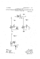
- FIG. 2 and 4 are two diagrams showing two ways of arranging the circuit at the receiving-station, and Fig. 3 is a diagram showing a way of arranging the circuit at the transmitting-station;
- the ball-microphone consists of two blocks K K furnished with cylindrical recess'esK and brought against one'another byslight mechanical pressure, as by a spring 0, and thus press along the circular edges of the recesses K against a' As the me ball R, located between them.
- chanical pressure is uniformlydistributed over two circular lines, this pressure may be made fairly large without soiiicreasing the specific pressure as ,to cause short-circuiting;
- a' colierer normally interrupts the. cireuit, while a microphone-receiver preserves'a permanently-closed circuit and merely varies the resistance in said circuit.
- a condenser m the receiving-circuit.
- S and Si have nolield that is common to both.
- S S1 would be the primary coil ofa trans former, the secondary coil of which would be connected with the terminals of the microphone.
- it would be p'ossi bleto effect an increase of the current strength by induction.
- FIG. 3 we have shown diagran'imatically the arrangement of parts that may be employed at the transmitting station.
- a B S E indicate a transmitter of the same electrical quality as thereceiver on which it is intended to act thatis, the transmitter should have such a self-induction and such'a capacity that its rate of oscillation willbe the same as in Fig. 3, of a condenser K and a spark-gap F.
- Thisbranch circuit should have the same rate of oscillation (that is the same product of self-induction and capacity) as the aerial conductorwith which it is connected; but the self-induction of the branch circuit should be smaller than that of the aerial conductor and the capacity larger than that of the aerial conductor.
- a microphone-receiver comprising two recessedconducting-bodies, and a conductingball located between said bodies and engaging them at their recesses;
- a receiving system vfor wireless-telegraphy which comprises an aerial conductor, adapted to receive the electrical impulses and connected to the earth, and a branch circuit connected with said aerial conductor, said branch circuit including a microphone and means for so transforming the energy received by the aerial conductor as to decrease the potential and increase the current.
- a receiving system for wireless telegraphy comprising an aerial conductor connected to the earth and a branch circuit connected with said ae'rial conductor and having a rate of oscillation equal to that of the aerial conductor, a microphone included in said branch circuit and means likewise included in the branch circuit, for so transforming the energ; received from the aerial conductor as to diminish the tension and increase the strength of the current.
- a transmitter for wireless telegraphy comprising a continuous aerial conductor connected with the earth, and an exciting branch circuit containing the spark-gap and connected with said aerial conductor and having the same product of self-induction and capacity as said conductor, the capacity of the branch circuit being larger than that of the aerial conductor and the self-induction of the branch circuit being correspondinglysmaller.
Landscapes
- Details Of Audible-Bandwidth Transducers (AREA)
Description
SLABY & e. G. ARGO. SYSTEM OF WIRELESS TELBGRAPHY WITH TUNED MICROPHONE RECEIVERS.
PATENTED MAR. 21, 1905.
. APPLIOATIONIILED MM. 27. 1901.
2 SHEBIS-SHEET 1.
I vwm /w I PATENTED MAR. 21, I905.
A. SLABY & G. G. ARGO. SYSTEM OI WIRELESS TELEGRAPHY WITH TUNED MICROPHONE RECEIVERS APPLICATION IILED SEPT. 27. 1901.
2 SHEETS-SHEET 2.
WITNEEEES. {j INVENTURS 62. MM rwzi fi f fiw $10 %%WO{{%L ATTDRNEYS' UNITED STATES Patented March 21, 1905.
PATENT OFFICE.
ADOLF SLABY, OF OHARLOTTENBURG, AND GEORG GRAF ARGO, OF
BERLIN, GERMANY.
SYSTEM OFWIRELESS TELEGRAPHY WITH TUN E D MICROPHONE-RECEIVERS.
SPECIFICATION forming art of Letters Patent Np. 785,276, dated Marcher, 1905.
Application filed September 27, 1901.1 Serial No. 76,813. A
To all wl mn, it may concern:
n Be it known-that we, ADOLF SLABY, res1d-,
ing at Sophienstrasse 4, Charlottenburg, and G none G'RAF ARoo, residing at Cuxhavenerstrasse 2, Berlin, Germany, subjects of the German Emperor, have invented certain new and useful Improvements in Systems of Wireless Telegraphy with Tuned Microphone-Receivers, of which the following is a specification.
Hitherto two different kinds of wave-indicators have been used as receiving apparatus in connection with wireless telegraphy. The more usual ofthe two is the coherer. "The peculiarity of the coherer is that its resistance (before it has been influenced) is infinite, and thus it represents a condenser of acapacity of about 0.0001 microfarad. After the instrument has been influenced the ohmic resistance varies between thirty and two thousand ohms.-
On account of the very considerable variation in the resistance it is possible through the medium of a relay to operate a Morse recording instrument, The return of the coherers resistance to inlinity is effected not automatically by the coherer, lint by means of a mechanical tapper.
The second kind of wave-indicators, which we havetermed microphone-receivers, are characterized by their possessing a relatively small resistance (thirty to iifty ohms) even before being influenced by the current, this resistance at starting being reduced about ten per cent, and after the efi'eet of the electric impulses has ceased returning to the original state of resistance without any mechanical shock. By reason, as mentioned,
of the veryslight variati'onof resistance a re-' laycannot beoperated, and-it is necessary, as
I is well known to use in connection with microphone receivers telephone receivers in' which a sound is heard corresponding in pitch or in number of vibrations with the frequency of the primary stream of sparks.
' Reference is to be had to the accompanyingdrawings, in which Figure 1 is a side elevation of the receiver we prefer to'employ. Fig. 1 is an enlarged view of the same with parts in section. Fig.
1 is a sectional elevation on line be of Fig;
13' Figs. 2 and 4 are two diagrams showing two ways of arranging the circuit at the receiving-station, and Fig. 3 is a diagram showing a way of arranging the circuit at the transmitting-station;
Among the .manyfpossible forms We have adopted that of the ball-microphone asthe most effective. The ball-microphone, Figs. 1, vI, and 1-, consists of two blocks K K furnished with cylindrical recess'esK and brought against one'another byslight mechanical pressure, as by a spring 0, and thus press along the circular edges of the recesses K against a' As the me ball R, located between them. chanical pressure is uniformlydistributed over two circular lines, this pressure may be made fairly large without soiiicreasing the specific pressure as ,to cause short-circuiting; The
microphone, therefore, is not affected by mechanical shocks. As metals between which the contact takes place we have found steel to be suitable for the ball and aluminium for the blocks.
As stated at the beginning of this specification, a' colierer normally interrupts the. cireuit, while a microphone-receiver preserves'a permanently-closed circuit and merely varies the resistance in said circuit. In order, therefore, to tun ethe microphonereceiving-circuit to a predetermined rate of oscillations, it becomes necessary to insert a condenser m the receiving-circuit. Furthermore, experiments havelshown that a mic'rophone-reeeiver re-- 1 sponds to variations of the current and not to variations of potential.
ieally'in' Fig. 2'. Suppose the vertical cont I For this reason we have included in that part'of the receivingof the condenser K, it is immaterial whetherthe microphone M be inserted between the point B and the coil S as in Fig. 2, or between the coilS and the condenser K, as in Fig. 4. By this-connecting arrangement not 3 only is the sensitiveness of the receiver considerably increased, but the atmospheric discharges, which otherwise have an exceedingly disturbing elfect, especially in microphonereceivers, are entirely avoided. Sincein this connecting arrangement the coil S is charged not only through the capacity of the air-conductor B A, but simultaneously through the condenser K, arranged in parallel thereto, if K be varied the oscillations of the vertical conductor also simultaneously vary, and if K be enlarged they'are retarded. This presents the drawback that with a given number ofoscillations of the transmitter the aerialconductor of the tuned receiver can only have a relatively small height. in order to prevent this, the connection shown in Fig. 4 is employed. According to this, the self-induction arrangement necessary for tuning the vertical conductor A B E is divided into two coils, and to the one S the tuned receiver system is connected, as in Fig. 2, while the other part, Sl, is employed only for tuning the open oscillation-circuit. S and Si have nolield that is common to both. The same effect can, moreover, be secured if the secondary system, containing the microphone, is actuated not by charging, but by induction. In the latter case S S1 would be the primary coil ofa trans former, the secondary coil of which would be connected with the terminals of the microphone. Thus in this case it would be p'ossi bleto effect an increase of the current strength by induction.
In Fig. 3 we have shown diagran'imatically the arrangement of parts that may be employed at the transmitting station. in Fig. 3, A B S E indicate a transmitter of the same electrical quality as thereceiver on which it is intended to act thatis, the transmitter should have such a self-induction and such'a capacity that its rate of oscillation willbe the same as in Fig. 3, of a condenser K and a spark-gap F. Thisbranch circuit should have the same rate of oscillation (that is the same product of self-induction and capacity) as the aerial conductorwith which it is connected; but the self-induction of the branch circuit should be smaller than that of the aerial conductor and the capacity larger than that of the aerial conductor. With this arrangement we are onabled to supply a considerable amount of' energyto the exciting system, and the vibrations of the aerial transmitting-wire will be damped but" very slightly. In tuning the transmitter according to Fig. 3 the simplest plan is to insert the microphone in the exciting-circuit instead of connecting the spark-- gap F to the receiver. The transmitter and the receiver are in this case absolutely congruent and exactly tuned. It will be understood that the coil S in Fig. 3 serves to regulate the rate of vibration of the transmittingwire.
Having described our invention, what we claim, and desire to secure by Letters Patent, 1s
1. A microphone-receiver comprising two recessedconducting-bodies, and a conductingball located between said bodies and engaging them at their recesses;
2. A receiving system vfor wireless-telegraphy which comprises an aerial conductor, adapted to receive the electrical impulses and connected to the earth, and a branch circuit connected with said aerial conductor, said branch circuit including a microphone and means for so transforming the energy received by the aerial conductor as to decrease the potential and increase the current.
3. A receiving system for wireless telegraphy, comprising an aerial conductor connected to the earth and a branch circuit connected with said ae'rial conductor and having a rate of oscillation equal to that of the aerial conductor, a microphone included in said branch circuit and means likewise included in the branch circuit, for so transforming the energ; received from the aerial conductor as to diminish the tension and increase the strength of the current.
4. A transmitter for wireless telegraphy comprising a continuous aerial conductor connected with the earth, and an exciting branch circuit containing the spark-gap and connected with said aerial conductor and having the same product of self-induction and capacity as said conductor, the capacity of the branch circuit being larger than that of the aerial conductor and the self-induction of the branch circuit being correspondinglysmaller.
ADOLF SLABY. GEORG (iRAF ARGO.
Witnesses;
WOLDEMAR HAur'r, HENRY HASPER.
Priority Applications (1)
| Application Number | Priority Date | Filing Date | Title |
|---|---|---|---|
| US7681301A US785276A (en) | 1901-09-27 | 1901-09-27 | System of wireless telegraphy with tuned microphone-receivers. |
Applications Claiming Priority (1)
| Application Number | Priority Date | Filing Date | Title |
|---|---|---|---|
| US7681301A US785276A (en) | 1901-09-27 | 1901-09-27 | System of wireless telegraphy with tuned microphone-receivers. |
Publications (1)
| Publication Number | Publication Date |
|---|---|
| US785276A true US785276A (en) | 1905-03-21 |
Family
ID=2853768
Family Applications (1)
| Application Number | Title | Priority Date | Filing Date |
|---|---|---|---|
| US7681301A Expired - Lifetime US785276A (en) | 1901-09-27 | 1901-09-27 | System of wireless telegraphy with tuned microphone-receivers. |
Country Status (1)
| Country | Link |
|---|---|
| US (1) | US785276A (en) |
Cited By (1)
| Publication number | Priority date | Publication date | Assignee | Title |
|---|---|---|---|---|
| US20070105770A1 (en) * | 2004-01-21 | 2007-05-10 | Novo Nordisk A/S | Transglutaminase mediated conjugation of peptides |
-
1901
- 1901-09-27 US US7681301A patent/US785276A/en not_active Expired - Lifetime
Cited By (1)
| Publication number | Priority date | Publication date | Assignee | Title |
|---|---|---|---|---|
| US20070105770A1 (en) * | 2004-01-21 | 2007-05-10 | Novo Nordisk A/S | Transglutaminase mediated conjugation of peptides |
Similar Documents
| Publication | Publication Date | Title |
|---|---|---|
| US2211750A (en) | Wireless telegraph system | |
| US785276A (en) | System of wireless telegraphy with tuned microphone-receivers. | |
| US2243118A (en) | Automatic antenna switching diversity system | |
| US1896065A (en) | Selective circuit for superheterodyne radioreceivers | |
| US1876163A (en) | Wave signaling system | |
| US1811963A (en) | Apparatus for reducing crosstalk currents | |
| US1655537A (en) | Amplifier circuits | |
| US706747A (en) | Apparatus for signaling by electromagnetic waves. | |
| US768004A (en) | Space telegraphy. | |
| US1687933A (en) | Electrical signaling system | |
| US1628676A (en) | Receiving arrangement for wireless telegraphy | |
| US1962155A (en) | Vibratory system and apparatus | |
| US956165A (en) | Electrical space communication. | |
| US1318342A (en) | John hays hammond | |
| US753863A (en) | Wireless signaling. | |
| US767982A (en) | Space telegraphy. | |
| US1558231A (en) | Multiplex telegraphy | |
| US1748730A (en) | Radio receiving system | |
| US1507887A (en) | lubjslioo | |
| US1223376A (en) | Wireless receiving system. | |
| US1350911A (en) | Wireless signaling system | |
| US1224342A (en) | Multiplex telegraphy. | |
| US1371228A (en) | Reduction of static interference in radioreceiving stations | |
| US786132A (en) | Wireless telegraphy. | |
| US767994A (en) | Space telegraphy. |