US7686721B2 - Bicycle chainring - Google Patents
Bicycle chainring Download PDFInfo
- Publication number
- US7686721B2 US7686721B2 US11/126,143 US12614305A US7686721B2 US 7686721 B2 US7686721 B2 US 7686721B2 US 12614305 A US12614305 A US 12614305A US 7686721 B2 US7686721 B2 US 7686721B2
- Authority
- US
- United States
- Prior art keywords
- chainring
- set forth
- bicycle
- bicycle chainring
- members
- Prior art date
- Legal status (The legal status is an assumption and is not a legal conclusion. Google has not performed a legal analysis and makes no representation as to the accuracy of the status listed.)
- Expired - Fee Related, expires
Links
Images


Classifications
-
- B—PERFORMING OPERATIONS; TRANSPORTING
- B62—LAND VEHICLES FOR TRAVELLING OTHERWISE THAN ON RAILS
- B62M—RIDER PROPULSION OF WHEELED VEHICLES OR SLEDGES; POWERED PROPULSION OF SLEDGES OR SINGLE-TRACK CYCLES; TRANSMISSIONS SPECIALLY ADAPTED FOR SUCH VEHICLES
- B62M9/00—Transmissions characterised by use of an endless chain, belt, or the like
- B62M9/04—Transmissions characterised by use of an endless chain, belt, or the like of changeable ratio
- B62M9/06—Transmissions characterised by use of an endless chain, belt, or the like of changeable ratio using a single chain, belt, or the like
- B62M9/10—Transmissions characterised by use of an endless chain, belt, or the like of changeable ratio using a single chain, belt, or the like involving different-sized wheels, e.g. rear sprocket chain wheels selectively engaged by the chain, belt, or the like
- B62M9/105—Transmissions characterised by use of an endless chain, belt, or the like of changeable ratio using a single chain, belt, or the like involving different-sized wheels, e.g. rear sprocket chain wheels selectively engaged by the chain, belt, or the like involving front sprocket chain-wheels engaged by the chain, belt or the like
Definitions
- This invention generally relates to a bicycle chainring. More specifically, the present invention relates to a bicycle chainwheel that is made of at least two attached annular portions.
- the chain engaging gears of the bicycle have been re-shaped to reduce friction and have been made more light weight to reduce the total mass of the bicycle.
- the chain engaging gears contribute a measurable amount of weight to the bicycle.
- Another object of the present invention is to provide bicycle chainring gear that has a reduction in transmission of noise when riding, making the ride smoother and quieter.
- FIG. 1 is a side elevation of a bicycle with a crank assembly that includes a composite bicycle chainring in accordance with a first embodiment of the present invention
- FIG. 2 is an enlarged side elevation of the crank assembly shown removed from the bicycle depicted in FIG. 1 , and including the composite bicycle chainring in accordance with the present invention
- FIG. 3 is a perspective view of the crank assembly depicted in FIG. 2 , showing the composite bicycle chainring and the crank assembly in accordance with the present invention
- FIG. 6 is a side elevation of the composite bicycle chainring shown removed from the crank assembly in accordance with the present invention.
- FIG. 7 is a cross-sectional view of a portion of the composite bicycle chainring taken along the line 7 - 7 in FIG. 6 in accordance with the present invention.
- FIG. 8 is a cross-sectional view of another portion of the composite bicycle chainring taken along the line 8 - 8 in FIG. 6 in accordance with the present invention.
- FIG. 9 is a cross-sectional view of still another portion of the composite bicycle chainring taken along the line 9 - 9 in FIG. 6 in accordance with the present invention.
- FIG. 14 is an end view showing a edge of the second member of the composite bicycle chainring in accordance with the present invention.
- FIG. 15 is an exploded perspective view showing a portion of the second side of the first member being assembled to the second side of the second member using first and second fastening tubular members in order to form the composite bicycle chainring in accordance with the present invention
- FIG. 16 is an exploded perspective view similar to FIG. 15 showing a portion of the first side of the second member being assembled to the first side of the first member using the first and second fastening tubular members in order to form the composite bicycle chainring in accordance with the present invention
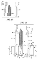
- FIG. 17 is an exploded cross-sectional view of the portion of the composite bicycle chainring depicted in FIG. 7 in accordance with the present invention.
- FIG. 18 is an exploded cross-sectional view of the portion of the composite bicycle chainring depicted in FIG. 8 in accordance with the present invention.
- FIG. 19 is a cross-sectional view of a portion of the composite bicycle chainring taken along the line 19 - 19 in FIG. 11 in accordance with the present invention.
- FIG. 20 is another cross-sectional view of a portion of the composite bicycle chainring taken along the line 20 - 20 in FIG. 11 in accordance with the present invention
- FIG. 21 is a fragmentary cross-sectional view of a bicycle with a crank assembly that includes a composite bicycle chainring in accordance with a second embodiment of the present invention.
- FIG. 22 is an exploded perspective view of the composite bicycle chainring depicted in FIG. 21 , showing a first member and an second member of the composite bicycle chainring in accordance with the second embodiment of the present invention
- FIG. 23 is a side elevation of the composite bicycle chainring shown removed from the crank assembly in accordance with the second embodiment of the present invention.
- FIG. 24 is a fragmentary perspective view showing a portion of a first member of a composite bicycle chainring in accordance with a third embodiment of the present invention.
- FIG. 25 is a fragmentary perspective view showing a portion of a second member of the composite bicycle chainring in accordance with the third embodiment of the present invention.
- FIG. 26 is a fragmentary perspective view showing a portion of the first and second members of the composite bicycle chainring in accordance with the third embodiment of the present invention.
- FIG. 27 is a fragmentary cross-sectional view of the composite bicycle chainring taken along the line 27 - 27 in FIG. 26 , in accordance with the third embodiment of the present invention.
- FIG. 28 is a fragmentary perspective view showing a portion of a first member of a composite bicycle chainring in accordance with a fourth embodiment of the present invention.
- FIG. 29 is a fragmentary perspective view showing a portion of a second member of the composite bicycle chainring in accordance with the fourth embodiment of the present invention.
- FIG. 30 is a fragmentary perspective view showing a portion of the first and second members of the composite bicycle chainring in accordance with the fourth embodiment of the present invention.
- FIG. 31 is a fragmentary cross-sectional view of the composite bicycle chainring taken along the line 31 - 31 in FIG. 30 , in accordance with the third embodiment of the present invention.
- a bicycle 10 is illustrated that is fitted with a crank assembly 12 that includes a composite bicycle chainring 14 in accordance with the first embodiment of the present invention.
- the composite bicycle chainring 14 of the present invention is a light weight chainring that includes a plurality of elements fixed to one another, as is described in greater detail below.
- the bicycle crank assembly 12 basically includes a first crank arm 16 supported on a shaft 18 ( FIG. 3 ).
- the first crank arm 16 is formed with a plurality of conventional support of portions 20 ( FIGS. 2-4 ).
- each of the support portions 20 include a chainring mounting aperture 22 , a circumferentially extending surface 24 and radially extending surface 26 .
- the chainring mounting apertures 22 are generally equidistantly spaced apart from the shaft 18 and each other along with corresponding circumferentially extending surfaces 24 and radially extending surfaces 26 which are formed in a conventional manner.
- the bicycle chainring 12 is installed on the first crank arm 16 by fasteners F and threaded nuts N.
- the fasteners F extend through apertures formed in the bicycle chainring 12 and through the chainring mounting apertures 22 where the fasteners F then thread into the threaded nuts N.
- the bicycle chainring 12 basically includes a first member 28 , a second member 30 , a non-metallic filler material 32 and a plurality of tubular members, including a plurality of first fastening members 34 and a plurality of second fastening members 36 .
- the first member 28 and the second member 30 are fixedly attached to one another with the non-metallic filler material 32 sandwiched in between, as shown in FIGS. 6-9 and described in greater detail below.
- the first member 28 is basically an annular shaped member that is configured to rotate about a center rotational axis C.
- the center rotational axis C coincides with the shaft 18 with the first member 28 installed on the support portions 20 of the first crank arm 16 , as indicated in FIG. 4 .
- the first member 28 is formed with a crank attachment portion 40 and an annular tooth portion 42 .
- the first member 28 also has a first side 44 ( FIG. 10 ) and a second side 46 ( FIG. 11 ).
- the crank attachment portion 40 is formed with an outer annular part 48 having a plurality of radially inward extending parts 50 .
- Each of the radially inward extending parts 50 is formed with a corresponding chainring attachment opening 52 and a circumferentially extending surface 54 .
- Each of the chainring attachment opening 52 extends from the first side 44 to the second side 46 , as shown in FIG. 8 . Further, each of the chainring attachment openings 52 is formed with a diameter D 1 .
- Each of the circumferentially extending surfaces 54 is shaped to correspond to the shape of the circumferentially extending surfaces 24 of the crank arm 16 .
- each of the circumferentially extending surfaces 54 of the radially inward extending parts 50 of the first member portion 40 faces and can contact the circumferentially extending surfaces 24 of the crank arm 16 .
- annular recess 56 is formed on the first side 44 of the first member 28 around each of the chainring attachment openings 52 of the radially inward extending parts 50 .
- Each of the annular recesses 56 is formed with a diameter D 2 .
- the annular tooth portion 42 of the first member 28 is located radially outward from the outer annular part 48 of the crank attachment portion 40 of the first member 28 .
- the annular tooth portion 42 is formed with a plurality of chain engaging gear teeth 58 and a plurality of first fastening apertures 59 .
- the chain engaging gear teeth 58 define an outer diameter D 3 of the first member 28 , as shown in FIG. 10 .
- An inner radial edge of the outer annular part 48 defines an inner diameter D 4 the first member 28 , as shown in FIG. 11 .
- the first member 28 is provided with spike rivets S 1 and S 2 .
- spike rivets S 1 and S 2 are installed on the composite bicycle chainring 14 at spaced apart location.
- Each spike rivet S 1 includes a protrusion that assists in guiding a chain (not shown) during gear shifting in a manner known in the art.
- the spike rivets S 1 are installed in selected ones of the first fastening apertures 59 , as shown in FIGS. 11 and 20 .
- the spike rivets S 2 are similarly installed at locations radially inward of the spike rivets S 1 , as is indicated in FIGS. 11 and 19 .
- the embodiment of the present invention depicted in the drawings includes four radially inward extending parts 50 of the first member 28 , four radially inward extending parts 64 of the second member 30 , four first fastening members 34 and four second fastening members 36 , all of which attach to the four support portions 20 of the crank assembly 12 .
- the composite bicycle chainring 14 can alternatively be made with any number of these mentioned elements.
- Each of the radially inward extending parts 64 is formed with a chainring attachment opening 67 that has an inner diameter D 5 , as shown in FIG. 13 . Further, each radially inward extending part 64 is formed with a circumferentially extending surface 68 that is shaped to correspond to the shape of the circumferentially extending surfaces 24 of the crank arm 16 . Specifically, then the composite bicycle chainring 14 is installed on the crank arm 16 , each of the circumferentially extending surfaces 68 of the second member 30 faces and can contact the circumferentially extending surfaces 24 of the crank arm 16 .
- a portion of the inner peripheral portion 60 further defines an inner diameter D 6 of the second member 30 , as shown in FIG. 13 .
- the inner diameter D 6 of the second member 30 is preferably approximately equal to the inner diameter D 4 the first member 28 .
- the inner periphery portion 60 of second member 30 is formed with a continuous axially extending wall 70 that extends from the second side 65 and away from the first side 66 of the second member 30 .
- the axially extending wall 70 further extends along the edge of the inner peripheral portion 60 , and extends uninterrupted along each of the radially inward extending parts 64 , as shown in FIGS. 7-9 , 12 and 14 - 16 .
- the outer peripheral portion 62 has a uniform outer radial edge and is formed with a plurality of second outer fastening apertures 72 that are spaced slightly radially inward from the outer radial edge. As shown in FIGS. 4 , 5 and 7 - 9 , the outer peripheral portion 62 of the second member 30 is bonded to the annular tooth portion 42 of the first member 28 . The bonding between the outer peripheral portion 62 of the second member 30 and the annular tooth portion 42 of the first member 28 can be accomplished using rivets 74 , an adhesive or any of a variety of welding techniques.
- the rivets 74 are inserted into the first outer fastening apertures 59 in the first member 28 and through the second outer fastening apertures 72 of the second member 30 and deformed to secure the composite bicycle chainring 14 together. It should be understood from the drawings and description herein that the rivets 74 and the spike rivets S 1 are attached in generally the same manner. Further, the spike rivets S 1 are used in place of the rivets 74 at desired locations to fix the first member 28 to the second member 30 .
- the first member 28 and the second member 30 are fixedly attached to one another such that the radially extending parts 64 of the inner peripheral portion 60 of the second member 30 overlie radially inwardly extending parts 50 of the crank attachment portion 40 of the first member 28 . Further, the outer peripheral portion 62 of the second member 30 overlies a radially inner part of the annular tooth portion 42 radially inward of the chain engaging gear teeth 58 .
- the first member 28 and the second member 30 are further fixedly attached to one another such that without obstructing access to chainring attachment openings 52 and 67 .
- the chainring attachment openings 52 and 67 are preferably axially aligned with one another.
- the diameter D 1 of each of the chainring attachment openings 52 of the first member 28 is smaller that the diameter D 5 of the chainring attachment openings 67 of the second member 30 .
- the diameter D 2 of each of the annular recesses 56 of the first member 28 is approximately the same or slightly smaller that the diameter D 5 of the chainring attachment openings 67 of the second member 30 .
- the inner peripheral portion 60 of the second member 30 has generally the same profile or shape as the crank attachment portion 40 of the first member 28 .
- the radially inward extending parts 50 of the first member 28 and the radially inward extending parts 64 of the second member 30 have the same overall contour and shape and can overlie each other. Consequently, the inner peripheral portion 60 of the second member 30 overlies and conforms to the shape of the crank attachment portion 40 of the first member 28 to form an interior space S ( FIGS. 7-9 ) between the second member 30 and the first member 28 .
- the first member 28 is preferably made of a hard metallic material, such as a steel alloy or other metal alloy that has been provided with a hardened outer surface. Specifically, the first member 28 can be subjected to a conventional surface hardening process.
- the second member 30 is preferably formed without a surface hardening treatment, at least in the first embodiment. Consequently, the second member 30 is made from a material that is softer than the material of the first member 28 .
- the second member 30 can alternatively be provided with a surface hardening treatment, depending on desired properties and intended use of the present invention.
- the non-metallic filler material 32 is preferably a resilient rubber or rubber-like material that is inserted into the interior space S created between the second side 65 of the second member 30 and the first side 44 of the first member 28 .
- the non-metallic filler material 32 can be made of any of a variety of materials that provide sound and/or vibration dampening, such as various foam materials, plastics, polymers or rubber-based materials.
- the plurality of first fastening members 34 are tubular members best shown in FIGS. 15 , 16 and 18 .
- Each of the first fastening members 34 includes two hollow portions, a main body portion 76 and a recessed portion 78 .
- the main body portion 76 has an inner diameter D 6 and an outer cover abutment surface 79 .
- the recessed portion 78 has an inner diameter D 7 that is smaller than the inner diameter D 6 .
- the recessed portion 78 is formed with a two abutment surfaces 80 and 82 .
- the abutment surface 80 is dimensioned to contact the first side 44 of the first member 28 when the first fastening member 34 is inserted into the chainring attachment opening 52 .
- the abutment surface 82 of the recessed portion 78 has an outer diameter that is generally the same as the diameter D 2 of the annular recess 56 around the chainring attachment opening 52 . Therefore, when the first fastening members 34 are inserted into corresponding chainring attachment openings 52 , the abutment surface 82 engages the surface of the annular recess 56 centering the first fastening members 34 and restricting movement thereof. Further, the inner diameter D 6 of the first fastening members 34 is approximately the same size or slightly larger than the diameter D 5 of the chainring attachment opening 67 .
- each of the first fastening members 34 is inserted into respective ones of the annular recess 56 of the radially inward extending parts 50 of the first member 28 .
- the outer cover abutment surfaces 79 of the first fastening members 34 contact the second side 65 of the second member 30 in the region around the chainring attachment openings 67 .
- the plurality of second fastening members 36 are also tubular members that are best shown in FIGS. 15 , 16 and 18 .
- Each of the second fastening members 36 includes two hollow portions, a main body portion 84 and an abutment portion 86 .
- the main body portion 84 has an outer diameter that is approximately the same or slightly smaller than each of the inner diameter D 6 of the main body portion 76 of the first fastener members 34 and the diameter D 5 of the chainring attachment openings 67 of the second member 30 .
- the main body portion 84 has an outer diameter that allows the second fastener members 36 to be inserted into or nested within the first fastening members 34 .
- the abutment portion 86 has an outer diameter D 8 that is larger than the inner diameter D 5 of the chainring attachment openings 67 of the second member 30 .
- the abutment portion 86 includes an abutment surface 88 .
- the main body portion 84 of each of the second fastening members 36 is inserted into respective ones of the chainring attachment openings 67 of the second member 30 . Further, the main body portion 84 of each of the second fastening members 36 concentrically extends into the hollow interior of corresponding main body portions 76 of the first fastening members 34 . Lastly, the abutment surface 88 of the abutment portion 86 is brought into contact with the first side 66 of the second member 30 in the area around the chainring attachment openings 67 of the second member 30 to complete the basic assembly of the composite bicycle chainring 14 with the first and second fastening members 34 and 36 .
- the second member 30 and the first member 28 are fixedly coupled together by a plurality of the first and second fastening members 34 and 36 (tubular fastening members).
- the chainring attachment openings 52 of the first member 28 are brought into alignment with the chainring attachment openings 67 of the second member 30 . Consequently, the first and second fastening members 34 and 36 are axially aligned with respective ones of the chainring attachment openings 52 and the chainring attachment openings 67 .
- crank assembly 112 that includes a bicycle chainring 114 in accordance with a second embodiment of the present invention will now be explained.
- the parts of the second embodiment that are identical to the parts of the first embodiment will be given the same reference numerals as the parts of the first embodiment.
- the descriptions of the parts of the second embodiment that are identical to the parts of the first embodiment may be omitted for the sake of brevity.
- the parts of the second embodiment that differ slightly from the parts of the first embodiment will be indicated with a single prime (′) or will be provided with a new reference numeral.
- the crank assembly 112 is generally configured for use with a bicycle that only includes a single gear element at the front portion of the drive train of the bicycle. Specifically, the crank assembly 112 includes the bicycle chainring 114 without other gears or chainrings.
- the crank assembly 112 basically includes crank arms 116 and a shaft 118 that extends between the crank arms 116 .
- One of the crank arms 116 includes a threaded aperture 122 that receives a single fastener 124 .
- the bicycle chainring 114 basically includes a first member 128 , an second member 130 , a non-metallic filler material 132 , a single first fastening member 34 ′ and a single second fastening member 36 ′ and a large pair of tubular members including a third fastening member 134 and a fourth fastening member 136 .
- the first member 128 and the annular outer cover 130 are fixedly attached to one another with the non-metallic filler material 132 sandwiched in between.
- the first member 128 is similar to the first member 28 of the first embodiment, except that the first member 128 is formed with a central opening 152 and a single attachment opening 52 ′.
- the central opening 152 is formed with an annular recess 156 .
- the single attachment opening 52 ′ is formed with an annular recess 56 ′ that is the same as the annular recess 56 in the first embodiment.
- the first member 128 of the second embodiment is formed with an annular tooth portion 42 and a plurality of chain engaging gear teeth 58 .
- the annular recess 56 ′ is dimensioned to receive the recessed portion 78 ′ of the first fastening member 34 ′ in a manner similar to the first embodiment.
- the second member 130 is generally the same as the second member 30 of the first embodiment, except that the second member 130 is formed with a central opening 167 and a single attachment opening 67 ′.
- the non-metallic filler material 132 is generally the same as the non-metallic filler material 32 of the first embodiment except that the non-metallic filler material 132 is larger in order to fill the space between the first member 128 and the second member 130 .
- the first fastening member 34 ′ is formed with the recessed portion 78 ′ that is fitted into the annular recess 56 ′ about the attachment opening 52 ′ in the first member 128 .
- the second fastening member 36 ′ is installed in the single attachment opening 67 ′ in the second member 130 and further extends into the hollow interior of the first fastening member 34 ′.
- the second fastening member 36 ′ can be permanently fixed or bonded to the first fastening member 34 ′ by any of a variety of attachment methods, such as deformation, bonding by adhesive or welding techniques.
- the third fastening member 134 has an outer diameter that is larger than the first fastening member 34 ′ but has a configuration similar to the first fastening member 34 ′.
- the third fastening member 134 includes a recessed portion 178 that is dimensioned to fit into the annular recess 156 formed about the central opening 152 in the first member 128 .
- the fourth fastening member 136 is formed with a main body portion 184 and an abutment portion 186 in a manner similar to the second fastening member 36 ′ and the second fastening members 36 of the first embodiment.
- the main body portion 184 of the fourth fastening member 136 is fitted into the central opening 167 of the second member 130 , and into the hollow interior of the third fastening member 134 .
- the fourth fastening member 136 can be permanently fixed or bonded to the third fastening member 134 by any of a variety of attachment methods, such as deformation, bonding by adhesive or welding techniques.
- the fourth fastening member 136 is formed with an inner diameter that is approximately the same as the outer diameter of the shaft 118 .
- the bicycle chainring 114 is installed on the crank assembly 112 as shown in FIG. 21 .
- the shaft 118 is fitted into the hollow interiors of the fourth fastening members 136 such that the bicycle chainring 114 rotates with the shaft 118 .
- the bicycle chainring 114 is fixed for rotation with the shaft 118 by installation of the single fastener 124 through the second fastener second fastening member 36 ′ and into the threaded aperture 122 on the crank arm 116 .
- FIGS. 24 , 25 , 26 and 27 a bicycle chainring 214 in accordance with a third embodiment of the present invention will now be explained.
- the parts of the third embodiment that are identical to the parts of the first or second embodiments will be given the same reference numerals as the parts of the first or second embodiments.
- the descriptions of the parts of the third embodiment that are identical to the parts of the first or second embodiment may be omitted for the sake of brevity.
- the bicycle chainring 214 basically includes a first member 228 and a second member 230 .
- the first member 228 includes a plurality of radially inward extending parts 50 ′ (although only one is shown), a plurality of spaced apart gear teeth 258 , recesses 260 and an axially extending wall 70 ′.
- Each of the radially inward extending parts 50 ′ is formed with a chainring attachment opening 52 that is encircled by an annular recess 56 .
- the plurality of spaced apart gear teeth 258 and the recesses 260 alternate around the outer periphery of the first member 228 .
- the axially extending wall 70 ′ is operably the same as the axially extending wall 70 described above with respect to the first embodiment.
- the second member 230 is formed with a plurality of radially inward extending parts 64 ′ (although only one is shown) and a plurality of spaced apart gear teeth 268 that are separated from one another by radially extending surfaces 270 .
- Each extending part 64 ′ is formed with chainring attachment openings 67 , as in the first embodiment.
- the bicycle chainring 214 includes non-metallic filler material and first and second fastening members 34 and 36 which engage annular recess 56 and the chainring attachment openings 67 of the first and second members 228 and 230 , respectively, in a manner generally the same as in the first embodiment.
- FIGS. 28 , 29 , 30 and 31 a bicycle chainring 314 in accordance with a fourth embodiment of the present invention will now be explained.
- the parts of the fourth embodiment that are identical to the parts of the first embodiment will be given the same reference numerals as the parts of the first embodiment.
- the descriptions of the parts of the fourth embodiment that are identical to the parts of the first embodiment may be omitted for the sake of brevity.
- the bicycle chainring 314 basically includes a first member 328 and a second member 330 .
- the first member 328 is formed with a plurality of gear teeth 58 , a plurality of fastening apertures 59 ′′ and an annular axially extending wall 70 ′′.
- the second member 330 is formed with a plurality of fastening apertures 72 ′′ and a plurality of radially inward extending parts 64 ′′ that include chainring attachment openings 67 ′′.
- the first and second members 328 and 330 are fixed together by rivets (not shown) that extend through the respective fastening apertures 59 ′′ and 72 ′′.
- a non-metallic filler material (not shown) is installed between the first and second members 328 and 330 .
- the bicycle chainring 314 is installed onto a crank assembly (not shown) by fasteners that extend through the chainring attachment openings 67 ′′.
- the term “comprising” and its derivatives, as used herein, are intended to be open ended terms that specify the presence of the stated features, elements, components, groups, integers, and/or steps, but do not exclude the presence of other unstated features, elements, components, groups, integers and/or steps.
- the foregoing also applies to words having similar meanings such as the terms, “including”, “having” and their derivatives.
- the terms “member” or “element” when used in the singular can have the dual meaning of a single part or a plurality of parts.
Landscapes
- Engineering & Computer Science (AREA)
- Chemical & Material Sciences (AREA)
- Combustion & Propulsion (AREA)
- Transportation (AREA)
- Mechanical Engineering (AREA)
- Gears, Cams (AREA)
- Axle Suspensions And Sidecars For Cycles (AREA)
- Devices For Conveying Motion By Means Of Endless Flexible Members (AREA)
Abstract
Description
Claims (24)
Priority Applications (5)
| Application Number | Priority Date | Filing Date | Title |
|---|---|---|---|
| US11/126,143 US7686721B2 (en) | 2005-05-11 | 2005-05-11 | Bicycle chainring |
| TW094138624A TWI277573B (en) | 2005-05-11 | 2005-11-03 | Bicycle chainring |
| BRPI0600367-2A BRPI0600367A (en) | 2005-05-11 | 2006-02-10 | larger bike crown |
| CNB2006100041172A CN100460273C (en) | 2005-05-11 | 2006-02-20 | Bicycle chainring |
| EP06009261A EP1721821B1 (en) | 2005-05-11 | 2006-05-04 | Bicycle chainring |
Applications Claiming Priority (1)
| Application Number | Priority Date | Filing Date | Title |
|---|---|---|---|
| US11/126,143 US7686721B2 (en) | 2005-05-11 | 2005-05-11 | Bicycle chainring |
Publications (2)
| Publication Number | Publication Date |
|---|---|
| US20060258498A1 US20060258498A1 (en) | 2006-11-16 |
| US7686721B2 true US7686721B2 (en) | 2010-03-30 |
Family
ID=36562968
Family Applications (1)
| Application Number | Title | Priority Date | Filing Date |
|---|---|---|---|
| US11/126,143 Expired - Fee Related US7686721B2 (en) | 2005-05-11 | 2005-05-11 | Bicycle chainring |
Country Status (5)
| Country | Link |
|---|---|
| US (1) | US7686721B2 (en) |
| EP (1) | EP1721821B1 (en) |
| CN (1) | CN100460273C (en) |
| BR (1) | BRPI0600367A (en) |
| TW (1) | TWI277573B (en) |
Cited By (37)
| Publication number | Priority date | Publication date | Assignee | Title |
|---|---|---|---|---|
| US20080312799A1 (en) * | 2007-06-12 | 2008-12-18 | Campagnolo S.R.L. | Method for electronically controlling a bicycle gearshift and bicycle electronic system |
| US20130087013A1 (en) * | 2011-10-05 | 2013-04-11 | Shimano Inc. | Bicycle sprocket |
| US20140162821A1 (en) * | 2012-07-09 | 2014-06-12 | Sram Deutschland Gmbh | Jockey Wheel for a Rear Derailleur in a Bicycle Gear System and Rear Derailleur with such a Jockey Wheel |
| US9062758B2 (en) | 2011-12-06 | 2015-06-23 | Sram, Llc | Chainring |
| US20150198231A1 (en) * | 2014-01-14 | 2015-07-16 | Shimano Inc. | Bicycle sprocket |
| US20150239528A1 (en) * | 2014-02-27 | 2015-08-27 | Eko Sport, Inc. | Alternating tooth chain ring |
| US20150285362A1 (en) * | 2014-04-08 | 2015-10-08 | Wolf Tooth Components, LLC | Sprocket |
| US9182027B2 (en) | 2011-12-06 | 2015-11-10 | Sram, Llc | Chainring |
| USD750998S1 (en) * | 2014-12-19 | 2016-03-08 | John Wang | Sprocket |
| USD750999S1 (en) * | 2014-07-24 | 2016-03-08 | Pendix Gmbh | Electric bicycle drive |
| US9394986B2 (en) | 2014-02-10 | 2016-07-19 | Wolf Tooth Components, LLC | Sprocket |
| US9394987B2 (en) | 2014-02-10 | 2016-07-19 | Wolf Tooth Components, LLC | Sprocket |
| USD774987S1 (en) * | 2015-04-01 | 2016-12-27 | Tien Hsin Industries Co., Ltd. | Bicycle sprocket |
| US9581230B2 (en) | 2014-02-10 | 2017-02-28 | Wolf Tooth Components, LLC | Sprocket |
| US9581231B2 (en) | 2014-04-08 | 2017-02-28 | Wolf Tooth Components, LLC | Sprocket |
| US9581229B2 (en) | 2014-02-10 | 2017-02-28 | Wolf Tooth Components, LLC | Sprocket |
| US9625027B2 (en) | 2014-04-08 | 2017-04-18 | Wolf Tooth Components, LLC | Sprocket |
| US20170146109A1 (en) * | 2015-07-03 | 2017-05-25 | Sram Deutschland Gmbh | Sprocket wheel for a bicycle drive |
| US9719590B2 (en) | 2013-06-05 | 2017-08-01 | Sram Deutschland Gmbh | Chainring |
| US9771128B2 (en) * | 2011-10-05 | 2017-09-26 | Shimano Inc. | Bicycle crank assembly |
| USD801876S1 (en) * | 2015-08-24 | 2017-11-07 | Robert Bosch Gmbh | Bicycle drive unit |
| US10093389B2 (en) * | 2016-11-16 | 2018-10-09 | Shimano Inc. | Bicycle front sprocket, bicycle crank assembly, and bicycle drive train |
| US10260568B2 (en) * | 2016-05-24 | 2019-04-16 | Glory Precision Industry Co., Ltd. | Connecting device for chainring of bicycle |
| US20190277386A1 (en) * | 2018-03-08 | 2019-09-12 | Shimano, Inc. | Bicycle sprocket |
| US10451166B2 (en) | 2015-04-13 | 2019-10-22 | Eko Sport, Inc. | Chain ring with teeth oppositely laterally engaging a drive chain |
| US20200011408A1 (en) * | 2018-07-06 | 2020-01-09 | Shimano Inc. | Bicycle sprocket |
| US10703441B2 (en) | 2015-07-03 | 2020-07-07 | Sram Deutschland Gmbh | Drive arrangement for a bicycle |
| US10800482B2 (en) | 2009-04-29 | 2020-10-13 | Fox Factory, Inc. | Bicycle crank arm and insert therefore |
| US11009112B2 (en) | 2016-04-11 | 2021-05-18 | Fox Factory, Inc. | Bicycle front sprocket |
| US11014628B2 (en) | 2017-04-28 | 2021-05-25 | Fox Factory, Inc. | Cinch direct mount 2X ring system |
| US20210277986A1 (en) * | 2018-08-09 | 2021-09-09 | James Hobbs | Apparatus for securing a sprocket to a sprocket carrier |
| US11292555B2 (en) * | 2018-08-01 | 2022-04-05 | Shimano Inc. | Bicycle sprocket |
| US11359709B2 (en) | 2018-12-18 | 2022-06-14 | Fox Factory, Inc. | Chainring |
| US11680633B2 (en) * | 2019-02-08 | 2023-06-20 | Fox Factory, Inc. | Chainring |
| US20230331340A1 (en) * | 2022-04-14 | 2023-10-19 | Shimano Inc. | Crank assembly for human powered vehicle |
| US20240101214A1 (en) * | 2022-09-28 | 2024-03-28 | Sram, Llc | Front chainring assembly |
| US12145691B2 (en) | 2021-05-25 | 2024-11-19 | Fox Factory, Inc. | Crank impact and wear protection article |
Families Citing this family (26)
| Publication number | Priority date | Publication date | Assignee | Title |
|---|---|---|---|---|
| EP1764296B1 (en) * | 2005-09-15 | 2012-05-30 | Campagnolo S.r.l. | Toothed wheel of a bicycle drivetrain |
| ITMI20072062A1 (en) * | 2007-10-25 | 2009-04-26 | Campagnolo Srl | BICYCLE CHANGE |
| CA2729789C (en) | 2008-07-03 | 2019-03-12 | 7-Eleven, Inc. | Rolling information display for roller grill |
| NL2002757C2 (en) * | 2008-07-21 | 2010-01-22 | 3T Design Ltd | Crank set for a bicycle including a two-part crankshaft with integral mounting bodies. |
| US8550944B2 (en) * | 2008-10-01 | 2013-10-08 | Sram, Llc | Multi-speed sprocket assembly |
| ITMI20120088U1 (en) * | 2012-03-08 | 2013-09-09 | Campagnolo Srl | ASSEMBLY OF RIGHT PEDESTAL FOR BICYCLE |
| TWI503258B (en) * | 2012-04-25 | 2015-10-11 | Shimano Kk | A bicycle sprocket |
| CN103419893A (en) * | 2012-05-18 | 2013-12-04 | 株式会社岛野 | Sprocket for bike |
| US9829085B2 (en) * | 2013-05-07 | 2017-11-28 | Shimano Inc. | Bicycle sprocket |
| DE202013011442U1 (en) * | 2013-12-20 | 2014-01-23 | Sram Deutschland Gmbh | Sprocket |
| US10000256B2 (en) | 2014-01-23 | 2018-06-19 | Shimano Inc. | Bicycle sprocket |
| US9457870B2 (en) * | 2014-01-24 | 2016-10-04 | Shimano Inc. | Bicycle sprocket |
| US9919763B2 (en) * | 2014-06-16 | 2018-03-20 | Shimano Inc. | Bicycle sprocket |
| US9919764B2 (en) * | 2015-01-15 | 2018-03-20 | Shimano Inc. | Bicycle sprocket |
| US9403578B1 (en) * | 2015-02-05 | 2016-08-02 | Shimano Inc. | Bicycle sprocket assembly and bicycle rear sprocket assembly |
| US20160236750A1 (en) * | 2015-02-13 | 2016-08-18 | Shimano Inc. | Bicycle drive system |
| CN106515992A (en) * | 2016-12-23 | 2017-03-22 | 鼎镁(昆山)新材料科技有限公司 | Different-material combined structure of tooth disc for vehicle |
| CN106741552A (en) * | 2016-12-23 | 2017-05-31 | 鼎镁(昆山)新材料科技有限公司 | The different material combining structure improvement of fluted disc used for vehicle |
| US10618588B2 (en) * | 2017-12-13 | 2020-04-14 | Gates Corporation | Sprocket guard |
| CN108163132A (en) * | 2017-12-26 | 2018-06-15 | 重庆爵狼摩托车配件有限公司 | A kind of chain drum and its vehicle |
| EP3533701B1 (en) * | 2018-02-28 | 2021-01-20 | SRAM Deutschland GmbH | Rear wheel pinion assembly with two pieces for joint rotation of partial assemblies connected to each other |
| USD847034S1 (en) * | 2018-03-09 | 2019-04-30 | Sram Llc | Chainring for a bicycle |
| US11300192B2 (en) * | 2018-11-28 | 2022-04-12 | D3 Innovation Inc. | Chainring for a bicycle |
| TWI833962B (en) * | 2020-05-29 | 2024-03-01 | 日商島野股份有限公司 | Sprockets for human driven vehicles |
| DE102023118180A1 (en) | 2023-05-15 | 2024-11-21 | Eutectical Engineering GmbH | Method and device for producing toothed rotating components with thickened tooth flanks |
| WO2024235966A1 (en) | 2023-05-15 | 2024-11-21 | Webo Gmbh | Method and device for producing toothed rotational components with thickened tooth flanks |
Citations (13)
| Publication number | Priority date | Publication date | Assignee | Title |
|---|---|---|---|---|
| FR1013843A (en) | 1950-03-04 | 1952-08-05 | Universal mounting device for toothed wheels on cycle cranksets | |
| US4240303A (en) * | 1978-09-27 | 1980-12-23 | Mosley Earnest D | Chain sprocket with opposite frangible side guide plates |
| US4261214A (en) * | 1977-06-02 | 1981-04-14 | Honda Giken Kogyo Kabushiki Kaisha | Chain noise preventing device |
| US4332574A (en) * | 1979-01-29 | 1982-06-01 | Kawasaki Jukogyo Kabushiki Kaisha | Motorcycle sprocket |
| JPS63133488U (en) | 1987-02-25 | 1988-08-31 | ||
| US5314366A (en) | 1993-03-25 | 1994-05-24 | Palm Kirby A | Adapter chainring |
| EP0764575A2 (en) | 1995-09-20 | 1997-03-26 | Shimano Inc. | Bicycle crank set |
| EP0765802A2 (en) | 1995-09-29 | 1997-04-02 | Shimano Inc. | Sprocket assembly for a bicycle |
| US5725450A (en) * | 1996-08-21 | 1998-03-10 | Joshua Paris | Device for preventing derailment of a bicycle chain |
| DE20218755U1 (en) | 2002-12-04 | 2003-02-27 | Jiang, Chen-Xun, Dali, Taichung | Bicycle chain drive sprocket wheel has outer aluminium rim around carbon composite inner section |
| US6533690B2 (en) * | 2001-04-30 | 2003-03-18 | Robert L. Barnett | Chain guide apparatus for bicycle |
| EP1407962A1 (en) | 2002-10-11 | 2004-04-14 | Campagnolo Srl | Sprocket support member for a bicycle sprocket assembly |
| US20040092352A1 (en) * | 2002-11-12 | 2004-05-13 | Cheng-Hsun Chiang | Bicycle chain wheel assembly |
Family Cites Families (1)
| Publication number | Priority date | Publication date | Assignee | Title |
|---|---|---|---|---|
| US5452622A (en) * | 1993-02-09 | 1995-09-26 | Magi, L.P. | Stress dissipation gear |
-
2005
- 2005-05-11 US US11/126,143 patent/US7686721B2/en not_active Expired - Fee Related
- 2005-11-03 TW TW094138624A patent/TWI277573B/en active
-
2006
- 2006-02-10 BR BRPI0600367-2A patent/BRPI0600367A/en not_active IP Right Cessation
- 2006-02-20 CN CNB2006100041172A patent/CN100460273C/en active Active
- 2006-05-04 EP EP06009261A patent/EP1721821B1/en active Active
Patent Citations (17)
| Publication number | Priority date | Publication date | Assignee | Title |
|---|---|---|---|---|
| FR1013843A (en) | 1950-03-04 | 1952-08-05 | Universal mounting device for toothed wheels on cycle cranksets | |
| US4261214A (en) * | 1977-06-02 | 1981-04-14 | Honda Giken Kogyo Kabushiki Kaisha | Chain noise preventing device |
| US4240303A (en) * | 1978-09-27 | 1980-12-23 | Mosley Earnest D | Chain sprocket with opposite frangible side guide plates |
| US4332574A (en) * | 1979-01-29 | 1982-06-01 | Kawasaki Jukogyo Kabushiki Kaisha | Motorcycle sprocket |
| JPS63133488U (en) | 1987-02-25 | 1988-08-31 | ||
| US5314366A (en) | 1993-03-25 | 1994-05-24 | Palm Kirby A | Adapter chainring |
| CN1153728A (en) | 1995-09-20 | 1997-07-09 | 岛野株式会社 | Gear crank for bicycle |
| EP0764575A2 (en) | 1995-09-20 | 1997-03-26 | Shimano Inc. | Bicycle crank set |
| US5772547A (en) | 1995-09-20 | 1998-06-30 | Shimano, Inc. | Bicycle crankset |
| CN1149112A (en) | 1995-09-29 | 1997-05-07 | 岛野株式会社 | Bicycle chain system used on the rear wheel and the multi-section chain therefor |
| EP0765802A2 (en) | 1995-09-29 | 1997-04-02 | Shimano Inc. | Sprocket assembly for a bicycle |
| US6102821A (en) | 1995-09-29 | 2000-08-15 | Shimano, Inc. | Multiple sprocket assembly for a bicycle |
| US5725450A (en) * | 1996-08-21 | 1998-03-10 | Joshua Paris | Device for preventing derailment of a bicycle chain |
| US6533690B2 (en) * | 2001-04-30 | 2003-03-18 | Robert L. Barnett | Chain guide apparatus for bicycle |
| EP1407962A1 (en) | 2002-10-11 | 2004-04-14 | Campagnolo Srl | Sprocket support member for a bicycle sprocket assembly |
| US20040092352A1 (en) * | 2002-11-12 | 2004-05-13 | Cheng-Hsun Chiang | Bicycle chain wheel assembly |
| DE20218755U1 (en) | 2002-12-04 | 2003-02-27 | Jiang, Chen-Xun, Dali, Taichung | Bicycle chain drive sprocket wheel has outer aluminium rim around carbon composite inner section |
Cited By (83)
| Publication number | Priority date | Publication date | Assignee | Title |
|---|---|---|---|---|
| US8874338B2 (en) * | 2007-06-12 | 2014-10-28 | Campagnolo S.R.L. | Method for electronically controlling a bicycle gearshift and bicyle electronic system |
| US20080312799A1 (en) * | 2007-06-12 | 2008-12-18 | Campagnolo S.R.L. | Method for electronically controlling a bicycle gearshift and bicycle electronic system |
| US11130546B2 (en) | 2009-04-29 | 2021-09-28 | Fox Factory, Inc. | Bicycle crank arm and insert therefore |
| US12024261B2 (en) | 2009-04-29 | 2024-07-02 | Fox Factory, Inc. | Bicycle crank arm and insert therefore |
| US11691692B2 (en) | 2009-04-29 | 2023-07-04 | Fox Factory, Inc. | Bicycle crank arm and insert therefore |
| US10864963B2 (en) | 2009-04-29 | 2020-12-15 | Fox Factory, Inc. | Bicycle crank arm and insert therefore |
| US10800482B2 (en) | 2009-04-29 | 2020-10-13 | Fox Factory, Inc. | Bicycle crank arm and insert therefore |
| US20130087013A1 (en) * | 2011-10-05 | 2013-04-11 | Shimano Inc. | Bicycle sprocket |
| US9016169B2 (en) * | 2011-10-05 | 2015-04-28 | Shimano Inc. | Bicycle sprocket |
| US9771128B2 (en) * | 2011-10-05 | 2017-09-26 | Shimano Inc. | Bicycle crank assembly |
| US9650107B2 (en) | 2011-12-06 | 2017-05-16 | Sram, Llc | Chainring |
| US9062758B2 (en) | 2011-12-06 | 2015-06-23 | Sram, Llc | Chainring |
| US20160052599A1 (en) * | 2011-12-06 | 2016-02-25 | Sram, Llc | Chainring |
| US11110991B2 (en) | 2011-12-06 | 2021-09-07 | Sram, Llc | Chainring |
| US9862456B2 (en) | 2011-12-06 | 2018-01-09 | Sram, Llc | Chainring |
| US9291250B2 (en) * | 2011-12-06 | 2016-03-22 | Sram, Llc | Chainring |
| US9731791B2 (en) * | 2011-12-06 | 2017-08-15 | Sram, Llc | Chainring |
| US20160121966A1 (en) * | 2011-12-06 | 2016-05-05 | Sram, Llc | Chainring |
| US20160052597A1 (en) * | 2011-12-06 | 2016-02-25 | Sram, Llc | Chainring |
| US9731790B2 (en) * | 2011-12-06 | 2017-08-15 | Sram, Llc | Chainring |
| US9182027B2 (en) | 2011-12-06 | 2015-11-10 | Sram, Llc | Chainring |
| US9493211B2 (en) * | 2011-12-06 | 2016-11-15 | Sram, Llc | Chainring |
| US20140162821A1 (en) * | 2012-07-09 | 2014-06-12 | Sram Deutschland Gmbh | Jockey Wheel for a Rear Derailleur in a Bicycle Gear System and Rear Derailleur with such a Jockey Wheel |
| US9316302B2 (en) * | 2012-07-09 | 2016-04-19 | Sram Deutschland Gmbh | Jockey wheel for a rear derailleur in a bicycle gear system and rear derailleur with such a jockey wheel |
| US9719590B2 (en) | 2013-06-05 | 2017-08-01 | Sram Deutschland Gmbh | Chainring |
| US20150198231A1 (en) * | 2014-01-14 | 2015-07-16 | Shimano Inc. | Bicycle sprocket |
| US9086138B1 (en) * | 2014-01-14 | 2015-07-21 | Shimano Inc. | Bicycle sprocket |
| US9581230B2 (en) | 2014-02-10 | 2017-02-28 | Wolf Tooth Components, LLC | Sprocket |
| US9581229B2 (en) | 2014-02-10 | 2017-02-28 | Wolf Tooth Components, LLC | Sprocket |
| US9394987B2 (en) | 2014-02-10 | 2016-07-19 | Wolf Tooth Components, LLC | Sprocket |
| US9394986B2 (en) | 2014-02-10 | 2016-07-19 | Wolf Tooth Components, LLC | Sprocket |
| US20220178435A1 (en) * | 2014-02-27 | 2022-06-09 | Eko Sport, Inc. | Alternating Tooth Chain Ring |
| US9669899B2 (en) * | 2014-02-27 | 2017-06-06 | Eko Sport, Inc. | Alternating tooth chain ring |
| US20150239528A1 (en) * | 2014-02-27 | 2015-08-27 | Eko Sport, Inc. | Alternating tooth chain ring |
| US11293537B2 (en) * | 2014-02-27 | 2022-04-05 | Eko Sport, Inc. | Alternating tooth chain ring |
| US20170234418A1 (en) * | 2014-02-27 | 2017-08-17 | Eko Sport, Inc. | Alternating tooth chain ring |
| US10563746B2 (en) * | 2014-02-27 | 2020-02-18 | Eko Sport, Inc. | Alternating tooth chain ring |
| US11713802B2 (en) * | 2014-02-27 | 2023-08-01 | Eko Sport, Inc. | Alternating tooth chain ring |
| US9581231B2 (en) | 2014-04-08 | 2017-02-28 | Wolf Tooth Components, LLC | Sprocket |
| US9625027B2 (en) | 2014-04-08 | 2017-04-18 | Wolf Tooth Components, LLC | Sprocket |
| US9404565B2 (en) * | 2014-04-08 | 2016-08-02 | Wolf Tooth Components, LLC | Sprocket |
| US20150285362A1 (en) * | 2014-04-08 | 2015-10-08 | Wolf Tooth Components, LLC | Sprocket |
| USD750999S1 (en) * | 2014-07-24 | 2016-03-08 | Pendix Gmbh | Electric bicycle drive |
| USD750998S1 (en) * | 2014-12-19 | 2016-03-08 | John Wang | Sprocket |
| USD774987S1 (en) * | 2015-04-01 | 2016-12-27 | Tien Hsin Industries Co., Ltd. | Bicycle sprocket |
| US11719325B2 (en) | 2015-04-13 | 2023-08-08 | Eko Sport, Inc. | Chain ring with teeth oppositely laterally engaging a drive chain |
| US12098761B2 (en) | 2015-04-13 | 2024-09-24 | Eko Sport, Inc. | Chain ring with teeth oppositely laterally engaging a drive chain |
| US10451166B2 (en) | 2015-04-13 | 2019-10-22 | Eko Sport, Inc. | Chain ring with teeth oppositely laterally engaging a drive chain |
| US11054014B2 (en) | 2015-04-13 | 2021-07-06 | Eko Sport, Inc. | Chain ring with teeth oppositely laterally engaging a drive chain |
| US11353102B2 (en) * | 2015-07-03 | 2022-06-07 | Sram Deutschland Gmbh | Sprocket wheel for a bicycle drive |
| US10578201B2 (en) * | 2015-07-03 | 2020-03-03 | Sram Deutschland Gmbh | Sprocket wheel for a bicycle drive |
| US20170146109A1 (en) * | 2015-07-03 | 2017-05-25 | Sram Deutschland Gmbh | Sprocket wheel for a bicycle drive |
| US11884363B2 (en) * | 2015-07-03 | 2024-01-30 | Sram Deutschland Gmbh | Sprocket wheel for a bicycle drive |
| US20220090671A1 (en) * | 2015-07-03 | 2022-03-24 | Sram Deutschland Gmbh | Sprocket wheel for a bicycle drive |
| US10703441B2 (en) | 2015-07-03 | 2020-07-07 | Sram Deutschland Gmbh | Drive arrangement for a bicycle |
| USD801877S1 (en) * | 2015-08-24 | 2017-11-07 | Robert Bosch Gmbh | Bicycle drive unit and frame portion |
| USD804367S1 (en) * | 2015-08-24 | 2017-12-05 | Robert Bosch Gmbh | Bicycle drive unit |
| USD801876S1 (en) * | 2015-08-24 | 2017-11-07 | Robert Bosch Gmbh | Bicycle drive unit |
| USD801878S1 (en) * | 2015-08-24 | 2017-11-07 | Robert Bosch Gmbh | Bicycle drive unit and frame portion |
| US12060928B2 (en) | 2016-04-11 | 2024-08-13 | Fox Factory, Inc. | Bicycle front sprocket |
| US11009112B2 (en) | 2016-04-11 | 2021-05-18 | Fox Factory, Inc. | Bicycle front sprocket |
| US11788615B2 (en) | 2016-04-11 | 2023-10-17 | Fox Factory, Inc. | Bicycle front sprocket |
| US10260568B2 (en) * | 2016-05-24 | 2019-04-16 | Glory Precision Industry Co., Ltd. | Connecting device for chainring of bicycle |
| US10093389B2 (en) * | 2016-11-16 | 2018-10-09 | Shimano Inc. | Bicycle front sprocket, bicycle crank assembly, and bicycle drive train |
| US11851135B2 (en) | 2017-04-28 | 2023-12-26 | Fox Factory, Inc. | Cinch direct mount 2X ring system |
| US12091133B2 (en) | 2017-04-28 | 2024-09-17 | Fox Factory, Inc. | Cinch direct mount 2X ring system |
| US11014628B2 (en) | 2017-04-28 | 2021-05-25 | Fox Factory, Inc. | Cinch direct mount 2X ring system |
| US11999439B2 (en) | 2017-04-28 | 2024-06-04 | Fox Factory, Inc. | Cinch direct mount 2X ring system |
| US20190277386A1 (en) * | 2018-03-08 | 2019-09-12 | Shimano, Inc. | Bicycle sprocket |
| US10830329B2 (en) * | 2018-03-08 | 2020-11-10 | Shimano Inc. | Bicycle sprocket |
| US20200011408A1 (en) * | 2018-07-06 | 2020-01-09 | Shimano Inc. | Bicycle sprocket |
| US10865870B2 (en) * | 2018-07-06 | 2020-12-15 | Shimano Inc. | Bicycle sprocket |
| US11292555B2 (en) * | 2018-08-01 | 2022-04-05 | Shimano Inc. | Bicycle sprocket |
| US11867274B2 (en) * | 2018-08-09 | 2024-01-09 | James Hobbs | Apparatus for securing a sprocket to a sprocket carrier |
| US20210277986A1 (en) * | 2018-08-09 | 2021-09-09 | James Hobbs | Apparatus for securing a sprocket to a sprocket carrier |
| US12060929B2 (en) | 2018-12-18 | 2024-08-13 | Fox Factory, Inc. | Chainring |
| US11359709B2 (en) | 2018-12-18 | 2022-06-14 | Fox Factory, Inc. | Chainring |
| US20240117871A1 (en) * | 2019-02-08 | 2024-04-11 | Fox Factory, Inc. | Chainring |
| US11680633B2 (en) * | 2019-02-08 | 2023-06-20 | Fox Factory, Inc. | Chainring |
| US12145691B2 (en) | 2021-05-25 | 2024-11-19 | Fox Factory, Inc. | Crank impact and wear protection article |
| US20230331340A1 (en) * | 2022-04-14 | 2023-10-19 | Shimano Inc. | Crank assembly for human powered vehicle |
| US11814135B2 (en) * | 2022-04-14 | 2023-11-14 | Shimano Inc. | Crank assembly for human powered vehicle |
| US20240101214A1 (en) * | 2022-09-28 | 2024-03-28 | Sram, Llc | Front chainring assembly |
Also Published As
| Publication number | Publication date |
|---|---|
| EP1721821B1 (en) | 2011-08-03 |
| EP1721821A3 (en) | 2007-07-11 |
| US20060258498A1 (en) | 2006-11-16 |
| CN1861474A (en) | 2006-11-15 |
| TWI277573B (en) | 2007-04-01 |
| TW200639102A (en) | 2006-11-16 |
| BRPI0600367A (en) | 2007-01-09 |
| EP1721821A2 (en) | 2006-11-15 |
| CN100460273C (en) | 2009-02-11 |
Similar Documents
| Publication | Publication Date | Title |
|---|---|---|
| US7686721B2 (en) | Bicycle chainring | |
| US8905878B2 (en) | Bicycle sprocket assembly | |
| US7967709B2 (en) | Bicycle sprocket | |
| US20210339826A1 (en) | Sprocket support body | |
| US8696503B2 (en) | Bicycle sprocket assembly | |
| US6475110B1 (en) | Bicycle front chainwheel assembly | |
| US9868491B1 (en) | Bicycle sprocket assembly | |
| US9994285B2 (en) | Multiple bicycle sprocket assembly | |
| US6382381B1 (en) | Bicycle hub assembly | |
| US8956254B2 (en) | Bicycle sprocket assembly | |
| US20180022415A1 (en) | Bicycle sprocket supporting member and bicycle sprocket assembly | |
| US10773772B2 (en) | Bicycle sprocket assembly | |
| US6431658B1 (en) | Bicycle hub | |
| US11305837B2 (en) | Bicycle rear sprocket assembly | |
| US10315727B2 (en) | Bicycle rear sprocket assembly | |
| US20050282672A1 (en) | Bicycle sprocket | |
| US10625820B2 (en) | Bicycle rear sprocket assembly | |
| US9016169B2 (en) | Bicycle sprocket | |
| JP2005053410A (en) | Sprocket for bicycle | |
| JP3314044B2 (en) | Spoke rim assemblies, bicycle rims and bicycle spokes | |
| US11338887B2 (en) | Bicycle rear sprocket | |
| US10717495B2 (en) | Bicycle sprocket | |
| US20060094550A1 (en) | Bicycle crankset | |
| US10604211B2 (en) | Bicycle rear sprocket and bicycle rear sprocket assembly |
Legal Events
| Date | Code | Title | Description |
|---|---|---|---|
| AS | Assignment |
Owner name: SHIMANO INC.,JAPAN Free format text: ASSIGNMENT OF ASSIGNORS INTEREST;ASSIGNORS:TABE, KOSHI;YAMANAKA, MASAHIRO;TETSUKA, TOSHIO;AND OTHERS;REEL/FRAME:016723/0342 Effective date: 20050623 Owner name: SHIMANO INC., JAPAN Free format text: ASSIGNMENT OF ASSIGNORS INTEREST;ASSIGNORS:TABE, KOSHI;YAMANAKA, MASAHIRO;TETSUKA, TOSHIO;AND OTHERS;REEL/FRAME:016723/0342 Effective date: 20050623 |
|
| FEPP | Fee payment procedure |
Free format text: PAYOR NUMBER ASSIGNED (ORIGINAL EVENT CODE: ASPN); ENTITY STATUS OF PATENT OWNER: LARGE ENTITY |
|
| STCF | Information on status: patent grant |
Free format text: PATENTED CASE |
|
| FPAY | Fee payment |
Year of fee payment: 4 |
|
| MAFP | Maintenance fee payment |
Free format text: PAYMENT OF MAINTENANCE FEE, 8TH YEAR, LARGE ENTITY (ORIGINAL EVENT CODE: M1552) Year of fee payment: 8 |
|
| FEPP | Fee payment procedure |
Free format text: MAINTENANCE FEE REMINDER MAILED (ORIGINAL EVENT CODE: REM.); ENTITY STATUS OF PATENT OWNER: LARGE ENTITY |
|
| LAPS | Lapse for failure to pay maintenance fees |
Free format text: PATENT EXPIRED FOR FAILURE TO PAY MAINTENANCE FEES (ORIGINAL EVENT CODE: EXP.); ENTITY STATUS OF PATENT OWNER: LARGE ENTITY |
|
| STCH | Information on status: patent discontinuation |
Free format text: PATENT EXPIRED DUE TO NONPAYMENT OF MAINTENANCE FEES UNDER 37 CFR 1.362 |
|
| FP | Lapsed due to failure to pay maintenance fee |
Effective date: 20220330 |