US7672401B2 - System and method for data communication over multi-input, multi-output channels - Google Patents
System and method for data communication over multi-input, multi-output channels Download PDFInfo
- Publication number
- US7672401B2 US7672401B2 US10/544,108 US54410805A US7672401B2 US 7672401 B2 US7672401 B2 US 7672401B2 US 54410805 A US54410805 A US 54410805A US 7672401 B2 US7672401 B2 US 7672401B2
- Authority
- US
- United States
- Prior art keywords
- data elements
- elements
- operative
- channel
- data
- Prior art date
- Legal status (The legal status is an assumption and is not a legal conclusion. Google has not performed a legal analysis and makes no representation as to the accuracy of the status listed.)
- Expired - Fee Related, expires
Links
- 238000004891 communication Methods 0.000 title claims abstract description 31
- 238000000034 method Methods 0.000 title claims abstract description 29
- 230000008569 process Effects 0.000 claims abstract description 17
- 230000005540 biological transmission Effects 0.000 claims description 16
- 238000005259 measurement Methods 0.000 claims description 3
- 238000012937 correction Methods 0.000 claims description 2
- 239000013598 vector Substances 0.000 description 31
- 239000011159 matrix material Substances 0.000 description 22
- 230000000875 corresponding effect Effects 0.000 description 19
- 238000005562 fading Methods 0.000 description 12
- 238000012546 transfer Methods 0.000 description 10
- 238000012545 processing Methods 0.000 description 8
- 238000010586 diagram Methods 0.000 description 7
- 230000000694 effects Effects 0.000 description 4
- 239000000654 additive Substances 0.000 description 3
- 230000000996 additive effect Effects 0.000 description 3
- 230000008901 benefit Effects 0.000 description 3
- 238000001514 detection method Methods 0.000 description 3
- 230000006870 function Effects 0.000 description 3
- 230000010363 phase shift Effects 0.000 description 3
- 230000003044 adaptive effect Effects 0.000 description 2
- 230000001413 cellular effect Effects 0.000 description 2
- 238000013461 design Methods 0.000 description 2
- 238000001914 filtration Methods 0.000 description 2
- 230000006872 improvement Effects 0.000 description 2
- 238000002493 microarray Methods 0.000 description 2
- 230000010287 polarization Effects 0.000 description 2
- 238000001228 spectrum Methods 0.000 description 2
- 230000007480 spreading Effects 0.000 description 2
- 238000003892 spreading Methods 0.000 description 2
- RYGMFSIKBFXOCR-UHFFFAOYSA-N Copper Chemical compound [Cu] RYGMFSIKBFXOCR-UHFFFAOYSA-N 0.000 description 1
- 238000007476 Maximum Likelihood Methods 0.000 description 1
- 238000013459 approach Methods 0.000 description 1
- 230000008859 change Effects 0.000 description 1
- 238000006243 chemical reaction Methods 0.000 description 1
- 229910052802 copper Inorganic materials 0.000 description 1
- 239000010949 copper Substances 0.000 description 1
- 230000002596 correlated effect Effects 0.000 description 1
- 238000005516 engineering process Methods 0.000 description 1
- 238000004519 manufacturing process Methods 0.000 description 1
- 238000013507 mapping Methods 0.000 description 1
- 238000012986 modification Methods 0.000 description 1
- 230000004048 modification Effects 0.000 description 1
- 230000003287 optical effect Effects 0.000 description 1
- 239000013307 optical fiber Substances 0.000 description 1
- 238000012805 post-processing Methods 0.000 description 1
- 238000007781 pre-processing Methods 0.000 description 1
- 238000011084 recovery Methods 0.000 description 1
- 238000012552 review Methods 0.000 description 1
- 238000000926 separation method Methods 0.000 description 1
- 238000003860 storage Methods 0.000 description 1
- 230000001131 transforming effect Effects 0.000 description 1
- 238000000411 transmission spectrum Methods 0.000 description 1
- 238000011144 upstream manufacturing Methods 0.000 description 1
Images


Classifications
-
- H—ELECTRICITY
- H04—ELECTRIC COMMUNICATION TECHNIQUE
- H04L—TRANSMISSION OF DIGITAL INFORMATION, e.g. TELEGRAPHIC COMMUNICATION
- H04L1/00—Arrangements for detecting or preventing errors in the information received
- H04L1/004—Arrangements for detecting or preventing errors in the information received by using forward error control
- H04L1/0056—Systems characterized by the type of code used
- H04L1/0071—Use of interleaving
-
- H—ELECTRICITY
- H04—ELECTRIC COMMUNICATION TECHNIQUE
- H04B—TRANSMISSION
- H04B7/00—Radio transmission systems, i.e. using radiation field
- H04B7/02—Diversity systems; Multi-antenna system, i.e. transmission or reception using multiple antennas
- H04B7/04—Diversity systems; Multi-antenna system, i.e. transmission or reception using multiple antennas using two or more spaced independent antennas
- H04B7/08—Diversity systems; Multi-antenna system, i.e. transmission or reception using multiple antennas using two or more spaced independent antennas at the receiving station
- H04B7/0837—Diversity systems; Multi-antenna system, i.e. transmission or reception using multiple antennas using two or more spaced independent antennas at the receiving station using pre-detection combining
- H04B7/0842—Weighted combining
- H04B7/0845—Weighted combining per branch equalization, e.g. by an FIR-filter or RAKE receiver per antenna branch
-
- H—ELECTRICITY
- H04—ELECTRIC COMMUNICATION TECHNIQUE
- H04B—TRANSMISSION
- H04B7/00—Radio transmission systems, i.e. using radiation field
- H04B7/02—Diversity systems; Multi-antenna system, i.e. transmission or reception using multiple antennas
- H04B7/04—Diversity systems; Multi-antenna system, i.e. transmission or reception using multiple antennas using two or more spaced independent antennas
- H04B7/08—Diversity systems; Multi-antenna system, i.e. transmission or reception using multiple antennas using two or more spaced independent antennas at the receiving station
- H04B7/0837—Diversity systems; Multi-antenna system, i.e. transmission or reception using multiple antennas using two or more spaced independent antennas at the receiving station using pre-detection combining
- H04B7/0842—Weighted combining
- H04B7/0848—Joint weighting
- H04B7/0854—Joint weighting using error minimizing algorithms, e.g. minimum mean squared error [MMSE], "cross-correlation" or matrix inversion
-
- H—ELECTRICITY
- H04—ELECTRIC COMMUNICATION TECHNIQUE
- H04L—TRANSMISSION OF DIGITAL INFORMATION, e.g. TELEGRAPHIC COMMUNICATION
- H04L1/00—Arrangements for detecting or preventing errors in the information received
- H04L1/004—Arrangements for detecting or preventing errors in the information received by using forward error control
- H04L1/0041—Arrangements at the transmitter end
-
- H—ELECTRICITY
- H04—ELECTRIC COMMUNICATION TECHNIQUE
- H04L—TRANSMISSION OF DIGITAL INFORMATION, e.g. TELEGRAPHIC COMMUNICATION
- H04L1/00—Arrangements for detecting or preventing errors in the information received
- H04L1/004—Arrangements for detecting or preventing errors in the information received by using forward error control
- H04L1/0045—Arrangements at the receiver end
- H04L1/0047—Decoding adapted to other signal detection operation
- H04L1/005—Iterative decoding, including iteration between signal detection and decoding operation
-
- H—ELECTRICITY
- H04—ELECTRIC COMMUNICATION TECHNIQUE
- H04L—TRANSMISSION OF DIGITAL INFORMATION, e.g. TELEGRAPHIC COMMUNICATION
- H04L1/00—Arrangements for detecting or preventing errors in the information received
- H04L1/02—Arrangements for detecting or preventing errors in the information received by diversity reception
- H04L1/06—Arrangements for detecting or preventing errors in the information received by diversity reception using space diversity
Definitions
- the present invention relates generally to data transmission systems and, more particularly, to transmission and detection techniques for use in an environment characterized by a single or several multi-input, multi-output channels.
- the present invention may be summarized according to a broad aspect as a system for estimating data transmitted by a plurality of transmit elements across a communications channel.
- the system comprises a plurality of receive interfaces, each receive interface operative to receive a signal via the communications channel and output a respective sequence of received data elements.
- the system also comprises a space matched filter connected to the plurality of receive interfaces and operative to (i) assemble the received data elements into sets of received data elements, each the set of received data elements including at least one received data element from each sequence of received data elements; and (ii) jointly process each set of received data elements with each of a plurality of channel data elements to produce a corresponding plurality of filtered data elements, each filtered data element being associated with one of the transmit elements, each channel data element being representative of a portion of the communications channel between an associated one of the transmit elements and the plurality of receive interfaces.
- the system comprises a detector connected to the space matched filter and operative to process each filtered data element to produce a corresponding decision data set therefor.
- the present invention seeks to provide a method for estimating data transmitted by a plurality of transmit elements across a communications channel.
- the method comprises receiving a plurality of signals at a plurality of receive interfaces and outputting a respective plurality of sequences of received data elements.
- the method also comprises assembling the received data elements into sets of received data elements, each set of received data elements including at least one received data element from each sequence of received data elements.
- the method further comprises jointly processing each set of received data elements with each of a plurality of channel data elements to produce a corresponding plurality of filtered data elements, each filtered data element being associated with one of the transmit elements, each channel data element being representative of a portion of the communications channel between an associated one of the transmit elements and the receive interfaces.
- the method also comprises processing each filtered data element to produce a corresponding decision data set therefor.
- a computer-readable storage medium containing a program element for execution by a computing device to implement a space matched filter.
- the space matched filter comprises a control entity; and an I/O entity for receiving an array of data elements including at least one data element associated with each of a plurality of receive interfaces in communication with a plurality of transmit elements across a communications channel.
- the control entity is operative to jointly process each array of received data elements with each of a plurality of channel data elements to produce a corresponding plurality of filtered data elements, each filtered data element being associated with one of the transmit elements, each channel data element being representative of a portion of the communications channel between an associated one of the transmit elements and the plurality of receive interfaces.
- the present invention can also be summarized according to a fourth broad aspect as a system for data communication over a multi-input, multi-output (MIMO) channel.
- the system comprises a transmitter unit including a de-multiplexer for separating an information stream into a plurality of information sub-streams and a plurality of transmit interfaces for simultaneously transmitting respective ones of the information sub-streams over the MIMO channel.
- the system also comprises a receiver unit, including a plurality of receive interfaces for receiving respective received signals via the MIMO channel and transforming the received signals into streams of received data elements; a space matched filter connected to the receive interfaces, the space matched filter adapted to jointly process a vector formed from received data elements from each stream of received data elements together with each of a plurality of channel data elements, each channel data element being representative of a portion of the MIMO channel between an associated one of the transmit interfaces and the plurality of receive interfaces; a detector connected to the space matched filter and operative to process each filtered data element to produce a corresponding decision data set therefor; and a multiplexer for combining multiple decision data sets for filtered data elements associated with different ones of the transmit interfaces into a single sequence of decision data sets.
- a receiver unit including a plurality of receive interfaces for receiving respective received signals via the MIMO channel and transforming the received signals into streams of received data elements; a space matched filter connected to the receive interfaces, the space matched filter adapted to jointly
- the present invention can also be summarized according to a fifth broad aspect as a system for estimating data transmitted from each of a plurality of users across a shared communications channel, the data transmitted from the k th user being transmitted via n k respective transmit elements.
- the system comprises a plurality of receive interfaces, each receive interface operative to receive a signal via the communications channel and output a respective sequence of received data elements.
- the system also comprises a space matched filter connected to the plurality of receive interfaces and operative to (i) assemble the received data elements into sets of received data elements, each set of received data elements including at least one received data element from each sequence of received data elements; and (ii) for each of the plurality of users, jointly process each set of received data elements with each of a plurality of channel data elements to produce a corresponding plurality of filtered data elements for the user, each filtered data element being associated with one of the transmit elements for the user, each channel data element being representative of a portion of the communications channel between an associated one of the transmit elements for the user and the plurality of receive interfaces.
- the system further comprises a detector connected to the space matched filter and operative to process, for each user, each filtered data element for the user to produce a corresponding decision data set therefor.
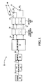
- FIG. 1 shows, in block diagram form, a transmitter in accordance with a single-user embodiment of the present invention
- FIGS. 2 , 3 and 4 show, in block diagram form, variants of a receiver in accordance with a single-user embodiment of the present invention
- FIG. 5 shows, in block diagram form, a transmitter in accordance with a multi-user embodiment of the present invention.
- FIG. 6 shows, in block diagram form, options for a receiver in accordance with a multi-user embodiment of the present invention.
- FIG. 1 shows a transmitter 20 in accordance with an embodiment of the present invention.
- the transmitter 20 receives information symbols 10 constituting a message from a digital data source 22 .
- the information symbols 10 are first passed through a forward error correction (FEC) encoder 24 , which is optional.
- FEC encoder 24 includes suitable circuitry, software and/or control logic for adding redundancy and/or memory to the information symbols 10 by encoding them into a sequence of coded symbols 12 .
- Suitable embodiments of the FEC encoder 24 include but are not limited to processing blocks implementing encoding operations such as block encoding (e.g., Reed-Solomon encoding), convolutional encoding, parallel or serial concatenated codes (turbo codes based on the concatenation of finite state machine (FSM) encoders) and so on.
- block encoding e.g., Reed-Solomon encoding
- convolutional encoding e.g., convolutional encoding
- parallel or serial concatenated codes turbo codes based on the concatenation of finite state machine (FSM) encoders
- the coded symbols 12 are fed to a mapper 26 , which includes suitable circuitry, software and/or control logic for translating the coded symbols 12 into a stream of modulation symbols 30 .
- the coded symbols 12 are bits and the modulation symbols are groups of log 2 M bits, where M is the number of possible modulation symbols.
- Each modulation symbol includes 1 ⁇ 2 log 2 M coded symbols mapped to a component in a first dimension (having ⁇ M possible values) and 1 ⁇ 2 log 2 M coded symbols mapped to a component in a second dimension (also having ⁇ M possible values).
- the resulting modulation symbol thus can be viewed as representing one of M points in a two-dimensional constellation.
- the stream of modulation symbols 30 is fed to a de-multiplexer 32 , which includes suitable circuitry, software and/or control logic for separating the modulation symbols 30 into a plurality of modulation symbol sub-streams 34 .
- the de-multiplexer 32 is connected to a channel interleaver 36 , which includes suitable circuitry, software and/or control logic for changing the order in which modulation symbols appear within each of the modulation symbol sub-streams 34 .
- the output of the channel interleaver 36 is therefore also a plurality of modulation symbol sub-streams 38 .
- the effect of the channel interleaver 36 is to increase the degree to which channel fading is independent between successive symbols in each of the modulation symbol sub-streams 38 .
- channel interleaver 36 is a buffer, which includes a two-dimensional array (i.e., a matrix) for each modulation symbol sub-stream 38 that is written to in a row-by-row manner and read from in a column-by-column manner.
- a two-dimensional array i.e., a matrix
- the modulation symbol sub-streams 38 produced by the channel interleaver 36 are fed to a respective plurality of transmit antennas 40 1 , 40 2 , . . . , 40 n T via a discrete-time (DT) to continuous-time (CT) unit 42 .
- the DT-to-CT unit 42 comprises suitable circuitry, software and/or control logic for applying a suitable modulation scheme to transform each modulation symbol in each of the modulation symbol sub-streams 38 into a continuous-time waveform.
- the output of the DT-to-CT unit 42 is a plurality of continuous-time waveforms 44 , which are then sent across a wireless channel 46 by the plurality of transmit antennas 40 1 , 40 2 , . . .
- the number of transmit antennas 40 1 , 40 2 , . . . , 40 n T (and the number of digital symbol sub-streams 38 ) is n T , where n T is an integer greater than or equal to two. This permits efficient reuse of the transmission spectrum.
- the transmit antennas 40 1 , 40 2 , . . . , 40 n T can be of any suitable type, including but not limited to omni-directional, sectorized, polarization, micro-array, adaptive, smart and so on.
- Suitable modulation schemes that can be used by the DT-to-CT unit 42 include, but are not limited to, binary phase-shift keying (BPSK), quadrature phase-shift keying (QPSK), pulse amplitude modulation (PAM), quadrature amplitude modulation (QAM) and spread spectrum modulation (used in code division multiple-access (CDMA) based systems).
- BPSK binary phase-shift keying
- QPSK quadrature phase-shift keying
- PAM pulse amplitude modulation
- QAM quadrature amplitude modulation
- CDMA code division multiple-access
- M-ary QAM each digital symbol consists of two components, one of which governs the amplitude of a given carrier signal, while the other governs the amplitude of a phase-shifted version of that carrier signal.
- b t [b t,1 ,b t,2 , . . . , b t,n T ] T , where T is the transpose operation.
- the modulation symbols in the transmit vector b t will have the same transmission period (i.e., the corresponding continuous-time waveform lasts the same amount of time), will be transmitted simultaneously by the transmit antennas 40 1 , 40 2 , . . . , 40 n T and will represent the same number of coded symbols.
- those skilled in the art will find it within their capabilities to modify these parameters in order to suit particular design requirements.
- the signals transmitted by the transmit antennas 40 1 , 40 2 , . . . , 40 n T suffer from co-antenna interference (CAI).
- CAI co-antenna interference
- the signals at each of n R receive antennas will be a superposition of the various transmitted signals.
- signals traveling across the wireless channel 46 are affected by quasi-static Rayleigh fading and additive white Gaussian noise, that there is no line of sight (LOS) between any of the transmit antennas and any of the receive antennas.
- LOS line of sight
- the amplitudes of the path gains are modeled as samples of a complex Gaussian random variable with a mean of zero and a variance of 0.5 in each dimension.
- the present invention will provide improvements regardless of whether the fading is Ricean, Rayleigh, etc., and, moreover, regardless of whether the fading is correlated or uncorrelated.
- AWGN additive white Gaussian noise
- H [ h 1 , 1 h 1 , 2 ⁇ h 1 , n T h 2 , 1 h 2 , 2 ⁇ h 2 , n T ⁇ ⁇ ⁇ ⁇ h n R , 1 h n R , 2 ⁇ h n R , n T ] , where coefficient h i,j is the path gain from the j-th transmit antenna to the i-th receive antenna, 1 ⁇ j ⁇ n T , 1 ⁇ i ⁇ n R .
- the receiver 60 includes a plurality of receive antennas 62 1 , 62 2 , . . . , 62 n R . It is envisaged that n R ⁇ n T . This is usually feasible in an uplink communication scenario because an abundance of antennas and processing power will usually be permitted at the receiver. However, it should be understood that the present invention is not restricted to the uplink communication scenario, nor is there a requirement that for a specific relationship between n T and n R . In general, all that is required is that n T and n R , the numbers of transmit and receive antennas, be greater than one. This is generally achievable in both upstream and downstream scenarios.
- the receive antennas 62 1 , 62 2 , . . . , 62 n R can be of any suitable type, including but not limited to omni-directional, sectorized, polarization, micro-array, adaptive, smart and so on.
- the output of each of the n R receive antennas 62 1 , 62 2 , . . . , 62 n R is a respective continuous-time waveform 64 1 , 64 2 , . . . , 64 n R , which is provided to a respective portion of a CT-to-DT unit 66 .
- the CT-to-DT unit 66 comprises suitable circuitry, software and/or control logic for discretizing each continuous-time waveform to produce a sequence of numerical values therefrom.
- the CT-to-DT unit 66 is operative to demodulate the continuous-time waveforms 64 1 , 64 2 , . . . , 64 n R using a demodulation scheme that is the opposite of the modulation scheme used by the DT-to-CT unit 42 .
- the CT-to-DT unit 66 is operable to determine the amplitude of a first component that appears to be modulating a predetermined carrier and the amplitude of a second component that appears to be modulating the 90-degree phase-shifted version of that carrier.
- both of these components are represented in a single complex number.
- the elements of r t can be real or complex values.
- the vector r t emerging from the DT-to-CT unit 66 is provided to a space matched filter 68 .
- the basic idea of the space matched filter 68 is to correlate (or match) the vector r t with a “vector of chip amplitudes” corresponding to each of the transmit antennas 40 1 , 40 2 , . . . , 40 n T .
- the “vector of chip amplitudes” corresponding to a given transmit antenna is indicative of a channel characteristic associated with that transmit antenna.
- the “vector of chip amplitudes” corresponding to a given transmit antenna is indicative of the degree to which the signal from that transmit antenna has been spread out amongst the receive antennas 62 1 , 62 2 , . . . , 62 n R .
- the “vector of chip amplitudes” corresponding to the j th transmit antenna is ideally the j th normalized column of the channel transfer matrix H, which is denoted s j .
- S is the matrix of “vectors of chip amplitudes”, i.e.:
- R [ 1 ... ⁇ 1 , n T ... ... ... ⁇ 1 , n T ... 1 ]
- Equation 1A shows that the space matched filter 68 executes a matrix multiplication operation on r t (the received vector), which is a Linear combination of the elements of r t , in order to obtain y t (the filtered vector).
- Equation 1B shows that the elements of y t are noisy and scaled observations of the elements of b t (the transmitted vector).
- the space matched filter 68 is assumed to have some knowledge of the channel characteristics, i.e., the columns of H. This is a reasonable assumption, as such characteristics could be measured or estimated directly by the receiver 60 based on observations of the channel 46 .
- the transmitter 20 may be provided with an estimator, which is capable of determining H either partially or completely; knowledge of the channel transfer matrix H could then be supplied to the space matched filter 68 .
- the channel transfer matrix H used in the computations correspond exactly to the actual channel transfer matrix.
- Advantageous performance can be achieved even if the estimates of the channel state information used by the space matched filter 68 deviate from the actual channel state information.
- a pre-selected value for the channel transfer matrix H could be used, based on previous measurements or estimates, or based on analytical computations or simplifications. If the elements of H, or the norms of the columns of H, are within, say 10% of their true values, then there will still be advantages to space matched filtering using H.
- the ⁇ ij are correlations between the normalized columns of H, i.e., the columns of S.
- the correlations ⁇ ij can be non-zero as the columns of H are not orthogonal.
- CAI co-antenna interference
- the elements of the vector y t at the output of the space matched filter 68 are fed to a detector 70 , which comprises suitable circuitry, software and/or control logic for computing probabilities on the transmitted symbols. That is to say, given the filtered vector y t at the output of the space matched filter 68 , the detector 70 is operative to compute the probability of each element of the transmit symbol vector b t being equal to a particular modulation symbol represented by real (or complex) components. This can be achieved using maximum likelihood or maximum a posteriori techniques based on the filtered vector y t and assumptions about the noise statistics through the channel.
- the detector 70 can estimate the mean and variance of the noise for each possible modulation symbol in the transmit symbol vector b t . Based on these estimates, the detector 70 computes, for the k th transmit antenna, a set of M probability values ⁇ 82 k ⁇ , where M denotes the number of possible modulation symbols.
- the information symbols 10 produced by the digital data source 22 are bits and that these bits are coded using a FEC encoder 24 to produce coded symbols 12 (which are also bits).
- BPSK binary phase shift keying
- M binary phase shift keying
- M mapping coded bit ‘0’ to modulation symbol ‘ ⁇ 1’
- coded bit ‘1’ to modulation symbol ‘1’.
- These modulation symbols are passed to the DT to CT unit 42 , which performs amplitude shift keying.
- the amplitude matrix A of the channel transfer matrix H for one instance of transmission be given by:
- the variance of the CAI noise for the first antenna is:
- the variance of the AWGN on the channel is 0.5
- the n T sets of M probability values each are then passed to a channel de-interleaver 72 , a multiplexer 74 and then a de-mapper of demodulator 76 .
- the channel de-interleaver 72 performs basically the inverse operations to those of the channel interleaver 36 . However, the channel de-interleaver 72 acts on n T streams of M probability values per stream rather than simply n T symbol sub-streams.
- the channel de-interleaver 72 comprises suitable circuitry, software and/or control logic for time-rearranging each received stream of sets of probability values ⁇ 82 1 ⁇ , ⁇ 82 2 ⁇ , . . . , ⁇ 82 n T ⁇ into a de-interleaved stream of sets of probability values ⁇ 84 1 ⁇ , ⁇ 84 2 ⁇ , . . . , ⁇ 84 n T ⁇ .
- the multiplexer 74 acts to reassemble the data into the order which existed at the output of the mapper 26 .
- the multiplexer 74 comprises circuitry, software and/or control logic for combining the de-interleaved sets of probability values ⁇ 84 1 ⁇ , ⁇ 84 2 ⁇ , ⁇ 84 n T ⁇ into a single stream of sets of probability values ⁇ 86 ⁇ .
- Each set of probability values in this stream is thus associated with a respective transmitted symbol, with the probability value occupying a particular position in the set representing the likelihood of that transmitted symbol acquiring a corresponding predetermined value.
- the de-mapper 76 serves to convert each set of M probability values received from the multiplexer 74 into a hard or soft decision about the transmitted coded symbol.
- the de-mapper 76 may comprise suitable circuitry, software and/or control logic for selecting, as the best transmitted coded symbol, the predetermined symbol corresponding to the position in the set ⁇ 86 ⁇ which is occupied by the greatest probability value.
- the de-mapper 76 may comprise suitable circuitry, software and/or control logic for creating a probability on each particular transmitted coded symbol by performing a weighted sum on the probabilities from the detector 70 . Each element of the sum is weighted by a 1 or 0 depending if the particular coded symbol is contained in the appropriate bit position of the modulation symbol.
- the probability of the 2i-th transmitted coded symbol being 0 is 1*P[modulation symbol for 00]+1*P[modulation symbol for 01]+0*P[modulation symbol for 10]+0*P[modulation symbol for 11].
- the probability of the (2i+1)-th transmitted coded symbol being 0 is 1*P[modulation symbol for 00]+0*P[modulation symbol for 01]+1*P[modulation symbol for 10]+0*P[modulation symbol for 11]
- the output of the de-mapper 76 is fed via link 90 to an FEC decoder 80 , which performs the inverse function of the FEC encoder 24 (if such FEC encoder 24 is used). It is noted that if the FEC decoder 80 is a soft-decision FEC decoder 80 , then it is possible to configure the FEC decoder 80 to generate reliability values on the transmitted coded symbols (also known as soft decisions or estimates of the coded symbols probabilities). Then, the de-mapper 76 can be changed to merge these (shown by link 88 in FIG. 2 ) with the probability values arriving from the multiplexer 74 . Otherwise the de-mapper 76 simply passes its soft output to the FEC decoder 80 (without iteration). The FEC decoder 80 then provides its output to a data sink 78 via a link 92 .
- the receiver 60 ′ is equipped with iterative processing between the FEC decoder 80 and a modified detector 70 ′. Specifically, after computing the reliability values on the transmitted coded symbols, the decoder 80 can then reassemble these into reliability values on the transmitted modulation symbols (also known as soft decisions or estimates of probabilities of the modulation symbols). The reliability values (shown by link 94 in FIG. 3 ) are provided to the detector 70 ′.
- the mean and variance of the CAI noise source may then be re-computed by the detector 70 ′ (using (Equation 3A) and (Equation 3B) above, with different values for the P[Q jk ]), which will tend to more accurately reflect the actual mean and variance of the CAI.
- an interference reducing filter can be applied to the output of the space matched filter 68 .
- a suitable interference reducing filter is a minimum mean square error (MMSE) filter, although other conventional examples of interference reducing filters (e.g., interference reducing filters used in speech systems) are suitable and will be known to those skilled in the art.
- FIG. 4 illustrates a block diagram of a receiver 60 ′′ equipped with this optional functionality.
- the detector 70 has the same structure as that described in FIG. 2 , however it operates on the output of an interference reducing filter 71 .
- the output of the interference reducing filter 71 is thus given by:
- One can write the output of the interference reducing filter 71 for the first transmit antenna as: z 1,t C 11 b 1,t +C 12 b 2,t + . . . +C 1n T b n T ,t +w 1,t , (Equation 4) where the desired signal is C 11 b 1,t , the last n T, ⁇ 1 terms are due to (reduced) CAI
- Equation 4 is very similar in form to (Equation 2). Hence, it is possible to calculate the mean and variance in a similar fashion as before. Then the detector 70 can compute the probability values on the transmitted symbols and pass these on to the channel de-interleaver 72 , multiplexer 74 , de-mapper 76 and subsequently to the FEC decoder 80 as has already been described.
- the techniques described herein find utilization in the presence of ISI induced by a frequency-selective fading channel.
- One example of such utilization involves the use of an ISI reducing equalization filter at the front end of the receiver, in which case the residual ISI contributions will be ignored by the detector 70 and treated as an additional source of noise.
- Another example of such utilization involves the use of a RAKE receiver to collect all the energy of the power delay profile of the signal at the front end of the receiver, in which case one would again proceed as previously described, utilizing the detector 70 and (possibly iterative) post processing after the RAKE receiver pre-processing.
- the present invention is also applicable in case of multiple users sharing the same communication channel, e.g., for uplink transmission from the mobile to the base station.
- the receiver described in FIGS. 2 , 3 and 4 can be applied directly to the case of TDMA, FDMA and orthogonal CDMA based multi-user communication systems, as the users can be separated due to their presence in different time/frequency/code dimension (i.e., the users are orthogonal).
- the following considerations apply for non-orthogonal CDMA systems that employ multiple antenna technology.
- FIG. 5 illustrates a schematic block diagram of a transmission scenario for K users on a CDMA network.
- Each user has a conventional single user transmitter 20 1 , . . . , 20 K with single or multiple antennas, depending on the type of mobile unit (e.g., laptop, cellular phone, PDA, etc.)
- each of the transmitters 20 1 , . . . , 20 K comprises a respective one of K digital data sources 22 1 , . . . , 22 K , resulting in the production of K streams of information symbols that pass through respective optional FEC encoders 24 1 , . . . , 24 K .
- the FEC encoders 24 1 , . . . , 24 K include suitable circuitry, software and/or control logic for adding redundancy and/or memory to each stream of information symbols by encoding them into a respective sequence of coded symbols.
- the K streams of coded symbols are fed to a respective plurality of mappers 26 1 , . . . , 26 K , each of which includes suitable circuitry, software and/or control logic for translating the coded symbols in the respective stream of coded symbols into a respective stream of modulation symbols.
- each mapper includes a respective user's spreading CDMA sequence.
- Each stream of modulation symbols is fed to a respective one a plurality of de-multiplexers 32 1 , . . . , 32 K , each of which includes suitable circuitry, software and/or control logic for separating the respective stream of modulation symbols into a respective plurality of modulation symbol sub-streams.
- each channel interleaver 36 1 , . . . , 36 K is connected to a respective channel interleaver 36 1 , . . . , 36 K , which includes suitable circuitry, software and/or control logic for changing the order in which modulation symbols appear within each of the respective modulation symbol sub-streams.
- the output of each channel interleaver 36 1 , . . . , 36 K is therefore a respective plurality of modulation symbol sub-streams.
- the set of modulation symbol sub-streams produced by each of the channel interleavers 36 1 , . . . , 36 K are fed to a respective plurality of transmit antennas via a respective DT-to-CT unit (not shown).
- the DT-to-CT unit modulates each modulation signal sub-stream in accordance with a CDMA chip sequence for that symbol.
- the continuous-time waveforms for the modulation symbol sub-streams produced by channel interleaver 36 1 are fed to a transmit antennas 40 1 1 , 40 1 2 , . . .
- FIG. 6 illustrates the schematic block diagram of a receiver 60 * (e.g., at the base station) having a multi-user detector/decoder. It is assumed that the scenario of FIG. 5 applies, i.e., there are K distinct users transmitting their data to the base station over the same communication channel, while utilizing n k T transmit antennas respectively.
- the receiver 60 * includes n R receive antennas.
- n R will be greater than one.
- the output of each of the n R receive antennas is a respective continuous-time waveform, which is provided to a respective portion of a CT-to-DT unit 66 *.
- the CT-to-DT unit 66 comprises suitable circuitry, software and/or control logic for discretizing each continuous-time waveform to produce a sequence of numerical values therefrom.
- the CT-to-DT unit 66 * is operative to demodulate the continuous-time waveforms 64 1 , 64 2 , . . . , 64 n R using a demodulation scheme that is based on CDMA chips, i.e., it operates at the chip rate of the DT-to-CT unit in the transmitter (not shown in FIG. 5 ).
- the received signal (after the CT-to-DT unit 66 *) can be represented as follows, assuming that the conversion has been done on the CDMA chip level:
- the CT-to-DT unit 66 * is followed by a space matched filter 68 *.
- the space matched filter 68 * can be implemented as a bank of CDMA matched filters or a suitable CDMA multi-user detector.
- the basic idea of the space matched filter 68 * is, for each k th user, to correlate (or match) the received vector with a “vector of chip amplitudes” corresponding to each of that user's transmit antennas 40 k 1 , 40 k 2 , . . . , 40 k n k T .
- the “vector of chip amplitudes” corresponding to a given transmit antenna of a given user is indicative of a channel characteristic associated with that transmit antenna.
- the “vector of chip amplitudes” corresponding to a given transmit antenna of a given user is indicative of the degree to which the signal from that transmit antenna of that user has been spread out amongst the n R receive antennas.
- the “vector of chip amplitudes” corresponding to the j th transmit antenna of the k th user is ideally the j th normalized column of the k th channel transfer sub-matrix H k .
- Equation 5 Equation 5 for the amplitude matrix A k of sub-matrix H k , where H denotes the Hermitian operator and R k is defined by:
- R k _ [ 1 ⁇ ⁇ 1 , n T k k ⁇ ⁇ ⁇ ⁇ 1 , n T k k ⁇ 1 ]
- ⁇ k i,j ⁇ s k i ,s k j >,
- the output of the space matched filter 68 * leads to a soft decision detector 70 * and, optionally, an interference reducing filter 71 *.
- the data are treated in parallel (i.e., separately) by a bank of de-interleavers 72 1 , . . . , 72 K , followed by a bank of multiplexers 74 1 , . . . , 74 K and, if used, a bank of FEC decoders 80 1 , . . . , 80 K for users 1, 2, . . . , K.
- each decoder 80 1 , 80 2 , . . . , 80 K is fed to a respective data sink 78 1 , 78 2 , . . . , 78 K , one for each of the K users.
- each of the de-mappers 76 1 , . . . , 76 K can be designed to merge these reliability values with the probability values arriving from the respective multiplexer 74 1 , . . . , 74 K as.
- the receiver 60 * is equipped with iterative processing. After computing the reliability values on the transmitted coded symbols, the PEC decoders 80 1 , . . . , 80 K can then reassemble these reliability values into reliability values on the transmitted modulation symbols. These reliability values (also known as soft decisions or probability estimates of the transmitted modulation symbols) are provided to the detector 70 * via respective links 94 1 , . . . , 94 K .
- the mean and variance of the CAI noise source may then be re-computed by the detector 70 * (using equations analogous to (equation 3A) and (Equation 3B), above, with different values for the P[Q jk ]), which will tend to more accurately reflect the actual mean and variance of the CAI.
- the present invention need not be restricted to use in wireless systems.
- the present invention can also be useful to solve detection problems in those situations where the channel over which data is transmitted can be modeled by way of a channel transfer matrix of the type described herein above.
- other examples of such areas of application include, but are not limited to (i) wireline data transmission when data are affected by channel cross-talk; (ii) data readout from CD/DVD/other optical recording medium when multiple lasers and detectors are used concurrently; (iii) data read-out from a magnetic disk or magnetic tape when multiple read-heads are used; and (iv) deep sea data communications.
- the channel transfer matrix can describe the effect of transmission over such a channel and the effects can be exploited to advantage through the use of a space matched filter.
Landscapes
- Engineering & Computer Science (AREA)
- Computer Networks & Wireless Communication (AREA)
- Signal Processing (AREA)
- Physics & Mathematics (AREA)
- Mathematical Physics (AREA)
- Radio Transmission System (AREA)
Abstract
Description
r t =Hb t +v t,
where H denotes a channel transfer matrix used to describe the effect of fading and multi-antenna interference on the multi-input, multi-output (MIMO)
where coefficient hi,j is the path gain from the j-th transmit antenna to the i-th receive antenna, 1≦j≦nT, 1≦i≦nR.
and
-
- A is an amplitude matrix, i.e.:
yt =S Hrt. (Equation 1A)
r t =SAb t +v t.
where H denotes the Hermitian operator and R is defined by:
where
ρi,j =<s i ,s j>, ρij=ρ*i,j, and
with the inner product operation <si, sj> signifying
y i,t =A 1 b 1,t +A 2ρ12 b 2,t + . . . +A n
are due to CAI. Hence, one may consider the transmitted symbol corrupted by two sources of noise, the Gaussian noise term (n1,t) and the CAI. The more transmitting antennas there are, the more accurately one may approximate this combined interference for each receive antenna as being Gaussian distributed with a mean and a variance that is function of the ρij, i.e., the correlation between the columns of H. In an embodiment, a separate processing unit can be provided which would comprise suitable circuitry, software and/or control logic to estimate this mean and variance.
and the correlation matrix R be given by:
M y=(R+σ AWGN 2 A −2)−1.
which can be written as:
z t =Cb t +w t,
where C=MyRA. One can write the output of the
z 1,t =C 11 b 1,t +C 12 b 2,t + . . . +C 1n
where the desired signal is C11b1,t, the last nT,−1 terms are due to (reduced) CAI
and wt is assumed to be a Gaussian noise source. Clearly, (Equation 4) is very similar in form to (Equation 2). Hence, it is possible to calculate the mean and variance in a similar fashion as before. Then the
where
-
- sub-matrix Hk is an nR×nk T matrix reflecting the channel attenuation factors between the nk T antennas of the kth user and the nR receive antennas of the base station,
- the spreading sequence of length N, utilized by the kth user at the kth user's j-th transmit antenna is represented by a column vector wj k of size N×1,
- the data symbols transmitted by the kth user are given by a vector bk of size nk T×1.
y k =R k A k b k +n k (Equation 5)
for the amplitude matrix Ak of sub-matrix Hk, where H denotes the Hermitian operator and Rk is defined by:
where
ρk i,j=<sk i,sk j>, ρk i,j=ρk*j,i
with sk i being the ith column of sub-matrix Hk and with the inner product operation <sk i, sk j> signifying Σm=1 to n
Claims (25)
Priority Applications (1)
| Application Number | Priority Date | Filing Date | Title |
|---|---|---|---|
| US10/544,108 US7672401B2 (en) | 2003-02-03 | 2004-02-02 | System and method for data communication over multi-input, multi-output channels |
Applications Claiming Priority (3)
| Application Number | Priority Date | Filing Date | Title |
|---|---|---|---|
| US44417903P | 2003-02-03 | 2003-02-03 | |
| US10/544,108 US7672401B2 (en) | 2003-02-03 | 2004-02-02 | System and method for data communication over multi-input, multi-output channels |
| PCT/CA2004/000137 WO2004071001A1 (en) | 2003-02-03 | 2004-02-02 | System and method for data communication over multi-input, multi-output channels |
Publications (2)
| Publication Number | Publication Date |
|---|---|
| US20060135081A1 US20060135081A1 (en) | 2006-06-22 |
| US7672401B2 true US7672401B2 (en) | 2010-03-02 |
Family
ID=32850830
Family Applications (1)
| Application Number | Title | Priority Date | Filing Date |
|---|---|---|---|
| US10/544,108 Expired - Fee Related US7672401B2 (en) | 2003-02-03 | 2004-02-02 | System and method for data communication over multi-input, multi-output channels |
Country Status (2)
| Country | Link |
|---|---|
| US (1) | US7672401B2 (en) |
| WO (1) | WO2004071001A1 (en) |
Cited By (4)
| Publication number | Priority date | Publication date | Assignee | Title |
|---|---|---|---|---|
| US20090285193A1 (en) * | 2008-02-28 | 2009-11-19 | Lg Electronics Inc. | Method for multiplexing data and control information |
| US20130003760A1 (en) * | 2009-03-27 | 2013-01-03 | Sony Corporation | Division of bit streams to produce spatial paths for multicarrier transmission |
| US20150110216A1 (en) * | 2012-04-27 | 2015-04-23 | The Royal Institution For The Advancement Of Learning/Mcgill University | Methods and devices for communications systems using multiplied rate transmission |
| US20150372745A1 (en) * | 2013-02-08 | 2015-12-24 | Pioneer Corporation | Diversity reception apparatus, diversity reception method, reception program, and recording medium |
Families Citing this family (21)
| Publication number | Priority date | Publication date | Assignee | Title |
|---|---|---|---|---|
| WO2004071001A1 (en) | 2003-02-03 | 2004-08-19 | Mcgill University | System and method for data communication over multi-input, multi-output channels |
| EP1511211B1 (en) * | 2003-08-29 | 2008-04-09 | Mitsubishi Electric Information Technology Centre Europe B.V. | Method for transmitting data in a MIMO telecommunication system offering a high diversity as perceived from a receiver end |
| US7440510B2 (en) * | 2003-09-15 | 2008-10-21 | Intel Corporation | Multicarrier transmitter, multicarrier receiver, and methods for communicating multiple spatial signal streams |
| US7649833B2 (en) | 2003-12-29 | 2010-01-19 | Intel Corporation | Multichannel orthogonal frequency division multiplexed receivers with antenna selection and maximum-ratio combining and associated methods |
| US7440423B2 (en) * | 2004-01-12 | 2008-10-21 | Intel Corporation | Channel specification apparatus, systems, and methods |
| US20050152330A1 (en) * | 2004-01-12 | 2005-07-14 | Stephens Adrian P. | Clock recovery methods and apparatus |
| JP4099592B2 (en) * | 2004-06-10 | 2008-06-11 | ソニー株式会社 | COMMUNICATION SYSTEM, TRANSMISSION DEVICE, AND RECEPTION DEVICE |
| US7398066B2 (en) * | 2004-11-30 | 2008-07-08 | Stmicroelectronics, Inc. | Communication system control using reliability data |
| US7434146B1 (en) * | 2005-05-06 | 2008-10-07 | Helwett-Packard Development Company, L.P. | Denoising and error correction for finite input, general output channel |
| US20070019756A1 (en) * | 2005-07-25 | 2007-01-25 | Navini Networks, Inc. | Low complexity soft detection in multiple transmit and receive antenna systems with M-QAM modulations |
| EP1775849A1 (en) | 2005-10-14 | 2007-04-18 | Telefonaktiebolaget LM Ericsson (publ) | Method and arrangement for interference mitigation |
| US8483240B2 (en) * | 2006-12-19 | 2013-07-09 | Lockheed Martin Corporation | Piggyback networks |
| US7885289B2 (en) * | 2006-12-19 | 2011-02-08 | Lockheed Martin Corporation | System and method for relaying turbo-coded piggyback messages |
| WO2008137837A1 (en) * | 2007-05-04 | 2008-11-13 | Amicus Wireless Technology Ltd. | Automatic gain control circuit for mimo ofdm receiver |
| US20090103568A1 (en) * | 2007-10-19 | 2009-04-23 | Mcgill University | Method and System for Non-Gaussian Code-Division-Multiple-Access Signal Transmission and Reception |
| EP2228935A1 (en) | 2009-03-13 | 2010-09-15 | Nederlandse Organisatie voor toegepast -natuurwetenschappelijk onderzoek TNO | MIMO communication method and devices |
| WO2011065746A2 (en) * | 2009-11-24 | 2011-06-03 | 한국전자통신연구원 | Method for recovering a frame that failed to be transmitted in a mu-mimo based wireless communication system |
| US8761608B2 (en) * | 2010-10-11 | 2014-06-24 | Nec Laboratories America, Inc. | Coded multidimensional pulse amplitude modulation for ultra-high-speed optical transport |
| US8873954B2 (en) * | 2012-02-01 | 2014-10-28 | Ramot At Tel-Aviv University Ltd. | System and method for exchanging information over a jacobi MIMO channel |
| WO2014143792A2 (en) | 2013-03-15 | 2014-09-18 | Orbital Sciences Corporation | Protection of commercial communications |
| CN104333434B (en) * | 2014-08-31 | 2017-09-22 | 电子科技大学 | A kind of spatial modulation detection method of low complex degree |
Citations (13)
| Publication number | Priority date | Publication date | Assignee | Title |
|---|---|---|---|---|
| US5852630A (en) * | 1997-07-17 | 1998-12-22 | Globespan Semiconductor, Inc. | Method and apparatus for a RADSL transceiver warm start activation procedure with precoding |
| EP0998045A1 (en) | 1998-10-30 | 2000-05-03 | Lucent Technologies Inc. | Digital transmission system and method |
| US6081566A (en) | 1994-08-02 | 2000-06-27 | Ericsson, Inc. | Method and apparatus for interference rejection with different beams, polarizations, and phase references |
| US6173014B1 (en) | 1994-08-02 | 2001-01-09 | Telefonaktiebolaget Lm Ericsson | Method of and apparatus for interference rejection combining and downlink beamforming in a cellular radio communications system |
| EP1213853A1 (en) | 2000-07-21 | 2002-06-12 | Mitsubishi Denki Kabushiki Kaisha | Receiver for wireless communication |
| EP1265377A2 (en) | 2001-06-06 | 2002-12-11 | Nec Corporation | Adaptive antenna reception apparatus |
| US6745050B1 (en) * | 2000-10-23 | 2004-06-01 | Massachusetts Institute Of Technology | Multichannel multiuser detection |
| US6757322B2 (en) * | 1998-11-24 | 2004-06-29 | Linex Technologies, Inc. | Space diversity and coding, spread-spectrum antenna and method |
| WO2004071001A1 (en) | 2003-02-03 | 2004-08-19 | Mcgill University | System and method for data communication over multi-input, multi-output channels |
| US7133459B2 (en) * | 2001-05-01 | 2006-11-07 | Texas Instruments Incorporated | Space-time transmit diversity |
| US7236536B2 (en) * | 2001-07-26 | 2007-06-26 | Lucent Technologies Inc. | Method and apparatus for detection and decoding of signals received from a linear propagation channel |
| US7359313B2 (en) * | 2002-06-24 | 2008-04-15 | Agere Systems Inc. | Space-time bit-interleaved coded modulation for wideband transmission |
| US7397826B2 (en) * | 2001-06-21 | 2008-07-08 | Koninklijke Philips Electronics N.V. | MIMO transmission system in a radio communications network |
-
2004
- 2004-02-02 WO PCT/CA2004/000137 patent/WO2004071001A1/en active Application Filing
- 2004-02-02 US US10/544,108 patent/US7672401B2/en not_active Expired - Fee Related
Patent Citations (13)
| Publication number | Priority date | Publication date | Assignee | Title |
|---|---|---|---|---|
| US6081566A (en) | 1994-08-02 | 2000-06-27 | Ericsson, Inc. | Method and apparatus for interference rejection with different beams, polarizations, and phase references |
| US6173014B1 (en) | 1994-08-02 | 2001-01-09 | Telefonaktiebolaget Lm Ericsson | Method of and apparatus for interference rejection combining and downlink beamforming in a cellular radio communications system |
| US5852630A (en) * | 1997-07-17 | 1998-12-22 | Globespan Semiconductor, Inc. | Method and apparatus for a RADSL transceiver warm start activation procedure with precoding |
| EP0998045A1 (en) | 1998-10-30 | 2000-05-03 | Lucent Technologies Inc. | Digital transmission system and method |
| US6757322B2 (en) * | 1998-11-24 | 2004-06-29 | Linex Technologies, Inc. | Space diversity and coding, spread-spectrum antenna and method |
| EP1213853A1 (en) | 2000-07-21 | 2002-06-12 | Mitsubishi Denki Kabushiki Kaisha | Receiver for wireless communication |
| US6745050B1 (en) * | 2000-10-23 | 2004-06-01 | Massachusetts Institute Of Technology | Multichannel multiuser detection |
| US7133459B2 (en) * | 2001-05-01 | 2006-11-07 | Texas Instruments Incorporated | Space-time transmit diversity |
| EP1265377A2 (en) | 2001-06-06 | 2002-12-11 | Nec Corporation | Adaptive antenna reception apparatus |
| US7397826B2 (en) * | 2001-06-21 | 2008-07-08 | Koninklijke Philips Electronics N.V. | MIMO transmission system in a radio communications network |
| US7236536B2 (en) * | 2001-07-26 | 2007-06-26 | Lucent Technologies Inc. | Method and apparatus for detection and decoding of signals received from a linear propagation channel |
| US7359313B2 (en) * | 2002-06-24 | 2008-04-15 | Agere Systems Inc. | Space-time bit-interleaved coded modulation for wideband transmission |
| WO2004071001A1 (en) | 2003-02-03 | 2004-08-19 | Mcgill University | System and method for data communication over multi-input, multi-output channels |
Non-Patent Citations (4)
| Title |
|---|
| Chip Fleming, A Tutorial on Convolutional Coding with Viterbi Decoding, copyright © 1999-2002, 6 pages, Spectrum Applications. |
| Description of the Algorithms (Part 1), copyright © 1999-2002, 7 pages, Spectrum Applications. |
| Matthew Valenti and Brian D. Woerner, Iterative Multiuser Detection for Convolutionally Coded Asynchronous DS-CDMA, 9th IEEE International Symposium . . . , Sep. 9, 1998, 21 pages. |
| Telecommunications and Mission Operations Directorate-DNS Technology Program, Communications Systems Analysis: Turbo Codes, 1 page, Oct. 23, 2002. |
Cited By (17)
| Publication number | Priority date | Publication date | Assignee | Title |
|---|---|---|---|---|
| US8891354B2 (en) | 2008-02-28 | 2014-11-18 | Lg Electronics Inc. | Method for multiplexing data and control information |
| US8094639B2 (en) * | 2008-02-28 | 2012-01-10 | Lg Electronics Inc. | Method for multiplexing data and control information |
| US8400978B2 (en) | 2008-02-28 | 2013-03-19 | Lg Electronics Inc. | Method for multiplexing data and control information |
| US8547923B2 (en) | 2008-02-28 | 2013-10-01 | Lg Electronics Inc. | Method for multiplexing data and control information |
| US20090285193A1 (en) * | 2008-02-28 | 2009-11-19 | Lg Electronics Inc. | Method for multiplexing data and control information |
| US10159064B2 (en) | 2008-02-28 | 2018-12-18 | Lg Electronics Inc. | Method for multiplexing data and control information |
| US9775136B2 (en) | 2008-02-28 | 2017-09-26 | Lg Electronics Inc. | Method for multiplexing data and control information |
| US20130003760A1 (en) * | 2009-03-27 | 2013-01-03 | Sony Corporation | Division of bit streams to produce spatial paths for multicarrier transmission |
| US8885686B2 (en) * | 2009-03-27 | 2014-11-11 | Sony Corporation | Division of bit streams to produce spatial paths for multicarrier transmission |
| US9531511B2 (en) * | 2009-03-27 | 2016-12-27 | Sony Corporation | Division of bit streams to produce spatial paths for multicarrier transmission |
| US20140369432A1 (en) * | 2009-03-27 | 2014-12-18 | Sony Corporation | Division of bit streams to produce spatial paths for multicarrier transmission |
| US9197382B2 (en) * | 2009-03-27 | 2015-11-24 | Sony Corporation | Division of bit streams to produce spatial paths for multicarrier transmission |
| US20160028515A1 (en) * | 2009-03-27 | 2016-01-28 | Sony Corporation | Division of bit streams to produce spatial paths for multicarrier transmission |
| US20150110216A1 (en) * | 2012-04-27 | 2015-04-23 | The Royal Institution For The Advancement Of Learning/Mcgill University | Methods and devices for communications systems using multiplied rate transmission |
| US9473332B2 (en) * | 2012-04-27 | 2016-10-18 | The Royal Institution For The Advancement Of Learning / Mcgill University | Methods and devices for communications systems using multiplied rate transmission |
| US9413449B2 (en) * | 2013-02-08 | 2016-08-09 | Pioneer Corporation | Diversity reception apparatus, diversity reception method, reception program, and recording medium |
| US20150372745A1 (en) * | 2013-02-08 | 2015-12-24 | Pioneer Corporation | Diversity reception apparatus, diversity reception method, reception program, and recording medium |
Also Published As
| Publication number | Publication date |
|---|---|
| US20060135081A1 (en) | 2006-06-22 |
| WO2004071001A1 (en) | 2004-08-19 |
Similar Documents
| Publication | Publication Date | Title |
|---|---|---|
| US7672401B2 (en) | System and method for data communication over multi-input, multi-output channels | |
| CA2472243C (en) | High rate transmission diversity transmission and reception | |
| US7573805B2 (en) | Data transmission and reception method and apparatus | |
| US6891897B1 (en) | Space-time coding and channel estimation scheme, arrangement and method | |
| US7881360B2 (en) | Method and system for increased bandwidth efficiency in multiple input—multiple output channels | |
| US7929631B2 (en) | Multiple space time transmit diversity communication system with selected complex conjugate inputs | |
| US6934320B2 (en) | Orthogonalized spatial multiplexing for wireless communication | |
| US7672384B2 (en) | Bandwidth and power efficient multicarrier multiple access | |
| US20030112745A1 (en) | Method and system of operating a coded OFDM communication system | |
| CN1930813B (en) | Receiver apparatus, receiving method, and wireless communication system | |
| Tujkovic | Space-time turbo coded modulation for wireless communication systems | |
| Claussen et al. | High-performance MIMO receivers based on multi-stage partial parallel interference cancellation | |
| Roopa et al. | Performance Improvement Of MIMO System Using OSTBC Scheme and ML Detection Technique Under Rayleigh Channel | |
| Kawamoto et al. | Independent turbo coding and common interleaving method among transmitter branches achieving peak throughput of 1 Gbps in OFCDM MIMO multiplexing | |
| Remlein | FDMA System with Space–Time Encoded CPM Signals | |
| Vishvaksenan et al. | Performance of turbo coded Space-Time transmit diversity aided IDMA system | |
| Dohler et al. | Implementable wireless access for B3G networks. III. Complexity reducing transceiver structures [Topics in Radio Communications] | |
| Lampinen et al. | HSDPA Mimo Performance with Turbo Equalizer | |
| Ro et al. | Adaptive modulation and coding of MIMO in next generation mobile systems | |
| Missaoui | Active users’ identification and collision resolution in multi-user MIMO systems | |
| Zhang et al. | A new scheme of space division multiplexing and its analysis | |
| Rivera et al. | Space-time iterative multiuser receiver for a coded DS-CDMA system in a flat fading channel | |
| Zhang et al. | Performance Research and Simulation on Space-Time Block Code in Frequency-Selective Fading Channels | |
| Thomas | Efficient algorithms for broadband space-time-coded wireless communication | |
| Chi | The Impact of Channel Estimation Error on Space-Time Block and Trellis Codes in Flat and Frequency Selective Channels |
Legal Events
| Date | Code | Title | Description |
|---|---|---|---|
| AS | Assignment |
Owner name: MCGILL UNIVERSITY,CANADA Free format text: ASSIGNMENT OF ASSIGNORS INTEREST;ASSIGNORS:MYSORE, NAVEEN;BAJCSY, JAN;REEL/FRAME:017653/0044 Effective date: 20060209 Owner name: MCGILL UNIVERSITY, CANADA Free format text: ASSIGNMENT OF ASSIGNORS INTEREST;ASSIGNORS:MYSORE, NAVEEN;BAJCSY, JAN;REEL/FRAME:017653/0044 Effective date: 20060209 |
|
| STCF | Information on status: patent grant |
Free format text: PATENTED CASE |
|
| FPAY | Fee payment |
Year of fee payment: 4 |
|
| FEPP | Fee payment procedure |
Free format text: MAINTENANCE FEE REMINDER MAILED (ORIGINAL EVENT CODE: REM.) |
|
| FEPP | Fee payment procedure |
Free format text: 7.5 YR SURCHARGE - LATE PMT W/IN 6 MO, SMALL ENTITY (ORIGINAL EVENT CODE: M2555) |
|
| MAFP | Maintenance fee payment |
Free format text: PAYMENT OF MAINTENANCE FEE, 8TH YR, SMALL ENTITY (ORIGINAL EVENT CODE: M2552) Year of fee payment: 8 |
|
| FEPP | Fee payment procedure |
Free format text: MAINTENANCE FEE REMINDER MAILED (ORIGINAL EVENT CODE: REM.); ENTITY STATUS OF PATENT OWNER: SMALL ENTITY |
|
| LAPS | Lapse for failure to pay maintenance fees |
Free format text: PATENT EXPIRED FOR FAILURE TO PAY MAINTENANCE FEES (ORIGINAL EVENT CODE: EXP.); ENTITY STATUS OF PATENT OWNER: SMALL ENTITY |
|
| STCH | Information on status: patent discontinuation |
Free format text: PATENT EXPIRED DUE TO NONPAYMENT OF MAINTENANCE FEES UNDER 37 CFR 1.362 |
|
| FP | Lapsed due to failure to pay maintenance fee |
Effective date: 20220302 |