US7624314B1 - Echo canceler-based mechanism for performing and reporting fault diagnostic testing of repeatered telecommunication line - Google Patents
Echo canceler-based mechanism for performing and reporting fault diagnostic testing of repeatered telecommunication line Download PDFInfo
- Publication number
- US7624314B1 US7624314B1 US11/612,667 US61266706A US7624314B1 US 7624314 B1 US7624314 B1 US 7624314B1 US 61266706 A US61266706 A US 61266706A US 7624314 B1 US7624314 B1 US 7624314B1
- Authority
- US
- United States
- Prior art keywords
- fault
- repeater
- wireline
- repeatered
- central office
- Prior art date
- Legal status (The legal status is an assumption and is not a legal conclusion. Google has not performed a legal analysis and makes no representation as to the accuracy of the status listed.)
- Expired - Lifetime, expires
Links
- 230000007246 mechanism Effects 0.000 title abstract description 8
- 238000002405 diagnostic procedure Methods 0.000 title description 2
- 230000004044 response Effects 0.000 claims abstract description 49
- 238000005259 measurement Methods 0.000 claims abstract description 15
- 238000000034 method Methods 0.000 claims description 26
- 238000012545 processing Methods 0.000 claims description 22
- 230000008569 process Effects 0.000 claims description 5
- 238000012360 testing method Methods 0.000 description 15
- 238000004422 calculation algorithm Methods 0.000 description 14
- 238000001514 detection method Methods 0.000 description 11
- 238000010586 diagram Methods 0.000 description 11
- 239000004020 conductor Substances 0.000 description 9
- 230000006870 function Effects 0.000 description 8
- 238000004891 communication Methods 0.000 description 6
- 238000011144 upstream manufacturing Methods 0.000 description 6
- 238000012423 maintenance Methods 0.000 description 5
- 238000010168 coupling process Methods 0.000 description 3
- 238000005859 coupling reaction Methods 0.000 description 3
- 238000003745 diagnosis Methods 0.000 description 3
- 230000010354 integration Effects 0.000 description 3
- 238000012549 training Methods 0.000 description 3
- 230000003044 adaptive effect Effects 0.000 description 2
- 230000008901 benefit Effects 0.000 description 2
- 230000008878 coupling Effects 0.000 description 2
- 238000003780 insertion Methods 0.000 description 2
- 230000037431 insertion Effects 0.000 description 2
- 238000013178 mathematical model Methods 0.000 description 2
- 238000012986 modification Methods 0.000 description 2
- 230000004048 modification Effects 0.000 description 2
- 230000000644 propagated effect Effects 0.000 description 2
- 238000004088 simulation Methods 0.000 description 2
- 230000007704 transition Effects 0.000 description 2
- RYGMFSIKBFXOCR-UHFFFAOYSA-N Copper Chemical compound [Cu] RYGMFSIKBFXOCR-UHFFFAOYSA-N 0.000 description 1
- 230000006978 adaptation Effects 0.000 description 1
- 230000000903 blocking effect Effects 0.000 description 1
- 238000004364 calculation method Methods 0.000 description 1
- 239000003990 capacitor Substances 0.000 description 1
- 230000008859 change Effects 0.000 description 1
- 230000001684 chronic effect Effects 0.000 description 1
- 229910052802 copper Inorganic materials 0.000 description 1
- 239000010949 copper Substances 0.000 description 1
- 230000002596 correlated effect Effects 0.000 description 1
- 230000007423 decrease Effects 0.000 description 1
- 230000004069 differentiation Effects 0.000 description 1
- 230000000694 effects Effects 0.000 description 1
- 238000005516 engineering process Methods 0.000 description 1
- 238000010348 incorporation Methods 0.000 description 1
- 238000009434 installation Methods 0.000 description 1
- 230000003993 interaction Effects 0.000 description 1
- 238000002955 isolation Methods 0.000 description 1
- 238000000691 measurement method Methods 0.000 description 1
- 238000012544 monitoring process Methods 0.000 description 1
- 238000007430 reference method Methods 0.000 description 1
- 238000005316 response function Methods 0.000 description 1
- 238000005070 sampling Methods 0.000 description 1
- 238000000926 separation method Methods 0.000 description 1
- 230000011664 signaling Effects 0.000 description 1
- 230000003595 spectral effect Effects 0.000 description 1
- 238000012546 transfer Methods 0.000 description 1
- 230000001960 triggered effect Effects 0.000 description 1
Images


Classifications
-
- H—ELECTRICITY
- H04—ELECTRIC COMMUNICATION TECHNIQUE
- H04M—TELEPHONIC COMMUNICATION
- H04M3/00—Automatic or semi-automatic exchanges
- H04M3/08—Indicating faults in circuits or apparatus
- H04M3/085—Fault locating arrangements
Definitions
- the present invention relates in general to communication systems, and is particularly directed to a digital echo canceler-based technique for conducting, and reporting via an overhead channel, parametric measurements on successive segments of a repeatered wireline, and determining from measured echo canceler tap data the location of a fault along a respective segment of the wireline.
- a common maintenance issue involves resolving a service-impairing fault that has occurred somewhere along a DSL circuit.
- craftspersons or service technicians may be dispatched to one or more locations along the DSL circuit.
- CO central office
- SSI&M technician has the responsibility of resolving a problem at the customer premises.
- the invention disclosed in the above referenced applications, to be described hereinbelow with reference to FIGS. 1-19 successfully addresses these shortcomings, by making use of the digital echo canceler that is resident in the transceiver of an industry standard DSL line card, to estimate changes in echo path, both upstream and downstream of an apparent line fault. Locating the peak of the return signal allows the echo channel information to be correlated directly to the location of the fault.
- FIG. 1 A reduced complexity diagram of a DSL line card transceiver employing a PAM/QAM based digital echo canceler used for this purpose is shown in FIG. 1 .
- a line interface section 10 is installed between a telecommunication wireline pair 20 , and respective transmitter and receiver units 30 and 40 of the line card.
- a digital echo canceler 50 such as a linear adaptive finite impulse response (FIR) filter, is coupled between output 31 of the transmitter unit 30 and a first input 61 of a differential accumulator 60 , having a second input 62 coupled to a received signal output 14 of the line interface section 10 .
- FIR linear adaptive finite impulse response
- a transmit input 11 to which the output of the digital data signal from the transmit unit 30 is applied, is coupled to a digital transmit filter 70 .
- the filtered digital signal is converted into analog format in digital-to-analog converter (DAC) 72 , and the analog transmit signal is then filtered by an analog transmit filter 73 for application to the telecommunication line 20 via a hybrid network 74 and a line-coupling transformer 75 .
- DAC digital-to-analog converter
- an analog transmit filter 73 for application to the telecommunication line 20 via a hybrid network 74 and a line-coupling transformer 75 .
- DAC digital-to-analog converter
- a received analog signal at the line input port 13 is coupled through transformer 75 and hybrid circuit 74 , and applied to an analog receive filter 76 .
- the filtered analog signal is then digitized in analog-to-digital converter (ADC) 77 and coupled through a digital receive filter 78 to the received signal output 14 .
- ADC analog-to-digital converter
- a least mean squared (LMS) algorithm is employed to attempt to minimize the error (err) output 63 of the differential accumulator 60 .
- LMS least mean squared
- FIG. 2 shows a reduced complexity, ‘mathematical model’ that represents the echo canceler problem of the signal transport path of FIG. 1 , as a correlation cancellation problem, in which an echo path block 100 corresponds to the line interface 10 of FIG. 1 .
- the echo path Hd(f) is approximately equal to the echo path function Hecg(f), with the accumulated error (err) approaching zero, when the LMS algorithm of the echo canceler converges. This means that the impulse response of the overall echo path may be readily estimated.
- FIG. 3 is a block diagram approximation of the overall echo path response Hecg(f), that enables the contribution of the line 20 to be estimated.
- the transmit filters of FIG. 1 are shown as a Transmit Filter function Htx(f) 310 , the output of which is coupled to each of a hybrid function Hhybrid (f) 320 and a Line Response function Hline (f) 330 .
- the outputs of these latter two functions are differentially combined at 340 , with the differential result being coupled to a Receive Filter function Hrx(f) 350 .
- the block diagram of FIG. 3 is an approximation of the overall echo path echo response, since Hhybrid(f) is also a function of Hline(f).
- Equation (1) implies that an estimate of the channel response may be derived from the echo canceler with knowledge of Htx(f), Hrx(f) and Hhybrid(f). It is relatively easy to generate an accurate model of the transmit filter response Htx(f) and the received filter response Hrx(f). However, it is difficult to initially define Hhybrid(f), due to the fact that a given analog circuit cannot be precisely replicated in terms of components and board layout. With two unknowns (Hhybrid(f) and Hline(f)) and only one equation, this would render the channel estimation method of little use, without being able to separately measure or estimate Hybrid(f).
- Hhybrid(f) One way to measure Hhybrid(f) is to set the loop transfer function Hline(f) to zero, i.e. to open tip and ring. This simplifies equation (1) to equation (2) as: H hybrid( f ) ⁇ Hd 0( f )/[ Htx ( f )* Hrx ( f )] (2) Hd0(f) is the echo canceler response as measured when the tip and ring are open. Substituting equation (2) into equation (1) produces equation (3) as: H line( f ) ⁇ [ Hd ( f ) ⁇ Hd 0( f )]/ Htx ( f )* Hrx ( f )] (3)
- Equation (3) reveals that Hhybrid(f) can be estimated by opening the path between the wireline and the transceiver.
- FIG. 4 diagrammatically shows the insertion of a relay 410 between the wireline (the loop under test(LUT)) 420 serving the remote transceiver 450 , and the transmit output 401 of a DSL transmitter 400 and the receive input 431 of a DSL receiver unit 430 within a DSL line card 440 .
- the transceiver is coupled through a test head 460 to a test center processor 470 .
- the relay 410 is closed to estimate the echo canceler response when the transceiver 440 is connected to the loop.
- the line impulse response is estimated by performing an inverse fast Fourier transform (FFT ⁇ 1 ) of the frequency response estimate, in accordance with equation (4) as: h line( t ) ⁇ FFT ⁇ 1 ⁇ [Hd ( f ) ⁇ Hd 0( f )]/[ Htx ( f )* Hrx ( f )] ⁇ (4)
- the loop impulse response hline(t) will contain a peak at the location of the fault.
- the distance to the fault is calculated by measuring the round trip propagation delay of the return signal (echo).
- echo the round trip propagation delay of the return signal
- each tap delay is approximately equal to one microsecond.
- the fault is an open circuit, the estimate will exhibit a positive peak, whereas a short circuit will produce a negative peak.
- the type of fault also may be determined by measuring DC loop current.
- FIG. 5 is a flow chart of a routine performed by the control processor within the line card that causes the transceiver to transmit a wideband signal downstream toward a cable fault, and allows the taps of an echo-canceler (such as tapped delay line using least means squared (LMS) adaptation) to converge on the signal reflected back upstream from the fault.
- the shape of the echo-canceler taps are then analyzed to determine the type and location of the fault.
- the components of the analog front end of the DSL transceiver unit can be expected to vary slightly from circuit to circuit, the DSL's front end will, in turn, have a varying effect on the reflection of the transmitted signal.
- the wideband signal is initially transmitted from the line card transceiver into an open circuit (contacts of relay 410 open).
- step 501 the contacts of the relay 410 between the line card's DSL transceiver units and the wireline 20 are initially opened, and a first set (#1) of echo-canceler taps are stored.
- step 502 a self-test of the transceiver is executed.
- query step 503 a determination is made as to whether the transceiver has passed the self test. If so (the answer to query step 503 is YES), the routine transitions to step 504 . However, if the self test fails (the answer to query step 503 is NO), the routine transitions to step 505 , which sends an error code to terminate the measurement operation, indicating there is a problem with the transceiver itself. (For purposes of the present example, it will be assumed that the transceiver is fully operational, so the answer to query step 503 is YES,)
- step 504 the relay contacts 410 are closed, which allows the taps (a second set (#2) of taps) of the echo-canceler to train up on the basis of the characteristics of the wireline to the fault.
- step 506 both the original set (#1) and the second set (#2) are transmitted to a maintenance and testing center computer.
- Sending the tap coefficients to an external processor takes advantage of the considerably greater processing power that is available at facility separate from the line card, such as the central office maintenance and testing center.
- a more proximately located processor such as that contained in a system control unit (SCU) installed in a common equipment rack or shelf with the line card, and communicating with the line card via the shelf backplane, may be used to perform fault location processing. This allows fault location data to be read directly from the line card equipment shelf to an associated computer terminal.
- SCU system control unit
- the two sets of echo canceler taps are differentially combined in step 507 .
- the frequency response of the remaining echo canceler taps are divided by the frequency response associated with the first set of taps (#1) to provide a ‘normalized’ response.
- the frequency response of the normalized echo canceler is converted to the time domain, to provide a time-domain amplitude response of the type shown in FIGS. 10 , 11 and 12 .
- This time domain response is then analyzed in step 510 to locate the peak, and thereby determine the location and type of fault.
- fault location information is supplied to the dispatch service center, which then identifies the appropriate servicing technician to be sent the location of the fault along the DSL cable plant.
- the echo canceler taps Hgd(f) of the “good” loop inside the transceiver are stored.
- a fault occurs on the loop, e.g., due to human error (such as an accidental cable cut) or natural disaster (e.g., lightning strike)
- an alarm will be transmitted back to the test center.
- the line card initiates a rigorous self-test and, in step 603 , transmits a self test response back to the test center.
- the line card has passed the self test (the fault problem is external, as described above), causing a ‘pass’ message to be returned to the test center in step 603 .
- the test center operator can initiate a diagnosis command to the transceiver line card, or the transceiver line card itself can initiate a diagnosis command as soon as it detects a link outage.
- step 604 the echo canceler retrains at a new line condition.
- the retrain operation there will be two sets of echo canceler taps stored in the HDSLx-C transceiver shown in equations (5) and (6).
- Hbline(f) is the line frequency response when the wireline contains a fault, i.e. a “bad” line response.
- Hgd(f) and Hbd(f) are the echo canceler frequency response as measured when the line is in a normal state, and a fault condition, respectively.
- Hybrid(f) Since the fault response is directly proportional to the difference between a “good” line and a “bad” line, the dependency of Hybrid(f) is estimated by subtracting equation (5) from equation (6), as shown in equation (7).
- h fault( f ) FFT ⁇ 1 ⁇ [Hbd ( f ) ⁇ Hgd ( f )]/[ Htx ( f )* Hrx ( f )] ⁇ (8)
- Equation (8) is very similar to equation (4). What is being measured is the difference between the good line and the bad line, rather than the line response itself. From a practical standpoint, this differential method has proven to be more accurate than the zero reference method described previously.
- k is the gain ratio of the AGC (automatic gain control) gain setting of the line in a fault diagnostic mode and the AGC gain setting of the line in healthy (good) condition.
- the simplified algorithm of equation (9) does not have spectral estimation error due to FFT calculations of the front-end filters. Further it has been shown in simulations that the simplified algorithm has a better fault detection accuracy in the bridged-tap loops that algorithms using the inverse FFT.
- FIG. 7 is a block diagram of the integration of software routines resident in different platforms of a telecommunication system to implement a comprehensive testing strategy for solving the loop fault detection problem, and a time line for these software/firmware interactions is shown in the flow chart of FIG. 8 .
- an initial alarm is generated for the line card, when a loop fault is detected by the line card's firmware 701 .
- a fault diagnostic routine is initiated by (the host processor 702 within) the control center.
- the line card's firmware 701 initiates a self-test.
- the line card's firmware 701 collects and stores fault detection data in step 804 .
- step 805 using a messaging routine 703 , such as (TL-1) simple network management protocol (SNMP) or FDL/Ethernet, the data collected by the line card is forwarded to the host processor.
- a messaging routine 703 such as (TL-1) simple network management protocol (SNMP) or FDL/Ethernet
- the data collected by the line card is forwarded to the host processor.
- the host processor is installed in the same equipment shelf as the line card
- the data collected by the line card may be forwarded by the line card via the backplane; a separate messaging routine, as the use of an FDL orderwire, is not required.
- step 806 using a fault location algorithm 704 , the host computer processes the fault detection data to locate the fault and, it step 807 , displays the fault type/location on a graphic user interface (GUI) within the central test center.
- GUI graphic user interface
- FIG. 9 shows a pair of HDSL2 transceivers 910 and 920 connected by a wireline pair 930 that is subject to a loop fault under various conditions.
- FIGS. 10 and 11 respectively show the amplitude vs. tap number/distance characteristics of the FIR filter for an open and a short conductor loop fault over a range of from 250 ft to 7.5 kft.
- the positive peak of the fault impulse response corresponds to the distance to the fault.
- the amplitude eventually decreases to the point where the estimation noise (due to processing limitations and other imperfections) exceeds the peak generated by the fault. This means that the fault location is beyond detection range. From the plotted data, maximum detection range is on the order of 7.5 kft for an open conductor loop.
- FIG. 12 shows the response for an open circuit fault at 1 kft with the reference loop length (the separation distance between the two transceivers of FIG. 9 , when the loop is working properly) varying from 9 kft down to 4 kft.
- This reference length may be shortened or lengthened with very little impact on the fault location estimation. The only change is the relative size of the detected peak amplitude, as a result of the different sizes of the reference echo response.
- FIG. 13 shows the amplitude vs. tap numbers/distance characteristics of the line for open circuit faults at distances between 250 ft. and 7 kft. using the simplified algorithm. It may be noted that there is an offset of 15 taps due to the characteristics of the transmit and receive filters. A false reading using the simplified algorithm occurs at short distances, such as shown by the negative peak for the 250 ft. detection. Such false readings may be detected by using DC measurement techniques.
- the fault detection routine described above will detect the bridged-tap location instead of the fault location, with no additional information to help the algorithm. If it is known a priori that the bridged-tap will always be outside of the center office, then the wireline can still be segmented with respect to fault location. However, the fault location and type estimate is not as useful as in a non-bridged-tap loop.
- the response characteristic of FIG. 16 shows loop faults located beyond a bridged-tap denoted as loop faults at locations of the bridged-taps, but with sign inversion, so that the fault detection algorithm effectively becomes a bridged-tap detection algorithm.
- the bridged-tap When the bridged-tap is located relatively close to the central office (e.g., 500 ft or less), it may be used for fault location purposes. For a relatively close bridged-tap, the difference can be measured; however, the location prediction is off by the distance from the bridged-tap to the central office. Namely a shorted loop located 3 kft away, as shown in FIG. 17 , will detected as being located in a range of from 250 ft to 0 ft.
- measurement data can be calibrated by applying a prescribed constant to the fault location estimation.
- the measurement data will be less accurate.
- most bridge taps on loops encountered in the field are in the vicinity of the remote terminal, so that they are less of a problem statistically.
- FIG. 18 diagrammatically illustrates the case of an open fault in one of the conductors of the wireline pair of FIG. 9 .
- This type of fault is relatively difficult to detect, because it manifests itself as a very large return signal, irrespective of the distance to the fault.
- DCR D.C. tap ratio
- the line card transceiver-resident, echo cancellation-based technique described in the above-reference applications is readily able to directly correlate measured echo channel data to the location of a fault along a wireline connected to the central office in which the line card is installed. Because a good percentage of networks contain repeatered wireline connections, it is desirable to extend this technique to resolving faults along such repeatered segments of the wireline between the central office and remote (customer premises) equipment.
- this objective is successfully realized by using the transceiver equipment of a respective repeater to perform the same operations as those performed by a central office resident line card, described above.
- Each repeater's transceiver is provisioned in the same manner as the DSL line card in the central office site, so that each repeater is capable of performing the above-described echo-cancellation based fault testing on that segment of wireline to which the repeater is connected (either to another repeater or to the remote site in the case of the last repeater).
- Communications between a fault diagnostic repeater and the central office are conducted over an overhead channel, such as an embedded FDL overhead channel.
- the fault diagnostic routine is run from the central line card, as described, to determine whether the fault resides in the segment of the wireline between the central office transceiver and the upstream-most repeater installed in the line. If the fault resides in this first, relatively upstream segment of the wireline, the fault is reported to the supervisory processing computer.
- an overhead message is conveyed to the first repeater to determine whether a fault condition exists on the downstream segment of wireline to which the first queried repeater is connected. If no fault is detected, the message is propagated down the wireline, one intervening repeater at a time, until a fault condition is identified.
- a queried repeater When a queried repeater identifies a fault on its associated wireline segment, it proceeds to conduct the echo cancellation-based fault diagnostic routine described above. Once the fault diagnostic routine performed by that repeater has been completed, the results of the fault diagnostic operation are forwarded back up the wireline via the overhead channel to the central office. The reported results are then processed either locally via a backplane-resident processor or by way of remote computer site.
- FIG. 1 diagrammatically illustrates a DSL transceiver having a PAM/QAM based digital echo canceler
- FIG. 2 shows a reduced complexity, correlation cancellation mathematical model of an echo canceler signal processing path of the signal transport path of FIG. 1 ;
- FIG. 3 is a block diagram approximation of the overall echo path response that enables the contribution of a wireline to be estimated
- FIG. 4 diagrammatically shows the insertion of a relay between a wireline pair and a DSL line card transceiver
- FIG. 5 is a flow chart showing steps of a zero reference-based echo canceler tap training routine in accordance with a first embodiment of the invention described in the above-referenced applications;
- FIG. 6 is flow chart showing steps of a reference echo return-based echo canceler tap training routine in accordance with a second embodiment of the invention described in the above-referenced applications;
- FIG. 7 is a block diagram of the integration of software routines resident in various platforms of a DSL telecommunication system
- FIG. 8 is a time line flow chart associated with the integration block diagram of FIG. 7 ;
- FIG. 9 shows a pair of DSL transceivers connected by a wireline pair subject to a loop fault
- FIGS. 10 and 11 show respective amplitude vs. tap number/distance characteristics of an FIR filter for an open and a short conductor loop fault over a range of from 250 ft to 7.5 kft;
- FIG. 12 shows the response for an open circuit fault at one kft with the reference loop length varying from 9 kft to 4 kft;
- FIG. 13 shows amplitude vs. tap number/distance for an open circuit fault using a simplified algorithm
- FIG. 14 shows a loop containing a fault located closer to the central office than a bridged tap
- FIG. 15 shows a loop containing a fault located beyond a bridged-tap
- FIG. 16 is a loop response characteristic showing loop faults beyond a bridged-tap
- FIG. 17 shows a loop response characteristic with a 500 ft. bridged-tap 3000 ft. away from the central office;
- FIG. 18 diagrammatically illustrates an open fault in one of the conductors of the wireline pair of FIG. 9 ;
- FIG. 19 is a response characteristic showing the “signature” of an open single conductor fault
- FIG. 20 is a block diagram of a repeatered wireline between a central office transceiver a remote site.
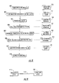
- FIG. 21 is a flow chart showing the steps of the methodology of the present invention.
- the invention resides primarily in prescribed modular arrangements of conventional communication circuits and associated digital signal processing components and attendant supervisory control circuitry therefor, that controls the operations of such circuits and components.
- these modular arrangements may be readily implemented as field programmable gate array (FPGA)-implementation, application specific integrated circuit (ASIC) chip sets, programmable digital signal processors, or general purpose processors.
- FPGA field programmable gate array
- ASIC application specific integrated circuit
- the repeatered wireline fault location scheme of the present invention comprises an extension of the DSL line card installed mechanism disclosed in the above-referenced application, making use of the echo cancellation functionality of transceiver equipment within one or repeaters that are installed along a repeatered telecommunication wireline between a central office and a remote site (customer premises) to perform the fault location measurements, and an overhead channel of one or more intervening links to convey the results of the measurement operations to an upstream (central office) computer facility.
- FIG. 20 A block diagram of such a repeatered link is shown in FIG. 20 as comprising a central office transceiver (HxTUC) 200 , which is coupled to a repeatered wireline link 210 over which communication service is provided to transceiver equipment 220 at a remote site (customer premises).
- link 210 contains one or more repeaters (two repeaters 230 and 240 being shown in the non-limiting example of FIG. 20 ) between the central office transceiver 200 and remote site equipment 220 .
- each repeater's transceiver is provisioned in the same manner as the DSL line card in the central office site, as described with reference to FIGS.
- each repeater is capable of performing the above-described echo-cancellation based fault testing on that segment of wireline to which the repeater is connected (either to another repeater or to the remote site in the case of the last repeater).
- communications between a fault diagnostic repeater and the central office are conducted over an overhead channel, such as an embedded FDL overhead channel.
- the methodology of the present invention may be readily understood by reference to the flow chart of FIG. 21 .
- the routine begins at step 2101 , wherein a fault is detected at the central office. This typically takes place when the central office transceiver (HxTUC) 200 detects a large number of UAS (unavailable seconds), indicating the occurrence of a fault somewhere down the repeatered link.
- the central office line card initially determines the fault resides in that segment of the wireline between the central office transceiver 200 and the first repeater 230 .
- the fault diagnostic routine described above is executed and results reported to the supervisory processing computer (either locally or remotely as described above). For purposes of the present example, it will be assumed that the fault lies downstream of the first (upstream-most) repeater 230 , such as between repeaters 230 and 240 .
- an overhead message is conveyed to the first repeater in step 2103 to determine whether a fault condition exists on the downstream segment of wireline to which repeater 230 is connected. If no fault is detected (the answer to query step 2104 is NO), the message is propagated down the wireline, one intervening unit (repeater) at a time, and the fault query is repeated until a fault is detected (the answer to step 2104 is YES).
- step 2105 that transceiver proceeds to conduct the echo cancellation-based fault diagnostic routine described above.
- the fault diagnostic routine Once the fault diagnostic routine has been completed (the answer to step 2106 is YES), the results of the fault diagnostic operation are then forwarded back up the wireline via the messaging overhead channel (e.g., FDL channel) to the central office HxTUC 200 in step 2107 .
- the reported results are then processed in step 2108 (either locally via a backplane-resident processor or by way of remote computer site, as described above).
- the echo canceler-based fault location mechanism described in the above-referenced applications may be employed extended to a repeatered wireline environment by making use of the functionality of transceiver equipment within one or repeaters installed along the wireline to perform the fault location measurements, and transmitting control and measurement data with respect to such measurements over an overhead channel between each repeater and the upstream (central office) computer facility.
Landscapes
- Engineering & Computer Science (AREA)
- Signal Processing (AREA)
- Cable Transmission Systems, Equalization Of Radio And Reduction Of Echo (AREA)
- Measurement Of Resistance Or Impedance (AREA)
Abstract
Description
Hline(f)≈Hec(f)/[Htx(f)*Hrx(f)]−Hhybrid(f)Hd(f)/[Htx(f)*Hrx(f)]−Hhybrid(f) (1)
Hhybrid(f)≈Hd0(f)/[Htx(f)*Hrx(f)] (2)
Hd0(f) is the echo canceler response as measured when the tip and ring are open. Substituting equation (2) into equation (1) produces equation (3) as:
Hline(f)≈[Hd(f)−Hd0(f)]/Htx(f)*Hrx(f)] (3)
hline(t)≈FFT−1 {[Hd(f)−Hd0(f)]/[Htx(f)*Hrx(f)]} (4)
Hgline(f)≈Hgd(f)/[Htx(f)*Hrx(f)]−Hhybrid(f) (5)
Hbline(f)≈Hbd(f)/[Htx(f)*Hrx(f)]−Hhybrid(f) (6)
Hbline(f)−Hgline(f)=Hfault(f)=[Hbd(f)−Hgd(f)]/[Htx(f)*Hrx(f)] (7)
hfault(f)=FFT −1 {[Hbd(f)−Hgd(f)]/[Htx(f)*Hrx(f)]} (8)
hfault(t)=k*hbd(t)−hgd(t) (9)
DCR=Current DCTap/Initial DCTap (10)
Claims (17)
Priority Applications (1)
| Application Number | Priority Date | Filing Date | Title |
|---|---|---|---|
| US11/612,667 US7624314B1 (en) | 2002-09-18 | 2006-12-19 | Echo canceler-based mechanism for performing and reporting fault diagnostic testing of repeatered telecommunication line |
Applications Claiming Priority (4)
| Application Number | Priority Date | Filing Date | Title |
|---|---|---|---|
| US24636802A | 2002-09-18 | 2002-09-18 | |
| US10/403,321 US7023963B1 (en) | 2002-09-18 | 2003-03-31 | DSL line card echo canceler-based mechanism for locating telecommunication line fault |
| US10/424,304 US7174488B1 (en) | 2002-09-18 | 2003-04-28 | Echo canceler-based mechanism for performing and reporting fault diagnostic testing of repeatered telecommunication line |
| US11/612,667 US7624314B1 (en) | 2002-09-18 | 2006-12-19 | Echo canceler-based mechanism for performing and reporting fault diagnostic testing of repeatered telecommunication line |
Related Parent Applications (1)
| Application Number | Title | Priority Date | Filing Date |
|---|---|---|---|
| US10/424,304 Continuation US7174488B1 (en) | 2002-09-18 | 2003-04-28 | Echo canceler-based mechanism for performing and reporting fault diagnostic testing of repeatered telecommunication line |
Publications (1)
| Publication Number | Publication Date |
|---|---|
| US7624314B1 true US7624314B1 (en) | 2009-11-24 |
Family
ID=35452647
Family Applications (4)
| Application Number | Title | Priority Date | Filing Date |
|---|---|---|---|
| US10/403,321 Expired - Lifetime US7023963B1 (en) | 2002-09-18 | 2003-03-31 | DSL line card echo canceler-based mechanism for locating telecommunication line fault |
| US10/424,304 Expired - Lifetime US7174488B1 (en) | 2002-09-18 | 2003-04-28 | Echo canceler-based mechanism for performing and reporting fault diagnostic testing of repeatered telecommunication line |
| US10/663,631 Expired - Lifetime US6975706B1 (en) | 2002-09-18 | 2003-09-16 | Capacitance measurement-based mechanism for locating open telecommunication line fault |
| US11/612,667 Expired - Lifetime US7624314B1 (en) | 2002-09-18 | 2006-12-19 | Echo canceler-based mechanism for performing and reporting fault diagnostic testing of repeatered telecommunication line |
Family Applications Before (3)
| Application Number | Title | Priority Date | Filing Date |
|---|---|---|---|
| US10/403,321 Expired - Lifetime US7023963B1 (en) | 2002-09-18 | 2003-03-31 | DSL line card echo canceler-based mechanism for locating telecommunication line fault |
| US10/424,304 Expired - Lifetime US7174488B1 (en) | 2002-09-18 | 2003-04-28 | Echo canceler-based mechanism for performing and reporting fault diagnostic testing of repeatered telecommunication line |
| US10/663,631 Expired - Lifetime US6975706B1 (en) | 2002-09-18 | 2003-09-16 | Capacitance measurement-based mechanism for locating open telecommunication line fault |
Country Status (1)
| Country | Link |
|---|---|
| US (4) | US7023963B1 (en) |
Cited By (1)
| Publication number | Priority date | Publication date | Assignee | Title |
|---|---|---|---|---|
| US20080056453A1 (en) * | 2006-08-30 | 2008-03-06 | Philip Specht | Code violation generator and methods of generating code violations |
Families Citing this family (32)
| Publication number | Priority date | Publication date | Assignee | Title |
|---|---|---|---|---|
| US7254217B2 (en) * | 2002-12-12 | 2007-08-07 | Adc Dsl Systems, Inc. | Fault characterization using information indicative of echo |
| US7480367B2 (en) * | 2002-12-12 | 2009-01-20 | Adc Dsl Systems, Inc. | Fault characterization using information indicative of echo |
| US7218730B2 (en) * | 2003-08-13 | 2007-05-15 | International Business Machines Corporation | System and method for analysis and filtering of signals in a telecommunications network |
| US7530112B2 (en) * | 2003-09-10 | 2009-05-05 | Cisco Technology, Inc. | Method and apparatus for providing network security using role-based access control |
| US7460498B2 (en) * | 2003-12-04 | 2008-12-02 | Adtran, Inc. | System and method for detecting anomalies along telecommunication lines |
| US7471897B1 (en) * | 2004-07-16 | 2008-12-30 | Cisco Technology, Inc. | Electrically looped back, fault emulating transceiver module |
| ATE554595T1 (en) * | 2004-12-01 | 2012-05-15 | Ericsson Telefon Ab L M | METHOD AND SYSTEM FOR DETERMINING ONE OR MORE PROPERTIES OF A DIGITAL SUBSCRIBER LINE USING AN ADAPTIVE FIR FILTER |
| KR100697276B1 (en) * | 2005-01-04 | 2007-03-21 | 삼성전자주식회사 | Analog baseband test apparatus and method of mobile communication terminal combining J-tech and memory |
| WO2008070138A2 (en) | 2006-12-05 | 2008-06-12 | Rambus Inc. | Methods and circuits for asymmetric distribution of channel equalization between transceiver devices |
| US8577305B1 (en) | 2007-09-21 | 2013-11-05 | Marvell International Ltd. | Circuits and methods for generating oscillating signals |
| US8588705B1 (en) * | 2007-12-11 | 2013-11-19 | Marvell International Ltd. | System and method of determining Power over Ethernet impairment |
| US8208604B1 (en) | 2008-02-26 | 2012-06-26 | Adtran, Inc. | Systems and methods for diagnosing anomalies along bonded loop communication media |
| US20090319656A1 (en) * | 2008-06-24 | 2009-12-24 | Chen-Yui Yang | Apparatus and method for managing a network |
| US8472968B1 (en) | 2008-08-11 | 2013-06-25 | Marvell International Ltd. | Location-based detection of interference in cellular communications systems |
| WO2010093300A1 (en) * | 2009-02-11 | 2010-08-19 | Telefonaktiebolaget L M Ericsson (Publ) | Methods and devices for transmission line analysis |
| US8255967B2 (en) | 2009-08-21 | 2012-08-28 | At&T Intellectual Property I, Lp | Method and apparatus for high speed data services |
| US9066369B1 (en) | 2009-09-16 | 2015-06-23 | Marvell International Ltd. | Coexisting radio communication |
| US8731183B1 (en) | 2010-04-12 | 2014-05-20 | Adtran, Inc. | System and method for cancelling echo in a communications line |
| GB2480619B (en) * | 2010-05-25 | 2014-02-19 | Vetco Gray Controls Ltd | Electrical fault location determination |
| US9125216B1 (en) | 2011-09-28 | 2015-09-01 | Marvell International Ltd. | Method and apparatus for avoiding interference among multiple radios |
| EP2615813B1 (en) * | 2012-01-10 | 2017-08-30 | Alcatel Lucent | Method and device for identification of an impairment within a telecommunication line |
| US9215708B2 (en) | 2012-02-07 | 2015-12-15 | Marvell World Trade Ltd. | Method and apparatus for multi-network communication |
| US8994926B2 (en) * | 2012-02-14 | 2015-03-31 | Intersil Americas LLC | Optical proximity sensors using echo cancellation techniques to detect one or more objects |
| US8854759B2 (en) | 2012-04-24 | 2014-10-07 | International Business Machines Corporation | Combined soft detection/soft decoding in tape drive storage channels |
| US9450649B2 (en) | 2012-07-02 | 2016-09-20 | Marvell World Trade Ltd. | Shaping near-field transmission signals |
| EP2744116A1 (en) * | 2012-12-13 | 2014-06-18 | British Telecommunications public limited company | Fault localisation |
| US9191496B1 (en) | 2014-04-22 | 2015-11-17 | Adtran, Inc. | Digital subscriber line fault locating systems and methods |
| US9979436B2 (en) * | 2016-08-11 | 2018-05-22 | Positron Access Solutions Corporation | Automatic gain control over copper pairs using daisy-chained amplifiers |
| US10276761B2 (en) | 2017-06-06 | 2019-04-30 | Industrial Technology Research Institute | Photoelectric device package |
| EP3688973A1 (en) * | 2017-09-27 | 2020-08-05 | British Telecommunications Public Limited Company | Fault analysis device |
| CN112362193A (en) * | 2020-10-13 | 2021-02-12 | 华帝股份有限公司 | Open circuit detection method of NTC temperature sensor |
| TWI793486B (en) * | 2020-12-28 | 2023-02-21 | 智原科技股份有限公司 | Echo cancellation device and echo cancellation method thereof applied in communication device |
Citations (7)
| Publication number | Priority date | Publication date | Assignee | Title |
|---|---|---|---|---|
| US4270029A (en) * | 1978-03-23 | 1981-05-26 | Kokusai Denshin Denwa Kabushiki Kaisha | Selection system for digital signal repeaters |
| US4301538A (en) * | 1978-11-02 | 1981-11-17 | Compagnie Industrielle Des Telecommunications Cit-Alcatel | Remote surveillance and fault location unit for pulse regenerator repeaters |
| US4547633A (en) * | 1982-12-09 | 1985-10-15 | International Standard Electric Corporation | Method of and circuit for locating faults in a digital telecommunication subscriber termination |
| US4756005A (en) * | 1986-05-27 | 1988-07-05 | American Telephone And Telegraph Company At&T Bell Laboratories | Digital signal regenerator arranged for fault location |
| US5184081A (en) * | 1990-03-22 | 1993-02-02 | Northern Telecom Europe | Fault location |
| US6697768B2 (en) * | 2001-03-16 | 2004-02-24 | Mindspeed Technologies | Adaptive method and apparatus for transmission line analysis |
| US6807370B2 (en) * | 2001-03-16 | 2004-10-19 | Fujitsu Limited | Optical transmission system |
Family Cites Families (12)
| Publication number | Priority date | Publication date | Assignee | Title |
|---|---|---|---|---|
| US4243959A (en) | 1979-06-21 | 1981-01-06 | Bell Telephone Laboratories, Incorporated | Adaptive filter with tap coefficient leakage |
| US4980887A (en) * | 1988-10-27 | 1990-12-25 | Seiscor Technologies | Digital communication apparatus and method |
| JPH0748681B2 (en) | 1989-02-23 | 1995-05-24 | 日本電気株式会社 | Echo canceller coefficient control method |
| US5111497A (en) * | 1990-09-17 | 1992-05-05 | Raychem Corporation | Alarm and test system for a digital added main line |
| US5244067A (en) | 1992-12-21 | 1993-09-14 | The Whitaker Corporation | Wire runout and splice detector for lead-making machines |
| US5761938A (en) | 1995-11-22 | 1998-06-09 | The Whitaker Corporation | Wire defect detector for a wire handling machine |
| JPH09189740A (en) | 1996-01-10 | 1997-07-22 | Harness Sogo Gijutsu Kenkyusho:Kk | Failure position detection device for wire harness |
| US5774316A (en) | 1996-08-26 | 1998-06-30 | Adtran, Inc. | Ground fault detector for line-powered telephone network |
| US6480532B1 (en) | 1999-07-13 | 2002-11-12 | Stmicroelectronics, Inc. | Echo cancellation for an ADSL modem |
| US6819744B1 (en) * | 1999-09-30 | 2004-11-16 | Telcordia Technologies, Inc. | System and circuitry for measuring echoes on subscriber loops |
| US6868357B2 (en) * | 2001-07-07 | 2005-03-15 | Cynthia M. Furse | Frequency domain reflectometry system for testing wires and cables utilizing in-situ connectors, passive connectivity, cable fray detection, and live wire testing |
| CA2354298A1 (en) | 2001-07-30 | 2003-01-30 | Catena Networks Canada Inc. | G.gen: g.dmt.bis: g.lite.bis: loop diagnostic mode of the initialization procedure |
-
2003
- 2003-03-31 US US10/403,321 patent/US7023963B1/en not_active Expired - Lifetime
- 2003-04-28 US US10/424,304 patent/US7174488B1/en not_active Expired - Lifetime
- 2003-09-16 US US10/663,631 patent/US6975706B1/en not_active Expired - Lifetime
-
2006
- 2006-12-19 US US11/612,667 patent/US7624314B1/en not_active Expired - Lifetime
Patent Citations (7)
| Publication number | Priority date | Publication date | Assignee | Title |
|---|---|---|---|---|
| US4270029A (en) * | 1978-03-23 | 1981-05-26 | Kokusai Denshin Denwa Kabushiki Kaisha | Selection system for digital signal repeaters |
| US4301538A (en) * | 1978-11-02 | 1981-11-17 | Compagnie Industrielle Des Telecommunications Cit-Alcatel | Remote surveillance and fault location unit for pulse regenerator repeaters |
| US4547633A (en) * | 1982-12-09 | 1985-10-15 | International Standard Electric Corporation | Method of and circuit for locating faults in a digital telecommunication subscriber termination |
| US4756005A (en) * | 1986-05-27 | 1988-07-05 | American Telephone And Telegraph Company At&T Bell Laboratories | Digital signal regenerator arranged for fault location |
| US5184081A (en) * | 1990-03-22 | 1993-02-02 | Northern Telecom Europe | Fault location |
| US6697768B2 (en) * | 2001-03-16 | 2004-02-24 | Mindspeed Technologies | Adaptive method and apparatus for transmission line analysis |
| US6807370B2 (en) * | 2001-03-16 | 2004-10-19 | Fujitsu Limited | Optical transmission system |
Cited By (2)
| Publication number | Priority date | Publication date | Assignee | Title |
|---|---|---|---|---|
| US20080056453A1 (en) * | 2006-08-30 | 2008-03-06 | Philip Specht | Code violation generator and methods of generating code violations |
| US8599936B2 (en) * | 2006-08-30 | 2013-12-03 | At&T Intellectual Property I, L.P. | Code violation generator and methods of generating code violations |
Also Published As
| Publication number | Publication date |
|---|---|
| US6975706B1 (en) | 2005-12-13 |
| US7174488B1 (en) | 2007-02-06 |
| US7023963B1 (en) | 2006-04-04 |
Similar Documents
| Publication | Publication Date | Title |
|---|---|---|
| US7624314B1 (en) | Echo canceler-based mechanism for performing and reporting fault diagnostic testing of repeatered telecommunication line | |
| US6538451B1 (en) | Single ended measurement method and system for determining subscriber loop make up | |
| EP1625348B1 (en) | Method and arrangement for estimation of line properties | |
| US7940681B2 (en) | System and method for diagnosing a cabling infrastructure using a PHY | |
| EP2383897A1 (en) | Binder topology identification for a telecommunication network | |
| KR20020079772A (en) | System and Methods For Loop Length and Bridged Tap Length Determination of A Transmission Line and An information storage media | |
| US20130223599A1 (en) | Diagnostic engine for determining global line characteristics of a dsl telecommunication line and method using same | |
| CA2369858C (en) | Single ended measurement method and system for determining subscriber loop make up | |
| WO2013154569A1 (en) | Selt based diagnostic methods & systems for twisted pair telephone lines | |
| CA2378839C (en) | Improved method for determining subscriber loop make-up | |
| EP2464088B1 (en) | Method and testing system for testing an analogue frond end | |
| US9178668B2 (en) | Method and apparatus for detecting improper connections near a customer premises equipment | |
| EP2837169A1 (en) | Selt and delt based diagnostic methods&systems for twisted pair telephone lines | |
| US20240267456A1 (en) | Detecting modem power state change | |
| JP2006510317A (en) | Identifying faults that use echo information | |
| WO2015017325A1 (en) | Method and apparatus for detecting and locating loop impairments | |
| EP2854299B1 (en) | Method and device for analyzing a communication line | |
| CN103999441A (en) | Method and device for identification of an impairment within a telecommunication line | |
| EP3433937B1 (en) | Method and system for estimating crosstalk between electrical transmission lines | |
| EP1734661B1 (en) | Systems and methods for loop length and bridged tap length determination of a transmission line | |
| US20030147506A1 (en) | Single ended line probing in DSL system using combined FDR-TDR approach | |
| GB2367971A (en) | Locating the position of a fault on a telephone line | |
| US20200267255A1 (en) | Fault analysis device | |
| CN104769924A (en) | Method and device for identifying crosstalk |
Legal Events
| Date | Code | Title | Description |
|---|---|---|---|
| STCF | Information on status: patent grant |
Free format text: PATENTED CASE |
|
| FPAY | Fee payment |
Year of fee payment: 4 |
|
| FPAY | Fee payment |
Year of fee payment: 8 |
|
| MAFP | Maintenance fee payment |
Free format text: PAYMENT OF MAINTENANCE FEE, 12TH YEAR, LARGE ENTITY (ORIGINAL EVENT CODE: M1553); ENTITY STATUS OF PATENT OWNER: LARGE ENTITY Year of fee payment: 12 |
|
| AS | Assignment |
Owner name: WELLS FARGO BANK, NATIONAL ASSOCIATION, AS ADMINISTRATIVE AGENT, COLORADO Free format text: SECURITY INTEREST;ASSIGNOR:ADTRAN, INC.;REEL/FRAME:060692/0249 Effective date: 20220718 |