US7615986B2 - Temperature detection function-incorporating current sensor - Google Patents
Temperature detection function-incorporating current sensor Download PDFInfo
- Publication number
- US7615986B2 US7615986B2 US11/723,627 US72362707A US7615986B2 US 7615986 B2 US7615986 B2 US 7615986B2 US 72362707 A US72362707 A US 72362707A US 7615986 B2 US7615986 B2 US 7615986B2
- Authority
- US
- United States
- Prior art keywords
- temperature
- current sensor
- temperature detection
- hall
- detection portion
- Prior art date
- Legal status (The legal status is an assumption and is not a legal conclusion. Google has not performed a legal analysis and makes no representation as to the accuracy of the status listed.)
- Expired - Fee Related, expires
Links
Images


Classifications
-
- G—PHYSICS
- G01—MEASURING; TESTING
- G01R—MEASURING ELECTRIC VARIABLES; MEASURING MAGNETIC VARIABLES
- G01R15/00—Details of measuring arrangements of the types provided for in groups G01R17/00 - G01R29/00, G01R33/00 - G01R33/26 or G01R35/00
- G01R15/14—Adaptations providing voltage or current isolation, e.g. for high-voltage or high-current networks
- G01R15/20—Adaptations providing voltage or current isolation, e.g. for high-voltage or high-current networks using galvano-magnetic devices, e.g. Hall-effect devices, i.e. measuring a magnetic field via the interaction between a current and a magnetic field, e.g. magneto resistive or Hall effect devices
- G01R15/202—Adaptations providing voltage or current isolation, e.g. for high-voltage or high-current networks using galvano-magnetic devices, e.g. Hall-effect devices, i.e. measuring a magnetic field via the interaction between a current and a magnetic field, e.g. magneto resistive or Hall effect devices using Hall-effect devices
-
- G—PHYSICS
- G01—MEASURING; TESTING
- G01R—MEASURING ELECTRIC VARIABLES; MEASURING MAGNETIC VARIABLES
- G01R1/00—Details of instruments or arrangements of the types included in groups G01R5/00 - G01R13/00 and G01R31/00
- G01R1/44—Modifications of instruments for temperature compensation
-
- G—PHYSICS
- G01—MEASURING; TESTING
- G01R—MEASURING ELECTRIC VARIABLES; MEASURING MAGNETIC VARIABLES
- G01R31/00—Arrangements for testing electric properties; Arrangements for locating electric faults; Arrangements for electrical testing characterised by what is being tested not provided for elsewhere
- G01R31/005—Testing of electric installations on transport means
- G01R31/006—Testing of electric installations on transport means on road vehicles, e.g. automobiles or trucks
Definitions
- This invention relates to a current sensor for detecting an electric current by utilizing a Hall effect, and more particularly to a current sensor having a temperature detection function.
- Hall elements for outputting a voltage corresponding to the magnitude of a magnetic field have heretofore been extensively used in current sensors, and in such a current sensor, the amount of current is detected from the magnitude of the magnetic field generated in proportion to the current.
- a current detection is effected by the use of a current sensor, for example, in order to monitor the charging/discharging of a battery or to control a drive motor.
- JP-A-2001-272422 discloses a current detection apparatus for a vehicle in which a current path for a temperature detection element is formed utilizing a board of a current sensor on which a Hall element is mounted. As shown in FIG. 8 , this apparatus includes the current sensor 12 supported on a bus bar 14 connected to a terminal 17 of a battery 13 , and the temperature detection element 20 retained by the bus bar 14 .
- the current sensor 12 comprises a core 32 of a C-shape (i.e., an O-shape part of which is removed or notched to form a gap), the Hall element 33 disposed in the gap of the core 32 , the board 31 on which the Hall element 33 is mounted, and a case 29 housing these parts.
- the core 32 collects magnetic flux from an electric current flowing through the bus bar 14 , to a connector 18 and a cable 16 , and forms parallel flux (which is proportional to the magnitude of the current) in the gap.
- the Hall element 33 converts the magnitude of this magnetic flux into voltage.
- a connection wire 15 of the temperature detection element 20 is connected to the board 31 of the current sensor 12 .
- the current sensor 12 and the temperature detection element 20 can have a common minus-side current path on the board 31 , so that the construction of the circuit is simplified.
- This invention has been made in view of the above circumstances, and an object of the invention is to provide a temperature detection function-incorporating current sensor which has a compact design, and can be easily assembled.
- the Hall IC includes:
- a magnetism detection portion for detecting a magnitude of a magnetic field
- a temperature detection portion for detecting an ambient temperature
- a temperature compensation portion for correcting an error of the magnetism detection portion due to temperature dependency based on the temperature detected by the temperature detection portion
- the detection signal of the magnetism detection portion, corrected with respect to the error, and the temperature signal detected by the temperature detection portion are outputted via the connector terminals to the exterior.
- the temperature detection function-incorporating current sensor of this construction is so constructed as to output the temperature, detected by the temperature detection portion of the Hall IC, to the exterior, and therefore it is not necessary to provide an additional temperature detection part, and also it is not necessary to effect an operation for connecting such a part to a board.
- this temperature detection function-incorporating current sensor can be formed into the bus bar integrated-type in which the Hall IC is disposed in a gap of a core, and a bus bar passing through a central portion of the core is integrally connected with the current sensor.
- this temperature detection function-incorporating current sensor can be formed into the through hole type in which the Hall IC is disposed in a gap in a core, and the current sensor has a through hole passing through a central portion of the core.
- this temperature detection function-incorporating current sensor can be formed into the coreless type in which a magnitude of a magnetic filed which is not collected by a core is detected.
- the temperature detection function-incorporating current sensor of the present invention it is not necessary to provide an additional temperature detection part, and also it is not necessary to effect an operation for connecting such a part to the board, and therefore the product can be formed into a compact design and a low-cost design, and besides the current sensor can be easily assembled.
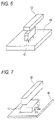
- FIG. 1 is a view showing the appearance of a bus bar integrated-type temperature detection function-incorporating current sensor provided in accordance with a preferred embodiment of the invention.
- FIG. 2 is a view showing the internal structure of the temperature detection function-incorporating current sensor of FIG. 1 .
- FIG. 3 is a view showing the appearance of a Hall IC used in the temperature detection function-incorporating current sensor of the invention.
- FIG. 4 is a block diagram showing the internal structure of the Hall IC of FIG. 3 .
- FIG. 5 is a view showing the appearance of a through hole-type temperature detection function-incorporating current sensor provided in accordance with another embodiment of the invention.
- FIG. 6 is a view showing the appearance of a coreless type temperature detection function-incorporating current sensor provided in accordance with a further embodiment of the invention.
- FIG. 7 is a view showing the appearance of a coreless type temperature detection function-incorporating current sensor provided in accordance with a still further embodiment of the invention.
- FIG. 8 is a view showing a conventional temperature detection function-incorporating current sensor.
- FIG. 1 is a view showing the appearance of a bus bar integrated-type temperature detection function-incorporating current sensor embodying the invention
- FIG. 2 is a view showing the internal structure of the current sensor
- FIG. 3 is a view showing the appearance of a Hall IC used in the temperature detection function-incorporating current sensor
- FIG. 4 is a block diagram showing the internal structure of the Hall IC.
- This current sensor comprises a current sensor body 41 , a connector portion 49 , and a bus bar 60 .
- the bus bar 60 extends through the current sensor body 41 , and is integrally connected with the current sensor by a case of the current sensor body 41 .
- the current sensor body 41 contains therein a core 42 , the Hall IC 43 disposed in a gap of the core 42 , and a board 44 supporting the core 42 and the Hall IC 43 .
- Connector terminals 45 , 46 , 47 and 48 are formed on the board 44 in such a manner that their one end portions are buried in the board 44 . These connector terminals 45 , 46 , 47 and 48 are connected respectively to four terminals 431 , 432 , 433 and 434 ( FIG. 3 ) of the Hall IC 43 via wiring formed on the board 44 . Distal ends of the connector terminals 45 , 46 , 47 and 48 are disposed within the connector portion 49 .
- the Hall IC 43 includes, within a common chip, a magnetism detection portion 438 for detecting magnetism, a temperature detection portion 436 for detecting a temperature, a temperature compensation circuit 437 for correcting an error of the magnetism detection potion 438 due to temperature dependency, and a power circuit 435 for supplying electric power to the magnetism detection portion 438 , the temperature detection portion 436 and the temperature compensation circuit 437 .
- a magnetism signal detected by the magnetism detection portion 438 and a temperature signal detected by the temperature detection portion 436 are outputted respectively as at OUT 1 and OUT 2 .
- a VDD input is applied to the power circuit 435 , and using the remaining terminal, the magnetism detection portion 438 , the temperature detection portion 436 and the temperature compensation circuit 437 are connected to the ground (GND).
- a Hall IC itself which has a temperature detection portion and a temperature compensation circuit is already known, for example, from JP-A-2006-3209.
- a temperature detected by the temperature detection portion is used only for the purpose of correcting an error of magnetism detection due to temperature dependency, and in contrast with the present invention, the detected temperature is not outputted to the exterior of the Hall IC.
- the bus bar 60 is connected, for example, between a battery terminal and a wire harness to which electric power is supplied from a battery, and the connector portion 49 is connected to an ECU.
- the core 42 collects magnetic flux generated from this current, and forms parallel magnetic flux (which is proportional to the magnitude of the current) in the gap.
- the magnetism detection portion 438 of the Hall IC 43 disposed in the gap detects the magnitude of this magnetic flux.
- the temperature detection portion 436 of the Hall IC 43 detects a temperature of the vicinity of the Hall IC 43 , and outputs a signal representative of the detected temperature to the temperature compensation circuit 437 , and also outputs this signal to the exterior of the Hall IC 43 as at OUT 2 .
- the temperature compensation circuit 437 corrects an error of the magnetism detection portion 438 due to temperature dependency, using the temperature signal inputted thereto from the temperature detection portion 436 .
- the magnetism detection portion 438 outputs a magnetism detection signal corrected with respect to this error as at OUT 1 .
- the magnetism signal output (OUT 1 ) outputted from the Hall IC 43 and the temperature signal output (OUT 2 ) are fed to the ECU via the connector portion 49 , and the ECU controls the charging/discharging of the battery into an optimum condition on the basis of these signals.
- this temperature detection function-incorporating current sensor outputs the temperature, detected by the temperature detection portion 436 of the Hall IC 43 , to the exterior, and therefore it is not necessary to provide an additional temperature detection part, and also it is not necessary to effect an operation for connecting such a part to the board.
- This temperature detection function-incorporating current sensor is located in the vicinity of a device to be controlled, and the amount of a current flowing into and out of this device and the temperature are detected, and by using these data, this device can be controlled into an optimum condition.
- the present invention is not limited to the above embodiment, and suitable modifications, improvements, etc., can be made. Furthermore, the material, form, number, disposition, etc., of each of the constituent elements of the above embodiment are arbitrary, and are not limited in so far as the invention can be achieved.
- bus bar integrated-type current sensor is illustrated, the invention can be applied to a current sensor of the through hole-type having a through hole 61 as shown in FIG. 5 and also to coreless type current sensors using no core as shown in FIGS. 6 and 7 .
Landscapes
- Physics & Mathematics (AREA)
- General Physics & Mathematics (AREA)
- Measuring Instrument Details And Bridges, And Automatic Balancing Devices (AREA)
- Measurement Of Current Or Voltage (AREA)
Abstract
Description
Claims (4)
Applications Claiming Priority (2)
| Application Number | Priority Date | Filing Date | Title |
|---|---|---|---|
| JP2006-107640 | 2006-04-10 | ||
| JP2006107640A JP4628987B2 (en) | 2006-04-10 | 2006-04-10 | Current sensor with temperature detection function |
Publications (2)
| Publication Number | Publication Date |
|---|---|
| US20070257659A1 US20070257659A1 (en) | 2007-11-08 |
| US7615986B2 true US7615986B2 (en) | 2009-11-10 |
Family
ID=38514845
Family Applications (1)
| Application Number | Title | Priority Date | Filing Date |
|---|---|---|---|
| US11/723,627 Expired - Fee Related US7615986B2 (en) | 2006-04-10 | 2007-03-21 | Temperature detection function-incorporating current sensor |
Country Status (4)
| Country | Link |
|---|---|
| US (1) | US7615986B2 (en) |
| JP (1) | JP4628987B2 (en) |
| CN (1) | CN101055298B (en) |
| DE (1) | DE102007016069A1 (en) |
Cited By (7)
| Publication number | Priority date | Publication date | Assignee | Title |
|---|---|---|---|---|
| US20090315564A1 (en) * | 2008-04-24 | 2009-12-24 | Andrei Cernasov | Low cost current and temperature sensor |
| US20100090685A1 (en) * | 2008-09-12 | 2010-04-15 | Olivier Andrieu | Wide-range open-loop current sensor |
| US20120217964A1 (en) * | 2011-02-25 | 2012-08-30 | Fujitsu Component Limited | Current sensor, table tap with current sensor, and magnetic substance cover for current sensor |
| US20140077797A1 (en) * | 2012-09-20 | 2014-03-20 | Fujitsu Component Limited | Current sensor |
| US20150022125A1 (en) * | 2012-03-14 | 2015-01-22 | Hitachi Koki Co., Ltd. | Electric tool |
| USD766180S1 (en) * | 2014-08-27 | 2016-09-13 | Lem Intellectual Property Sa | Current transducer |
| USD803154S1 (en) * | 2015-04-21 | 2017-11-21 | Lem Intellectual Property Sa | Current transducer |
Families Citing this family (26)
| Publication number | Priority date | Publication date | Assignee | Title |
|---|---|---|---|---|
| JP4891217B2 (en) * | 2007-12-27 | 2012-03-07 | 株式会社東海理化電機製作所 | Current sensor |
| JP5228679B2 (en) * | 2008-07-31 | 2013-07-03 | 住友電装株式会社 | Electrical junction box with current sensor |
| JP2012018024A (en) * | 2010-07-07 | 2012-01-26 | Alps Green Devices Co Ltd | Current sensor |
| US9176194B2 (en) * | 2010-10-08 | 2015-11-03 | GM Global Technology Operations LLC | Temperature compensation for magnetic determination method for the state of charge of a battery |
| KR101127917B1 (en) * | 2010-11-26 | 2012-03-21 | 한국표준과학연구원 | Apparatus for measuring current and electric power by magnetic field |
| JP5338932B2 (en) * | 2011-07-26 | 2013-11-13 | 株式会社デンソー | Power converter |
| US9461485B2 (en) * | 2011-12-07 | 2016-10-04 | GM Global Technology Operations LLC | Battery magnetic state of charge sensor control algorithm |
| JP2013221796A (en) * | 2012-04-13 | 2013-10-28 | Yazaki Corp | Shunt resistor based current sensor |
| JP2014016297A (en) * | 2012-07-11 | 2014-01-30 | Yazaki Corp | Shunt resistance type current sensor |
| KR101297200B1 (en) * | 2013-04-04 | 2013-08-29 | 주식회사 레티그리드 | Point detecting type current measuring device having function of compensating interference by adjacent bus bar |
| DE102015009603B4 (en) * | 2015-07-24 | 2019-05-09 | Te Connectivity Germany Gmbh | DEVICE FOR MEASURING AN ELECTRIC CURRENT THROUGH A CIRCUIT |
| JP6428573B2 (en) * | 2015-11-13 | 2018-11-28 | トヨタ自動車株式会社 | Power converter |
| JP6805728B2 (en) * | 2015-12-02 | 2020-12-23 | アイシン精機株式会社 | Energization control system |
| CN109791169A (en) * | 2016-11-17 | 2019-05-21 | 株式会社村田制作所 | Current sensor |
| JP6919447B2 (en) | 2017-09-14 | 2021-08-18 | 株式会社デンソー | Reactor temperature estimation method |
| US11137310B2 (en) * | 2017-10-16 | 2021-10-05 | Thomas P. White | Micro-hall effect devices for simultaneous current and temperature measurements for both high and low temperature environments |
| JP2020008459A (en) * | 2018-07-10 | 2020-01-16 | 日本電産トーソク株式会社 | Sensor unit |
| JP2020008460A (en) * | 2018-07-10 | 2020-01-16 | 日本電産トーソク株式会社 | Sensor unit |
| JP7103115B2 (en) * | 2018-09-25 | 2022-07-20 | 株式会社デンソー | Power converter |
| US10914795B2 (en) * | 2019-02-20 | 2021-02-09 | Crocus Technology Inc. | Apparatus and method for magnetic sensor output compensation based upon ambient temperature |
| JP7370164B2 (en) * | 2019-04-23 | 2023-10-27 | 富士電機メーター株式会社 | Current sensor and energy meter |
| US12152945B2 (en) * | 2019-06-05 | 2024-11-26 | Compagnie Generale Des Etablissements Michelin | Temperature sensor for use in rubber mixers |
| KR102421418B1 (en) * | 2020-02-24 | 2022-07-15 | 삼성에스디아이 주식회사 | Battery Energy Storage System Control Unit |
| CN114655014B (en) * | 2020-12-23 | 2023-05-12 | 宇通客车股份有限公司 | Electric drive system, safety early warning method and device of electric drive system |
| CN115014565A (en) * | 2022-06-01 | 2022-09-06 | 宁波赛福汽车制动有限公司 | Coil temperature detection circuit and detection method |
| KR102888678B1 (en) * | 2023-07-27 | 2025-11-27 | 한국전자기술연구원 | Multi-sensor, multi-sensor system and multi-sensor manufacturing method |
Citations (14)
| Publication number | Priority date | Publication date | Assignee | Title |
|---|---|---|---|---|
| US2814015A (en) * | 1955-05-11 | 1957-11-19 | Siemens Ag | Hall generators of increased sensitivity |
| US3825777A (en) * | 1973-02-14 | 1974-07-23 | Ibm | Hall cell with offset voltage control |
| US4682101A (en) * | 1985-02-05 | 1987-07-21 | Lem S.A. | Current transformer for direct and alternating current |
| US4939448A (en) * | 1987-10-16 | 1990-07-03 | Liaisons Electroniques-Mecaniques Lem Sa | Electric current sensing device of the magnetic field compensationtype |
| US5604433A (en) * | 1994-09-06 | 1997-02-18 | Deutsche Itt Industries Gmbh | Offset compensation for magnetic-field sensor with Hall effect device |
| US5615075A (en) * | 1995-05-30 | 1997-03-25 | General Electric Company | AC/DC current sensor for a circuit breaker |
| JP2001272422A (en) | 2000-03-27 | 2001-10-05 | Jeco Co Ltd | Vehicle current detector |
| US20020011841A1 (en) * | 2000-07-07 | 2002-01-31 | Sanken Electric Co., Ltd. | Hall-effect magnetoelectric converter |
| JP2003209935A (en) | 2002-01-15 | 2003-07-25 | Nippon Soken Inc | Charge control device for secondary battery for vehicle |
| US20040080333A1 (en) * | 2001-04-19 | 2004-04-29 | Hans-Wilhelm Klein | Method and apparatus for measurement of the winding temperature of a drive motor |
| US20040138836A1 (en) * | 2002-12-13 | 2004-07-15 | Teruo Ishishita | Apparatus and method for calculating offset value for an electric sensor |
| JP2004254491A (en) | 2003-01-29 | 2004-09-09 | Denso Corp | Vehicular power generation system |
| JP2006003209A (en) * | 2004-06-17 | 2006-01-05 | Setto Engineering:Kk | Current detector |
| JP2006046576A (en) | 2004-08-06 | 2006-02-16 | Nissan Motor Co Ltd | Hybrid vehicle motor heat generation avoidance control device |
Family Cites Families (11)
| Publication number | Priority date | Publication date | Assignee | Title |
|---|---|---|---|---|
| JPH0824201B2 (en) * | 1986-03-03 | 1996-03-06 | 株式会社豊田自動織機製作所 | Magnetic semiconductor element temperature compensation circuit |
| JPH0835993A (en) * | 1994-07-26 | 1996-02-06 | Matsushita Electric Ind Co Ltd | Current detector |
| JPH08288498A (en) * | 1995-04-17 | 1996-11-01 | Honda Motor Co Ltd | Sensor IC |
| JPH0954149A (en) * | 1995-08-17 | 1997-02-25 | Mitsubishi Electric Corp | Semiconductor magnetoelectric converter |
| JP2000324667A (en) * | 1999-05-13 | 2000-11-24 | Yazaki Corp | Electric junction box current detection device |
| JP2002350470A (en) * | 2001-05-23 | 2002-12-04 | Yazaki Corp | Current sensor and current measuring device |
| JP2003060255A (en) * | 2001-08-10 | 2003-02-28 | Asahi Kasei Corp | Hall element and Hall IC |
| JP2004101384A (en) * | 2002-09-10 | 2004-04-02 | Yazaki Corp | Current detector |
| JP4258430B2 (en) * | 2003-06-27 | 2009-04-30 | 日本ビクター株式会社 | Current sensor |
| JP2005265751A (en) * | 2004-03-22 | 2005-09-29 | Renesas Technology Corp | Magnetic detection circuit |
| JP4856862B2 (en) * | 2004-09-08 | 2012-01-18 | 矢崎総業株式会社 | Current sensor |
-
2006
- 2006-04-10 JP JP2006107640A patent/JP4628987B2/en not_active Expired - Fee Related
-
2007
- 2007-03-21 US US11/723,627 patent/US7615986B2/en not_active Expired - Fee Related
- 2007-04-03 DE DE102007016069A patent/DE102007016069A1/en not_active Withdrawn
- 2007-04-10 CN CN2007100911368A patent/CN101055298B/en not_active Expired - Fee Related
Patent Citations (14)
| Publication number | Priority date | Publication date | Assignee | Title |
|---|---|---|---|---|
| US2814015A (en) * | 1955-05-11 | 1957-11-19 | Siemens Ag | Hall generators of increased sensitivity |
| US3825777A (en) * | 1973-02-14 | 1974-07-23 | Ibm | Hall cell with offset voltage control |
| US4682101A (en) * | 1985-02-05 | 1987-07-21 | Lem S.A. | Current transformer for direct and alternating current |
| US4939448A (en) * | 1987-10-16 | 1990-07-03 | Liaisons Electroniques-Mecaniques Lem Sa | Electric current sensing device of the magnetic field compensationtype |
| US5604433A (en) * | 1994-09-06 | 1997-02-18 | Deutsche Itt Industries Gmbh | Offset compensation for magnetic-field sensor with Hall effect device |
| US5615075A (en) * | 1995-05-30 | 1997-03-25 | General Electric Company | AC/DC current sensor for a circuit breaker |
| JP2001272422A (en) | 2000-03-27 | 2001-10-05 | Jeco Co Ltd | Vehicle current detector |
| US20020011841A1 (en) * | 2000-07-07 | 2002-01-31 | Sanken Electric Co., Ltd. | Hall-effect magnetoelectric converter |
| US20040080333A1 (en) * | 2001-04-19 | 2004-04-29 | Hans-Wilhelm Klein | Method and apparatus for measurement of the winding temperature of a drive motor |
| JP2003209935A (en) | 2002-01-15 | 2003-07-25 | Nippon Soken Inc | Charge control device for secondary battery for vehicle |
| US20040138836A1 (en) * | 2002-12-13 | 2004-07-15 | Teruo Ishishita | Apparatus and method for calculating offset value for an electric sensor |
| JP2004254491A (en) | 2003-01-29 | 2004-09-09 | Denso Corp | Vehicular power generation system |
| JP2006003209A (en) * | 2004-06-17 | 2006-01-05 | Setto Engineering:Kk | Current detector |
| JP2006046576A (en) | 2004-08-06 | 2006-02-16 | Nissan Motor Co Ltd | Hybrid vehicle motor heat generation avoidance control device |
Cited By (10)
| Publication number | Priority date | Publication date | Assignee | Title |
|---|---|---|---|---|
| US20090315564A1 (en) * | 2008-04-24 | 2009-12-24 | Andrei Cernasov | Low cost current and temperature sensor |
| US8058876B2 (en) * | 2008-04-24 | 2011-11-15 | Honeywell International, Inc. | Low cost current and temperature sensor |
| US20100090685A1 (en) * | 2008-09-12 | 2010-04-15 | Olivier Andrieu | Wide-range open-loop current sensor |
| US20120217964A1 (en) * | 2011-02-25 | 2012-08-30 | Fujitsu Component Limited | Current sensor, table tap with current sensor, and magnetic substance cover for current sensor |
| US9354280B2 (en) * | 2011-02-25 | 2016-05-31 | Fujitsu Component Limited | Current sensor, table tap with current sensor, and magnetic substance cover for current sensor |
| US20150022125A1 (en) * | 2012-03-14 | 2015-01-22 | Hitachi Koki Co., Ltd. | Electric tool |
| US20140077797A1 (en) * | 2012-09-20 | 2014-03-20 | Fujitsu Component Limited | Current sensor |
| US9250273B2 (en) * | 2012-09-20 | 2016-02-02 | Fujitsu Component Limited | Current sensor |
| USD766180S1 (en) * | 2014-08-27 | 2016-09-13 | Lem Intellectual Property Sa | Current transducer |
| USD803154S1 (en) * | 2015-04-21 | 2017-11-21 | Lem Intellectual Property Sa | Current transducer |
Also Published As
| Publication number | Publication date |
|---|---|
| CN101055298A (en) | 2007-10-17 |
| US20070257659A1 (en) | 2007-11-08 |
| CN101055298B (en) | 2011-06-29 |
| JP4628987B2 (en) | 2011-02-09 |
| DE102007016069A1 (en) | 2007-10-18 |
| JP2007278938A (en) | 2007-10-25 |
Similar Documents
| Publication | Publication Date | Title |
|---|---|---|
| US7615986B2 (en) | Temperature detection function-incorporating current sensor | |
| US8810235B2 (en) | Current sensor and method for manufacturing sensor module for use in current sensor | |
| US8773123B2 (en) | Two-terminal linear sensor | |
| US11067606B2 (en) | Current sensing module | |
| US12000860B2 (en) | Wheel speed sensor having multiple sensing units and wheel bearing comprising same | |
| US6343498B1 (en) | Physical quantity sensor having fault detection function | |
| US20120035824A1 (en) | Abnormality detection device for detection circuit and electric circuit, and detection system and electronic system which uses abnormality detection device | |
| US20130106412A1 (en) | Electrical current sensor | |
| JP5218378B2 (en) | Air flow measurement device | |
| US20110313696A1 (en) | Battery monitoring system | |
| CN102236084A (en) | Calibration method and calibration circuit of current measuring system used for measuring storage battery current in motor vehicle | |
| US9404433B2 (en) | Control device equipped with multiple grounds | |
| US20200158788A1 (en) | Electronic control device | |
| JP5709056B2 (en) | Current detector | |
| WO2010100754A1 (en) | Detection system and electric system | |
| KR102011005B1 (en) | Integrated pressure and water sensor | |
| JP2014119315A (en) | Current sensor and current sensor unit | |
| JP2008170244A (en) | Current sensor | |
| US20140311547A1 (en) | Distributor Load Cell for Determining Phase Current in Photovoltaic Installations | |
| JP3172629B2 (en) | Current / voltage detector | |
| US20090153143A1 (en) | Sensor array for detecting the state of a battery | |
| US7443075B2 (en) | Entrapment detecting system | |
| JP2006145238A (en) | Current sensor | |
| JP2005188932A (en) | Voltage drop type current measuring device | |
| JP2005188972A (en) | Voltage drop type current measuring device |
Legal Events
| Date | Code | Title | Description |
|---|---|---|---|
| AS | Assignment |
Owner name: YAZAKI CORPORATION, JAPAN Free format text: ASSIGNMENT OF ASSIGNORS INTEREST;ASSIGNORS:NOMOTO, SHINGO;TAMURA, SHINICHI;REEL/FRAME:019091/0964 Effective date: 20070227 |
|
| STCF | Information on status: patent grant |
Free format text: PATENTED CASE |
|
| FPAY | Fee payment |
Year of fee payment: 4 |
|
| FPAY | Fee payment |
Year of fee payment: 8 |
|
| FEPP | Fee payment procedure |
Free format text: MAINTENANCE FEE REMINDER MAILED (ORIGINAL EVENT CODE: REM.); ENTITY STATUS OF PATENT OWNER: LARGE ENTITY |
|
| LAPS | Lapse for failure to pay maintenance fees |
Free format text: PATENT EXPIRED FOR FAILURE TO PAY MAINTENANCE FEES (ORIGINAL EVENT CODE: EXP.); ENTITY STATUS OF PATENT OWNER: LARGE ENTITY |
|
| STCH | Information on status: patent discontinuation |
Free format text: PATENT EXPIRED DUE TO NONPAYMENT OF MAINTENANCE FEES UNDER 37 CFR 1.362 |
|
| FP | Lapsed due to failure to pay maintenance fee |
Effective date: 20211110 |