US7570484B1 - System and apparatus for removably mounting hard disk drives - Google Patents
System and apparatus for removably mounting hard disk drives Download PDFInfo
- Publication number
- US7570484B1 US7570484B1 US11/554,408 US55440806A US7570484B1 US 7570484 B1 US7570484 B1 US 7570484B1 US 55440806 A US55440806 A US 55440806A US 7570484 B1 US7570484 B1 US 7570484B1
- Authority
- US
- United States
- Prior art keywords
- disk drive
- drive carrier
- backplane
- cage
- carrier
- Prior art date
- Legal status (The legal status is an assumption and is not a legal conclusion. Google has not performed a legal analysis and makes no representation as to the accuracy of the status listed.)
- Active, expires
Links
- 239000000969 carrier Substances 0.000 claims abstract description 16
- 238000003780 insertion Methods 0.000 claims abstract description 4
- 230000037431 insertion Effects 0.000 claims abstract description 4
- 239000000463 material Substances 0.000 claims description 11
- 239000002184 metal Substances 0.000 claims description 8
- 229920000122 acrylonitrile butadiene styrene Polymers 0.000 claims description 4
- 229920000058 polyacrylate Polymers 0.000 claims description 4
- 229920000515 polycarbonate Polymers 0.000 claims description 4
- 239000004417 polycarbonate Substances 0.000 claims description 4
- 230000000452 restraining effect Effects 0.000 claims description 4
- 238000009434 installation Methods 0.000 claims description 3
- 230000003287 optical effect Effects 0.000 abstract description 15
- 230000000694 effects Effects 0.000 description 8
- 238000010586 diagram Methods 0.000 description 4
- 230000000007 visual effect Effects 0.000 description 4
- 108010028984 3-isopropylmalate dehydratase Proteins 0.000 description 3
- 230000013011 mating Effects 0.000 description 2
- 238000010276 construction Methods 0.000 description 1
- 230000001419 dependent effect Effects 0.000 description 1
- 238000005516 engineering process Methods 0.000 description 1
- 230000006870 function Effects 0.000 description 1
- 238000012986 modification Methods 0.000 description 1
- 230000004048 modification Effects 0.000 description 1
- 229920003023 plastic Polymers 0.000 description 1
- 239000004033 plastic Substances 0.000 description 1
Images


Classifications
-
- G—PHYSICS
- G06—COMPUTING; CALCULATING OR COUNTING
- G06F—ELECTRIC DIGITAL DATA PROCESSING
- G06F1/00—Details not covered by groups G06F3/00 - G06F13/00 and G06F21/00
- G06F1/16—Constructional details or arrangements
- G06F1/18—Packaging or power distribution
- G06F1/183—Internal mounting support structures, e.g. for printed circuit boards, internal connecting means
- G06F1/187—Mounting of fixed and removable disk drives
-
- G—PHYSICS
- G11—INFORMATION STORAGE
- G11B—INFORMATION STORAGE BASED ON RELATIVE MOVEMENT BETWEEN RECORD CARRIER AND TRANSDUCER
- G11B33/00—Constructional parts, details or accessories not provided for in the other groups of this subclass
- G11B33/12—Disposition of constructional parts in the apparatus, e.g. of power supply, of modules
- G11B33/125—Disposition of constructional parts in the apparatus, e.g. of power supply, of modules the apparatus comprising a plurality of recording/reproducing devices, e.g. modular arrangements, arrays of disc drives
Definitions
- Computer system cases come in a wide variety of sizes and shapes. Typical case form factors include desktop and tower cases. Cases such as these typically offer some capacity for expansion. In particular, many cases include three or more 5.25 inch drive bays. Typically, these bays are utilized to hold optical mass storage devices, such as compact disk (“CD”) read-only memory (“CD-ROM”) devices, digital versatile disc (“DVD”) devices, CD or DVD recording devices (such as CD-R or DVD-R devices), or other types of optical mass storage devices.
- CD compact disk
- CD-ROM compact disk
- DVD digital versatile disc
- CD or DVD recording devices such as CD-R or DVD-R devices
- a computer may be configured with a CD-ROM drive, a DVD playback drive, and a CD or DVD recording device.
- a CD-ROM drive may be configured with a CD-ROM drive, a DVD playback drive, and a CD or DVD recording device.
- multifunction optical mass storage devices the need for multiple devices has generally been eliminated.
- a single multifunction device can today provide both DVD playback and CD/DVD recording.
- Other types of multifunction optical mass storage devices provide additional multifunction features.
- a system for removably mounting one or more hard disk drives within a computer system.
- the system includes a disk drive carrier cage configured for removably mounting a disk drive backplane and eight pair of disk drive carrier rails.
- the disk drive carrier cage is sized for insertion into a drive bay having the dimensions of two optical media mass storage devices compatible with a 5.25 inch form factor.
- the dimensions of the disk drive carrier cage are substantially equivalent to 3.33 inches in height, 5.827 inches in width, and 7.984 inches in depth.
- the disk drive carrier cage may be formed from a single piece of metal or other suitably strong and rigid material.
- the system further includes a disk drive backplane mountable within the disk drive carrier cage.
- the disk drive backplane includes eight disk drive connectors, such as serial advanced technology attachment (“SATA”) connectors or serial attached SCSI (“SAS”), for interfacing with compatible connectors on hard disk drives removably mounted along the disk drive carrier rails in disk drive carriers.
- the disk drive backplane further includes eight pair of status indicator lights, such as light emitting diodes (“LEDs”), for providing the location of a disk drive installed within the disk drive carrier cage. Each pair of status indicator lights corresponds to and is located adjacent to a disk drive connector.
- LEDs light emitting diodes
- the disk drive carrier cage includes a top, bottom, rear, first side, and second side.
- the disk drive backplane includes a front side on which the disk drive connectors are mounted and a back side having one or more ports mounted thereon.
- the disk drive backplane is mountable within the disk drive carrier cage by attaching the disk drive backplane to the rear of the disk drive carrier cage.
- the disk drive carrier cage is mountable to a computer system by inserting screws or other fasteners through mounting channels present on the first and second sides of the cage.
- the back of the disk drive carrier cage includes one or more apertures corresponding to the ports mounted on the back side of the drive carrier backplane.
- the ports protrude through the apertures in the disk drive carrier cage.
- the ports mounted on the back side of the disk drive backplane may include power input ports for receiving direct current (“DC”) to power the operation of the disk drive backplane and any hard disk drives connected thereto.
- the ports may also include one or more global output indicator ports for driving external indicator lights when any hard disk drive connected to the disk drive backplane is active or has failed.
- the ports on the back of the disk drive backplane may further include an intelligent platform management interface (“IPMI”) port for communicating management data regarding the hard disk drives connected to the disk drive backplane.
- IPMI intelligent platform management interface
- the ports may further include one or more host bus ports, such as an IPASS port, for connecting the disk drive backplane and any hard disk drives connected thereto to a host computer or host bust adapter (“HBA”).
- HBA host computer or host bust adapter
- the ports may further include power output ports for supplying power to one or more fans attached to the drive carrier cage.
- the drive carrier cage and drive carrier backplane may include airflow apertures for permitting airflow generated by fans mounted to the back of the disk drive carrier cage to pass through and to thereby cool the hard disk drives mounted within the disk drive carrier cage.
- a translucent disk drive carrier for receiving a hard disk drive.
- the disk drive carrier is configured for mounting within the disk drive carrier cage along disk drive carrier rails installed in the disk drive carrier cage.
- the disk drive carrier is constructed from a light transmissive material, such as translucent polycarbonate ABS plastic or acrylic polymer, and has a top, bottom, and a side.
- the disk drive backplane includes light emitting devices for transmitting light along the top of each disk drive carrier along with light emitting devices for transmitting light along the bottom of each disk drive carrier.
- One light may be utilized to indicate the activity of a hard disk drive within the carrier while another light may be utilized to indicate the failure of the hard disk drive within the carrier.
- the system further includes two or more translucent disk drive carrier rails that are removably mountable along a top or bottom of the disk drive carrier cage for receiving the disk drive carriers.
- the disk drive carrier rails include an aperture for receiving a locking tab on the disk drive carrier cage.
- the disk drive carrier rails also include two or more locking protrusions that are inserted into locking apertures in the disk drive carrier cage. Through the use of the locking tab and locking protrusions, the disk drive carrier rails may be removably attached to the disk drive carrier cage without the use of screws or other fasteners.
- the disk drive carrier rails are constructed from a light transmissive material and have a front, back, and side surfaces.
- the disk drive carrier rails are symmetric so that they may be installed along the top or bottom of the disk drive carrier cage.
- the disk drive backplane further includes light emitting devices for transmitting light from the disk drive backplane to the front surface of the disk drive carrier rails when installed in the disk drive carrier cage.
- disk drive carrier rails may be mounted along the top of the disk drive carrier cage and along the bottom of the disk drive carrier cage. Lights on the disk drive backplane can be illuminated to enable quick identification of the corresponding location within the disk drive carrier cage even when a disk drive carrier is not present.
- the disk drive carriers further include one or more latching members.
- the latching members are spring-loaded and mounted at the top front and top bottom of the disk drive carriers.
- the latching members are operative to rotate between a latched position and an unlatched position.
- the disk drive carrier In the unlatched position, the disk drive carrier may be freely inserted or removed from the disk drive carrier cage along the disk drive carrier rails.
- the latched position one end of the latching member protrudes through an aperture in the drive carrier cage, thereby locking the disk drive carrier into the disk drive carrier cage.
- the latching members are symmetrical so that the same member may be utilized in a top or bottom position on the disk drive carriers.
- the disk drive carrier includes locking nubs positioned at locations corresponding to the locations of the mounting screw holes in a hard disk drive.
- the locking nubs protrude into the mounting screw holes of the disk drive thereby securing the hard disk drive in the disk drive carrier without the use of screws or other fasteners.
- FIG. 1 is a perspective view of a system for removably mounting one or more hard disk drives within a computer system provided in one embodiment described herein;
- FIGS. 2A-2B are perspective views of a disk drive carrier cage and a disk drive backplane provided in one implementation described herein;
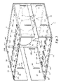
- FIG. 3 is a perspective view of a disk drive carrier cage provided in one implementation described herein;
- FIG. 4 is a metal stamping diagram illustrating a pattern for forming a disk drive carrier cage as provided in one implementation described herein;
- FIG. 5 is a perspective view showing a disk drive carrier and disk drive carrier rails provided in one implementation described herein;
- FIGS. 6A-6B are perspective diagrams illustrating aspects of a disk drive carrier rail provided in one implementation described herein;
- FIGS. 7-8 are two-dimensional side views of a disk drive carrier provided in one implementation described herein;
- FIGS. 9-10 are perspective views illustrating aspects of a disk drive carrier provided in one implementation presented herein;
- FIG. 11 is a perspective view showing a disk drive carrier provided herein with a hard disk drive storage device installed therein;
- FIGS. 12-13 are perspective views showing a disk drive backplane as provided in one implementation described herein;
- FIG. 14 is a cross-sectional view of a disk drive backplane, a disk drive carrier, and disk drive carrier rails as provided in one implementation described herein;
- FIG. 15 is a cross-sectional view showing a disk drive backplane, a disk drive carrier, and disk drive carrier rails as provided in one implementation described herein.
- Embodiments described herein provide apparatus and systems for removably mounting mass storage devices within a computer system.
- references are made to the accompanying drawings that form a part hereof, and in which are shown by way of illustration specific embodiments or examples. Referring now to the drawings, in which like numerals represent like elements throughout the several figures, several illustrative implementations will be described.
- FIG. 1 shows a perspective view of a system for removably mounting one or more hard disk drives within a computer system.
- the system 2 includes a disk drive carrier cage 4 , one or more disk drive carriers 6 each capable of holding a single hard disk drive, and as many as sixteen disk drive carrier rails 8 .
- the disk drive carrier rails 8 are mountable within the disk drive carrier cage 4 . When inserted therein, the disk drive carrier rails 8 allow a disk drive carrier 6 to be slid into and out of the disk drive carrier cage 4 .
- FIG. 1 illustrates only one disk drive carrier 6 and only two disk drive carrier rails 8 A and 8 B. However, it should be appreciated that as many as eight disk drives may be mounted within the disk drive carrier cage 4 through the use of additional disk drive carriers 6 and disk drive carrier rails 8 . Additional details regarding the disk drive carrier cage 4 will be provided below with respect to FIGS. 2-4 . Additional details regarding the disk drive carrier 6 and disk drive carrier rails 8 will be provided below with respect to FIGS. 5-11 .
- FIGS. 2A-2B are perspective views of the disk drive carrier cage 4 and a disk drive backplane 10 that also forms a part of the system 2 in one embodiment.
- the disk drive backplane 10 is mountable within the disk drive carrier cage 4 .
- the disk drive backplane 10 is operative to connect to and interface with hard disk drives mounted within the disk drive carrier cage 4 .
- the disk drive backplane 10 also provides power to the connected hard disk drives, provides an interface for communicating management information regarding the hard disk drives, and performs other functions as described herein. Additional details regarding the structure and operation of the disk drive backplane 10 will be provided below with respect to FIGS. 12-15 .
- the disk drive carrier cage 4 is sized for mounting within a drive bay sized to receive two 5.25 inch form factor optical mass storage devices.
- the size of such 5.25 inch optical mass storage devices is governed by the Small Form Factor (“SFF”) Committee and is described in specification SFF-8551, which is publicly available from the SFF Committee.
- the SFF-8551 specification indicates that the dimensions of a single 5.25 inch optical mass storage device are 5.827 inches in width, 7.984 inches in depth, and 1.665 inches in height. Accordingly, in one implementation described herein, the dimensions of the disk drive carrier cage 4 are substantially equivalent to 5.827 inches in width, 7.984 inches in depth, and 3.33 inches in height. In this manner, the disk drive carrier cage 4 can be installed in a drive bay capable of holding two 5.25 inch form factor optical mass storage devices. It should be appreciated, however, that many of the features described herein are not dependent on the size of the disk drive carrier cage 4 . These features, of course, may be utilized with disk drive carrier cages of other sizes and with other types of removable disk drive systems. Additional details regarding the structure and features of the disk drive carrier cage 4 are provided below with reference to FIG. 3 .
- FIG. 3 is a perspective view of a disk drive carrier cage 4 provided in one implementation described herein.
- the disk drive carrier cage 4 includes a top 12 , bottom 14 , sides 16 and 18 , and a back 20 .
- the disk drive carrier cage 4 may be constructed from a single piece of metal or other suitably strong and rigid material.
- the disk drive carrier cage 4 includes features that allow the disk drive carrier rails 8 to be mounted within the disk drive carrier cage 4 without the use of screws or other fasteners.
- the disk drive carrier cage 4 includes locking tabs that correspond to apertures on the disk drive carrier rails 8 .
- a locking tab is provided for each position within the disk drive carrier cage 4 in which a disk drive carrier 6 may be mounted.
- the locking tabs 24 I- 24 K correspond to the first three positions within the disk drive carrier cage 4 for which drive carriers 6 may be placed.
- two locking apertures 26 are also provided.
- the sides 16 and 18 of the disk drive carrier cage 4 include mounting channels 28 through which a screw or other type of fastener may be inserted to thereby mount the disk drive carrier cage 4 to a suitable case.
- the disk drive carrier cage 4 also includes two carrier locking apertures 22 for each position within the cage 4 at which a disk drive carrier 6 may be inserted.
- each disk drive carrier 6 includes one or more latching members. When placed in a latched position, the latching members protrude through the carrier locking apertures 22 thereby locking the disk drive carrier 6 within the disk drive carrier cage 4 .
- the latching members When placed in an unlatched position, the latching members do not protrude through the carrier locking apertures 22 thereby allowing the disk drive carrier 6 to be freely removed or inserted from the disk drive carrier cage 4 . Additional details regarding the structure and use of the disk drive carriers 6 and the latching members will be provided below with respect to FIGS. 5-9 .
- FIG. 4 is a metal stamping diagram illustrating a pattern for forming a disk drive carrier cage 4 as provided in one implementation described herein.
- the disk drive carrier cage 4 may be constructed from a single piece of metal or other sufficiently strong and rigid material.
- the view shown in FIG. 4 is of a single piece of metal that has been stamped to form the various features of the disk drive carrier cage 4 .
- the score lines 42 A- 42 F indicate the locations at which the metal should be bent to form the disk drive carrier cage 4 as illustrated in FIGS. 1-3 .
- the disk drive carrier cage 4 includes cutouts for forming the carrier locking apertures 22 A- 22 P, the locking tabs 24 A- 24 P, the locking apertures 26 A- 26 EE, and the mounting channels 28 A- 28 H. Cutouts are also provided for forming the airflow apertures 30 A- 30 C. The airflow apertures 30 A- 30 C allow air to pass through the rear 20 of the disk drive carrier cage 4 to cool hard disk drives mounted within the disk drive carrier cage 4 .
- Cutouts may also be provided within the disk drive carrier cage 4 for forming the power and data apertures 32 A- 32 B.
- the power and data apertures permit power headers and host data ports on the disk drive backplane 10 to pass through the rear 20 of the disk drive carrier cage 4 .
- a cutout is also provided on the rear 20 of the disk drive carrier cage 4 for forming an aperture 36 through which an IPMI header on the disk drive backplane 10 may pass.
- Cutouts may also be provided for forming the fan power header apertures 34 A- 34 C. These apertures allow fan power headers provided on the disk drive backplane 10 to pass through the rear 20 of the disk dive carrier cage 4 .
- the fan power headers provide DC power to one or more fans attached to the rear 20 of the disk drive carrier cage 4 .
- the rear 20 of the disk drive carrier cage 4 also includes the fan mounting apertures 38 A- 38 K for receiving a fastener through which the fans are attached to the rear 20 of the disk drive carrier cage 4 .
- the apertures 40 A- 40 H are for receiving a fastener to affix the disk drive backplane 10 to the rear 20 of the disk drive carrier cage 4 .
- locking standoffs are utilized to affix the fans and the disk drive backplane 10 to the rear 20 of the disk drive carrier cage 4 . In this manner, no screws are required to assemble the system shown in FIGS. 1-2B .
- FIG. 5 is a perspective view showing a disk drive carrier 6 and disk drive carrier rails 8 A- 8 B provided in one implementation described herein.
- the disk drive carrier rails 8 A- 8 B are configured to receive the disk drive carrier 6 .
- the disk drive carrier 6 may be slidably inserted into and removed from the disk drive carrier cage 4 .
- An edge of the disk drive carrier rails 8 A- 8 B maintains the disk drive carrier 6 in position and prevents lateral movement of the disk drive carrier 6 .
- the disk drive carrier 6 includes a top 50 , bottom 52 , side 54 , and front 56 .
- the disk drive carrier rails 8 A- 8 B are configured to receive either the top 50 or bottom 52 of the disk drive carrier 6 .
- the disk drive carrier 6 includes two latching members 48 A- 48 B that may be rotated between a latched and an unlatched position. In the latched position, one end of the latching members 48 A- 48 B protrudes through an aperture in the disk drive carrier cage 4 thereby locking the disk drive carrier 6 into the disk drive carrier cage 4 .
- the disk drive carrier 6 In the unlatched position, the disk drive carrier 6 is permitted to freely slide between the disk drive carrier rails 8 A- 8 B for removal or insertion into the disk drive carrier cage 4 . Additional details regarding the disk drive carrier rails 8 A- 8 B are provided below with respect to FIG. 6 . Additional details regarding the structure and operation of the latching members 48 A- 48 B are provided below with respect to FIGS. 7-9 .
- the disk drive carrier 6 is sized to receive a hard disk drive having a 2.5 inch form factor.
- 2.5 inch SAS hard disk drives may be utilized.
- the disk drive backplane 10 is also configured for use with 2.5 inch SAS hard disk drives. It should be appreciated, however, that other types of 2.5 inch disk drives may be utilized. In this manner, as many as eight hard disk drives may be mounted within the disk drive carrier cage 4 within the space of two 5.25 inch form factor optical mass storage devices.
- the disk drive carrier 6 is constructed from a light transmissive material, such as translucent polycarbonate ABS plastic or acrylic polymer.
- a disk drive carrier 6 When a disk drive carrier 6 is inserted into the disk drive carrier cage 4 , light transmitted by status indicator lights on the disk drive backplane 10 is transmitted through the disk drive carrier 6 from the backplane 10 to the front of the disk drive carrier 6 .
- the disk drive backplane 10 includes light emitting devices for transmitting light along the top 50 of each disk drive carrier 6 along with light emitting devices for transmitting light along the bottom 52 of each disk drive carrier 6 .
- One light may be utilized to indicate the activity of a hard disk drive within the carrier 6 while another light may be utilized to indicate the failure of the hard disk drive within the carrier 6 . Additional details regarding the structure and operation of the disk drive backplane 10 in this regard are provided below with respect to FIGS. 12-15 .
- FIGS. 6A-6B are perspective diagrams illustrating aspects of a disk drive carrier rail 8 A provided in one implementation provided herein.
- the disk drive carrier rail 8 A includes a locking tab receiving aperture 44 .
- the locking tabs 24 of the disk drive carrier cage 4 are configured to protrude through the locking tab receiving aperture 44 when the disk drive carrier rail 8 A is installed in the disk drive carrier cage 4 .
- the disk drive carrier rail 8 A may further include multiple protrusions 46 A- 46 B.
- the protrusions 46 A- 46 B are spaced to coincide with the locking apertures 26 of the disk drive carrier cage 4 .
- the protrusions 46 A- 46 B pass into the appropriate locking apertures 26 of the disk drive carrier cage 4 .
- the disk drive carrier rail 8 A may be secured to the disk drive carrier cage 4 without the use of screws or any other fasteners. It should be appreciated that the disk drive carrier rail 8 A is symmetrical so that the same rail may be installed along the top or bottom of the disk drive carrier cage 4 .
- the disk drive carrier rail 8 A is constructed from a light transmissive material and has a front 43 , a back 45 , and a side 47 .
- the light transmissive material may comprise translucent polycarbonate ABS plastic, acrylic polymer, or similar material that provides sufficient strength while allowing the disk drive carrier rail 8 A to remain translucent.
- the disk drive backplane 10 includes light emitting devices for transmitting light from the disk drive backplane 10 to the front 43 of the disk drive carrier rail 8 A when installed in the disk drive carrier cage 4 .
- disk drive carrier rails 8 may be mounted along the top of the disk drive carrier cage 4 and also along the bottom of the disk drive carrier cage 4 .
- Lights on the disk drive backplane 10 can be illuminated to enable quick identification of the corresponding location within the disk drive carrier cage 4 even when a disk drive carrier 6 is not present. Additional details in this regard will be provided below with reference to FIGS. 12-15 .
- FIGS. 7 and 8 are two-dimensional side views of a disk drive carrier 6 provided in one implementation provided herein. Turning now to these figures, additional details regarding a mechanism for locking the disk drive carrier 6 into the disk drive carrier cage 4 will be described.
- the disk drive carrier 6 includes two latching members 48 A and 48 B.
- the latching member 48 A is pivotally attached at the top 50 of the disk drive carrier 6
- the latching member 48 B is pivotally attached at the bottom 52 of the disk drive carrier 6 .
- the front 56 of the disk drive carrier 6 further includes the latches 58 A and 58 B for mating with and thereby restraining the latching members 48 A- 48 B.
- the latching members 48 A and 48 B may be rotated between a latched position and an unlatched position.
- a proximal end 62 B of the member 48 B mates with and is restrained by the latch 58 B.
- a distal end 60 B of the member 48 B also protrudes through the locking aperture 22 of the disk drive carrier cage 4 , thereby locking the disk drive carrier 6 into the cage 4 .
- the proximal end of the member 48 A mates with and is restrained by the latch 58 A in the latched position. In this position, the distal end 60 A of the member 48 A protrudes through a locking aperture in the disk drive carrier cage 4 .
- the latching member 48 B may be removed from the latched position into the unlatched position by slightly moving the latch 58 B in a direction away from the member 48 B thereby releasing the member 48 B.
- the proximal end 62 B of the latching member 48 B does not engage the latch 58 B.
- the distal end 60 B of the member 48 B does not protrude through the locking aperture 22 of the disk drive carrier cage 4 , thereby allowing the disk drive carrier 6 to be freely inserted into or removed from the disk drive carrier cage 4 .
- the latching member 48 A operates in a similar manner. It should be appreciated that the latching members 48 A- 48 B are symmetrical thereby permitting installation and use at either the top or bottom of the disk drive carrier cage 6 . Additional details regarding the construction of the latching members 48 are provided below with respect to FIG. 9 .
- FIG. 9 is a perspective view showing additional aspects of a disk drive carrier 6 provided in one implementation presented herein.
- FIG. 9 illustrates additional aspects of the latching member 48 B and its use in conjunction with the disk drive carrier 6 .
- the latching member 48 B freely rotates between a latched and an unlatched position around a spindle 68 .
- a channel 64 is provided in the latching member for receiving a spring 66 .
- the spring 66 causes the latching member 48 B to become spring-loaded and to remain in the unlatched position by default.
- the spring 66 also provides resistance when the member 48 B is moved from the unlatched position to the latched position.
- FIGS. 10-11 are perspective views showing additional details regarding a disk drive carrier 6 provided herein.
- FIG. 10 illustrates a mechanism utilized in one embodiment presented herein for restraining a hard disk drive within the disk drive carrier 6 .
- this mechanism utilizes the locking nubs 70 A- 70 E to restrain the hard disk drive without the use of screws or other fasteners.
- the locking nubs 70 A- 70 E are located on the top, bottom, and side of each disk drive carrier 6 .
- the locking nubs 70 A- 70 E are positioned at locations corresponding to the locations of mounting screw holes of a hard disk drive when the disk drive is inserted into the disk drive carrier 6 .
- the disk drive carrier 6 is made of plastic, it may be flexed slightly in order to receive the hard disk drive. When the disk drive carrier 6 returns to its non-flexed state, the nubs 70 A- 70 E protrude into the mounting screw holes of the hard disk drive thereby restraining the hard disk drive without the use of mounting screws. It should be appreciated that fewer or more locking nubs may be utilized and at different locations than those illustrated in FIG. 10 .
- FIG. 11 illustrates a hard disk drive 72 mounted within the disk drive carrier 6 .
- the locking nubs protrude into the mounting screw holes on the hard disk drive 72 thereby securing the hard disk drive 72 within the carrier 6 .
- a drive connector 74 on the hard disk drive 72 is accessible from the rear of the carrier 6 for mating with the disk drive backplane 10 . Additional details regarding the disk drive backplane 10 are provided below with respect to FIGS. 12-13 .
- FIGS. 12-13 are perspective views showing a disk drive backplane 10 as provided in one implementation described herein.
- FIG. 12 shows a front side 76 of the disk drive backplane 10 .
- Mounted on the front side 76 of the disk drive backplane 10 are eight disk drive connectors 78 A- 78 H, such as SAS or SATA connectors, for interfacing with compatible connectors on hard disk drives removably mounted along the disk drive carrier rails 8 in disk drive carriers 6 .
- Other types of disk drive connectors may also be utilized.
- the disk drive backplane 10 further includes status indicator lights, such as light emitting diodes (“LEDs”).
- the status indicator lights may be illuminated to show the location of a hard disk drive installed within the drive cage 4 , to indicate the failure of a disk drive, or to indicate the activity of a disk drive.
- Each of the status indicator lights corresponds to and is located adjacent to a disk drive connector.
- the status indicator lights include two LEDs that are mounted on the disk drive backplane 10 adjacent to each disk drive connector. These LEDs are utilized to provide a visual indication of the location of a particular hard disk drive within the cage 4 . These LEDs, referred to herein as “locate LEDs,” are also mounted in such a manner that light emitted from these devices is directed through the disk drive carrier rails 8 installed in the cage 4 . For instance, the locate LEDs 80 A and 80 B are located proximate to the drive connector 78 A.
- the disk drive backplane 10 further includes lights for indicating the activity and failure of a hard disk drive connected to the backplane 10 .
- These lights such as the “activity LEDs” 82 A- 82 H and the “failure LEDs” 84 A- 84 H are mounted in such a manner that light emitted from these devices is directed down the top 50 or bottom 52 of a disk drive carrier 6 when installed in the cage 4 .
- the activity LED 82 A is located proximate to the drive connector 78 A.
- a disk drive carrier 6 When a disk drive carrier 6 is installed at a location in the cage 4 corresponding to the drive connector 78 A and the LED 82 A is illuminated, light emitted from the LED 82 A is visible from the front of the disk drive carrier 6 . In this manner, a visual indication may be provided regarding the activity of the hard disk drive 6 contained within the carrier 6 without the use of an external light pipe. In a similar manner, light emanating from the failure LED 84 A may be transmitted through the disk drive carrier 6 and observed from the front of the carrier. Additional details regarding the use of the disk drive carrier 6 in this manner are provided below with respect to FIGS. 14 and 15 .
- FIG. 13 shows the back side 86 of the disk drive backplane 10 .
- the back side of the disk drive backplane 10 includes several ports. When the disk drive backplane 10 is mounted within the disk drive carrier cage 4 , these ports protrude through the apertures in the disk drive carrier cage 4 described above.
- the ports mounted on the back side of the disk drive backplane may include power input ports 88 A- 88 B for receiving DC to power the operation of the disk drive backplane 10 and any hard disk drives connected thereto.
- the ports may also include one or more global output indicator ports 89 for driving external indicator lights when any hard disk drive connected to the disk drive backplane is active or has failed.
- the ports on the back of the disk drive backplane may further include an IPMI port 92 for communicating management data regarding the hard disk drives connected to the disk drive backplane 10 .
- the ports may further include one or more host bus ports 90 A- 90 B, such as an IPASS port, for connecting the disk drive backplane 10 and any hard disk drives connected thereto to a host computer.
- the IPASS port allows the use of a single cable to connect up to four SAS devices to a host computer. Accordingly, each IPASS port is electrically connected to four of the drive connectors on the disk drive backplane 10 .
- the ports may further include power output ports 94 A- 94 C for supplying power to one or more fans attached to the drive carrier cage 4 .
- the drive carrier cage 4 and drive carrier backplane 10 may include airflow apertures for permitting airflow generated by fans mounted to the back of the disk drive carrier cage 4 to pass through and to thereby cool the hard disk drives mounted within the disk drive carrier cage 4 .
- the disk drive backplane 10 may be affixed to the disk drive carrier cage 4 utilizing locking standoffs 98 A- 98 B thereby eliminating the need for screws or other similar fasteners.
- FIGS. 14 and 15 are two-dimensional cross sectional views of a portion of the disk drive backplane 10 , the disk drive carrier 6 , and the disk drive carrier rail 8 A as provided in one implementation described herein.
- light 100 A emanating from a locate LED 80 A is transmitted through the disk drive carrier rail 8 A and observable at the front of the disk drive cage 4 .
- light 100 B emanating from an activity LED 82 A is transmitted through the disk drive carrier 6 and is observable at the front of the disk drive cage 4 .
Landscapes
- Engineering & Computer Science (AREA)
- Theoretical Computer Science (AREA)
- Computer Hardware Design (AREA)
- Power Engineering (AREA)
- Human Computer Interaction (AREA)
- Physics & Mathematics (AREA)
- General Engineering & Computer Science (AREA)
- General Physics & Mathematics (AREA)
- Automatic Disk Changers (AREA)
Abstract
Description
Claims (19)
Priority Applications (3)
| Application Number | Priority Date | Filing Date | Title |
|---|---|---|---|
| US11/554,408 US7570484B1 (en) | 2006-10-30 | 2006-10-30 | System and apparatus for removably mounting hard disk drives |
| US12/496,021 US7948748B1 (en) | 2006-10-30 | 2009-07-01 | System and apparatus for removably mounting hard disk drives |
| US13/086,266 US8199481B2 (en) | 2006-10-30 | 2011-04-13 | System and apparatus for removably mounting hard disk drives |
Applications Claiming Priority (1)
| Application Number | Priority Date | Filing Date | Title |
|---|---|---|---|
| US11/554,408 US7570484B1 (en) | 2006-10-30 | 2006-10-30 | System and apparatus for removably mounting hard disk drives |
Related Child Applications (2)
| Application Number | Title | Priority Date | Filing Date |
|---|---|---|---|
| US12/496,021 Continuation US7948748B1 (en) | 2006-10-30 | 2009-07-01 | System and apparatus for removably mounting hard disk drives |
| US13/165,904 Division US8545854B2 (en) | 2003-04-23 | 2011-06-22 | Tuberculosis vaccine with improved efficacy |
Publications (1)
| Publication Number | Publication Date |
|---|---|
| US7570484B1 true US7570484B1 (en) | 2009-08-04 |
Family
ID=40910180
Family Applications (3)
| Application Number | Title | Priority Date | Filing Date |
|---|---|---|---|
| US11/554,408 Active 2027-07-14 US7570484B1 (en) | 2006-10-30 | 2006-10-30 | System and apparatus for removably mounting hard disk drives |
| US12/496,021 Active US7948748B1 (en) | 2006-10-30 | 2009-07-01 | System and apparatus for removably mounting hard disk drives |
| US13/086,266 Active US8199481B2 (en) | 2006-10-30 | 2011-04-13 | System and apparatus for removably mounting hard disk drives |
Family Applications After (2)
| Application Number | Title | Priority Date | Filing Date |
|---|---|---|---|
| US12/496,021 Active US7948748B1 (en) | 2006-10-30 | 2009-07-01 | System and apparatus for removably mounting hard disk drives |
| US13/086,266 Active US8199481B2 (en) | 2006-10-30 | 2011-04-13 | System and apparatus for removably mounting hard disk drives |
Country Status (1)
| Country | Link |
|---|---|
| US (3) | US7570484B1 (en) |
Cited By (19)
| Publication number | Priority date | Publication date | Assignee | Title |
|---|---|---|---|---|
| US20080218957A1 (en) * | 2007-03-06 | 2008-09-11 | Micron Technology, Inc. | Memory module and cover therefor |
| US20090234936A1 (en) * | 2008-03-14 | 2009-09-17 | International Business Machines Corporation | Dual-Band Communication Of Management Traffic In A Blade Server System |
| US20100172086A1 (en) * | 2009-01-05 | 2010-07-08 | Hong Fu Jin Precision Industry (Shenzhen) Co., Ltd | Mounting apparatus for disk drive |
| US20100254106A1 (en) * | 2009-04-03 | 2010-10-07 | International Business Machines Corporation | Latching apparatus for facilitating docking of an electronic component |
| US7948748B1 (en) * | 2006-10-30 | 2011-05-24 | American Megatrends, Inc. | System and apparatus for removably mounting hard disk drives |
| US20110234064A1 (en) * | 2010-03-23 | 2011-09-29 | Makley Albert V | Drive Tray |
| US20130070415A1 (en) * | 2011-09-16 | 2013-03-21 | Drobo, Inc. | Push-Push Eject Disk Drive Chassis |
| CN103154847A (en) * | 2010-10-22 | 2013-06-12 | 惠普发展公司,有限责任合伙企业 | Handle module |
| US8493716B2 (en) | 2010-08-27 | 2013-07-23 | International Business Machines Corporation | Locking cage for electronic modules |
| US20140149785A1 (en) * | 2011-10-25 | 2014-05-29 | M. Scott Bunker | Distributed management |
| US20140145571A1 (en) * | 2012-11-29 | 2014-05-29 | Connected Data, Inc. | Assembly for Digital Storage Appliance |
| US20150223364A1 (en) * | 2014-01-31 | 2015-08-06 | Dell Products, Lp | Hard Drive Carrier that Locks in a Shipping Position |
| CN104919527A (en) * | 2013-03-26 | 2015-09-16 | 株式会社日立制作所 | Method for manufacturing storage device and cartridge housing frame |
| US9396156B2 (en) | 2012-04-26 | 2016-07-19 | Connected Data, Inc. | System and method for socially organized storage and shared access to storage appliances |
| US9785205B2 (en) * | 2015-08-26 | 2017-10-10 | Dell Products, L.P. | Quick-release device carrier |
| US20180049342A1 (en) * | 2015-02-20 | 2018-02-15 | Hewlett Packard Enterprise Development Lp | Externally accessible replaceable power source |
| US10127947B2 (en) | 2016-12-23 | 2018-11-13 | Western Digital Technologies, Inc. | Data storage system enclosure with central mounting plate |
| US10601799B2 (en) | 2012-04-26 | 2020-03-24 | Connected Data, Inc. | System and method for visualizing data sharing arrangements for an organization |
| USD957403S1 (en) * | 2020-11-11 | 2022-07-12 | Pavillion Data Systems, Inc. | Drive caddy assembly for a storage device |
Families Citing this family (8)
| Publication number | Priority date | Publication date | Assignee | Title |
|---|---|---|---|---|
| US20130019045A1 (en) * | 2011-07-14 | 2013-01-17 | International Business Machines Corporation | Consolidating Computer Memory Drive Management In A Computing System |
| CN104166612A (en) * | 2013-05-17 | 2014-11-26 | 鸿富锦精密电子(天津)有限公司 | Hard disk indicting system |
| US9141156B2 (en) * | 2013-08-02 | 2015-09-22 | Amazon Technologies, Inc. | Compute node cooling with air fed through backplane |
| US10534411B2 (en) * | 2014-10-02 | 2020-01-14 | Hewlett Packard Enterprise Development Lp | Hard drive carrier |
| US10356957B2 (en) | 2014-10-31 | 2019-07-16 | Hewlett Packard Enterprise Development Lp | Adaptive cooling assembly |
| CN107423184A (en) * | 2017-07-28 | 2017-12-01 | 郑州云海信息技术有限公司 | The method of automatic test server hard-disk interface speed when a kind of hot-swappable |
| US11464129B1 (en) | 2019-11-26 | 2022-10-04 | Seagate Technology Llc | Modular edge storage devices with high speed interconnects |
| CN112037826B (en) * | 2020-09-27 | 2024-08-06 | 记忆科技(深圳)有限公司 | Structure convenient for hard disk maintenance and hard disk maintenance method |
Citations (22)
| Publication number | Priority date | Publication date | Assignee | Title |
|---|---|---|---|---|
| US5680295A (en) * | 1995-11-13 | 1997-10-21 | Ast Research, Inc. | Ventilated backplane for mounting disk drives in computer systems |
| US6064569A (en) * | 1998-11-12 | 2000-05-16 | Dell Usa, L.P. | Computer and hard drive having a multiple drop light pipe |
| US6231224B1 (en) * | 1999-09-22 | 2001-05-15 | International Business Machines Corporation | Light pipe guide and carrier for hard disk drive |
| US6299266B1 (en) * | 1999-10-12 | 2001-10-09 | Hewlett-Packard Company | Mounting arrangement for computer and other units |
| US6373696B1 (en) * | 1998-06-15 | 2002-04-16 | Compaq Computer Corporation | Hard drive cooling using finned heat sink and thermally conductive interface pad |
| US6424526B1 (en) | 2001-06-15 | 2002-07-23 | Cereva Networks. Inc. | High-density disk-array packaging apparatus and method |
| US20020104396A1 (en) * | 2000-04-04 | 2002-08-08 | Megason George D. | Lever system for moving a component within a chassis |
| US6431718B1 (en) * | 1999-09-22 | 2002-08-13 | International Business Machines Corporation | Interconnector and light pipe guide for disk drive and disk drive carrier |
| US6462670B1 (en) * | 2000-10-18 | 2002-10-08 | Compaq Computer Corporation | Server system having front and rear identification |
| US6483107B1 (en) * | 1999-05-11 | 2002-11-19 | Josef Rabinovitz | Canister having a combined guide rail and light pipe system for use in a computer peripheral enclosure |
| US6490153B1 (en) * | 1999-08-06 | 2002-12-03 | California Digital Corporation | Computer system for highly-dense mounting of system components |
| US6608750B2 (en) * | 2001-06-27 | 2003-08-19 | Sun Microsystems, Inc. | Handle-mounted light conduit for a storage device carrier |
| US6661651B1 (en) * | 2001-12-11 | 2003-12-09 | Hewlett-Packard Development Company, L.P. | Mounting of data storage devices with compliant storage module covers |
| US6826056B2 (en) * | 2001-12-11 | 2004-11-30 | Hewlett-Packard Development Company, L.P. | Systems for use with data storage devices |
| US20040264146A1 (en) * | 2003-06-27 | 2004-12-30 | Kerrigan Brian Michael | Handling system for use with a blade in a blade server system |
| US6876547B2 (en) * | 2002-11-14 | 2005-04-05 | Dell Products L.P. | Hard drive carrier |
| US20050201053A1 (en) * | 2004-03-15 | 2005-09-15 | Xyratex Technology Limited | Data storage device carrier and chassis |
| US7015405B2 (en) * | 2004-06-11 | 2006-03-21 | Portwell Inc. | Panel device for ATCA main board |
| US7079381B2 (en) * | 2004-01-07 | 2006-07-18 | International Business Machines Corporation | System and method for aligning and supporting interconnect systems |
| US7216195B1 (en) | 2003-03-29 | 2007-05-08 | Emc Corporation | Architecture for managing disk drives |
| US7295442B2 (en) * | 2001-08-10 | 2007-11-13 | Sun Microsystems, Inc. | System management |
| US7423870B2 (en) * | 2005-11-18 | 2008-09-09 | International Business Machines Corporation | Blade server assembly |
Family Cites Families (7)
| Publication number | Priority date | Publication date | Assignee | Title |
|---|---|---|---|---|
| US6061244A (en) * | 1997-11-10 | 2000-05-09 | Richmount Computers Limited | Carrier for an electronic device |
| TWM241767U (en) * | 2003-03-31 | 2004-08-21 | Cheng-Yu Huang | Plug-in hard disk drive for PC |
| US7405928B2 (en) * | 2004-05-03 | 2008-07-29 | Hewlett-Packard Development Company, L.P. | Removable information storage device enclosure |
| TWM270461U (en) * | 2005-01-07 | 2005-07-11 | Datastor Technology Co Ltd | External storage device with outward projection light source |
| US7242554B1 (en) * | 2006-07-25 | 2007-07-10 | Chern Shi Tech Co., Ltd. | Hard disk drive fixing structure |
| US7570484B1 (en) * | 2006-10-30 | 2009-08-04 | American Megatrends, Inc. | System and apparatus for removably mounting hard disk drives |
| US7362566B1 (en) | 2006-11-28 | 2008-04-22 | American Megatrends, Inc. | External removable hard disk drive system |
-
2006
- 2006-10-30 US US11/554,408 patent/US7570484B1/en active Active
-
2009
- 2009-07-01 US US12/496,021 patent/US7948748B1/en active Active
-
2011
- 2011-04-13 US US13/086,266 patent/US8199481B2/en active Active
Patent Citations (22)
| Publication number | Priority date | Publication date | Assignee | Title |
|---|---|---|---|---|
| US5680295A (en) * | 1995-11-13 | 1997-10-21 | Ast Research, Inc. | Ventilated backplane for mounting disk drives in computer systems |
| US6373696B1 (en) * | 1998-06-15 | 2002-04-16 | Compaq Computer Corporation | Hard drive cooling using finned heat sink and thermally conductive interface pad |
| US6064569A (en) * | 1998-11-12 | 2000-05-16 | Dell Usa, L.P. | Computer and hard drive having a multiple drop light pipe |
| US6483107B1 (en) * | 1999-05-11 | 2002-11-19 | Josef Rabinovitz | Canister having a combined guide rail and light pipe system for use in a computer peripheral enclosure |
| US6490153B1 (en) * | 1999-08-06 | 2002-12-03 | California Digital Corporation | Computer system for highly-dense mounting of system components |
| US6231224B1 (en) * | 1999-09-22 | 2001-05-15 | International Business Machines Corporation | Light pipe guide and carrier for hard disk drive |
| US6431718B1 (en) * | 1999-09-22 | 2002-08-13 | International Business Machines Corporation | Interconnector and light pipe guide for disk drive and disk drive carrier |
| US6299266B1 (en) * | 1999-10-12 | 2001-10-09 | Hewlett-Packard Company | Mounting arrangement for computer and other units |
| US20020104396A1 (en) * | 2000-04-04 | 2002-08-08 | Megason George D. | Lever system for moving a component within a chassis |
| US6462670B1 (en) * | 2000-10-18 | 2002-10-08 | Compaq Computer Corporation | Server system having front and rear identification |
| US6424526B1 (en) | 2001-06-15 | 2002-07-23 | Cereva Networks. Inc. | High-density disk-array packaging apparatus and method |
| US6608750B2 (en) * | 2001-06-27 | 2003-08-19 | Sun Microsystems, Inc. | Handle-mounted light conduit for a storage device carrier |
| US7295442B2 (en) * | 2001-08-10 | 2007-11-13 | Sun Microsystems, Inc. | System management |
| US6661651B1 (en) * | 2001-12-11 | 2003-12-09 | Hewlett-Packard Development Company, L.P. | Mounting of data storage devices with compliant storage module covers |
| US6826056B2 (en) * | 2001-12-11 | 2004-11-30 | Hewlett-Packard Development Company, L.P. | Systems for use with data storage devices |
| US6876547B2 (en) * | 2002-11-14 | 2005-04-05 | Dell Products L.P. | Hard drive carrier |
| US7216195B1 (en) | 2003-03-29 | 2007-05-08 | Emc Corporation | Architecture for managing disk drives |
| US20040264146A1 (en) * | 2003-06-27 | 2004-12-30 | Kerrigan Brian Michael | Handling system for use with a blade in a blade server system |
| US7079381B2 (en) * | 2004-01-07 | 2006-07-18 | International Business Machines Corporation | System and method for aligning and supporting interconnect systems |
| US20050201053A1 (en) * | 2004-03-15 | 2005-09-15 | Xyratex Technology Limited | Data storage device carrier and chassis |
| US7015405B2 (en) * | 2004-06-11 | 2006-03-21 | Portwell Inc. | Panel device for ATCA main board |
| US7423870B2 (en) * | 2005-11-18 | 2008-09-09 | International Business Machines Corporation | Blade server assembly |
Non-Patent Citations (2)
| Title |
|---|
| U.S. Appl. No. 11/563,874, entitled "External Removable Hard Disk Drive System," filed Nov. 28, 2006, Inventor: Clas Gerhard Sivertsen. |
| U.S. Notice of Allowance / Allowability dated Jan. 9, 2008 in U.S. Appl. No. 11/563,874. |
Cited By (33)
| Publication number | Priority date | Publication date | Assignee | Title |
|---|---|---|---|---|
| US7948748B1 (en) * | 2006-10-30 | 2011-05-24 | American Megatrends, Inc. | System and apparatus for removably mounting hard disk drives |
| US20110188196A1 (en) * | 2006-10-30 | 2011-08-04 | American Megatrends, Inc. | System and apparatus for removably mounting hard disk drives |
| US8199481B2 (en) | 2006-10-30 | 2012-06-12 | American Megatrends, Inc. | System and apparatus for removably mounting hard disk drives |
| US20080218957A1 (en) * | 2007-03-06 | 2008-09-11 | Micron Technology, Inc. | Memory module and cover therefor |
| US7881051B2 (en) * | 2007-03-06 | 2011-02-01 | Micron Technology, Inc. | Memory module and cover therefor |
| US20090234936A1 (en) * | 2008-03-14 | 2009-09-17 | International Business Machines Corporation | Dual-Band Communication Of Management Traffic In A Blade Server System |
| US8306652B2 (en) * | 2008-03-14 | 2012-11-06 | International Business Machines Corporation | Dual-band communication of management traffic in a blade server system |
| US8077467B2 (en) * | 2009-01-05 | 2011-12-13 | Hong Fu Jin Precision Industry (Shenzhen) Co., Ltd. | Mounting apparatus for disk drive |
| US20100172086A1 (en) * | 2009-01-05 | 2010-07-08 | Hong Fu Jin Precision Industry (Shenzhen) Co., Ltd | Mounting apparatus for disk drive |
| US8054638B2 (en) * | 2009-04-03 | 2011-11-08 | International Business Machines Corporation | Latching apparatus for facilitating docking of an electronic component |
| US20100254106A1 (en) * | 2009-04-03 | 2010-10-07 | International Business Machines Corporation | Latching apparatus for facilitating docking of an electronic component |
| US9330730B2 (en) * | 2010-03-23 | 2016-05-03 | Lenovo (Singapore) Pte. Ltd. | Drive tray |
| US20110234064A1 (en) * | 2010-03-23 | 2011-09-29 | Makley Albert V | Drive Tray |
| US8493716B2 (en) | 2010-08-27 | 2013-07-23 | International Business Machines Corporation | Locking cage for electronic modules |
| US10101766B2 (en) * | 2010-10-22 | 2018-10-16 | Hewlett-Packard Development Company, L.P. | Handle module |
| CN103154847A (en) * | 2010-10-22 | 2013-06-12 | 惠普发展公司,有限责任合伙企业 | Handle module |
| US20130154288A1 (en) * | 2010-10-22 | 2013-06-20 | Yi-Feng Lin | Handle module |
| CN103154847B (en) * | 2010-10-22 | 2017-07-14 | 惠普发展公司,有限责任合伙企业 | Handle module |
| US8737057B2 (en) * | 2011-09-16 | 2014-05-27 | Drobo, Inc. | Push-push eject disk drive chassis |
| US20130070415A1 (en) * | 2011-09-16 | 2013-03-21 | Drobo, Inc. | Push-Push Eject Disk Drive Chassis |
| US20140149785A1 (en) * | 2011-10-25 | 2014-05-29 | M. Scott Bunker | Distributed management |
| US9396156B2 (en) | 2012-04-26 | 2016-07-19 | Connected Data, Inc. | System and method for socially organized storage and shared access to storage appliances |
| US10601799B2 (en) | 2012-04-26 | 2020-03-24 | Connected Data, Inc. | System and method for visualizing data sharing arrangements for an organization |
| US20140145571A1 (en) * | 2012-11-29 | 2014-05-29 | Connected Data, Inc. | Assembly for Digital Storage Appliance |
| CN104919527B (en) * | 2013-03-26 | 2017-04-26 | 株式会社日立制作所 | Storage device and manufacturing method for canister containment housing |
| CN104919527A (en) * | 2013-03-26 | 2015-09-16 | 株式会社日立制作所 | Method for manufacturing storage device and cartridge housing frame |
| US9437250B2 (en) * | 2014-01-31 | 2016-09-06 | Dell Products, Lp | Hard drive carrier that locks in a shipping position |
| US20150223364A1 (en) * | 2014-01-31 | 2015-08-06 | Dell Products, Lp | Hard Drive Carrier that Locks in a Shipping Position |
| US20180049342A1 (en) * | 2015-02-20 | 2018-02-15 | Hewlett Packard Enterprise Development Lp | Externally accessible replaceable power source |
| US10548237B2 (en) * | 2015-02-20 | 2020-01-28 | Hewlett Packard Enterprise Development Lp | Externally accessible replaceable power source |
| US9785205B2 (en) * | 2015-08-26 | 2017-10-10 | Dell Products, L.P. | Quick-release device carrier |
| US10127947B2 (en) | 2016-12-23 | 2018-11-13 | Western Digital Technologies, Inc. | Data storage system enclosure with central mounting plate |
| USD957403S1 (en) * | 2020-11-11 | 2022-07-12 | Pavillion Data Systems, Inc. | Drive caddy assembly for a storage device |
Also Published As
| Publication number | Publication date |
|---|---|
| US8199481B2 (en) | 2012-06-12 |
| US20110188196A1 (en) | 2011-08-04 |
| US7948748B1 (en) | 2011-05-24 |
Similar Documents
| Publication | Publication Date | Title |
|---|---|---|
| US7570484B1 (en) | System and apparatus for removably mounting hard disk drives | |
| US7362566B1 (en) | External removable hard disk drive system | |
| US7088579B1 (en) | Small form factor disk drive carrier | |
| US6856508B2 (en) | Modular data storage device assembly | |
| US8508928B2 (en) | Incorporation of multiple, 2.5-inch or smaller hard disk drives into a single drive carrier with a single midplane or baseboard connector | |
| US7272012B2 (en) | Removable storage modules | |
| US7139166B2 (en) | Hard drive carrier | |
| US6302714B1 (en) | Slide-activated, spring-loaded ejector for hot-pluggable disk drive carrier | |
| US6906914B2 (en) | Method and apparatus for mounting a backplane in a chassis | |
| US6580604B1 (en) | Peripheral device bay with adapter plates | |
| US10925186B2 (en) | Vertical lift heat transfer device for pluggable modules | |
| US8023258B2 (en) | Computer enclosure and storage device module thereof | |
| CN201051401Y (en) | Storage system for internal connection and external connection | |
| US20040057202A1 (en) | Modular data storage device assembly | |
| JP2017204318A (en) | Two-rack unit chassis and low profile toolless hard disk drive carrier | |
| US7701725B2 (en) | Computer system with riser card | |
| US20190138482A1 (en) | Storage device carrier assembly | |
| US11856725B2 (en) | Device carriers | |
| US8456830B2 (en) | Motherboard and server using the same | |
| US20240288915A1 (en) | Drive adaptor for a drive carrier | |
| US8437133B2 (en) | Latching module mounting system | |
| US7190575B1 (en) | Hard disk drive system and keying method | |
| US20120262874A1 (en) | Motherboard and server using the same | |
| US20130322006A1 (en) | Computer enclosure and mounting assembly for data storage device of the same | |
| US20240256008A1 (en) | Electronic device having keying mechanisms for a drive carrier and a drive cage |
Legal Events
| Date | Code | Title | Description |
|---|---|---|---|
| AS | Assignment |
Owner name: AMERICAN MEGATRENDS, INC., GEORGIA Free format text: ASSIGNMENT OF ASSIGNORS INTEREST;ASSIGNOR:SIVERTSEN, CLAS GERHARD;REEL/FRAME:018455/0138 Effective date: 20061027 |
|
| STCF | Information on status: patent grant |
Free format text: PATENTED CASE |
|
| FPAY | Fee payment |
Year of fee payment: 4 |
|
| FPAY | Fee payment |
Year of fee payment: 8 |
|
| AS | Assignment |
Owner name: AMERICAN MEGATRENDS INTERNATIONAL, LLC, GEORGIA Free format text: ENTITY CONVERSION;ASSIGNOR:AMERICAN MEGATRENDS, INC.;REEL/FRAME:049091/0973 Effective date: 20190211 |
|
| AS | Assignment |
Owner name: MIDCAP FINANCIAL TRUST, AS COLLATERAL AGENT, MARYL Free format text: SECURITY INTEREST;ASSIGNOR:AMERICAN MEGATRENDS INTERNATIONAL, LLC;REEL/FRAME:049087/0266 Effective date: 20190401 Owner name: MIDCAP FINANCIAL TRUST, AS COLLATERAL AGENT, MARYLAND Free format text: SECURITY INTEREST;ASSIGNOR:AMERICAN MEGATRENDS INTERNATIONAL, LLC;REEL/FRAME:049087/0266 Effective date: 20190401 |
|
| MAFP | Maintenance fee payment |
Free format text: PAYMENT OF MAINTENANCE FEE, 12TH YEAR, LARGE ENTITY (ORIGINAL EVENT CODE: M1553); ENTITY STATUS OF PATENT OWNER: LARGE ENTITY Year of fee payment: 12 |
|
| AS | Assignment |
Owner name: AMERICAN MEGATRENDS INTERNATIONAL, LLC, GEORGIA Free format text: RELEASE BY SECURED PARTY;ASSIGNOR:MIDCAP FINANCIAL TRUST;REEL/FRAME:069205/0795 Effective date: 20241017 |
|
| AS | Assignment |
Owner name: BAIN CAPITAL CREDIT, LP, AS ADMINISTRATIVE AGENT AND COLLATERAL AGENT, MASSACHUSETTS Free format text: PATENT SECURITY AGREEMENT;ASSIGNOR:AMERICAN MEGATRENDS INTERNATIONAL, LLC;REEL/FRAME:069229/0834 Effective date: 20241017 |