US7434633B2 - Radially expandable downhole fluid jet cutting tool - Google Patents
Radially expandable downhole fluid jet cutting tool Download PDFInfo
- Publication number
- US7434633B2 US7434633B2 US11/522,692 US52269206A US7434633B2 US 7434633 B2 US7434633 B2 US 7434633B2 US 52269206 A US52269206 A US 52269206A US 7434633 B2 US7434633 B2 US 7434633B2
- Authority
- US
- United States
- Prior art keywords
- cutting
- arm
- cutting tool
- passageway
- housing
- Prior art date
- Legal status (The legal status is an assumption and is not a legal conclusion. Google has not performed a legal analysis and makes no representation as to the accuracy of the status listed.)
- Active
Links
- 238000005520 cutting process Methods 0.000 title claims abstract description 192
- 239000012530 fluid Substances 0.000 title claims abstract description 24
- 239000002173 cutting fluid Substances 0.000 claims abstract description 43
- 238000000034 method Methods 0.000 claims description 17
- 238000004891 communication Methods 0.000 claims description 16
- 238000005086 pumping Methods 0.000 claims description 7
- 239000000463 material Substances 0.000 description 5
- XLYOFNOQVPJJNP-UHFFFAOYSA-N water Substances O XLYOFNOQVPJJNP-UHFFFAOYSA-N 0.000 description 5
- 230000008878 coupling Effects 0.000 description 3
- 238000010168 coupling process Methods 0.000 description 3
- 238000005859 coupling reaction Methods 0.000 description 3
- 239000003082 abrasive agent Substances 0.000 description 2
- 238000005422 blasting Methods 0.000 description 2
- 238000004140 cleaning Methods 0.000 description 2
- 238000012986 modification Methods 0.000 description 2
- 230000004048 modification Effects 0.000 description 2
- 229920000642 polymer Polymers 0.000 description 2
- 230000000712 assembly Effects 0.000 description 1
- 238000000429 assembly Methods 0.000 description 1
- 230000004323 axial length Effects 0.000 description 1
- 238000010276 construction Methods 0.000 description 1
- 230000003247 decreasing effect Effects 0.000 description 1
- 230000007812 deficiency Effects 0.000 description 1
- 238000005553 drilling Methods 0.000 description 1
- 230000000694 effects Effects 0.000 description 1
- 230000003628 erosive effect Effects 0.000 description 1
- 239000002223 garnet Substances 0.000 description 1
- 230000002706 hydrostatic effect Effects 0.000 description 1
- 238000004519 manufacturing process Methods 0.000 description 1
- 229910052751 metal Inorganic materials 0.000 description 1
- 239000002184 metal Substances 0.000 description 1
- 239000002245 particle Substances 0.000 description 1
- 238000005096 rolling process Methods 0.000 description 1
- 239000002002 slurry Substances 0.000 description 1
- 239000007787 solid Substances 0.000 description 1
- 239000000126 substance Substances 0.000 description 1
- UONOETXJSWQNOL-UHFFFAOYSA-N tungsten carbide Chemical compound [W+]#[C-] UONOETXJSWQNOL-UHFFFAOYSA-N 0.000 description 1
Images


Classifications
-
- E—FIXED CONSTRUCTIONS
- E21—EARTH OR ROCK DRILLING; MINING
- E21B—EARTH OR ROCK DRILLING; OBTAINING OIL, GAS, WATER, SOLUBLE OR MELTABLE MATERIALS OR A SLURRY OF MINERALS FROM WELLS
- E21B29/00—Cutting or destroying pipes, packers, plugs or wire lines, located in boreholes or wells, e.g. cutting of damaged pipes, of windows; Deforming of pipes in boreholes or wells; Reconditioning of well casings while in the ground
- E21B29/002—Cutting, e.g. milling, a pipe with a cutter rotating along the circumference of the pipe
- E21B29/005—Cutting, e.g. milling, a pipe with a cutter rotating along the circumference of the pipe with a radially-expansible cutter rotating inside the pipe, e.g. for cutting an annular window
-
- E—FIXED CONSTRUCTIONS
- E21—EARTH OR ROCK DRILLING; MINING
- E21B—EARTH OR ROCK DRILLING; OBTAINING OIL, GAS, WATER, SOLUBLE OR MELTABLE MATERIALS OR A SLURRY OF MINERALS FROM WELLS
- E21B43/00—Methods or apparatus for obtaining oil, gas, water, soluble or meltable materials or a slurry of minerals from wells
- E21B43/11—Perforators; Permeators
- E21B43/114—Perforators using direct fluid action on the wall to be perforated, e.g. abrasive jets
Definitions
- the present invention is directed to a downhole cutting tool and, in particular, a downhole radially expandable fluid jet cutting tool.
- the fluids are conducted through a fluid passage in the arrangement and discharged through a restricted orifice in a jetting nozzle to increase the velocity of fluids and abrasive particles in an attempt to increase the cutting or cleaning effect desired.
- the jetting nozzle is available in a variety of designs and sizes and is normally produced from an extremely hard and/or tough material such as, by way of example only, carbide. It is generally accepted that the closer a jetting nozzle is to the surface to clean or cut the higher the efficiency of the operation.
- the jetting tool apparatus of this patent includes multiple extendible telescoping jetting nozzles that are rotated into position by fluid flowing through the tool. In addition to rotation, the jetting nozzles extend telescopically so as to come in close contact with the cutting surface. After the cutting is completed, however, the nozzles remain extended. They are rotated downward into recesses to facilitate movement of the tool out of the wellbore. In those instances where the tool is to be moved to a new location for continued jetting, the telescopically extended jetting nozzles can not be reconfigured to a lesser extension because the telescoping members cannot be retracted to their original positions.
- the jet cutting tools and methods of cutting a surface of a wellbore of the present invention provide the capability to extend and retract the jetting nozzles for easy and quick relocation and redeployment within a well without the need for removal of the tool from the well; permit the jetting nozzles to be consistently extended to the cutting surface; maintain the jetting nozzles in the appropriate orientation during cutting; permit easy and efficient cutting of casing when passing through a restriction in the casing or when cutting a surface in relatively shallow water depth; permit efficient cutting in multiple locations within conduits having variable inner diameters; and provide the capability of cutting in large diameter conduits and then be redeployed for cutting in small diameter conduits without having to remove the tool from the wellbore.
- the present invention is directed to a jet cutting tool having one or more arms that are extendable radially from the body of the tool.
- Each arm is in fluid communication with a passageway within the tool.
- An actuating member such as a piston, is disposed within the passageway.
- Each arm includes a cutting head disposed on the end.
- the cutting head may include a metal cutting element such as crushed carbide or other carbide elements.
- Cutting fluid such as an abrasive slurry known to persons skilled in the art, is pumped at high pressure down the passageway and moves the piston.
- the piston in turn extends each of the arms until each arm is in contact with the inner wall surface of the cutting surface or casing of the well.
- Cutting fluid is also forced into a length of tubing in fluid communication with the passageway and the cutting head. After extension of the arms to the point where the piston is no longer movable by the cutting fluid, the cutting head is positioned next to, and preferably in contact with, the cutting surface. The cutting fluid is then forced through the length of tubing from the passageway to the cutting head and out of the nozzle at a high pressure. The high pressure of the cutting fluid being expelled from the nozzle of the cutting head cuts the casing or other cutting surface.
- the pressure of the cutting fluid flowing through the passageway is decreased and the piston is retracted. Accordingly, the arms are also retracted so that the jet cutting tool can be moved to a new location and the arms redeployed for additional cutting.
- the retraction and the extension of the arms are fully repeatable such that the jet cutting tool can be used in multiple locations having multiple inner diameter, including cutting narrower portions of casing after cutting wider portions of casing.
- the downhole jet cutting tool comprises a housing having an upper end for connection to a conduit string for running the downhole jet cutting tool into a well, the housing having a passageway for communicating a cutting fluid pumping down the conduit string to the downhole jet cutting tool; an actuating member operatively associated with the passageway whereby the actuating member is actuable by the cutting fluid, the actuating member having an initial position and a plurality of actuated positions; and a jet nozzle assembly, the jet nozzle assembly comprising an arm operatively associated with the actuating member whereby the arm is moved from a retracted position to one of a plurality of extended positions by the actuating member moving from the initial position to a corresponding actuated position, the arm having a cutting end and pivot end, the pivot end being pivotally connected to the housing, and the cutting end having a nozzle for expelling the cutting fluid, wherein the passage
- a further feature of the downhole jet cutting tool is that the cutting head may be pivotally connected to the arm.
- the housing may have an opening leading from the passageway to an exterior portion of the housing, and the arm may have a portion that extends through the opening into the passageway in engagement with the actuating member.
- An additional feature of the downhole jet cutting tool is that the passageway and the nozzle may be in fluid communication with each other through a flexible tubing.
- the flexible tubing may be in fluid communication with the passageway through a port disposed in the housing above the actuating member.
- a further feature of the downhole jet cutting tool is that the housing may include a recess for receiving the jet nozzle assembly when the arm is in the retracted position.
- the actuating member may comprise a piston located in the passageway that is acted on by the cutting fluid flowing down the passageway.
- the actuating member may include a biasing member for biasing the actuating member toward the initial position.
- the biasing member may comprise a coil spring.
- the cutting head may include at least one standoff for contact with the cutting surface in the well while the arm is in one of the extended positions.
- At least one of the at least one standoffs may comprise a roller.
- the roller may have an outer surface with at least one groove disposed on the outer surface.
- at least one of the at least one standoffs may comprise a carbide dome button.
- the downhole jet cutting tool comprises a housing having an upper end for connection to a conduit string for lowering the housing into the tubular member, the housing having a passageway; a piston in the passageway for movement between upper and lower positions; a spring in the passageway for urging the piston toward the upper position; an arm having an upper portion pivotally connected to an exterior portion of the housing at a pivot point, the arm having a cam portion that extends through an opening in the housing into the passageway below the piston so that cutting fluid being pumped down the conduit string moves the piston downward from the upper position, causing the piston to push downward on the cam portion of the arm to pivot a lower portion of the arm outward from the housing; a cutting head with a nozzle attached to the lower portion of the arm for engaging the tubular member; and a flexible tube extending from a port in the housing above the piston to the cutting head for delivering
- one or more of the foregoing advantages have been achieved a method of cutting a casing disposed within a well.
- the method comprising the steps of: (a) running a downhole jet cutting tool on a conduit string into a tubular member of a well to a first location, the downhole jet cutting tool having an actuating member biased toward an initial position and an arm with a cutting head, the arm being pivotally movable from a retracted position by movement of the arm from the initial position; (b) pumping a cutting fluid down the string, which exerts a force on the actuating member to move the actuating member from the initial position, causing the arm to pivot from the retracted position and move the cutting head outward into contact with a surface of the tubular member; (c) continuing to pump the cutting fluid down the string, which flows to and out of the cutting head, resulting in the tubular member being cut; and (d) after the tubular member has been cut, stopping the pumping of cutting fluid down the string,
- a further feature of the method of cutting a casing disposed within a well is that the actuating member in step (a) may comprise a piston. Another feature of the method of cutting a casing disposed within a well is that the method may further comprise the step of moving the downhole jet cutting tool to a second location within the well after completion of step (d) and repeating steps (b) and (c). An additional feature of the method of cutting a casing disposed within a well is that the second location may be narrower than the first location.
- step (a) may comprise pivotally mounting the arm to a housing of the jet cutting tool at a pivot point; and step (b) may comprise exerting a downward force by the actuating member on a portion of the arm inward from the pivot point.
- the jet cutting tools and methods of cutting a surface in a wellbore disclosed herein have one or more of the following advantages: providing the capability of extending and retracting the jetting nozzles for easy and quick relocation and redeployment within a well; permitting the jetting nozzles to be consistently extended to the cutting surface; maintaining the jetting nozzles in the appropriate orientation during cutting; permitting easy and efficient cutting of casing when passing through a restriction in the casing or when cutting a surface in relatively shallow water depth; permitting efficient cutting in multiple locations within conduits having variable inner diameters; and providing the capability of cutting in large diameter conduits and then be redeployed for cutting in small diameter conduits without having to remove the tool from the wellbore.
- FIG. 1 is a cross-sectional view of one embodiment of the jet cutting tool of the present invention shown in its retracted or run-in position.
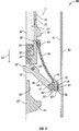
- FIG. 2 is a cross-sectional view of the jet cutting tool illustrated in FIG. 1 shown in its extended or cutting position.
- FIG. 3 is a top view of a cutting head of one specific embodiment of the jet cutting tool of the present invention.
- FIG. 4 is a top view of another cutting head of one specific embodiment of the jet cutting tool of the present invention.
- FIG. 5 is a perspective view of a roller for one embodiment of the jet cutting tools of the present invention.
- Jet cutting tool 20 is shown in its retracted or “run-in” position ( FIG. 1 ) and an extended or cutting position ( FIG. 2 ).
- Jet cuttingtool 20 has housing 22 with passageway 24 extending longitudinally into upper end 21 of housing 22 .
- Upper end 21 is adapted to be connected to string of conduit 10 , such as tubing or drill pipe, through any device or method known to persons of ordinary skill in the art.
- the lower portion of housing 22 is solid, with passageway 24 having a bottom 25 approximately midway along the length of housing 22 .
- Actuating member such as piston 26 is slidingly engaged within passageway 24 of housing 22 .
- Resilient seal 28 provides a seal with piston 26 along the wall of passageway 24 .
- a retaining member such as coil spring 30 is disposed adjacent piston 26 for urging piston 26 upward.
- spring 30 is expanded when jet cutting tool 20 is in its retracted position ( FIG. 1 ) and compressed when jet cutting tool 20 is in its extended position ( FIG. 2 ). Therefore, spring 30 is biased for retaining piston 26 in an initial or upper position in which jet cutting tool 20 is in its retracted position.
- Housing 22 also includes a plurality of rectangular openings 32 (only one shown) extending through its side wall, into which part of a jet nozzle assembly 40 is received when jet cutting tool 20 is in its retracted position. Although only one jet nozzle assembly 40 is shown, typically tool 20 has three or more jet nozzle assemblies 40 . Housing 22 also has a recess 33 on its exterior into which the remaining portion of jet nozzle assembly 40 locates. Opening 32 extends from passageway 24 to recess 33 and has a shorter axial length than recess 33 . The lower end of opening 32 coincides with passageway bottom 25 . Housing 22 also preferably includes radially extending flanges 34 , 36 at its upper and lower ends for protecting jet nozzle assembly 40 when jet cutting tool 20 is in its retracted position.
- Jet nozzle assembly 40 comprises arm 42 , tubing 44 , and cutting head 50 .
- tubing 44 is flexible.
- Tubing 44 is in fluid communication with passageway 24 and cutting head 50 .
- Couplings 45 , 46 attach tubing 44 to passageway 24 and to cutting head 50 , respectively.
- cutting head 50 is pivotally attached to arm 42 by a fastener such as pin 47 or any other device that is capable of attaching cutting head 50 to arm 42 and allowing cutting head 50 to rotate or pivot relative to arm 42 . Accordingly, cutting head 50 can pivot about the point of connection with arm 42 to facilitate better contact with the inner wall surface 61 of casing 60 ( FIG. 2 ).
- a pivot end of arm 42 is connected to housing 22 within the upper end of recess 33 by a fastener such as pin 49 or any other device that is capable of attaching the pivot end of arm 42 to housing 22 and allowing arm 42 to rotate or pivot about pivot pin 49 .
- a lever or cam 48 is integrally formed on the upper end of arm 42 and extends through opening 32 into passageway 24 in contact with the lower end of piston 26 .
- Cam 48 contacts piston 26 at a point that is radially inward and upward from pivot pin 49 , creating a moment arm. Downward movement of piston 26 pushes downward on cam 48 , causing arm 40 to pivot outward to the position shown in FIG. 2 .
- flanges 34 , 36 protect arm 42 , cutting head 50 , and tubing 44 of jet nozzle assembly 40 when arm 42 is in its retracted position ( FIG. 1 ).
- tubing 44 has little or no slack in it when jet cutting tool 20 is in the retracted position. Therefore, the risk of tubing 44 being damaged or broken when jet cutting tool 20 is being run into the well is lessened.
- Cutting head 50 has passage 52 disposed therein. Passage 52 is in fluid communication with coupling 46 and, thus, tubing 44 and passageway 24 . Cutting head 50 also includes opening 54 with, nozzle 56 . As shown in the embodiment of FIGS. 1 and 2 , passage 52 in cutting head 50 includes plug 59 . Plug 59 is used to close one end of passage 52 when passage 52 is formed by drilling all the way through cutting head 50 . In other words, plug 59 may be included if certain methods of manufacturing cutting head 50 are utilized.
- Cutting head 50 also preferably includes one or more standoffs 58 that engage the wall surface of casing 60 ( FIG. 2 ) and facilitate maintaining cutting head 50 and, thus, jet cutting tool 20 in place.
- Standoffs 58 preferably also provide guidance of cutting nozzle 56 in the same track.
- standoffs 58 may comprise dome buttons formed of a hard, wear resistant material such as tungsten carbide.
- standoffs 58 are polymer elements.
- standoffs 66 are bearing units such as rollers 58 having grooves 67 (shown in FIG. 5 ) to facilitate gripping the inner wall surface of casing 60 .
- Standoffs 58 may be arranged in any manner to facilitate the desired type of cut in casing 60 .
- standoffs 58 are rollers 66 for rolling axially along the inner wall surface of casing 60 ( FIG. 2 ) in the direction of arrow 63 and arrow 65 when cutting tool 20 is making an axial cut.
- rollers 66 may be rotated 90 degrees, i.e., perpendicular to rollers 66 shown in FIG. 3 , such that they rotate and, thus, cut, in the direction of arrows 68 and 69 when cutting tool 20 is making a circumferential cut.
- standoffs 58 are ball bearings (not shown) capable of rotating in any direction.
- FIG. 1 shows jet cutting tool 20 in its initial or “run-in” position.
- Each arm 42 is retracted and disposed along housing 22 .
- cutting fluid 62 FIG. 2
- Cutting fluid 62 forces piston 26 to move downward, i.e., in the direction of arrow 63 .
- spring 30 is compressed and piston 26 pushes on cam end 48 and rotates arm 42 around or about pivot pin 49 , causing arm 42 to extend outwardly from housing 22 until standoffs 58 of cutting head 50 contact the inner wall surface of casing 60 as illustrated in FIG. 2 .
- jet cutting tool 20 is placed in its extended or cutting position.
- cutting fluid 62 is forced at a greater pressure through tubing 44 to cutting head 50 where it is focused through passage 52 into and through nozzle 56 and out of opening 54 at a high pressure to cut the inner wall of casing 60 as illustrated by cut 64 ( FIG. 2 ).
- the operator moves conduit string axially to form an axial cut and rotates conduit string 10 to form a circumferential cut.
- cutting fluid 62 propels a rotatable cutting member (not shown) to facilitate cutting of the inner wall surface of casing 60 .
- all of the cutting is performed by cutting fluid 62 being expelled through nozzle 56 at a high pressure.
- Cutting fluids 62 are known to persons skilled in art.
- cutting fluid 62 is an abrasive cutting fluid such as those having a ratio of 1 pound of abrasive material per gallon of water carrier. Suitable abrasive materials are known in the art such as ground garnet material which is available from many known sources.
- the water in cutting fluid 62 can be enhanced with polymers to increase the stream holding profile of the cutting fluid 62 to increase cutting efficiency. Typical cutting rates, but by no means the only cutting rates, are expected to be approximately 1 inch per minute using the foregoing cutting fluid 62 .
- jet cutting tool 20 After casing 60 has been cut as desired by the operator of jet cutting tool 20 , the operator ceases pumping cutting fluid 62 down conduit string 10 . Accordingly, the force being applied to piston 26 in the direction of arrow 63 ceases. When this occurs, spring 30 expands and, thus, moves piston 26 upward in the opposite direction of arrow 63 .
- the weight of jet nozzle assembly 40 causes arm 42 to rotate or pivot about cam end 48 until jet nozzle assembly 40 is received within recess 33 of housing 22 .
- the removal of the pressure of cutting fluid 62 flowing through passageway 24 of jet cutting tool 20 causes jet cutting tool 20 to return to its run-in position.
- jet cutting tool 20 can be moved to a new location for additional cutting.
- the new location can have a smaller diameter and jet cutting tool 20 will properly deploy without the need for removal of jet cutting tool 20 from the well.
- the cutting head is shown as having a rectangular or square shape; however, cutting head can have any shape desired or necessary for providing the type of cut desired by the operator of the jet cutting tool.
- the arm of the jet nozzle assembly and its corresponding recess can have any shape desired or necessary to permit extension and retraction as described above.
- the tubing can be made of any material desired or necessary to facilitate transportation of the cutting fluid from the passageway to the cutting head.
- the size of the opening from the passageway to the tubing, the size of the tubing, the size of the passageway in the cutting head, the size of the nozzle, and the size of the opening in the cutting head can be any size desired or necessary to provide the desired size and depth of cut in the casing.
- the cutting surface is not limited to casing. Other types of conduits, tubings, or structures may be cut using the jet cutting tools described herein.
- spring can be replaced by a pressurized chamber or another device that is biased toward keeping the piston in the retracted position.
- hydrostatic pressure could provide the force for biasing the piston toward the retracted position by having the passageway in the housing continuing to the end of the jet cutting tool where it is opened to the wellbore.
- the piston may be replaced with a valve or other actuating member known to persons of ordinary skill in the art.
- the tubing may be inflexible and the couplings of the tubing to the housing and the cutting head may be flexible joints providing 360 degree movement.
- a top sub may be connected to and placed in communication with the passageway of the housing and the tubing may be in fluid communication with the passageway of the housing through a port in the top sub instead of through a port in the housing.
- a ported collar in fluid communication with the tubing may be secured to the exterior of the top sub to place the tubing in fluid communication with the port in the top sub and, thus, in fluid communication with the passageway. Accordingly, the invention is therefore to be limited only by the scope of the appended claims.
Landscapes
- Life Sciences & Earth Sciences (AREA)
- Engineering & Computer Science (AREA)
- Geology (AREA)
- Mining & Mineral Resources (AREA)
- Physics & Mathematics (AREA)
- Environmental & Geological Engineering (AREA)
- Fluid Mechanics (AREA)
- General Life Sciences & Earth Sciences (AREA)
- Geochemistry & Mineralogy (AREA)
- Perforating, Stamping-Out Or Severing By Means Other Than Cutting (AREA)
Abstract
Description
Claims (19)
Priority Applications (2)
| Application Number | Priority Date | Filing Date | Title |
|---|---|---|---|
| US11/522,692 US7434633B2 (en) | 2006-09-18 | 2006-09-18 | Radially expandable downhole fluid jet cutting tool |
| US12/154,781 US7588101B2 (en) | 2006-09-18 | 2008-05-27 | Radially expandable downhole fluid jet cutting tool having an inflatable member |
Applications Claiming Priority (1)
| Application Number | Priority Date | Filing Date | Title |
|---|---|---|---|
| US11/522,692 US7434633B2 (en) | 2006-09-18 | 2006-09-18 | Radially expandable downhole fluid jet cutting tool |
Related Child Applications (1)
| Application Number | Title | Priority Date | Filing Date |
|---|---|---|---|
| US12/154,781 Continuation-In-Part US7588101B2 (en) | 2006-09-18 | 2008-05-27 | Radially expandable downhole fluid jet cutting tool having an inflatable member |
Publications (2)
| Publication Number | Publication Date |
|---|---|
| US20080066913A1 US20080066913A1 (en) | 2008-03-20 |
| US7434633B2 true US7434633B2 (en) | 2008-10-14 |
Family
ID=39187363
Family Applications (1)
| Application Number | Title | Priority Date | Filing Date |
|---|---|---|---|
| US11/522,692 Active US7434633B2 (en) | 2006-09-18 | 2006-09-18 | Radially expandable downhole fluid jet cutting tool |
Country Status (1)
| Country | Link |
|---|---|
| US (1) | US7434633B2 (en) |
Cited By (14)
| Publication number | Priority date | Publication date | Assignee | Title |
|---|---|---|---|---|
| US20080271892A1 (en) * | 2006-09-18 | 2008-11-06 | Lynde Gerald D | Radially expandable downhole fluid jet cutting tool having an inflatable member |
| RU2487990C1 (en) * | 2011-12-01 | 2013-07-20 | Эльмир Саттарович Кузяев | Device for making perforation tunnels in well |
| CN103562488A (en) * | 2011-05-31 | 2014-02-05 | 韦尔泰克有限公司 | Downhole tubing cutter tool |
| US20150211202A1 (en) * | 2014-01-28 | 2015-07-30 | Paige Melancon | Pile Cutter |
| US20150322745A1 (en) * | 2014-05-09 | 2015-11-12 | Chevron U.S.A. Inc. | Self-Extendable Hydraulic Wellbore Cleaning Tool |
| US9371693B2 (en) | 2012-08-23 | 2016-06-21 | Ramax, Llc | Drill with remotely controlled operating modes and system and method for providing the same |
| US9784085B2 (en) | 2012-09-10 | 2017-10-10 | Schlumberger Technology Corporation | Method for transverse fracturing of a subterranean formation |
| US20180021922A1 (en) * | 2015-02-18 | 2018-01-25 | Ant Applied New Technologies Ag | Water-abrasive cutting system |
| US10094172B2 (en) | 2012-08-23 | 2018-10-09 | Ramax, Llc | Drill with remotely controlled operating modes and system and method for providing the same |
| US10221667B2 (en) | 2013-12-13 | 2019-03-05 | Schlumberger Technology Corporation | Laser cutting with convex deflector |
| US10273787B2 (en) | 2013-12-13 | 2019-04-30 | Schlumberger Technology Corporation | Creating radial slots in a wellbore |
| US11077521B2 (en) | 2014-10-30 | 2021-08-03 | Schlumberger Technology Corporation | Creating radial slots in a subterranean formation |
| US11286738B2 (en) * | 2017-11-15 | 2022-03-29 | Terydon, Inc. | Method for cutting a tube or pipe |
| US11414944B2 (en) | 2017-11-15 | 2022-08-16 | Terydon, Inc. | Down well pipe cutter having a plurality of cutting heads |
Families Citing this family (6)
| Publication number | Priority date | Publication date | Assignee | Title |
|---|---|---|---|---|
| US7832481B2 (en) * | 2008-08-20 | 2010-11-16 | Martindale James G | Fluid perforating/cutting nozzle |
| WO2013126752A1 (en) * | 2012-02-24 | 2013-08-29 | Deltide Energy Services, Llc | Downhole cutting tool having a jetted top bushing |
| US10697263B2 (en) | 2017-11-15 | 2020-06-30 | Terydon, Inc. | Centering device for a utility tool in a tube or pipe |
| US10774606B2 (en) | 2017-11-15 | 2020-09-15 | Terydon, Inc. | Down well pipe cutting device |
| CN112211606B (en) * | 2020-10-12 | 2023-01-31 | 石家庄墨隆煤矿设备有限公司 | Hydraulic cutting device |
| US12000226B2 (en) * | 2020-12-02 | 2024-06-04 | Conocophillips Company | Method and apparatus for milling a window in casing |
Citations (9)
| Publication number | Priority date | Publication date | Assignee | Title |
|---|---|---|---|---|
| US2018285A (en) * | 1934-11-27 | 1935-10-22 | Schweitzer Reuben Richard | Method of well development |
| US5181578A (en) | 1991-11-08 | 1993-01-26 | Lawler O Wayne | Wellbore mineral jetting tool |
| US5363927A (en) * | 1993-09-27 | 1994-11-15 | Frank Robert C | Apparatus and method for hydraulic drilling |
| US5381631A (en) | 1993-04-15 | 1995-01-17 | Flow International Corporation | Method and apparatus for cutting metal casings with an ultrahigh-pressure abrasive fluid jet |
| US5445220A (en) | 1994-02-01 | 1995-08-29 | Allied Oil & Tool Co., Inc. | Apparatus for increasing productivity by cutting openings through casing, cement and the formation rock |
| US5765756A (en) | 1994-09-30 | 1998-06-16 | Tiw Corporation | Abrasive slurry jetting tool and method |
| US6155343A (en) | 1996-10-25 | 2000-12-05 | Baker Hughes Incorporated | System for cutting materials in wellbores |
| US20020050409A1 (en) * | 2000-10-27 | 2002-05-02 | Nackerud Alan L. | Drill bit assembly having pivotal cutter blades |
| US20070151766A1 (en) * | 2005-12-30 | 2007-07-05 | Baker Hughes Incorporated | Mechanical and fluid jet horizontal drilling method and apparatus |
-
2006
- 2006-09-18 US US11/522,692 patent/US7434633B2/en active Active
Patent Citations (9)
| Publication number | Priority date | Publication date | Assignee | Title |
|---|---|---|---|---|
| US2018285A (en) * | 1934-11-27 | 1935-10-22 | Schweitzer Reuben Richard | Method of well development |
| US5181578A (en) | 1991-11-08 | 1993-01-26 | Lawler O Wayne | Wellbore mineral jetting tool |
| US5381631A (en) | 1993-04-15 | 1995-01-17 | Flow International Corporation | Method and apparatus for cutting metal casings with an ultrahigh-pressure abrasive fluid jet |
| US5363927A (en) * | 1993-09-27 | 1994-11-15 | Frank Robert C | Apparatus and method for hydraulic drilling |
| US5445220A (en) | 1994-02-01 | 1995-08-29 | Allied Oil & Tool Co., Inc. | Apparatus for increasing productivity by cutting openings through casing, cement and the formation rock |
| US5765756A (en) | 1994-09-30 | 1998-06-16 | Tiw Corporation | Abrasive slurry jetting tool and method |
| US6155343A (en) | 1996-10-25 | 2000-12-05 | Baker Hughes Incorporated | System for cutting materials in wellbores |
| US20020050409A1 (en) * | 2000-10-27 | 2002-05-02 | Nackerud Alan L. | Drill bit assembly having pivotal cutter blades |
| US20070151766A1 (en) * | 2005-12-30 | 2007-07-05 | Baker Hughes Incorporated | Mechanical and fluid jet horizontal drilling method and apparatus |
Cited By (22)
| Publication number | Priority date | Publication date | Assignee | Title |
|---|---|---|---|---|
| US7588101B2 (en) * | 2006-09-18 | 2009-09-15 | Baker Hughes Incorporated | Radially expandable downhole fluid jet cutting tool having an inflatable member |
| US20080271892A1 (en) * | 2006-09-18 | 2008-11-06 | Lynde Gerald D | Radially expandable downhole fluid jet cutting tool having an inflatable member |
| CN103562488A (en) * | 2011-05-31 | 2014-02-05 | 韦尔泰克有限公司 | Downhole tubing cutter tool |
| CN103562488B (en) * | 2011-05-31 | 2016-08-17 | 韦尔泰克有限公司 | Down-hole pipe fitting cutting tool |
| US9441436B2 (en) | 2011-05-31 | 2016-09-13 | Welltec A/S | Downhole tubing cutter tool |
| RU2487990C1 (en) * | 2011-12-01 | 2013-07-20 | Эльмир Саттарович Кузяев | Device for making perforation tunnels in well |
| US10683704B2 (en) | 2012-08-23 | 2020-06-16 | Ramax, Llc | Drill with remotely controlled operating modes and system and method for providing the same |
| US10094172B2 (en) | 2012-08-23 | 2018-10-09 | Ramax, Llc | Drill with remotely controlled operating modes and system and method for providing the same |
| US9371693B2 (en) | 2012-08-23 | 2016-06-21 | Ramax, Llc | Drill with remotely controlled operating modes and system and method for providing the same |
| US9410376B2 (en) | 2012-08-23 | 2016-08-09 | Ramax, Llc | Drill with remotely controlled operating modes and system and method for providing the same |
| US9784085B2 (en) | 2012-09-10 | 2017-10-10 | Schlumberger Technology Corporation | Method for transverse fracturing of a subterranean formation |
| US10221667B2 (en) | 2013-12-13 | 2019-03-05 | Schlumberger Technology Corporation | Laser cutting with convex deflector |
| US10273787B2 (en) | 2013-12-13 | 2019-04-30 | Schlumberger Technology Corporation | Creating radial slots in a wellbore |
| US9464399B2 (en) * | 2014-01-28 | 2016-10-11 | Ats Smart Solutions, Llc | Pile cutter |
| US20150211202A1 (en) * | 2014-01-28 | 2015-07-30 | Paige Melancon | Pile Cutter |
| US9371716B2 (en) * | 2014-05-09 | 2016-06-21 | Chevron U.S.A. Inc. | Self-extendable hydraulic wellbore cleaning tool |
| US20150322745A1 (en) * | 2014-05-09 | 2015-11-12 | Chevron U.S.A. Inc. | Self-Extendable Hydraulic Wellbore Cleaning Tool |
| US11077521B2 (en) | 2014-10-30 | 2021-08-03 | Schlumberger Technology Corporation | Creating radial slots in a subterranean formation |
| US20180021922A1 (en) * | 2015-02-18 | 2018-01-25 | Ant Applied New Technologies Ag | Water-abrasive cutting system |
| US10525569B2 (en) * | 2015-02-18 | 2020-01-07 | Ant Applied New Technologies Ag | Water-abrasive cutting system |
| US11286738B2 (en) * | 2017-11-15 | 2022-03-29 | Terydon, Inc. | Method for cutting a tube or pipe |
| US11414944B2 (en) | 2017-11-15 | 2022-08-16 | Terydon, Inc. | Down well pipe cutter having a plurality of cutting heads |
Also Published As
| Publication number | Publication date |
|---|---|
| US20080066913A1 (en) | 2008-03-20 |
Similar Documents
| Publication | Publication Date | Title |
|---|---|---|
| US7434633B2 (en) | Radially expandable downhole fluid jet cutting tool | |
| US7588101B2 (en) | Radially expandable downhole fluid jet cutting tool having an inflatable member | |
| US5195585A (en) | Wireline retrievable jet cleaning tool | |
| EP1497526B1 (en) | Bi-directional thruster pig apparatus and method of utilizing same | |
| CA2794324C (en) | Horizontal waterjet drilling method | |
| US8479821B2 (en) | Method and apparatus for removal of pigs, deposits and other debris from pipelines and wellbores | |
| US8267199B2 (en) | Perforating and jet drilling method and apparatus | |
| US20200024936A1 (en) | Method of subterranean fracturing | |
| US6401813B1 (en) | Wellhead cleanup tool | |
| US7007865B2 (en) | Self-adjusting nozzle | |
| US20010045282A1 (en) | Combined notching and jetting methods and related apparatus | |
| US20220178227A1 (en) | Downhole cleaning apparatus | |
| WO2003006787A1 (en) | Liner brushing and conditioning tool | |
| US20210207448A1 (en) | Apparatus for Downhole Milling of Material of a Well Wall | |
| US10557326B2 (en) | Systems and methods for stuck pipe mitigation | |
| US11933141B2 (en) | Multiple cycle deployable and retractable downhole scraper or brush | |
| CN212249964U (en) | Controllable circulating pigging pup joint device | |
| HK1074474B (en) | Bi-directional thruster pig apparatus and method of utilizing same | |
| HK1074474A1 (en) | Bi-directional thruster pig apparatus and method of utilizing same | |
| ZA200406125B (en) | Bi-directional thruster pig apparatus and method of utilizing same. |
Legal Events
| Date | Code | Title | Description |
|---|---|---|---|
| AS | Assignment |
Owner name: BAKER HUGHES INCORPORATED, TEXAS Free format text: ASSIGNMENT OF ASSIGNORS INTEREST;ASSIGNORS:LYNDE, GERALD D.;LAIRD, MARY L.;REEL/FRAME:018800/0700 Effective date: 20061024 |
|
| FEPP | Fee payment procedure |
Free format text: PAYOR NUMBER ASSIGNED (ORIGINAL EVENT CODE: ASPN); ENTITY STATUS OF PATENT OWNER: LARGE ENTITY |
|
| STCF | Information on status: patent grant |
Free format text: PATENTED CASE |
|
| FPAY | Fee payment |
Year of fee payment: 4 |
|
| FPAY | Fee payment |
Year of fee payment: 8 |
|
| MAFP | Maintenance fee payment |
Free format text: PAYMENT OF MAINTENANCE FEE, 12TH YEAR, LARGE ENTITY (ORIGINAL EVENT CODE: M1553); ENTITY STATUS OF PATENT OWNER: LARGE ENTITY Year of fee payment: 12 |
|
| AS | Assignment |
Owner name: BAKER HUGHES, A GE COMPANY, LLC, TEXAS Free format text: CHANGE OF NAME;ASSIGNOR:BAKER HUGHES INCORPORATED;REEL/FRAME:059480/0512 Effective date: 20170703 |
|
| AS | Assignment |
Owner name: BAKER HUGHES HOLDINGS LLC, TEXAS Free format text: CHANGE OF NAME;ASSIGNOR:BAKER HUGHES, A GE COMPANY, LLC;REEL/FRAME:059595/0759 Effective date: 20200413 |