US742772A - Vertical-feed transverse-cutting machine. - Google Patents
Vertical-feed transverse-cutting machine. Download PDFInfo
- Publication number
- US742772A US742772A US1902123069A US742772A US 742772 A US742772 A US 742772A US 1902123069 A US1902123069 A US 1902123069A US 742772 A US742772 A US 742772A
- Authority
- US
- United States
- Prior art keywords
- saw
- tool
- shield
- carrier
- vertical
- Prior art date
- Legal status (The legal status is an assumption and is not a legal conclusion. Google has not performed a legal analysis and makes no representation as to the accuracy of the status listed.)
- Expired - Lifetime
Links
Images


Classifications
-
- C—CHEMISTRY; METALLURGY
- C14—SKINS; HIDES; PELTS; LEATHER
- C14B—MECHANICAL TREATMENT OR PROCESSING OF SKINS, HIDES OR LEATHER IN GENERAL; PELT-SHEARING MACHINES; INTESTINE-SPLITTING MACHINES
- C14B5/00—Clicking, perforating, or cutting leather
-
- Y—GENERAL TAGGING OF NEW TECHNOLOGICAL DEVELOPMENTS; GENERAL TAGGING OF CROSS-SECTIONAL TECHNOLOGIES SPANNING OVER SEVERAL SECTIONS OF THE IPC; TECHNICAL SUBJECTS COVERED BY FORMER USPC CROSS-REFERENCE ART COLLECTIONS [XRACs] AND DIGESTS
- Y10—TECHNICAL SUBJECTS COVERED BY FORMER USPC
- Y10T—TECHNICAL SUBJECTS COVERED BY FORMER US CLASSIFICATION
- Y10T83/00—Cutting
- Y10T83/727—With means to guide moving work
- Y10T83/74—Adapted to permit maneuvering of work at tool zone
-
- Y—GENERAL TAGGING OF NEW TECHNOLOGICAL DEVELOPMENTS; GENERAL TAGGING OF CROSS-SECTIONAL TECHNOLOGIES SPANNING OVER SEVERAL SECTIONS OF THE IPC; TECHNICAL SUBJECTS COVERED BY FORMER USPC CROSS-REFERENCE ART COLLECTIONS [XRACs] AND DIGESTS
- Y10—TECHNICAL SUBJECTS COVERED BY FORMER USPC
- Y10T—TECHNICAL SUBJECTS COVERED BY FORMER US CLASSIFICATION
- Y10T83/00—Cutting
- Y10T83/727—With means to guide moving work
- Y10T83/741—With movable or yieldable guide element
-
- Y—GENERAL TAGGING OF NEW TECHNOLOGICAL DEVELOPMENTS; GENERAL TAGGING OF CROSS-SECTIONAL TECHNOLOGIES SPANNING OVER SEVERAL SECTIONS OF THE IPC; TECHNICAL SUBJECTS COVERED BY FORMER USPC CROSS-REFERENCE ART COLLECTIONS [XRACs] AND DIGESTS
- Y10—TECHNICAL SUBJECTS COVERED BY FORMER USPC
- Y10T—TECHNICAL SUBJECTS COVERED BY FORMER US CLASSIFICATION
- Y10T83/00—Cutting
- Y10T83/768—Rotatable disc tool pair or tool and carrier
- Y10T83/7684—With means to support work relative to tool[s]
- Y10T83/7693—Tool moved relative to work-support during cutting
-
- Y—GENERAL TAGGING OF NEW TECHNOLOGICAL DEVELOPMENTS; GENERAL TAGGING OF CROSS-SECTIONAL TECHNOLOGIES SPANNING OVER SEVERAL SECTIONS OF THE IPC; TECHNICAL SUBJECTS COVERED BY FORMER USPC CROSS-REFERENCE ART COLLECTIONS [XRACs] AND DIGESTS
- Y10—TECHNICAL SUBJECTS COVERED BY FORMER USPC
- Y10T—TECHNICAL SUBJECTS COVERED BY FORMER US CLASSIFICATION
- Y10T83/00—Cutting
- Y10T83/768—Rotatable disc tool pair or tool and carrier
- Y10T83/7755—Carrier for rotatable tool movable during cutting
- Y10T83/7759—Unicyclic movement
Definitions
- VERTICAL FEED TR ANSVERSE CUTTING MACHINE.
- SHEETS-SHEET 1- w NORRIS Prm'ws co. Pno'rou'mo" wAs-mm'ov. n. c.
- bracket 0 extending from the adjacent end My invention is a machine for severing or of the stationary part c. Adjacent thereto cutting across or into timbers, and is particthe stationary part is provided with a vertiularly intended for handling heavy timbers, cal chamber or channel 0 to receive the tool, the construction being such that the saw or which is herein shown as a circular saw d, 65 tool approaches the timber from the top, the mounted on the end of an arbor d, journaled saw meanwhile being guarded by a shield at d in the tool-carrier D and driven by a and the latter remaining on top of the timber belt 6, passing under a pulley c on said aras the saw enters and descends into the latbor d and over an idler 6 also mounted on ter, said shield being carried up by the saw or the tool-carrier D, and thence passing down- 70 2o saw-carrying frame as the latter moves away wardly over a driving-pulley e mounted on from the timber after having done its
- my invention provides means for enley a, mounted on the top of the column B, abling the timber to be out square at one end said binder-pulley being pivoted in usual and beveled or oblique at the other end withmanner onthe projecting ends of counterbal- 75 z 5 out changing the adjustment of the table.
- ance-levers e for maintaining the belt taut.
- shield-carrier H herein shown the course of the following description, ref- (see particularly Fig. 3) as providedwith 8o erence being bad to the accompanying drawarms h, embracing the guideways a and restings, illustrative of one embodiment of my ing directly on top of the tool-carrier and invention. carrying the same by gravity.
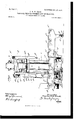
- Figure 1 is a front elevacarrier is provided at its end adjacent the tion of the machine, parts being broken away saw with 'a guiding-surface, herein shown as 8 5 5 and shown in section for clearness of undera dovetail arm h, on which is mounted a standing.
- Fig. 2 is a transverse horizontal shield 79, which incloses the saw or other tool section thereof, taken on theline 2, Fig. 1, said to such a degree as may be required or adfigure showing the table in top plan view. Fig. visable, according to the situation.
- Prefer- 3 is a detail view showing in top plan the ably, also, the shield is provided with a coun- 9o 40 shield-carrier and the adjacent parts in secterbalance-arm h extending rearwardly, and tion.
- Fig. i is a side elevation viewing Fig. an adjustable weight h to compensate for 1 from the right.
- any forward or rearward adjustment of the Extending from a suitable base A is a vertishield to suit difierent sizes of saws which cal column B and a bed C.
- the column at its may be used, the shield being held in adjust- 9 5 front face is provided with opposite guides a, ment by any suitable means, as by a setherein shown as projecting laterally away screw h from each other, to provide guide flanges
- the tool-carrier D may slide, as evident that when the saw and shield descend clearly shown in Figs. 1 and 4. to the work the shield upon coming in con- 100
- the bed C consists of a stationary part c tact therewith simply stops and the saw conand a movable part c, the latter being capatinues to descend as the operator may require.
- the feeding of the saw up and down may be accomplished in any convenient mannor, a reversible screw 8 being herein shown as provided for that purpose, working in a nut s on the rear side of the tool-carrier D and carried by a wheel s on the column, be ing driven by a bevel-gear s on a shaft 8 containing reversing-pulleys s s, the latter being shown as a step-pulley forgiving downward movement at diiferentdegrees of speed.
- pulleys are driven by belts 8 5 passing over corresponding pulleys e e on the drive-shaft e
- These pulleys cooperate with usual clutch mechanism (2 e on a longitudinallymovable shaft e reciprocated by a bell-crank e connected by a link e with a foot-lever 8, moving in opposition to a spring 6 on the shaft o
- an automatic reversing and stopping rod e provided with a reversing-block e and a stop-block e to be engaged by a lug d of the carrier D, traveling over said rod.
- the table is provided with fences or gages c c c and feed-rolls 0 in usual manner.
- the table When the table is to be used in astraight line, it is placed as shown in full lines in Fig. 2; but when the movable part is to be swung around at an angle to the stationary part the pin 0 is withdrawn from engaging with the bracket 0 and the table 0 is then shoved straight back until the pin 0 drops into a second pivot-hole 0", thereby carrying the center of movement of the movable table back correspondingly, so that the timber will approach the saw relatively to the center of the latter as nearly as possible in the same relation as it did when the table was in its other adjustment.
- a further ad vantage of the provision of a stationary part and a swinging part of the table is of special importance in connection with this same class of timbers, which, as is well known, are very seldom required to be cut square across at both ends, but are usually cut with one end square and the opposite end beveledas, for instance, in car braces. This can be accomplished by my invention without requiring an alteration of the table, inasmuch as the timber can simply be fed in from the right-hand end of the machine, and
- the table is first adjusted to the exact requirements of the work, and then, 'the timber having been fed to position, the operator depresses the treadle, whereupon the saw and shield descend, the latter engaging the work and remaining on top thereof, while the saw descends to the depth required by the reversing-block e and when the carrier D meets the latter it automatically reverses the saw, carrying the same into its upper position, where it stops.
- the shield-carrier H simply stops or halts on the guides, while the saw-carrierD continues to move down farther along the latter. If a larger or smaller saw or other tool is required, the shield is moved out or in, as required, simply by loosening the set-screw 72, and shoving it along the guide-arm h.
- a machine of the kind described for handling heavy timber comprising a work-support, a tool-carrier movable up and down relatively thereto, a circular saw carried thereby, a shield inclosing the top and front edge entire vertical length of the latter, and said shield being freely movable toward and from said saw independently of the latter, the shield preventing the operator from being able to come in contact with the saw.
- a machine of the kind described for hantimbers comprising a Work support or table, a tool and tool-carrier movable up and down relatively thereto, said table having a stationary part for supporting the timbers, and a movable part for supporting the timbers, the supporting-surfaces of both of said parts beingin the same horizontal plane, and means for horizontally adjusting the latter part obliquely to the former part without interfering with the proper action of said tool.
- a machine of the kind described for handlin g heavy timbers comprising a table made of a movable supporting part and a stationary supporting part, a saw and saw-carrier movable vertically above said stationary part for cutting said timbers transversely thereof, said movable part being movable obliquely to said stationary part, and provided with means for shifting the rear pivotal end of said mov able'part next to the saw backward toward the center line of the saw for gaining saw distance.
- a machine of the kind described for handling heavy timbers comprising a work-support, a tool-carrier movable up and down relatively thereto, a tool carried thereby, a shield for said tool, said shield extending the vertical length of said tool and embracing the exposed front portion of said tool for said entire length, means for permitting said shield to halt at the work while the tool penetrates the latter, and means for adjusting said shield in and out transversely of the direction of movement of the tool.
- a machine of the kind described for handling heavy timbers comprising a work-support, a vertical guide, a tool and tool-carrier mounted to slide thereon, a shield and shieldcarrier also mounted to slide thereon, and resting freely on said tool-carrier, whereby when the shield contacts with the work, it automatically stops and permits the tool to continue forward.
- a machine of the kind described for handling heavy timbers comprising a horizontal work-table composed of two parts pivotally connected, one of said parts being stationary, and the other part capable of swinging in a horizontal plane, each of said parts being provided with a supporting-surface consisting of transverse feed-rolls, gages cooperating with said feed-rolls, and a tool and tool-carrier movable vertically above said stationary part, adjacent said movable part.
- a machine of the kind described for handling heavy timbers comprising a tool and tool-carrier movable vertically, a work-support composed of a stationary part having transverse feed-rolls for receiving the timber, a movable part also having transverse feed-rolls for receiving a timber, a track adj acent the outer end of said movable part, said movable part having a leg resting on the track, means for clamping the same in adjustment on said track, and means pivotally connecting the inner ends of said movable part and stationary part.
- a machine of the kind described for handling heavy timbers comprising a work-table, a tool and tool carrier movable vertically above said table, said table comprising a stationary part provided at one end with a horizontal ledge, a movable part adapted at its inner end to rest on said ledge, said movable part when so resting having its upper surface on a horizontal level with the upper surface of said stationary part, means permitting said movable part to swing horizontally with relation to said stationary part, and two pivotal connections for said movable part, said movable part being shiftable from one to the other, said tool being located above the end of the stationary part next to the movable part.
Landscapes
- Engineering & Computer Science (AREA)
- Mechanical Engineering (AREA)
- Chemical & Material Sciences (AREA)
- Organic Chemistry (AREA)
- Sawing (AREA)
Description
' No. 742,772. PATBNTED 001. 27, 1903,
C. W. H. BLOOD.
VERTICAL FEED TR ANSVERSE CUTTING MACHINE.
APPLICATION TILED HEP T. 12, 1902. N0 MODEL.
3 SHEETS-SHEET 1- w: NORRIS Prm'ws co. Pno'rou'mo" wAs-mm'ov. n. c.
No. 742,772. '4 V PATENTBDVOOT. 27, 1903.
. v c. w. H. BLOOD. VERTICAL FEED TRANSVERSE CUTTING MACHINE.
APPLICATION FILED SEPT. 12, 1902. no MODEL.
3 SHEETS-8111212112.
wpfimeai lwewoan No. 742,772. I PATENTED' OCT. 7, 1903; 0. W. H.. BLOOD.
I VERTICAL FEED TRANSVERSE CUTTING MACHINE.
APPLIOATION FILED SEPT. 12, 1902. v no MODEL. 7 s Bums-mum a.
i M I 0 22% 4 TNE uunms vzrzas co. moruunn. wnsnma'mu. a c.
so. 742,772. rammed October 27, 1902 UNITED STATES PATENT -OFFICE.
CHARLES W. H. BLOOD, OF BOSTON, MASSACHUSETTS, ASSIGNOR TO S. A. WOODS MACHINE COMPANY, OF BOSTON, MASSACHUSETTS.
VERTICAL-FEED TRANSVERSE CUTTlNG MACHINE.
SPECIFICATION forming part of Letters Patent No. 742,772, dated October 27, 1903.
Application filed September 12,1902. Serial No. 123,069. (No model.)
To all whom it may concern: ble of moving in an arc, herein shown as di- Be it known that I, CHARLES W. H. BLOOD, rected by a track and as pivoted or hinged a citizen of the United States, and a resident on a pivot-pin c to the stationary part c, the of Boston, county of Suffolk, State of Massaouter or swinging end of the movable part c 5 chusetts, have invented an Improvement in being provided with a leg 0 resting on the Vertical-Feed Transverse-Cutting Machines, track 0 and adapted to be clamped rigidly in of which the following description, in connecany adjustment by a locking device or clamp tion with the accompanying drawings, is a 0 The inner end of the movable part c is specification,like letters on the drawings repherein shown as supported on a ledge or 60 to resenting like parts. bracket 0 extending from the adjacent end My invention is a machine for severing or of the stationary part c. Adjacent thereto cutting across or into timbers, and is particthe stationary part is provided with a vertiularly intended for handling heavy timbers, cal chamber or channel 0 to receive the tool, the construction being such that the saw or which is herein shown as a circular saw d, 65 tool approaches the timber from the top, the mounted on the end of an arbor d, journaled saw meanwhile being guarded by a shield at d in the tool-carrier D and driven by a and the latter remaining on top of the timber belt 6, passing under a pulley c on said aras the saw enters and descends into the latbor d and over an idler 6 also mounted on ter, said shield being carried up by the saw or the tool-carrier D, and thence passing down- 70 2o saw-carrying frame as the latter moves away wardly over a driving-pulley e mounted on from the timber after having done its work. the drive-shaft e, and up over a binder-pul- Also my invention provides means for enley a, mounted on the top of the column B, abling the timber to be out square at one end said binder-pulley being pivoted in usual and beveled or oblique at the other end withmanner onthe projecting ends of counterbal- 75 z 5 out changing the adjustment of the table. ance-levers e for maintaining the belt taut. Various other features of invention and ad- Mounted in any suitable manner to be cavantages thereof are embodied in the ma' pable of movement independent of the toolchine and will be pointed out more fully in carrier D is a shield-carrier H, herein shown the course of the following description, ref- (see particularly Fig. 3) as providedwith 8o erence being bad to the accompanying drawarms h, embracing the guideways a and restings, illustrative of one embodiment of my ing directly on top of the tool-carrier and invention. carrying the same by gravity. This shield- In the drawings, Figure 1 is a front elevacarrier is provided at its end adjacent the tion of the machine, parts being broken away saw with 'a guiding-surface, herein shown as 8 5 5 and shown in section for clearness of undera dovetail arm h, on which is mounted a standing. Fig. 2 is a transverse horizontal shield 79, which incloses the saw or other tool section thereof, taken on theline 2, Fig. 1, said to such a degree as may be required or adfigure showing the table in top plan view. Fig. visable, according to the situation. Prefer- 3 is a detail view showing in top plan the ably, also, the shield is provided with a coun- 9o 40 shield-carrier and the adjacent parts in secterbalance-arm h extending rearwardly, and tion. Fig. i is a side elevation viewing Fig. an adjustable weight h to compensate for 1 from the right. any forward or rearward adjustment of the Extending from a suitable base A is a vertishield to suit difierent sizes of saws which cal column B and a bed C. The column at its may be used, the shield being held in adjust- 9 5 front face is provided with opposite guides a, ment by any suitable means, as by a setherein shown as projecting laterally away screw h from each other, to provide guide flanges From the foregoing description it will be along which the tool-carrier D may slide, as evident that when the saw and shield descend clearly shown in Figs. 1 and 4. to the work the shield upon coming in con- 100 The bed C consists of a stationary part c tact therewith simply stops and the saw conand a movable part c, the latter being capatinues to descend as the operator may require. The feeding of the saw up and down may be accomplished in any convenient mannor, a reversible screw 8 being herein shown as provided for that purpose, working in a nut s on the rear side of the tool-carrier D and carried by a wheel s on the column, be ing driven by a bevel-gear s on a shaft 8 containing reversing-pulleys s s, the latter being shown as a step-pulley forgiving downward movement at diiferentdegrees of speed. These pulleys are driven by belts 8 5 passing over corresponding pulleys e e on the drive-shaft e These pulleys cooperate with usual clutch mechanism (2 e on a longitudinallymovable shaft e reciprocated by a bell-crank e connected by a link e with a foot-lever 8, moving in opposition to a spring 6 on the shaft o Also connected with said link e by a bell-crank e is an automatic reversing and stopping rod e provided with a reversing-block e and a stop-block e to be engaged by a lug d of the carrier D, traveling over said rod.
The table is provided with fences or gages c c c and feed-rolls 0 in usual manner. When the table is to be used in astraight line, it is placed as shown in full lines in Fig. 2; but when the movable part is to be swung around at an angle to the stationary part the pin 0 is withdrawn from engaging with the bracket 0 and the table 0 is then shoved straight back until the pin 0 drops into a second pivot-hole 0", thereby carrying the center of movement of the movable table back correspondingly, so that the timber will approach the saw relatively to the center of the latter as nearly as possible in the same relation as it did when the table was in its other adjustment. In other words, by moving the pivot back to the hole 0 I gain saw distance, which is of considerable importance in treating heavy timbers, because such timbers being large require a large saw, and hence when a timber is being sawed obliquely itis evident that if the pivot-point were not shifted back as shown in Fig. 2 the projecting end of the timber would be carried forward unduly, and hence would require a much larger saw, greater power, and a heavier-machine, whereas by moving the pivot-point back the timber is caused to meet the saw as nearly in vertical alinement with the center as is possible. A further ad vantage of the provision of a stationary part and a swinging part of the table is of special importance in connection with this same class of timbers, which, as is well known, are very seldom required to be cut square across at both ends, but are usually cut with one end square and the opposite end beveledas, for instance, in car braces. This can be accomplished by my invention without requiring an alteration of the table, inasmuch as the timber can simply be fed in from the right-hand end of the machine, and
when the advance end is in proper position beneath the saw the bevel cut is made, and
what I claim, and desire Patent, is-
of said saw for the dling heavy then the timberis simply fed along onto the stationary part 0 until the rear end of the timber comes to proper position, when the square cut is made, the two gages a 0 (and 0 being in proper relation to the saw for accomplishing this result.
In operation the table is first adjusted to the exact requirements of the work, and then, 'the timber having been fed to position, the operator depresses the treadle, whereupon the saw and shield descend, the latter engaging the work and remaining on top thereof, while the saw descends to the depth required by the reversing-block e and when the carrier D meets the latter it automatically reverses the saw, carrying the same into its upper position, where it stops. When the shield first engages the timber, the shield-carrier H simply stops or halts on the guides, while the saw-carrierD continues to move down farther along the latter. If a larger or smaller saw or other tool is required, the shield is moved out or in, as required, simply by loosening the set-screw 72, and shoving it along the guide-arm h.
By the termsawIdo not mean to re strict myself to a circular saw, but mean to include any transversely-cutting tool.
Without undertaking to set forth all the advantages of my invention and the arrangements and modifications of parts which are within the spirit and scope of my invention, to secure by Letters 1. A machine of the kind described for handling heavy timber, comprising a work-support, a tool-carrier movable up and down relatively thereto, a circular saw carried thereby, a shield inclosing the top and front edge entire vertical length of the latter, and said shield being freely movable toward and from said saw independently of the latter, the shield preventing the operator from being able to come in contact with the saw.
2. A machine of the kind described for hantimbers, comprising a Work support or table, a tool and tool-carrier movable up and down relatively thereto, said table having a stationary part for supporting the timbers, and a movable part for supporting the timbers, the supporting-surfaces of both of said parts beingin the same horizontal plane, and means for horizontally adjusting the latter part obliquely to the former part without interfering with the proper action of said tool.
3. A machine of the kind described for handlin g heavy timbers, comprising a table made of a movable supporting part and a stationary supporting part, a saw and saw-carrier movable vertically above said stationary part for cutting said timbers transversely thereof, said movable part being movable obliquely to said stationary part, and provided with means for shifting the rear pivotal end of said mov able'part next to the saw backward toward the center line of the saw for gaining saw distance. I
4. A machine of the kind described for handling heavy timbers, comprising a work-support, a tool-carrier movable up and down relatively thereto, a tool carried thereby, a shield for said tool, said shield extending the vertical length of said tool and embracing the exposed front portion of said tool for said entire length, means for permitting said shield to halt at the work while the tool penetrates the latter, and means for adjusting said shield in and out transversely of the direction of movement of the tool.
5.v A machine of the kind described for handling heavy timbers, comprising a work-support, a vertical guide, a tool and tool-carrier mounted to slide thereon, a shield and shieldcarrier also mounted to slide thereon, and resting freely on said tool-carrier, whereby when the shield contacts with the work, it automatically stops and permits the tool to continue forward.
6. A machine of the kind described for handling heavy timbers, comprising a horizontal work-table composed of two parts pivotally connected, one of said parts being stationary, and the other part capable of swinging in a horizontal plane, each of said parts being provided with a supporting-surface consisting of transverse feed-rolls, gages cooperating with said feed-rolls, and a tool and tool-carrier movable vertically above said stationary part, adjacent said movable part.
7. A machine of the kind described for handling heavy timbers, comprising a tool and tool-carrier movable vertically, a work-support composed of a stationary part having transverse feed-rolls for receiving the timber, a movable part also having transverse feed-rolls for receiving a timber, a track adj acent the outer end of said movable part, said movable part having a leg resting on the track, means for clamping the same in adjustment on said track, and means pivotally connecting the inner ends of said movable part and stationary part.
8. A machine of the kind described for handling heavy timbers, comprising a work-table, a tool and tool carrier movable vertically above said table, said table comprising a stationary part provided at one end with a horizontal ledge, a movable part adapted at its inner end to rest on said ledge, said movable part when so resting having its upper surface on a horizontal level with the upper surface of said stationary part, means permitting said movable part to swing horizontally with relation to said stationary part, and two pivotal connections for said movable part, said movable part being shiftable from one to the other, said tool being located above the end of the stationary part next to the movable part.
In testimony whereof I have signed my name to this specification in the presence of two subscribing witnesses.
CHARLES W. H. BLOOD.
Witnesses:
F. A. CHENEY, R. S. OROSSKILL.
Priority Applications (1)
| Application Number | Priority Date | Filing Date | Title |
|---|---|---|---|
| US1902123069 US742772A (en) | 1902-09-12 | 1902-09-12 | Vertical-feed transverse-cutting machine. |
Applications Claiming Priority (1)
| Application Number | Priority Date | Filing Date | Title |
|---|---|---|---|
| US1902123069 US742772A (en) | 1902-09-12 | 1902-09-12 | Vertical-feed transverse-cutting machine. |
Publications (1)
| Publication Number | Publication Date |
|---|---|
| US742772A true US742772A (en) | 1903-10-27 |
Family
ID=2811270
Family Applications (1)
| Application Number | Title | Priority Date | Filing Date |
|---|---|---|---|
| US1902123069 Expired - Lifetime US742772A (en) | 1902-09-12 | 1902-09-12 | Vertical-feed transverse-cutting machine. |
Country Status (1)
| Country | Link |
|---|---|
| US (1) | US742772A (en) |
Cited By (1)
| Publication number | Priority date | Publication date | Assignee | Title |
|---|---|---|---|---|
| US3313193A (en) * | 1964-04-20 | 1967-04-11 | Wagner Maschf Gustav | Circular saw with a vertical tool feed |
-
1902
- 1902-09-12 US US1902123069 patent/US742772A/en not_active Expired - Lifetime
Cited By (1)
| Publication number | Priority date | Publication date | Assignee | Title |
|---|---|---|---|---|
| US3313193A (en) * | 1964-04-20 | 1967-04-11 | Wagner Maschf Gustav | Circular saw with a vertical tool feed |
Similar Documents
| Publication | Publication Date | Title |
|---|---|---|
| US742772A (en) | Vertical-feed transverse-cutting machine. | |
| US1241871A (en) | Self-feed sawing-machine. | |
| US1920584A (en) | Sawing of logs | |
| US1359394A (en) | Intermittent and oscillatory rotary cut-off saw-machine | |
| US784409A (en) | Wood-sawing machine. | |
| US582195A (en) | Machine for working wood or metal | |
| US578826A (en) | Sawing-machine | |
| US290327A (en) | Sawing and gaining machine | |
| US1098465A (en) | Mitering-machine. | |
| US283341A (en) | greenlee | |
| US273000A (en) | Feed-table gage for curved work | |
| US487637A (en) | Wood turning and working machine | |
| US529839A (en) | Sawing-machine | |
| US358003A (en) | X x x a a | |
| US516677A (en) | Automatic feed for band sawing-machines | |
| US236120A (en) | Machine for trimming boxes | |
| US621026A (en) | brown | |
| US476202A (en) | Sash-machine | |
| US799837A (en) | Gang cut-off sawing-machine. | |
| US256464A (en) | Machine for sawing and grooving shakes | |
| US650820A (en) | Tenoning-machine. | |
| US1234015A (en) | Woodworking-machine. | |
| US784348A (en) | Handhold-sawing machine. | |
| US1072691A (en) | Wood-planing- machine | |
| US1154752A (en) | Routing-machine. |