US7321699B2 - Signal intensity range transformation apparatus and method - Google Patents
Signal intensity range transformation apparatus and method Download PDFInfo
- Publication number
- US7321699B2 US7321699B2 US10/657,723 US65772303A US7321699B2 US 7321699 B2 US7321699 B2 US 7321699B2 US 65772303 A US65772303 A US 65772303A US 7321699 B2 US7321699 B2 US 7321699B2
- Authority
- US
- United States
- Prior art keywords
- grey
- image
- levels
- output
- cumulative distribution
- Prior art date
- Legal status (The legal status is an assumption and is not a legal conclusion. Google has not performed a legal analysis and makes no representation as to the accuracy of the status listed.)
- Expired - Fee Related, expires
Links
Images


Classifications
-
- G—PHYSICS
- G06—COMPUTING; CALCULATING OR COUNTING
- G06T—IMAGE DATA PROCESSING OR GENERATION, IN GENERAL
- G06T5/00—Image enhancement or restoration
- G06T5/70—Denoising; Smoothing
-
- G—PHYSICS
- G06—COMPUTING; CALCULATING OR COUNTING
- G06T—IMAGE DATA PROCESSING OR GENERATION, IN GENERAL
- G06T5/00—Image enhancement or restoration
- G06T5/40—Image enhancement or restoration using histogram techniques
-
- G—PHYSICS
- G06—COMPUTING; CALCULATING OR COUNTING
- G06T—IMAGE DATA PROCESSING OR GENERATION, IN GENERAL
- G06T5/00—Image enhancement or restoration
- G06T5/90—Dynamic range modification of images or parts thereof
- G06T5/94—Dynamic range modification of images or parts thereof based on local image properties, e.g. for local contrast enhancement
-
- H—ELECTRICITY
- H04—ELECTRIC COMMUNICATION TECHNIQUE
- H04N—PICTORIAL COMMUNICATION, e.g. TELEVISION
- H04N23/00—Cameras or camera modules comprising electronic image sensors; Control thereof
- H04N23/80—Camera processing pipelines; Components thereof
- H04N23/84—Camera processing pipelines; Components thereof for processing colour signals
-
- H—ELECTRICITY
- H04—ELECTRIC COMMUNICATION TECHNIQUE
- H04N—PICTORIAL COMMUNICATION, e.g. TELEVISION
- H04N5/00—Details of television systems
- H04N5/14—Picture signal circuitry for video frequency region
- H04N5/20—Circuitry for controlling amplitude response
-
- G—PHYSICS
- G06—COMPUTING; CALCULATING OR COUNTING
- G06T—IMAGE DATA PROCESSING OR GENERATION, IN GENERAL
- G06T2207/00—Indexing scheme for image analysis or image enhancement
- G06T2207/10—Image acquisition modality
- G06T2207/10016—Video; Image sequence
-
- G—PHYSICS
- G06—COMPUTING; CALCULATING OR COUNTING
- G06T—IMAGE DATA PROCESSING OR GENERATION, IN GENERAL
- G06T2207/00—Indexing scheme for image analysis or image enhancement
- G06T2207/20—Special algorithmic details
- G06T2207/20024—Filtering details
- G06T2207/20032—Median filtering
Definitions
- the present invention generally relates to imaging systems, and in particular, to a system for manipulating image data.
- Extreme lighting variation for example, due to sunlight beams, can cause typical video cameras and imaging sensors to saturate (i.e., become unable to represent the real-world luminance range) resulting in wide-scale bright and dark regions having extremely low-contrast wherein objects are difficult or impossible to discern.
- sunlight beams or strong lighting in the background can cause a person in a dark area to become unidentifiable due to low contrast. This weakness is due to the limited luminance range of the imaging system.
- the electronic iris and automatic gain control provided by some imaging systems are designed to try to optimally map the wide luminance values within a real-world light situation into a limited range digital representation, often resulting in a poor compromise. To adequately represent the bright areas, less illuminated areas become dramatically compressed in contrast and thus become very dark.
- video or imagery from lower-cost imaging sensors can have significant noise due to a number of basic system limitations, as well as significant blur due to lower-cost, small, or simple optical configurations. Reducing noise and blur within these systems can improve the ability for a human viewer to effectively interpret image content.
- a system and method has been developed that considers the mechanisms and defects of imagery from video or other sources to prescribe a sequence of tailored image processing operations designed to improve human interpretation of resulting images.
- the detailed disclosures below are directed to redistribution of grey-scale or luminance values in a rectilinear array (pixels) from a camera. It is also contemplated however, that the inventions may be applied to other values in a video image, such as redistribution of chrominance values. It is also proposed that the inventions may be employed with other sensing modalities such as, magnetic resonance imagery, radar, sonar, infrared, ultraviolet, microwave, X-ray, radio wave, and the like.
- the spatial scale of an entire group of signal intensity values are considered, for example, the luminance in an entire pixel image, so that the overall brightness from corner to corner is taken into account.
- all the frequency content of an image must be represented by the one global mapping, including the very lowest spatial frequency.
- this single global mapping has to stretch to map all of the low frequency variation in the image, and then fails to enhance higher frequency structure of interest. The result can be a bright “bloom” on one side of the image, with too dark an area on the other side of the image. As such, there may not be optimal recognition of spatial structure because of the need to represent the large scale variation across the entire image.
- the inventions propose generating subset partitions of an image (group of signal intensities) representative of the spatial scales of interest.
- a transform mapping e.g. of luminance
- a spatial scale e.g., is 1 ⁇ 4 of a global image for a quadrant subset
- the present invention employs accumulating pixel samples across larger “right-sized” spatial scales, while using efficient interpolation to produce the correct transform (e.g. for luminance) representation at each pixel.
- apparatus and methods include: decomposing a group of signal values into subgroup partitions from which to sample values and construct associated transforms and to combine those transform values at every coordinate (e.g. pixel) according to a rule which weights the contribution of each mapping in accordance with “image” geometry and value coordinate or position.
- apparatus and methods are provided for blending transformed values from the global set of values (e.g. entire pixel image) with transformed values from the spatial segments to adjust contributions from several spatial scales as desired.
- preferred operations can include digital sampling and luminance/color separation, noise reduction, deblurring, pixel noise reduction, histogram smoothing, contrast stretching, and luminance and chrominance re-combination.
- One or more of the operators can have configurable attributes, such as degree of noise reduction, brightness, degree of deblurring, and determined range of useful grey-levels.
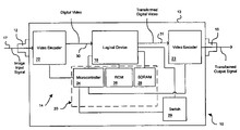
- FIG. 1 is a simplified block diagram of a device in accordance with the present invention, including a logical device;
- FIG. 2 is a simplified functional block diagram of a process performed by the logical device of FIG. 1 , the process having a color transform, an image pre-contrast conditioner, a contrast enhancement, an image post-contrast conditioner, and a color inverse transform;
- FIG. 3 is a simplified functional block diagram of the image pre-contrast conditioner of FIG. 2 , the pre-contrast conditioner comprising a system noise reduction filter, a deblurring module, and a pixel noise reduction module;
- FIGS. 4( a )-( f ) depict various exemplary kernels shapes that can be used with the system noise reduction filter, deblurring module, and pixel noise reduction module of FIG. 3 ;
- FIG. 5 is a simplified functional block diagram of the contrast enhancement block of FIG. 2 , the contrast enhancement comprising an equalized lookup table construction block and an enhanced luminance image generation block;
- FIG. 6 is a simplified functional block diagram of the equalized lookup table construction block of FIG. 5 ;
- FIG. 7 is a simplified functional block diagram of another embodiment of the contrast enhancement block of FIG. 2 ;
- FIGS. 8 and 9 is a simplified function block diagram of yet another embodiment of the contrast enhancement block of FIG. 2 .
- each of the FIGURES depicts a simplified block diagram wherein each block provides hardware (i.e., circuitry), firmware, software, or any combination thereof that performs one or more operations.
- hardware i.e., circuitry
- firmware software
- Each block can be self-contained or integral with other hardware, firmware, or software associated with one or more other blocks.
- a device 10 for enhancing, through transformation, the luminance range of an image input signal.
- the device 10 includes an input connector 12 , logic circuitry 14 , and an output connector 16 .
- the connectors 12 and 16 are mounted in a conventional manner to an enclosed housing 13 , constructed of a metal, metal alloy, rigid plastic, or combinations of the above, that contains the logic circuitry 14 .
- one or more of the modules described herein are performed by the logic circuitry 14 comprising of one or more integrated circuits, commonly referred to as “ICs,” placed on one or more printed circuit boards mounted within the housing 13 .
- ICs integrated circuits
- the device 10 is a stand-alone or embedded system.
- the term “stand-alone” refers to a device that is self-contained, one that does not require any other devices to perform its primary functions.
- a fax machine is a stand-alone device because it does not require a computer, printer, modem, or other device.
- the device 10 does not need to provide ports for connecting a disk drive, display screen, or a keyboard.
- the device 10 could provide one or more ports (e.g., RS-232) for supporting field interactivity.
- an embedded system is a system that is not a desktop computer or a workstation computer or a mainframe computer designed to admit facile human interactivity.
- Another delineator between embedded and “desktop” systems is that desktop systems (and workstation, etc.) present the status of the computer state to the human operator via a display screen and the internal state of the computer is represented by icons on the screen, and thus the person can interact with the computer internal state via control of the icons.
- desktop systems and workstation, etc.
- Such a computer uses a software layer called an “operating system” through which the human operator can interact with the internal state of the computer.
- an embedded system while it is performing its work function, the human operator cannot interact with the work process except to stop it.
- the input connector 12 provides for operably connecting the device 10 to an image input signal 17 generated by a video camera (not shown), or the like, having a video output.
- the input connector 12 consists of an F connector, BNC connector, RCA jacks, or the like.
- the input connector 12 is operably connected to the logic circuitry 14 by way of a conductive path attached to the input connector and the printed circuit board contained within the housing 13 .
- the logic circuitry could also be coupled through other than a conductive path such as through optical coupling.
- the image input signal 17 is a conventional analog video signal containing a plurality of still images or fixed image frames taken in a sequential manner.
- Each frame provided by the image input signal is also referred to herein as an image input frame.
- Each image or frame includes data regarding an array of pixels contained therein.
- the output connector 16 of the device 10 provides for connecting the device to an output device such as a monitor (not shown). Like the input connector 12 , the output connector 16 consists of any means for outputting the signal to other devices such as, an F connector, BNC connector, RCA jacks, or the like.
- the output connector 16 is operably connected to the logic circuitry 14 by way of a conductive or coupled path attached to the output connector and the printed circuit board contained within the housing 13 .
- the output signal provided by connector 16 and thus the device 10 , provides an output signal which includes data resulting from transforming or other operations carried out with respect to image input signal 17 received (“transformed output signal”).
- the output signal can include a plurality of image output frames and be formatted as a conventional analog video signal, a digital signal, or the like.
- the output signal can be in a format as defined by NTSC, VGA, HDTV, or other desired output formats.
- the logic circuitry 14 within the device 10 includes, inter alia, circuitry configured to transform the variable range of grey-scale values in the image input signal 17 received by the input connector 12 .
- the logic circuitry 14 includes a logical device 18 with corresponding support circuitry 20 , a video decoder 22 , and a video encoder 23 .
- the support circuitry 20 preferably includes a microcontroller 24 , a read only memory 26 , and a random access memory 28 comprising a synchronous dynamic random access memory.
- an optional switch 29 is provided for configuring the logic circuitry 14 within the device 10 .
- the switch 29 is operably connected to the microcontroller 24 and logical device 18 .
- the switch 29 allows a user to enable or disable, features or processes provided by the logic circuitry 14 within the device 10 .
- the switch 29 consists of a conventional DIP switch.
- the configuration of the circuitry 14 within the device 10 is hardwired, or can be set via software commands, instead of using a switch.
- video decoder 22 is operably connected to the input connector 12 and the logical device 18 . Accordingly, the video decoder 22 receives the image input signal 17 that can consist of live video from a television broadcast, a video tape, a camera, or any other desired signals containing or representing image content.
- the video decoder 22 preferably is a conventional device for tracking the video image input signal 17 , digitizing the input signal (if required), separating out the brightness and color information from the input signal, and forwarding the digital video signal 30 to the logical device 18 on a frame by frame basis.
- the input image signal 17 received by the video decoder 22 is an analog signal formatted in a predefined manner such as PAL, NTSC, or another conventional format.
- the video decoder 22 converts the analog signal 17 into a digital video signal 30 using a conventional analog-to-digital conversion algorithm.
- the digital video signal 30 provided by the video decoder 22 includes luminance information and color information in any conventional manner such as, specified by YUV format, YCbCr format, super video, S-video, or the like.
- the digital video signal 30 can have the luminance information embedded therein such as that provided by digital RGB, for example.
- the video decoder 22 is capable of converting a plurality of different analog video formats into digital video signals suitable for processing by the logical device 18 as described in detail further herein.
- the microcontroller 24 configures the video decoder 22 for converting the image input signal 17 into a digital video signal 30 having a specific format type (e.g., CCIR601, RGB, etc.). If desired, the microcontroller 24 determines the format of the image input signal 17 , and configures the video decoder 22 accordingly. The determination can be accomplished by the microcontroller 24 checking the user or device manufacturer configured settings of the DIP switch corresponding with the format of the image input signal 17 expected to be received. Alternatively, the video decoder 22 can include circuitry for automatically detecting the format of the image input signal 17 , instead of using preset DIP switch settings.
- the gain of the video decoder 22 is set to reduce overall contrast on the luminance for reducing the probability of image saturation.
- the video decoder 22 provides a fixed bit resolution output range (e.g., 8 bit, 16 bit, 32 bit, etc.) and a digitizer maps the image input signal in a conventional manner for effective use of the resolution output range.
- the full range of the digitizer output is utilized.
- the logical device 18 receives digital video signals 30 and provides digital output signals 31 (i.e., transformed pixel array or frame data) in response to the digital video signals 30 .
- the device 10 receives analog image input signals 17 that are converted by the video decoder 22 into digital video signals 30 for manipulation by the logical device 18 .
- the digital output 31 of the logical device 18 can be converted (if desired) into an analog output by the video encoder 23 connected between the logical device 18 and the output connector 16 .
- the logical device 18 consists of a conventional field programmable gate array (FPGA).
- the logical device 18 can consists of a Digital Signal Processor (DSP), a microcontroller, an Application Specific Integrated Circuit (ASIC), or other suitable device.
- DSP Digital Signal Processor
- ASIC Application Specific Integrated Circuit
- the device 10 instead of receiving analog input signals 17 , the device 10 can receive digital image input signals that are provided, without any conversion, to the logical device 18 .
- the video decoder 22 can be omitted.
- the logical device 18 is operably connected between connectors 12 and 16 . Accordingly, an image input signal enters the input connector 12 , is modified by the logical device 18 , and then exits via the output connector 16 as a transformed output signal.
- the frame output rate of the device 10 is substantially equal to the frame input rate to the device.
- the device 10 provides an output of thirty frames per second in response to a frame input rate of thirty frames per second.
- the logical device 18 provides a sequence of image processing functional modules or blocks 32 within a process as illustrated in FIG. 2 .
- the blocks 32 represent a color transform 34 , an image pre-contrast conditioner 36 , a contrast enhancement 38 , an image post-contrast conditioner 40 , and a color inverse transform 42 .
- Each of the modules 32 preferably performs a specific functional step or plurality of functional steps as described in detail further herein.
- static data for configuring the logical device 18 is stored within the read only memory 26 operably connected thereto.
- the read only memory 26 provides for storing data that is not alterable by computer instructions.
- SDRAM synchronous dynamic random access memory
- a high speed random access memory is provided by the support circuitry 20 to reduce performance bottlenecks.
- the memory 20 is used as a field buffer.
- the color transform 34 provides for separating the luminance from the digital video signal 30 , as desired.
- the digital video signal 30 provided by the video decoder 22 consists of a digital RGB signal.
- luminance information is not separated from color information.
- the color transform 34 provides for separating the luminance information for each pixel, within each frame, from the digital video signal 30 .
- the color transform 34 uses a conventional algorithm for converting a digital RGB video input signal into a Yuv format signal, YCbCr format signal, or other desired format signal. Accordingly, the color transform 34 provides an output comprising three channels: luminance 43 , and U-V or other values ascribed per pixel location.
- the digital video signal 30 provided by the video decoder 22 consists of a super video or S-video.
- the digital video signal 30 consists of two different signals: chrominance and luminance. Accordingly, the color transform 34 can be omitted from the process of FIG. 2 because the luminance 43 is separately provided by the S-video input.
- a separate channel or channels comprising the steps to be discussed below with respect to luminance information, could be provided to any one of RGB/chrominance values independently for transforming the values and redistributing the color values in the image.
- the luminance information 43 contained within the digital video signal 30 is received by the image pre-contrast conditioner 36 .
- the image pre-contrast conditioner 36 can include a video time integration module or block 44 , a system noise reduction module or block 46 , a deblurring module or block 48 , and a pixel noise reduction module or block 50 .
- any one or all of the blocks within FIG. 3 can be omitted including, but not limited to, the video time integration module 44 .
- the video time integration module 44 consists of a low-pass filter for noise reduction of the luminance signal 43 .
- each frame includes an array of pixels wherein each pixel has a specific i,j coordinate or address.
- Noise reduction by the video time integration module 44 is preferably achieved by combining the current frame (n) with the immediately preceding frame (n- 1 ) stored by the logical device 18 within the memory 28 .
- the corresponding pixel p(i,j) from the preceding captured frame (n- 1 ) is subtracted to result in a difference d(i,j).
- the absolute value of the difference d(i,j) is determined, and compared to a predetermined threshold value. If the absolute value of the difference d(i,j) is greater than the predetermined threshold, then the time integration output signal 45 of the video time integration module 44 is c(i,j). Otherwise, the time integration output signal 45 of the video time integration module 44 is the average of c(i,j) and p(i,j).
- the video time integration module 44 can operate such that object motion, which ordinarily creates large pixel differences, are represented by current pixels while background differences due to noise are suppressed by the averaging. Accordingly, the video time integration module 44 provides for avoiding image blurring as a result of low-pass spatial domain filtering on the current image.
- the median filter or system noise reduction module 46 receives the time integration output signal 45 (i.e., transformed pixel frame data) and, in response thereto, provides for reducing pixel noise caused by the system senor (e.g., camera), electromagnetic, and/or thermal noise.
- the median filter 46 can include a user selectable level of noise reduction by selecting from a plurality of filter kernels via DIP switch 29 , or the like, operably coupled to the logical device 18 .
- the filter kernel applied by the noise reduction module 40 to the current frame, as preferably modified by time integration module 44 is designed to achieve noise reduction while minimizing the adverse effect of the filter on perceived image quality. For instance, a 3 ⁇ 1 kernel ( FIG.
- FIG. 4( a ) provides for a reduction in row noise due to the kernel shape, while having minimal adverse effect on the image.
- a 5-point or plus kernel offers symmetric noise reduction with low adverse impact to image quality.
- a hybrid median filter offers symmetric noise reduction with lower adverse impact than the full 3 ⁇ 3 kernel.
- a user or the manufacturer can select from the kernel shapes shown in FIGS. 4( a )-( c ).
- the deblurring module or block 48 provides for counteracting image blurring attributable to the point spread function of the imaging system (not shown).
- the deblurring module or block 48 uses a Laplacian filter to sharpen the output 47 (i.e., transformed pixel frame data) received from the filter 46 .
- the deblurring module or block 48 can include a user-selectable level of image sharpening from a plurality of Laplacian filter center pixel weights.
- the user or manufacturer can select the center pixel weight via the DIP switch 29 operably coupled to the logical device 18 .
- the Laplacian filter uses a 3 ⁇ 3 kernel ( FIG. 4( d )) with selectable center pixel weights of 9, 10, 12, or 16, requiring normalization divisors of 1, 2, 4, or 8, respectively.
- the remaining kernel pixels are preferably assigned a weight of ⁇ 1.
- the result of applying the kernel is normalized by dividing the convolution result for the current pixel element by the normalization divisor.
- the deblurring module or block 48 can use other filters in place of a Laplacian type filter.
- a general filter with kernel as shown in FIG. 4( e ) can be used for deblurring.
- the output 49 (i.e., transformed pixel frame data) of the deblurring module 48 emphasizes isolated pixel noise present in the input image signal.
- the pixel noise reduction module 50 provides for reducing isolated pixel noise emphasized within the output 49 of the deblurring module 48 .
- the pixel noise reduction module 50 employs a small-kernel median filter (i.e., small pixel neighborhood such as a 3 ⁇ 3) to reduce isolated pixel noise.
- the pixel noise reduction filter or module 50 can provide a user or manufacturer selectable level of noise reduction by allowing for the selection from a plurality of filter kernels.
- the DIP switch 29 software, or the like, is used to select from a five-point “plus patterned” kernel ( FIG. 4( b )) or a hybrid median filter such as ( FIG. 4( c )).
- the contrast enhancement module or block 38 enhances the contrast of the conditioned luminance signal 53 (i.e., transformed pixel frame data) provided by the image pre-contrast conditioner 36 in response to the original luminance input signal 17 .
- the contrast enhancement module 38 directly receives the image input signal 17 , and in response thereto, generates an enhanced image signal 55 .
- the contrast enhancement module or block 38 preferably includes a sample area selection module or block 52 , an equalized lookup table construction module or block 54 , and an enhanced luminance generation module or block 56 .
- lookup table and “equalized lookup table” both refer to a lookup table derived from grey-level values or a lookup table representative of the inversion of the cumulative distribution function derived from an accumulated histogram.
- the sample area selection module or block 52 receives the conditioned luminance image signal 53 provided by the image pre-contrast conditioner 36 ( FIGS. 2 and 3 ) and a selected portion of the input image, via input 57 , to be enhanced.
- the sample area selection module provides a selected conditioned luminance image signal 59 comprising conditioned luminance pixel data from the pixels within the selected region.
- the selected portion of the image can be selected in a conventional manner such as by using a point-and-click interface (e.g., a mouse) to select a rectangular sub-image of an image displayed on a monitor (not shown).
- a point-and-click interface e.g., a mouse
- the selected portion of the image can be selected by automated means such as by a computer, based upon movement detection, with a portion of the image or other criteria.
- the equalized look-up table construction module or block 54 receives the selected conditioned image signal 59 from the sample area selection module or block 52 and, in response thereto, provides for creating a lookup table 61 that is used in generating the enhanced image signal 55 (i.e., transformed pixel frame data).
- the selected conditioned luminance signal 59 received from the sample area selection module or block 52 can be a sub-image comprising a portion of the overall conditioned luminance image signal 53 received from the image pre-contrast conditioner 36 ( FIGS. 2 and 3 ).
- the selected conditioned luminance signal 59 can consist of the complete conditioned luminance signal 53 , without any apportioning by the sample area selection module 52 .
- the equalized lookup table construction module, or block 54 of FIG. 5 includes an input smoothing module or block 58 , a histogram accumulation module or block 60 , a histogram smoothing module or block 62 , a cumulative distribution function integration module or block 64 , a saturation bias removal module or block 66 , a linear cumulative distribution function scaling module or block 68 , and a lookup table construction module or block 70 .
- the input image smoothing module, or block 58 receives the selected conditioned luminance image signal 59 and, in response thereto, generates a smoothed conditioned luminance image signal on a frame-by-frame basis.
- the input image smoothing module or block 58 applies a Gaussian filter with a traditional 3 ⁇ 3 kernel to the selected signal 59 for smoothing the image within each frame.
- a histogram accumulation module, or block 60 provides for generating a histogram of the selected conditioned image signal 59 , as modified by the input image smoothing module.
- the histogram accumulation module, or block 60 accumulates a conventional histogram from the received input. Accordingly, the histogram can be used to provide a graph of luminance levels to the number of pixels at each luminance level. Stated another way, the histogram reflects the relationship between luminance levels and the number of pixels at each luminance level.
- the histogram accumulation module or block 60 includes a plurality of data storage locations or “bins” for tracking the number of occurrences of each grey-level occurring in the received input signal, for example, such as that received by block 58 .
- the histogram accumulation module or block 60 includes a bin for every discrete grey-level in the input signal.
- the histogram accumulation module or block 60 determines the number of pixels in the input luminance image with the corresponding grey-level after being filtered, if desired. Accordingly, the histogram result for any given grey-level k is the number of pixels in the luminance image input having that grey-level.
- the histogram smoothing module or block 62 provides for reducing noise in the histogram created from the input image.
- the histogram smoothing module, or block 62 receives the histogram from the histogram accumulation, module or block 60 , and in response thereto, generates a smoothed histogram.
- the histogram smoothing module or block 62 applies a 5-point symmetric kernel ( FIG. 4( f )) to filter the histogram calculated for each frame.
- the cumulative distribution function integration module or block 64 provides for integrating the histogram to create a cumulative distribution function.
- the cumulative distribution function integration module or block 64 receives the histogram from the histogram smoothing module 62 , or optionally from the histogram accumulation module 60 .
- the cumulative distribution function integration module 64 integrates the received histogram to generate a cumulative distribution function. It has been observed that integrating a smoothed histogram can result in a cumulative distribution function having an increased accuracy over a cumulative distribution function resulting from an unsmoothed histogram.
- the cumulative distribution function integration module or block 64 includes a plurality of data storage locations or “bins” which hold the cumulative distribution function result for each input grey-level.
- the cumulative distribution function integration module, or block 64 includes a bin for every discrete grey-level in the image resolution input range. For each grey-level in the image resolution input range, the cumulative distribution function integration module or block 64 determines the cumulative distribution function result and stores that result in the bin corresponding to that grey-level. For each grey-level k, the cumulative distribution function result is the sum of the histogram value for grey-level k and the cumulative distribution function result for the previous grey-level k ⁇ 1.
- CDF( k ) H ( k )+CDF( k ⁇ 1)
- CDF(k) is the cumulative distribution function result for grey-level k
- H(k) is the histogram value for grey-level k
- CDF(k ⁇ 1) is the cumulative distribution function result for the grey-level one increment lower than grey-level k.
- the saturation bias identification module provides for identifying the grey-levels that bound the useful information in the luminance signal 43 .
- the saturation bias identification module 66 receives the cumulative distribution function from the cumulative distribution function integration module 64 and determines the grey-levels at which the first unsaturated grey-level, k f , and the last unsaturated grey-level, k 1 , occurs.
- the first unsaturated grey-level, k f is determined by identifying the first grey-level k 0 for which the cumulative distribution function returns a non-zero value.
- the grey-level k 0 is treated as saturated, and the saturation bias identification module 66 identifies k f as the sum of k 0 plus one additional grey-level.
- the last unsaturated grey-level, k 1 is determined by identifying the first grey-level k n for which the cumulative distribution function returns the number of pixels in the image.
- the grey-level k n is treated as saturated, and the saturation bias identification module or block 66 identifies k 1 as the difference between k n minus one additional grey-level.
- the useful grey-levels identified by the saturation bias identification module 66 is the range from, and including, k 0 plus one additional grey-level through k n minus one additional grey-level. In another embodiment, the useful grey-levels identified by the saturation bias identification module 66 is the range from, and including, k 0 through k n minus one additional grey-level. In yet another embodiment, the useful grey-levels identified by the saturation bias identification module 66 is the range from, and including k 0 plus one additional grey-level through k n .
- the useful grey-levels identified by the saturation bias identification module 66 is the range from, and including, k 0 plus X additional grey-level(s) through k n minus Y additional grey-level(s), wherein X and Y are whole numbers greater than zero.
- the linear cumulative distribution function scaling module or block 68 provides for scaling the portion of the cumulative distribution function corresponding to the unsaturated, useful grey-levels in the luminance input image across the entire range of cumulative distribution function grey-level inputs.
- the linear cumulative distribution function scaling module 68 receives the cumulative distribution function, provided by the cumulative distribution function integration module 64 , and the first unsaturated grey-level k f and the last unsaturated grey-level k 1 from the saturation bias identification module 66 .
- the linear cumulative distribution function scaling module 68 includes a plurality of data storage locations or “bins” equal to the number of bins in the cumulative distribution function for holding the linearly mapped cumulative distribution function result for each input grey-level.
- the cumulative distribution function scaling module 68 scales the portion of the cumulative distribution function between k f and k 1 inclusively across the entire range of the linearly scaled cumulative distribution function.
- Each linearly mapped cumulative distribution function result is stored in the bin corresponding to the current grey-level k. If LCDF(k) is negative for any input grey-level k, the linearly scaled cumulative distribution function result in the bin corresponding to the input grey-level k is set to zero.
- the determination of the cumulative distribution function output value can be calculated using known methodologies for improving computation ease.
- the numerator can be scaled by a multiplier, before the division operation, to obtain proper integer representation.
- the result of the division can then be inversely scaled by the same multiplier to produce the LCDF(k) value.
- the scale factor is an adequately large constant, such as the number of pixels in the input image.
- the lookup table construction module or block 70 generates a lookup table 61 that is used by the enhanced luminance image generation module ( FIG. 5 ) to produce the enhanced luminance image signal 55 .
- the lookup table construction module 70 receives the linearly scaled cumulative distribution function from the linear cumulative distribution function scaling module 70 . In response to the scaled cumulative distribution function, the lookup table construction module 70 provides the lookup table 61 .
- the lookup table 61 is constructed by multiplying each linearly scaled cumulative distribution function result by the number of discrete grey-levels in the output image resolution range which can be provided by the DIP switch 29 ( FIG. 1 ), software, or other desired means. If the multiplication result is greater than the maximum value in the output image resolution range for any input grey-level, the linearly scaled cumulative distribution function result for that input grey-level is set to the maximum value in the output image resolution range. Accordingly, for each grey-level input in the linearly scaled cumulative distribution function, the result is a value in the output image resolution range.
- the enhanced luminance image generation module, or block 56 is responsive to the lookup table 61 and the conditioned luminance signal 53 .
- the luminance of each pixel within each input frame can be reassigned a different value based upon the lookup table corresponding to the same frame. Stated another way, the luminance value for each pixel in the conditioned luminance input image is used as an index in the look-up table, and the value at that index location is used as the luminance value for the corresponding pixel in the enhanced luminance output image.
- the reassigned frame data is then forwarded, preferably to image post contrast conditioner 40 , as the enhanced image signal 55 .
- the image post contrast conditioner 40 provides for filtering the enhanced image signal 55 to generate an enhanced conditioned image signal 72 .
- the conditioner 40 can apply to the image signal 55 one or more conventional imaging filters, including an averaging filter, a Gaussian filter, a median filter, a Laplace filter, a sharpen filter, a Sobel filter, and a Prewitt filter.
- the color inverse transform 42 generates the contrast enhanced digital video output signal 31 , having an expanded range, in response to the enhanced image signal 72 and the color information for the same frame.
- the enhanced image signal and color information are combined in a conventional manner wherein luminance is combined with color information.
- the color information can be stored within memory 28 , for example. Once the luminance has been enhanced, it can be re-combined with the color information stored in memory.
- the video encoder 23 In response to the digital video output signal 31 , the video encoder 23 preferably provides an analog output signal via output connector 16 .
- the video encoder 23 preferably utilizes conventional circuitry for converting digital video signals into corresponding analog video signals.
- FIG. 7 an alternate embodiment of the contrast enhancement module is depicted.
- that last two digits of the reference numbers used therein correspond to like two digit reference numbers used for like elements in FIGS. 5 and 6 . Accordingly, no further description of these elements is provided.
- the median bin identification module or block 174 determines the median of the histogram provided by the histogram accumulation module 160 .
- the brightness midpoint value is calculated by the weighted midpoint calculation module or block 176 .
- the brightness midpoint value preferably is calculated as the weighted sum of the actual grey-level midpoint of the input frame and the median of the input distribution.
- the weights assigned to the grey-level midpoint and the median of the input distribution are configured as compile-time parameters.
- the image segmentation module, or block 178 receives the luminance image data for the selected sample area, via module 152 , and provides for segmenting the luminance image data into light and dark regimes and performing enhancement operations separately (i.e., luminance redistribution) on each of the regimes. Stated another way, the image segmentation module 178 assigns each pixel in the selected sample area to either the light or dark regime based on each pixel's relationship to the brightness midpoint value received from the midpoint calculation module 176 . Pixels with a brightness value greater than the midpoint are assigned to the light regime, and pixels with a brightness value less than the midpoint value are assigned to the dark regime.
- Pixel values assigned by the image segmentation module 178 are received by the lookup table construction modules, wherein lookup tables are constructed and forwarded to the enhanced luminance image generation module 156 for remapping of the conditioned luminance signal 53 .
- contrast enhancement is provided by heuristic and algorithmic techniques, including the calculation of the image grey-level histogram and sample cumulative distribution function.
- maximum utilization of available grey-levels for representation of image detail is provided.
- Entropy is a measure of the information content of the image. Entropy is generally the average number of bits required to represent a pixel of the image. Accordingly, a completely saturated image with only black and white can be represented by one-bit per pixel, on and off, thus, the image entropy is one-bit. A one bit image contains less information than an eight-bit image with 256 shades of grey.
- optimized entropy is provided while maintaining a monotonic grey-level relationship wherein “monotonic” generally means that the precedence order of the input grey-levels are not changed by the desired grey-level transformation employed.
- contrast enhancement includes calculation of the sample cumulative distribution function of the image grey-levels.
- the inverted sample cumulative distribution is applied to map the input grey-levels. Because the inverted sample cumulative distribution function is used, the resulting transform approximates uniformly distributed grey levels within the input range.
- the uniform density histogram generally has the maximum entropy.
- the histogram When the image is saturated the histogram has a pathology—an inordinate number of pixels are black or white or both. Direct calculation of the sample cumulative distribution function produces large gaps in endpoints of the grey-level transform. Such gaps mean that the maximum number of grey-level values are not being used, and the resulting output distribution does not closely approximate the desired uniform distribution. Moreover, the resulting image will contain broad areas of a single grey-level (for both black and with saturation). Sometimes, such areas are referred to as “puddles.”
- FIGS. 8 and 9 are simplified functional block diagrams.
- the contrast enhancement block diagrams of FIGS. 8 and 9 include: an identity lookup table builder 211 , a global equalized lookup table builder 213 , a plurality of zone equalized lookup table builders 215 , 217 , 219 and 221 ; a plurality of non-linear transform blocks 223 , 225 , 227 , 229 and 231 ; a global weight functional block 233 ; a plurality of zone weighting functional blocks 235 , 237 , 239 and 241 ; and a plurality of functional operators including adders, multipliers, and dividers.
- the identity lookup table builder 211 constructs an identity lookup table for the image frame received. Thus, for each pixel having a contrast k, the lookup table output provided by block 211 provides the same contrast, k.
- the global equalized lookup table builder 213 constructs a global equalized lookup table for the image data received.
- the functionality of the builder 213 within FIG. 8 is like that of block 54 within FIG. 6 .
- a range of useful grey-levels is identified.
- the range can include all grey-levels within a cumulative distribution function or any lesser or greater amount as desired, for example all grey levels except for the first and/or last unsaturated grey-level within the distribution function.
- the range is then scaled to include an extended range of grey-levels including, but not limited to, the full range of grey-levels.
- the builder 213 provides, as an output, the scaled range as a lookup table to the non-linear transform 223 .
- each of the zone equalized lookup table builders 215 , 217 , 219 and 221 constructs an equalized lookup table for that portion of the image data within the particular table builder's zone.
- a range of useful grey-levels is identified by the builder assigned to the zone.
- the range for each zone can include all grey-levels within a cumulative distribution function, except the first and/or last unsaturated grey-level within the zone's distribution function, or the like.
- the range is then scaled to include an extended range of grey-levels including, but not limited to, the full range of grey-levels.
- the lookup table builder for each zone then provides, as an output, its scaled range as a lookup table to a non-linear transform 223 , 225 , 227 , 229 and 231 .
- FIG. 8 discloses schematically, that the non-linear transforms 223 , 225 , 227 , 229 and 231 , provide for weighting grey-level values towards white, thus brightening the image.
- the non-linear transforms are a power function wherein the input to the non-linear transform for each pixel is normalized over the range of grey level values. For example, if there are 256 grey-level values available for each pixel, then the input for each pixel is normalized for 256 grey-level values. Then, a power is applied wherein the power is preferably a real number in the range of about 0 to about 1, and preferably 8. Therefore, the output of each non-linear transform 223 , 225 , 227 , 229 and 231 , is a lookup table (no reference number) where the values are skewed towards brightening the image.
- each non-linear transform 221 - 231 is multiplied by a weight as shown by blocks 233 - 241 of FIG. 8 .
- the weighting provided by global weight 233 determines the balance between combining together two or more inputs.
- the global weight determines the balance between the identity lookup table and the transformed global equalized lookup table.
- the combination or blending together of the identity lookup table 211 and the transformed global equalized lookup table 213 results in a contrast enhanced global lookup table 243 .
- weighting provided by weights 235 - 241 determines the balance between the contrast enhanced global lookup table 243 and each transformed zone equalized lookup table.
- the outputs from the zonal balanced lookup tables 245 , 247 , 249 and 251 of FIG. 8 are combined with corresponding pixel position weights for determining relative zonal pixel grey-levels 253 , 255 , 257 and 259 .
- the relative zonal pixel grey-levels 253 , 255 , 257 and 259 are summed together to provide a final or composite enhanced pixel grey-level value 261 for each pixel.
- each lookup table 245 , 247 , 249 and 251 includes the original grey-level for each pixel within the image frame.
- each lookup table 245 , 247 , 249 and 251 receives the original grey-level image data input for each pixel within the image frame.
- the outputs 263 , 265 , 267 and 269 of the lookup tables 245 , 247 , 249 and 251 provide new grey-level values for each pixel within the corresponding zone. This new grey-level values can be increased, decrease, or the same as the original luminance.
- the outputs 263 , 265 , 267 and 269 , of the lookup tables are multiplied by a corresponding position weighting factor 271 , 273 , 275 and 277 .
- the new grey-level values for each pixel is multiplied by a weighting factor 271 , 273 , 275 and 277 , based upon the pixel's location relative to one or more reference positions within the image frame.
- the weighting factors 271 , 273 , 275 and 277 govern how the grey-level within each zone effects the new grey-level values provided for each pixel within the image.
- a pixel is effected more by pixel values within the zone within which it is located, and is effected less dramatically by pixel values from a zone furthest from the pixel.
- the weightings can be normalized so their total sum is 1.
- the reference positions within the image frame are located at the corners of the image frame. In a further embodiment, the reference positions can be at the centers of the defined zones.
- the weightings are based upon the distance the pixel is located from the reference positions. For example, if the image frame is a square containing four equally sized zones with the reference positions at the corners of the image frame, then the weighting factors 271 , 273 , 275 and 277 , for the center pixel within the image frame would be 0.25 because the pixel is equal distant from each zone's reference position (i.e., the corners of the image frame). Likewise, each pixel at the corners of the image frame would be weighted such that only the lookup table results for the zone containing the pixel would be applied in determining the pixel's new grey-level.
- only a single zone can be used within an image frame.
- the zone is centered in the image frame and is small in size than the entire image frame.
- the device 10 and its combination of elements, and derivatives thereof provide circuits and implement techniques that are highly efficient to implementation yet work very well. Others have proposed various forms of contrast enhancement solutions but the proposals are much more complex to implement. Apparatus and methods according to the invention create an algorithmically efficient procedure that results in cost efficient real-time implementation. This, in turn provides lower product costs.
Landscapes
- Engineering & Computer Science (AREA)
- Physics & Mathematics (AREA)
- General Physics & Mathematics (AREA)
- Theoretical Computer Science (AREA)
- Multimedia (AREA)
- Signal Processing (AREA)
- Image Processing (AREA)
Abstract
A system and method for manipulating image data is disclosed. Generally, the system and method identifies useful grey-levels within an input image. The image is then scaled based upon the identified useful grey-levels.
Description
This application claims the benefit of U.S. Provisional Application No. 60/408,663, filed Sep. 6, 2002, and herein incorporated by reference.
The present invention generally relates to imaging systems, and in particular, to a system for manipulating image data.
Human interpretation of video or other imagery can be made difficult or even impossible by system noise, image blur, and poor contrast. These limitations are observed, for example, in most video and closed circuit television systems, and others, including such technology as RS-170 monochrome video, NTSC/PAL/SECAM video or digital color video formats.
Extreme lighting variation, for example, due to sunlight beams, can cause typical video cameras and imaging sensors to saturate (i.e., become unable to represent the real-world luminance range) resulting in wide-scale bright and dark regions having extremely low-contrast wherein objects are difficult or impossible to discern. At outdoor automated teller machines, for example, sunlight beams or strong lighting, in the background can cause a person in a dark area to become unidentifiable due to low contrast. This weakness is due to the limited luminance range of the imaging system.
The electronic iris and automatic gain control provided by some imaging systems are designed to try to optimally map the wide luminance values within a real-world light situation into a limited range digital representation, often resulting in a poor compromise. To adequately represent the bright areas, less illuminated areas become dramatically compressed in contrast and thus become very dark.
Besides having limited range, video or imagery from lower-cost imaging sensors can have significant noise due to a number of basic system limitations, as well as significant blur due to lower-cost, small, or simple optical configurations. Reducing noise and blur within these systems can improve the ability for a human viewer to effectively interpret image content.
Moreover, digital samples of interlaced analog video from a video field are typically taken by imaging systems. The noise inherent in such digital samples can make human interpretation of important details in the image difficult.
Hence, a need exists for a luminance range transformation apparatus and method that manipulates image data for improved interpretation thereof.
Others have provided some image post processing devices which can enhance contrast of an image. However, in many areas such as in security monitoring, real-time evaluation of images is highly beneficial or necessary. Accordingly, there is also a need to provide a luminance range transformation apparatus which can enhance an image in real-time or near-real time.
According to the present invention, a system and method has been developed that considers the mechanisms and defects of imagery from video or other sources to prescribe a sequence of tailored image processing operations designed to improve human interpretation of resulting images.
However, in a broad aspect of the invention, methods and devices are provided to redistribute discrete signal intensity values within groups of signal intensity values. The signal intensity values are supplied directly or indirectly from a sensor sensing an environment. It is proposed that the inventions can be used for enhanced interpretation of any array of signal intensities or variable values in any group of such values that have spatial or geometric relationships to one another (e.g. coordinates).
For example, the detailed disclosures below are directed to redistribution of grey-scale or luminance values in a rectilinear array (pixels) from a camera. It is also contemplated however, that the inventions may be applied to other values in a video image, such as redistribution of chrominance values. It is also proposed that the inventions may be employed with other sensing modalities such as, magnetic resonance imagery, radar, sonar, infrared, ultraviolet, microwave, X-ray, radio wave, and the like.
According to another aspect of the invention, the spatial scale of an entire group of signal intensity values are considered, for example, the luminance in an entire pixel image, so that the overall brightness from corner to corner is taken into account. In an orthogonal direction, all the frequency content of an image must be represented by the one global mapping, including the very lowest spatial frequency. Often, this single global mapping has to stretch to map all of the low frequency variation in the image, and then fails to enhance higher frequency structure of interest. The result can be a bright “bloom” on one side of the image, with too dark an area on the other side of the image. As such, there may not be optimal recognition of spatial structure because of the need to represent the large scale variation across the entire image.
It is proposed that to further improve overall contrast balance to reveal image structure at scales of interest by applying equalization at spatial scales representative of scales of interest. Accordingly, the inventions propose generating subset partitions of an image (group of signal intensities) representative of the spatial scales of interest. A transform mapping (e.g. of luminance) for the subsets of signal values is generated, so that a spatial scale (e.g., is ¼ of a global image for a quadrant subset) so as to mitigate or eliminate the lowest frequency from consideration. This improves representation of contrast for structures at this scale.
Computing a luminance transformation at every pixel (with for example a filter kernel) for a neighborhood around that pixel, would result in a large computational burden because the resulting spatial scales are too small. In contrast, the present invention employs accumulating pixel samples across larger “right-sized” spatial scales, while using efficient interpolation to produce the correct transform (e.g. for luminance) representation at each pixel.
According to another aspect of the invention, apparatus and methods include: decomposing a group of signal values into subgroup partitions from which to sample values and construct associated transforms and to combine those transform values at every coordinate (e.g. pixel) according to a rule which weights the contribution of each mapping in accordance with “image” geometry and value coordinate or position.
According to another aspect of the invention, apparatus and methods are provided for blending transformed values from the global set of values (e.g. entire pixel image) with transformed values from the spatial segments to adjust contributions from several spatial scales as desired.
While overall interpretation of groups of signal intensity values is provided according to the invention, it is of particular note that the effectively mitigate signal values which are out of limit for a sensor system, for example, saturated sensor response.
In a preferred embodiment for enhancing luminance contrast in video signals, preferred operations can include digital sampling and luminance/color separation, noise reduction, deblurring, pixel noise reduction, histogram smoothing, contrast stretching, and luminance and chrominance re-combination. One or more of the operators can have configurable attributes, such as degree of noise reduction, brightness, degree of deblurring, and determined range of useful grey-levels.
Other advantages and features of the present invention will be apparent from the following description of a specific embodiment illustrated in the accompanying drawings.
This invention is susceptible of embodiments in many different forms. For example, the methods and apparatus disclosed there is shown in the drawings and will herein be described in detail, a preferred embodiment of the invention. The present disclosure is to be considered as an exemplification of the principles of the invention and is not intended to limit the broad aspect of the invention to the embodiment illustrated.
Referring now to the drawings, and as will be appreciated by those having skill in the art, each of the FIGURES depicts a simplified block diagram wherein each block provides hardware (i.e., circuitry), firmware, software, or any combination thereof that performs one or more operations. Each block can be self-contained or integral with other hardware, firmware, or software associated with one or more other blocks.
Turning particularly to FIG. 1 , a device 10 is disclosed for enhancing, through transformation, the luminance range of an image input signal. The device 10 includes an input connector 12, logic circuitry 14, and an output connector 16. The connectors 12 and 16 are mounted in a conventional manner to an enclosed housing 13, constructed of a metal, metal alloy, rigid plastic, or combinations of the above, that contains the logic circuitry 14. In one embodiment, one or more of the modules described herein are performed by the logic circuitry 14 comprising of one or more integrated circuits, commonly referred to as “ICs,” placed on one or more printed circuit boards mounted within the housing 13.
Preferably, the device 10 is a stand-alone or embedded system. As used herein, the term “stand-alone” refers to a device that is self-contained, one that does not require any other devices to perform its primary functions. For example, a fax machine is a stand-alone device because it does not require a computer, printer, modem, or other device. Accordingly, in an embodiment, the device 10 does not need to provide ports for connecting a disk drive, display screen, or a keyboard. However, in an alternative embodiment, the device 10 could provide one or more ports (e.g., RS-232) for supporting field interactivity.
Also, as used herein, an embedded system is a system that is not a desktop computer or a workstation computer or a mainframe computer designed to admit facile human interactivity. Another delineator between embedded and “desktop” systems is that desktop systems (and workstation, etc.) present the status of the computer state to the human operator via a display screen and the internal state of the computer is represented by icons on the screen, and thus the person can interact with the computer internal state via control of the icons. Moreover, such a computer uses a software layer called an “operating system” through which the human operator can interact with the internal state of the computer. Conversely, with an embedded system, while it is performing its work function, the human operator cannot interact with the work process except to stop it.
The input connector 12 provides for operably connecting the device 10 to an image input signal 17 generated by a video camera (not shown), or the like, having a video output. In one embodiment, the input connector 12 consists of an F connector, BNC connector, RCA jacks, or the like. The input connector 12 is operably connected to the logic circuitry 14 by way of a conductive path attached to the input connector and the printed circuit board contained within the housing 13. The logic circuitry could also be coupled through other than a conductive path such as through optical coupling.
Preferably, but not necessarily, the image input signal 17 is a conventional analog video signal containing a plurality of still images or fixed image frames taken in a sequential manner. Each frame provided by the image input signal is also referred to herein as an image input frame. Each image or frame includes data regarding an array of pixels contained therein.
The output connector 16 of the device 10 provides for connecting the device to an output device such as a monitor (not shown). Like the input connector 12, the output connector 16 consists of any means for outputting the signal to other devices such as, an F connector, BNC connector, RCA jacks, or the like. The output connector 16 is operably connected to the logic circuitry 14 by way of a conductive or coupled path attached to the output connector and the printed circuit board contained within the housing 13. As explained in detail further herein, the output signal provided by connector 16, and thus the device 10, provides an output signal which includes data resulting from transforming or other operations carried out with respect to image input signal 17 received (“transformed output signal”). The output signal can include a plurality of image output frames and be formatted as a conventional analog video signal, a digital signal, or the like. For example, but by no means exclusive, the output signal can be in a format as defined by NTSC, VGA, HDTV, or other desired output formats.
In one embodiment, the logic circuitry 14 within the device 10 includes, inter alia, circuitry configured to transform the variable range of grey-scale values in the image input signal 17 received by the input connector 12. Preferably, the logic circuitry 14 includes a logical device 18 with corresponding support circuitry 20, a video decoder 22, and a video encoder 23. The support circuitry 20 preferably includes a microcontroller 24, a read only memory 26, and a random access memory 28 comprising a synchronous dynamic random access memory.
In an embodiment, an optional switch 29 is provided for configuring the logic circuitry 14 within the device 10. The switch 29 is operably connected to the microcontroller 24 and logical device 18. The switch 29 allows a user to enable or disable, features or processes provided by the logic circuitry 14 within the device 10. In one embodiment, the switch 29 consists of a conventional DIP switch. In an alternative embodiment, the configuration of the circuitry 14 within the device 10 is hardwired, or can be set via software commands, instead of using a switch.
Preferably, video decoder 22 is operably connected to the input connector 12 and the logical device 18. Accordingly, the video decoder 22 receives the image input signal 17 that can consist of live video from a television broadcast, a video tape, a camera, or any other desired signals containing or representing image content. The video decoder 22 preferably is a conventional device for tracking the video image input signal 17, digitizing the input signal (if required), separating out the brightness and color information from the input signal, and forwarding the digital video signal 30 to the logical device 18 on a frame by frame basis.
In one embodiment, the input image signal 17 received by the video decoder 22 is an analog signal formatted in a predefined manner such as PAL, NTSC, or another conventional format. The video decoder 22 converts the analog signal 17 into a digital video signal 30 using a conventional analog-to-digital conversion algorithm. Preferably, the digital video signal 30 provided by the video decoder 22 includes luminance information and color information in any conventional manner such as, specified by YUV format, YCbCr format, super video, S-video, or the like. Alternatively, the digital video signal 30 can have the luminance information embedded therein such as that provided by digital RGB, for example.
In one embodiment, the video decoder 22 is capable of converting a plurality of different analog video formats into digital video signals suitable for processing by the logical device 18 as described in detail further herein. In one embodiment, the microcontroller 24 configures the video decoder 22 for converting the image input signal 17 into a digital video signal 30 having a specific format type (e.g., CCIR601, RGB, etc.). If desired, the microcontroller 24 determines the format of the image input signal 17, and configures the video decoder 22 accordingly. The determination can be accomplished by the microcontroller 24 checking the user or device manufacturer configured settings of the DIP switch corresponding with the format of the image input signal 17 expected to be received. Alternatively, the video decoder 22 can include circuitry for automatically detecting the format of the image input signal 17, instead of using preset DIP switch settings.
Preferably, the gain of the video decoder 22 is set to reduce overall contrast on the luminance for reducing the probability of image saturation. In an alternative embodiment, the video decoder 22 provides a fixed bit resolution output range (e.g., 8 bit, 16 bit, 32 bit, etc.) and a digitizer maps the image input signal in a conventional manner for effective use of the resolution output range. Preferably, the full range of the digitizer output is utilized.
Turning to the logical device 18, as will be understood by those having skill in the art, the logical device receives digital video signals 30 and provides digital output signals 31 (i.e., transformed pixel array or frame data) in response to the digital video signals 30. As indicated previously, in one embodiment, the device 10 receives analog image input signals 17 that are converted by the video decoder 22 into digital video signals 30 for manipulation by the logical device 18. Moreover, as explained in detail further herein, the digital output 31 of the logical device 18 can be converted (if desired) into an analog output by the video encoder 23 connected between the logical device 18 and the output connector 16.
Preferably, the logical device 18 consists of a conventional field programmable gate array (FPGA). However, the logical device 18 can consists of a Digital Signal Processor (DSP), a microcontroller, an Application Specific Integrated Circuit (ASIC), or other suitable device.
In an alternative embodiment, instead of receiving analog input signals 17, the device 10 can receive digital image input signals that are provided, without any conversion, to the logical device 18. Thus, in this alternative embodiment, the video decoder 22 can be omitted.
Regardless of whether a video encoder or decoder is provided, it is to be understood that the logical device 18 is operably connected between connectors 12 and 16. Accordingly, an image input signal enters the input connector 12, is modified by the logical device 18, and then exits via the output connector 16 as a transformed output signal. Preferably, the frame output rate of the device 10 is substantially equal to the frame input rate to the device. The device 10 provides an output of thirty frames per second in response to a frame input rate of thirty frames per second.
In one embodiment, the logical device 18 provides a sequence of image processing functional modules or blocks 32 within a process as illustrated in FIG. 2 . In one embodiment, the blocks 32 represent a color transform 34, an image pre-contrast conditioner 36, a contrast enhancement 38, an image post-contrast conditioner 40, and a color inverse transform 42.
Each of the modules 32 preferably performs a specific functional step or plurality of functional steps as described in detail further herein. Turning back to FIG. 1 , static data for configuring the logical device 18, if needed or desired, is stored within the read only memory 26 operably connected thereto. As appreciated by those having skill in the art, the read only memory 26 provides for storing data that is not alterable by computer instructions.
Storage for data manipulation and the like is provided by the synchronous dynamic random access memory (SDRAM) 28. Preferably, a high speed random access memory is provided by the support circuitry 20 to reduce performance bottlenecks. In one embodiment, the memory 20 is used as a field buffer.
Turning back to FIG. 2 , the color transform 34 provides for separating the luminance from the digital video signal 30, as desired. In one embodiment, the digital video signal 30 provided by the video decoder 22 consists of a digital RGB signal. As such, luminance information is not separated from color information. Thus, the color transform 34 provides for separating the luminance information for each pixel, within each frame, from the digital video signal 30.
Preferably, the color transform 34 uses a conventional algorithm for converting a digital RGB video input signal into a Yuv format signal, YCbCr format signal, or other desired format signal. Accordingly, the color transform 34 provides an output comprising three channels: luminance 43, and U-V or other values ascribed per pixel location.
In an alternative embodiment, the digital video signal 30 provided by the video decoder 22 consists of a super video or S-video. As such, the digital video signal 30 consists of two different signals: chrominance and luminance. Accordingly, the color transform 34 can be omitted from the process of FIG. 2 because the luminance 43 is separately provided by the S-video input.
It should be understood as noted above, that a separate channel or channels (not shown) comprising the steps to be discussed below with respect to luminance information, could be provided to any one of RGB/chrominance values independently for transforming the values and redistributing the color values in the image.
As shown in FIG. 2 , the luminance information 43 contained within the digital video signal 30 is received by the image pre-contrast conditioner 36. As shown in FIG. 3 , the image pre-contrast conditioner 36 can include a video time integration module or block 44, a system noise reduction module or block 46, a deblurring module or block 48, and a pixel noise reduction module or block 50. As will be appreciated by those having ordinary skill in the art, any one or all of the blocks within FIG. 3 can be omitted including, but not limited to, the video time integration module 44.
In one embodiment, the video time integration module 44 consists of a low-pass filter for noise reduction of the luminance signal 43. As understood by those having skill in the art, each frame includes an array of pixels wherein each pixel has a specific i,j coordinate or address. Noise reduction by the video time integration module 44 is preferably achieved by combining the current frame (n) with the immediately preceding frame (n-1) stored by the logical device 18 within the memory 28. Desirably, for each pixel c(i,j) in the current image frame (n), the corresponding pixel p(i,j) from the preceding captured frame (n-1) is subtracted to result in a difference d(i,j). The absolute value of the difference d(i,j) is determined, and compared to a predetermined threshold value. If the absolute value of the difference d(i,j) is greater than the predetermined threshold, then the time integration output signal 45 of the video time integration module 44 is c(i,j). Otherwise, the time integration output signal 45 of the video time integration module 44 is the average of c(i,j) and p(i,j).
As indicated above, the video time integration module 44 can operate such that object motion, which ordinarily creates large pixel differences, are represented by current pixels while background differences due to noise are suppressed by the averaging. Accordingly, the video time integration module 44 provides for avoiding image blurring as a result of low-pass spatial domain filtering on the current image.
In one embodiment, the median filter or system noise reduction module 46 receives the time integration output signal 45 (i.e., transformed pixel frame data) and, in response thereto, provides for reducing pixel noise caused by the system senor (e.g., camera), electromagnetic, and/or thermal noise. The median filter 46 can include a user selectable level of noise reduction by selecting from a plurality of filter kernels via DIP switch 29, or the like, operably coupled to the logical device 18. The filter kernel applied by the noise reduction module 40 to the current frame, as preferably modified by time integration module 44, is designed to achieve noise reduction while minimizing the adverse effect of the filter on perceived image quality. For instance, a 3×1 kernel (FIG. 4( a)) provides for a reduction in row noise due to the kernel shape, while having minimal adverse effect on the image. Also, a 5-point or plus kernel (FIG. 4( b)) offers symmetric noise reduction with low adverse impact to image quality. Moreover, a hybrid median filter (FIG. 4( c)) offers symmetric noise reduction with lower adverse impact than the full 3×3 kernel. In one embodiment, a user or the manufacturer can select from the kernel shapes shown in FIGS. 4( a)-(c).
The deblurring module or block 48 provides for counteracting image blurring attributable to the point spread function of the imaging system (not shown). In an embodiment, the deblurring module or block 48 uses a Laplacian filter to sharpen the output 47 (i.e., transformed pixel frame data) received from the filter 46. The deblurring module or block 48 can include a user-selectable level of image sharpening from a plurality of Laplacian filter center pixel weights. In one embodiment, the user or manufacturer can select the center pixel weight via the DIP switch 29 operably coupled to the logical device 18.
Preferably, the Laplacian filter uses a 3×3 kernel (FIG. 4( d)) with selectable center pixel weights of 9, 10, 12, or 16, requiring normalization divisors of 1, 2, 4, or 8, respectively. As shown in FIG. 4( d), the remaining kernel pixels are preferably assigned a weight of −1. The result of applying the kernel is normalized by dividing the convolution result for the current pixel element by the normalization divisor.
As will be appreciated by those having ordinary skill in the art, the deblurring module or block 48 can use other filters in place of a Laplacian type filter. In an embodiment, and in like fashion to the use of the Laplacian filter with various weights, a general filter with kernel as shown in FIG. 4( e) can be used for deblurring.
The output 49 (i.e., transformed pixel frame data) of the deblurring module 48 emphasizes isolated pixel noise present in the input image signal. Preferably, the pixel noise reduction module 50 provides for reducing isolated pixel noise emphasized within the output 49 of the deblurring module 48. In one embodiment, the pixel noise reduction module 50 employs a small-kernel median filter (i.e., small pixel neighborhood such as a 3×3) to reduce isolated pixel noise. The pixel noise reduction filter or module 50 can provide a user or manufacturer selectable level of noise reduction by allowing for the selection from a plurality of filter kernels. In a preferred embodiment, the DIP switch 29, software, or the like, is used to select from a five-point “plus patterned” kernel (FIG. 4( b)) or a hybrid median filter such as (FIG. 4( c)).
As shown in FIG. 2 , the contrast enhancement module or block 38 enhances the contrast of the conditioned luminance signal 53 (i.e., transformed pixel frame data) provided by the image pre-contrast conditioner 36 in response to the original luminance input signal 17. In an alternative embodiment, no image pre-contrast is provided. Instead, the contrast enhancement module 38 directly receives the image input signal 17, and in response thereto, generates an enhanced image signal 55.
Turning to FIG. 5 , the contrast enhancement module or block 38 preferably includes a sample area selection module or block 52, an equalized lookup table construction module or block 54, and an enhanced luminance generation module or block 56. As used herein, and as will be appreciated by those having ordinary skill in the art after reading this specification, the phrases “lookup table” and “equalized lookup table” both refer to a lookup table derived from grey-level values or a lookup table representative of the inversion of the cumulative distribution function derived from an accumulated histogram.
In one embodiment, the sample area selection module or block 52 receives the conditioned luminance image signal 53 provided by the image pre-contrast conditioner 36 (FIGS. 2 and 3 ) and a selected portion of the input image, via input 57, to be enhanced. In response to the conditioned luminance input signal 53 and the image portion selection 57, the sample area selection module provides a selected conditioned luminance image signal 59 comprising conditioned luminance pixel data from the pixels within the selected region.
Depending upon the overall embodiment of a system, the selected portion of the image can be selected in a conventional manner such as by using a point-and-click interface (e.g., a mouse) to select a rectangular sub-image of an image displayed on a monitor (not shown). Alternatively, the selected portion of the image can be selected by automated means such as by a computer, based upon movement detection, with a portion of the image or other criteria.
In one embodiment, the equalized look-up table construction module or block 54 receives the selected conditioned image signal 59 from the sample area selection module or block 52 and, in response thereto, provides for creating a lookup table 61 that is used in generating the enhanced image signal 55 (i.e., transformed pixel frame data). As previously indicated, the selected conditioned luminance signal 59 received from the sample area selection module or block 52 can be a sub-image comprising a portion of the overall conditioned luminance image signal 53 received from the image pre-contrast conditioner 36 (FIGS. 2 and 3 ). Alternatively, the selected conditioned luminance signal 59 can consist of the complete conditioned luminance signal 53, without any apportioning by the sample area selection module 52.
As shown in FIG. 6 , the equalized lookup table construction module, or block 54 of FIG. 5 , includes an input smoothing module or block 58, a histogram accumulation module or block 60, a histogram smoothing module or block 62, a cumulative distribution function integration module or block 64, a saturation bias removal module or block 66, a linear cumulative distribution function scaling module or block 68, and a lookup table construction module or block 70.
In one embodiment, the input image smoothing module, or block 58, receives the selected conditioned luminance image signal 59 and, in response thereto, generates a smoothed conditioned luminance image signal on a frame-by-frame basis. Preferably, the input image smoothing module or block 58 applies a Gaussian filter with a traditional 3×3 kernel to the selected signal 59 for smoothing the image within each frame. As recognized by those having skill in the art, the Gaussian filter performs a weighted sum (center pixel=highest weight), wherein the result is normalized by the total kernel weight.
In one embodiment, a histogram accumulation module, or block 60, provides for generating a histogram of the selected conditioned image signal 59, as modified by the input image smoothing module. The histogram accumulation module, or block 60, accumulates a conventional histogram from the received input. Accordingly, the histogram can be used to provide a graph of luminance levels to the number of pixels at each luminance level. Stated another way, the histogram reflects the relationship between luminance levels and the number of pixels at each luminance level.
Accordingly, the histogram accumulation module or block 60 includes a plurality of data storage locations or “bins” for tracking the number of occurrences of each grey-level occurring in the received input signal, for example, such as that received by block 58. Preferably, the histogram accumulation module or block 60 includes a bin for every discrete grey-level in the input signal. As stated previously, for each grey-level in the input signal, the histogram accumulation module or block 60 determines the number of pixels in the input luminance image with the corresponding grey-level after being filtered, if desired. Accordingly, the histogram result for any given grey-level k is the number of pixels in the luminance image input having that grey-level.
In one embodiment, the histogram smoothing module or block 62 provides for reducing noise in the histogram created from the input image. The histogram smoothing module, or block 62, receives the histogram from the histogram accumulation, module or block 60, and in response thereto, generates a smoothed histogram. Preferably, the histogram smoothing module or block 62 applies a 5-point symmetric kernel (FIG. 4( f)) to filter the histogram calculated for each frame.
In one embodiment, the cumulative distribution function integration module or block 64 provides for integrating the histogram to create a cumulative distribution function. The cumulative distribution function integration module or block 64 receives the histogram from the histogram smoothing module 62, or optionally from the histogram accumulation module 60. The cumulative distribution function integration module 64 integrates the received histogram to generate a cumulative distribution function. It has been observed that integrating a smoothed histogram can result in a cumulative distribution function having an increased accuracy over a cumulative distribution function resulting from an unsmoothed histogram.
The cumulative distribution function integration module or block 64 includes a plurality of data storage locations or “bins” which hold the cumulative distribution function result for each input grey-level. Preferably, the cumulative distribution function integration module, or block 64, includes a bin for every discrete grey-level in the image resolution input range. For each grey-level in the image resolution input range, the cumulative distribution function integration module or block 64 determines the cumulative distribution function result and stores that result in the bin corresponding to that grey-level. For each grey-level k, the cumulative distribution function result is the sum of the histogram value for grey-level k and the cumulative distribution function result for the previous grey-level k−1. Accordingly, the following equation describes the cumulative distribution function result for a given grey-level k:
CDF(k)=H(k)+CDF(k−1)
where CDF(k) is the cumulative distribution function result for grey-level k, H(k) is the histogram value for grey-level k, and CDF(k−1) is the cumulative distribution function result for the grey-level one increment lower than grey-level k.
CDF(k)=H(k)+CDF(k−1)
where CDF(k) is the cumulative distribution function result for grey-level k, H(k) is the histogram value for grey-level k, and CDF(k−1) is the cumulative distribution function result for the grey-level one increment lower than grey-level k.
The saturation bias identification module, or block 66, provides for identifying the grey-levels that bound the useful information in the luminance signal 43. In one embodiment, the saturation bias identification module 66 receives the cumulative distribution function from the cumulative distribution function integration module 64 and determines the grey-levels at which the first unsaturated grey-level, kf, and the last unsaturated grey-level, k1, occurs. The first unsaturated grey-level, kf, is determined by identifying the first grey-level k0 for which the cumulative distribution function returns a non-zero value. The grey-level k0 is treated as saturated, and the saturation bias identification module 66 identifies kf as the sum of k0 plus one additional grey-level. The last unsaturated grey-level, k1, is determined by identifying the first grey-level kn for which the cumulative distribution function returns the number of pixels in the image. The grey-level kn is treated as saturated, and the saturation bias identification module or block 66 identifies k1 as the difference between kn minus one additional grey-level.
Accordingly, the useful grey-levels identified by the saturation bias identification module 66 is the range from, and including, k0 plus one additional grey-level through kn minus one additional grey-level. In another embodiment, the useful grey-levels identified by the saturation bias identification module 66 is the range from, and including, k0 through kn minus one additional grey-level. In yet another embodiment, the useful grey-levels identified by the saturation bias identification module 66 is the range from, and including k0 plus one additional grey-level through kn. In a further embodiment, the useful grey-levels identified by the saturation bias identification module 66 is the range from, and including, k0 plus X additional grey-level(s) through kn minus Y additional grey-level(s), wherein X and Y are whole numbers greater than zero.
The linear cumulative distribution function scaling module or block 68 provides for scaling the portion of the cumulative distribution function corresponding to the unsaturated, useful grey-levels in the luminance input image across the entire range of cumulative distribution function grey-level inputs. In a preferred embodiment, the linear cumulative distribution function scaling module 68 receives the cumulative distribution function, provided by the cumulative distribution function integration module 64, and the first unsaturated grey-level kf and the last unsaturated grey-level k1 from the saturation bias identification module 66.
The linear cumulative distribution function scaling module 68 includes a plurality of data storage locations or “bins” equal to the number of bins in the cumulative distribution function for holding the linearly mapped cumulative distribution function result for each input grey-level. In a preferred embodiment, the cumulative distribution function scaling module 68 scales the portion of the cumulative distribution function between kf and k1 inclusively across the entire range of the linearly scaled cumulative distribution function. Accordingly, for each grey-level k in the input range, the linearly scaled cumulative distribution function output value LCDF(k) is determined by the following equation:
LCDF(k)=(CDF(k)−CDF(kf))/(CDF(Kl)−CDF(Kf))
where CDF(k) is the cumulative distribution function result for grey-level k, CDF(kf) is the cumulative distribution function result for kf, and CDF(kl) is the cumulative distribution function result for kl. Each linearly mapped cumulative distribution function result is stored in the bin corresponding to the current grey-level k. If LCDF(k) is negative for any input grey-level k, the linearly scaled cumulative distribution function result in the bin corresponding to the input grey-level k is set to zero.
The determination of the cumulative distribution function output value can be calculated using known methodologies for improving computation ease. For instance, the numerator can be scaled by a multiplier, before the division operation, to obtain proper integer representation. The result of the division can then be inversely scaled by the same multiplier to produce the LCDF(k) value. Preferably, the scale factor is an adequately large constant, such as the number of pixels in the input image.
In one embodiment, the lookup table construction module or block 70 generates a lookup table 61 that is used by the enhanced luminance image generation module (FIG. 5 ) to produce the enhanced luminance image signal 55. The lookup table construction module 70 receives the linearly scaled cumulative distribution function from the linear cumulative distribution function scaling module 70. In response to the scaled cumulative distribution function, the lookup table construction module 70 provides the lookup table 61.
Preferably, the lookup table 61 is constructed by multiplying each linearly scaled cumulative distribution function result by the number of discrete grey-levels in the output image resolution range which can be provided by the DIP switch 29 (FIG. 1 ), software, or other desired means. If the multiplication result is greater than the maximum value in the output image resolution range for any input grey-level, the linearly scaled cumulative distribution function result for that input grey-level is set to the maximum value in the output image resolution range. Accordingly, for each grey-level input in the linearly scaled cumulative distribution function, the result is a value in the output image resolution range.
Turning back to FIG. 5 , the enhanced luminance image generation module, or block 56, is responsive to the lookup table 61 and the conditioned luminance signal 53. The luminance of each pixel within each input frame can be reassigned a different value based upon the lookup table corresponding to the same frame. Stated another way, the luminance value for each pixel in the conditioned luminance input image is used as an index in the look-up table, and the value at that index location is used as the luminance value for the corresponding pixel in the enhanced luminance output image. The reassigned frame data is then forwarded, preferably to image post contrast conditioner 40, as the enhanced image signal 55.
As shown in FIG. 2 , the image post contrast conditioner 40 provides for filtering the enhanced image signal 55 to generate an enhanced conditioned image signal 72. The conditioner 40 can apply to the image signal 55 one or more conventional imaging filters, including an averaging filter, a Gaussian filter, a median filter, a Laplace filter, a sharpen filter, a Sobel filter, and a Prewitt filter.
The color inverse transform 42 generates the contrast enhanced digital video output signal 31, having an expanded range, in response to the enhanced image signal 72 and the color information for the same frame. The enhanced image signal and color information are combined in a conventional manner wherein luminance is combined with color information.
As will be appreciated by those having skill in the art, while the luminance of the input signal is being enhanced, the color information can be stored within memory 28, for example. Once the luminance has been enhanced, it can be re-combined with the color information stored in memory.
In response to the digital video output signal 31, the video encoder 23 preferably provides an analog output signal via output connector 16. The video encoder 23 preferably utilizes conventional circuitry for converting digital video signals into corresponding analog video signals.
Turning to FIG. 7 , an alternate embodiment of the contrast enhancement module is depicted. Within FIG. 7 , that last two digits of the reference numbers used therein correspond to like two digit reference numbers used for like elements in FIGS. 5 and 6 . Accordingly, no further description of these elements is provided.
The median bin identification module or block 174 determines the median of the histogram provided by the histogram accumulation module 160. Next, the brightness midpoint value is calculated by the weighted midpoint calculation module or block 176. The brightness midpoint value preferably is calculated as the weighted sum of the actual grey-level midpoint of the input frame and the median of the input distribution. Preferably, the weights assigned to the grey-level midpoint and the median of the input distribution are configured as compile-time parameters.
The image segmentation module, or block 178, receives the luminance image data for the selected sample area, via module 152, and provides for segmenting the luminance image data into light and dark regimes and performing enhancement operations separately (i.e., luminance redistribution) on each of the regimes. Stated another way, the image segmentation module 178 assigns each pixel in the selected sample area to either the light or dark regime based on each pixel's relationship to the brightness midpoint value received from the midpoint calculation module 176. Pixels with a brightness value greater than the midpoint are assigned to the light regime, and pixels with a brightness value less than the midpoint value are assigned to the dark regime.
Pixel values assigned by the image segmentation module 178 are received by the lookup table construction modules, wherein lookup tables are constructed and forwarded to the enhanced luminance image generation module 156 for remapping of the conditioned luminance signal 53.
According to broad aspects of the invention, contrast enhancement is provided by heuristic and algorithmic techniques, including the calculation of the image grey-level histogram and sample cumulative distribution function. Preferably, maximum utilization of available grey-levels for representation of image detail is provided.
Entropy is a measure of the information content of the image. Entropy is generally the average number of bits required to represent a pixel of the image. Accordingly, a completely saturated image with only black and white can be represented by one-bit per pixel, on and off, thus, the image entropy is one-bit. A one bit image contains less information than an eight-bit image with 256 shades of grey.
According to broad aspects of the invention, optimized entropy is provided while maintaining a monotonic grey-level relationship wherein “monotonic” generally means that the precedence order of the input grey-levels are not changed by the desired grey-level transformation employed.
In one embodiment, contrast enhancement includes calculation of the sample cumulative distribution function of the image grey-levels. The inverted sample cumulative distribution is applied to map the input grey-levels. Because the inverted sample cumulative distribution function is used, the resulting transform approximates uniformly distributed grey levels within the input range. The uniform density histogram generally has the maximum entropy.
As known by those having skill in the art, classical “histogram equalization” directly applies the inverted sample cumulative distribution function to form the grey-level mapping lookup table. In an embodiment in accordance with the present invention, along with the inverted sample cumulative distribution data, it is preferred to combine a linear mapping to ensure full-range output, and also combine a saturation bias identification to improve grey-level uniformity in the presence of saturation. As will be appreciated by those having skill in the art, image saturation creates a pathology in the inverted sample cumulative distribution mapping that is not addressed in classical histogram equalization.
When the image is saturated the histogram has a pathology—an inordinate number of pixels are black or white or both. Direct calculation of the sample cumulative distribution function produces large gaps in endpoints of the grey-level transform. Such gaps mean that the maximum number of grey-level values are not being used, and the resulting output distribution does not closely approximate the desired uniform distribution. Moreover, the resulting image will contain broad areas of a single grey-level (for both black and with saturation). Sometimes, such areas are referred to as “puddles.”
An embodiment of another broad aspect of the invention is disclosed in FIGS. 8 and 9 which are simplified functional block diagrams. The contrast enhancement block diagrams of FIGS. 8 and 9 include: an identity lookup table builder 211, a global equalized lookup table builder 213, a plurality of zone equalized lookup table builders 215, 217, 219 and 221; a plurality of non-linear transform blocks 223, 225, 227, 229 and 231; a global weight functional block 233; a plurality of zone weighting functional blocks 235, 237, 239 and 241; and a plurality of functional operators including adders, multipliers, and dividers.
The identity lookup table builder 211 constructs an identity lookup table for the image frame received. Thus, for each pixel having a contrast k, the lookup table output provided by block 211 provides the same contrast, k.
The global equalized lookup table builder 213 constructs a global equalized lookup table for the image data received. In particular, the functionality of the builder 213 within FIG. 8 is like that of block 54 within FIG. 6 . Accordingly, a range of useful grey-levels is identified. As described above, the range can include all grey-levels within a cumulative distribution function or any lesser or greater amount as desired, for example all grey levels except for the first and/or last unsaturated grey-level within the distribution function. The range is then scaled to include an extended range of grey-levels including, but not limited to, the full range of grey-levels. The builder 213 provides, as an output, the scaled range as a lookup table to the non-linear transform 223.
Similar to the global equalized lookup table builder 213, each of the zone equalized lookup table builders 215, 217, 219 and 221, constructs an equalized lookup table for that portion of the image data within the particular table builder's zone. In particular, within each zone, a range of useful grey-levels is identified by the builder assigned to the zone. The range for each zone can include all grey-levels within a cumulative distribution function, except the first and/or last unsaturated grey-level within the zone's distribution function, or the like. The range is then scaled to include an extended range of grey-levels including, but not limited to, the full range of grey-levels. The lookup table builder for each zone then provides, as an output, its scaled range as a lookup table to a non-linear transform 223, 225, 227, 229 and 231.
The output of each non-linear transform 221-231 is multiplied by a weight as shown by blocks 233-241 of FIG. 8 . Accordingly, the weighting provided by global weight 233 determines the balance between combining together two or more inputs. In particular, the global weight determines the balance between the identity lookup table and the transformed global equalized lookup table. The combination or blending together of the identity lookup table 211 and the transformed global equalized lookup table 213 results in a contrast enhanced global lookup table 243.
Likewise, the weighting provided by weights 235-241 determines the balance between the contrast enhanced global lookup table 243 and each transformed zone equalized lookup table. These combinations or blends result in a plurality of zonal balanced lookup tables 245-251 wherein the balanced lookup tables are contrast enhanced and relate, in part, to a particular zone of the original input image.
Turning to FIG. 9 , the outputs from the zonal balanced lookup tables 245, 247, 249 and 251 of FIG. 8 , are combined with corresponding pixel position weights for determining relative zonal pixel grey- levels 253, 255, 257 and 259. The relative zonal pixel grey- levels 253, 255, 257 and 259, are summed together to provide a final or composite enhanced pixel grey-level value 261 for each pixel.
In particular, the image data input provided to each lookup table 245, 247, 249 and 251 includes the original grey-level for each pixel within the image frame. Stated another way, each lookup table 245, 247, 249 and 251 receives the original grey-level image data input for each pixel within the image frame.
The outputs 263, 265, 267 and 269 of the lookup tables 245, 247, 249 and 251 provide new grey-level values for each pixel within the corresponding zone. This new grey-level values can be increased, decrease, or the same as the original luminance.
The outputs 263, 265, 267 and 269, of the lookup tables are multiplied by a corresponding position weighting factor 271, 273, 275 and 277. In particular, the new grey-level values for each pixel is multiplied by a weighting factor 271, 273, 275 and 277, based upon the pixel's location relative to one or more reference positions within the image frame. As will be appreciated by those having ordinary skill in the art, the weighting factors 271, 273, 275 and 277, govern how the grey-level within each zone effects the new grey-level values provided for each pixel within the image. Preferably, a pixel is effected more by pixel values within the zone within which it is located, and is effected less dramatically by pixel values from a zone furthest from the pixel. The weightings can be normalized so their total sum is 1.
In one embodiment, the reference positions within the image frame are located at the corners of the image frame. In a further embodiment, the reference positions can be at the centers of the defined zones.
The weightings are based upon the distance the pixel is located from the reference positions. For example, if the image frame is a square containing four equally sized zones with the reference positions at the corners of the image frame, then the weighting factors 271, 273, 275 and 277, for the center pixel within the image frame would be 0.25 because the pixel is equal distant from each zone's reference position (i.e., the corners of the image frame). Likewise, each pixel at the corners of the image frame would be weighted such that only the lookup table results for the zone containing the pixel would be applied in determining the pixel's new grey-level.
In yet another embodiment, and as will be appreciated by those having ordinary skill in the art, only a single zone can be used within an image frame. Preferably, the zone is centered in the image frame and is small in size than the entire image frame.
It should be understood that the device 10 and its combination of elements, and derivatives thereof, provide circuits and implement techniques that are highly efficient to implementation yet work very well. Others have proposed various forms of contrast enhancement solutions but the proposals are much more complex to implement. Apparatus and methods according to the invention create an algorithmically efficient procedure that results in cost efficient real-time implementation. This, in turn provides lower product costs.
While the specific embodiments have been illustrated and described, numerous modifications come to mind without significantly departing from the spirit of the invention and the scope of protection is only limited by the scope of the accompanying claims.
Claims (38)
1. An apparatus providing an image output signal in response to an image input signal, the device comprising:
a saturation bias identification circuit having a range of useful grey-levels output responsive to the image input signal; and
a cumulative distribution function scaling circuit having a scaled output responsive to the useful grey-levels output,
wherein the range of useful grey-levels output includes all grey-levels within a cumulative distribution function except the first unsaturated grey-level within the cumulative distribution function and the last unsaturated grey-level within the cumulative distribution function.
2. The apparatus of claim 1 wherein the range of useful grey-levels output includes all grey-levels within a cumulative distribution function except the first unsaturated grey-level within the cumulative distribution function.
3. The apparatus of claim 1 wherein the range of useful grey-levels output includes all grey-levels within a cumulative distribution function except the last unsaturated grey-level within the cumulative distribution function.
4. The apparatus of claim 1 wherein the range of useful grey-levels output includes all grey-levels within a cumulative distribution function in the range from, and including, the first unsaturated grey-level (k0) plus X additional grey-levels through the last unsaturated grey-level (kn) minus Y additional grey-levels, wherein X and Y are whole numbers greater than zero.
5. The apparatus of claim 1 further comprising a video decoder having a digital output responsive to the image input signal, and wherein the range of useful grey-levels output is responsive to the digital output of the video decoder.
6. The apparatus of claim 1 further comprising a video encoder having an analog output responsive to the image input signal.
7. The apparatus of claim 1 further comprising a logical device containing the saturation bias identification circuit.
8. The apparatus of claim 7 wherein the logical device is a field programmable gate array.
9. The apparatus of claim 1 further comprising a color transform having a luminance output signal responsive to the image input signal.
10. The apparatus of claim 1 further comprising an image pre-contrast conditioner having a conditioned output responsive to the image input signal.
11. The apparatus of claim 10 wherein the image pre-contrast conditioner includes a median filter.
12. The apparatus of claim 10 wherein the image pre-contrast conditioner includes a Gaussian filter.
13. The apparatus of claim 10 wherein the image pre-contrast conditioner includes a Laplace filter.
14. The apparatus of claim 11 wherein the image pre-contrast conditioner includes another median filter.
15. The apparatus of claim 1 further comprising a sample area selection circuit having a selected image output signal responsive to the image input signal and an area selection input signal.
16. The apparatus of claim 1 further comprising a histogram accumulation circuit having a histogram output responsive to the image input signal.
17. The apparatus of claim 1 further comprising a cumulative distribution circuit having a cumulative distribution output responsive to the image input signal.
18. The apparatus of claim 1 further comprising a lookup construction circuit having a lookup table output responsive to the linear scaled output.
19. The apparatus of claim 18 further comprising an enhanced luminance image generation circuit having an enhanced image output responsive to the lookup table and the image input signal.
20. The apparatus of claim 1 further comprising a switch for selecting the range of useful grey-levels.
21. A method of providing an image output signal in response to an image input signal comprising the steps of:
generating a range of useful grey-levels in response to the image input signal; and
generating a scaled output in response to the range of useful grey-levels, wherein the step of generating a range of useful grey-levels includes specifying all grey-levels within a cumulative distribution function except the first unsaturated grey-level within the cumulative distribution function and the last unsaturated grey-level within the cumulative distribution function.
22. The method of claim 21 wherein the step of generating a range of useful grey-levels includes specifying all grey-levels within a cumulative distribution function except the first unsaturated grey-level within the cumulative distribution function.
23. The method of claim 21 wherein the step of generating a range of useful grey-levels includes specifying all grey-levels within a cumulative distribution function except the last unsaturated grey-level within the cumulative distribution function.
24. The method of claim 21 wherein the step of generating a range of useful grey-levels includes specifying all grey-levels within a cumulative distribution function in the range from, and including, the first unsaturated grey-level (k0) plus X additional grey-levels through the last unsaturated grey-level (kn) minus Y additional grey-levels, wherein X and Y are whole numbers greater than zero.
25. The method of claim 21 further comprising the step of generating a digital output responsive to the image input signal.
26. The method of claim 21 further comprising the step of generating an analog output in response to the image input signal.
27. The method of claim 21 further comprising the step of generating a luminance output signal in response to the image input signal.
28. The method of claim 21 further comprising the step of generating a conditioned output responsive to the image input signal.
29. The method of claim 28 wherein the step of generating a conditioned output includes the step of applying a median filter to a pixel array.
30. The method of claim 28 wherein the step of generating a conditioned output includes the step of applying a Gaussian filter to a pixel array.
31. The method of claim 28 wherein the step of generating a conditioned output includes the step of applying a Laplace filter to a pixel array.
32. The method of claim 29 further comprising the step of applying another median filter to a filtered pixel array.
33. The method of claim 29 further comprising the step of generating a selected image output signal in response to the image input signal and an area selection input signal.
34. The method of claim 29 further comprising the step of generating a histogram output in response to the image input signal.
35. The method of claim 29 further comprising the step of generating a cumulative distribution output in response to the image input signal.
36. The method of claim 29 further comprising the step of generating a lookup table in response to the linear scaled output.
37. The method of claim 29 further comprising the step of generating an enhanced image output in response to the lookup table and the image input signal.
38. The method of claim 21 further comprising the step of selecting the range of useful grey-levels.
Priority Applications (2)
| Application Number | Priority Date | Filing Date | Title |
|---|---|---|---|
| US10/657,723 US7321699B2 (en) | 2002-09-06 | 2003-09-08 | Signal intensity range transformation apparatus and method |
| US12/002,674 US20080095433A1 (en) | 2002-09-06 | 2007-12-18 | Signal intensity range transformation apparatus and method |
Applications Claiming Priority (2)
| Application Number | Priority Date | Filing Date | Title |
|---|---|---|---|
| US40866302P | 2002-09-06 | 2002-09-06 | |
| US10/657,723 US7321699B2 (en) | 2002-09-06 | 2003-09-08 | Signal intensity range transformation apparatus and method |
Related Child Applications (1)
| Application Number | Title | Priority Date | Filing Date |
|---|---|---|---|
| US12/002,674 Division US20080095433A1 (en) | 2002-09-06 | 2007-12-18 | Signal intensity range transformation apparatus and method |
Publications (2)
| Publication Number | Publication Date |
|---|---|
| US20040131273A1 US20040131273A1 (en) | 2004-07-08 |
| US7321699B2 true US7321699B2 (en) | 2008-01-22 |
Family
ID=31978654
Family Applications (2)
| Application Number | Title | Priority Date | Filing Date |
|---|---|---|---|
| US10/657,723 Expired - Fee Related US7321699B2 (en) | 2002-09-06 | 2003-09-08 | Signal intensity range transformation apparatus and method |
| US12/002,674 Abandoned US20080095433A1 (en) | 2002-09-06 | 2007-12-18 | Signal intensity range transformation apparatus and method |
Family Applications After (1)
| Application Number | Title | Priority Date | Filing Date |
|---|---|---|---|
| US12/002,674 Abandoned US20080095433A1 (en) | 2002-09-06 | 2007-12-18 | Signal intensity range transformation apparatus and method |
Country Status (3)
| Country | Link |
|---|---|
| US (2) | US7321699B2 (en) |
| AU (1) | AU2003270386A1 (en) |
| WO (1) | WO2004023787A2 (en) |
Cited By (6)
| Publication number | Priority date | Publication date | Assignee | Title |
|---|---|---|---|---|
| US20050002565A1 (en) * | 2003-07-04 | 2005-01-06 | Ed-Tech Co., Ltd. | Apparatus and method for controlling brightness of moving image signals in real time |
| US20050185201A1 (en) * | 2003-11-05 | 2005-08-25 | Naoki Kuwata | Image processing apparatus and method of image processing |
| US20070078808A1 (en) * | 2005-09-30 | 2007-04-05 | Haas Peter J | Consistent histogram maintenance using query feedback |
| US20070154107A1 (en) * | 2006-01-05 | 2007-07-05 | Lsi Logic Corporation | Adaptive video enhancement gain control |
| US20080193034A1 (en) * | 2007-02-08 | 2008-08-14 | Yu Wang | Deconvolution method using neighboring-pixel-optical-transfer-function in fourier domain |
| US20140111532A1 (en) * | 2012-10-22 | 2014-04-24 | Stmicroelectronics International N.V. | Content adaptive image restoration, scaling and enhancement for high definition display |
Families Citing this family (27)
| Publication number | Priority date | Publication date | Assignee | Title |
|---|---|---|---|---|
| US6937274B2 (en) * | 2001-12-17 | 2005-08-30 | Motorola, Inc. | Dynamic range compression of output channel data of an image sensor |
| US7355639B2 (en) * | 2003-11-06 | 2008-04-08 | Omnivision Technologies, Inc. | Lens correction using processed YUV data |
| US20060008174A1 (en) * | 2004-07-07 | 2006-01-12 | Ge Medical Systems Global Technology | Count adaptive noise reduction method of x-ray images |
| JP4533330B2 (en) * | 2005-04-12 | 2010-09-01 | キヤノン株式会社 | Image forming apparatus and image forming method |
| JP4427001B2 (en) | 2005-05-13 | 2010-03-03 | オリンパス株式会社 | Image processing apparatus and image processing program |
| US7859574B1 (en) * | 2005-07-19 | 2010-12-28 | Maxim Integrated Products, Inc. | Integrated camera image signal processor and video encoder |
| WO2007016397A2 (en) * | 2005-08-01 | 2007-02-08 | Bioptigen, Inc. | Methods, systems and computer programm for 3d-registrati0n of three dimensional data sets obtained by preferably optical coherence tomography based on the alignment of projection images or fundus images, respectively |
| JP2007060169A (en) * | 2005-08-23 | 2007-03-08 | Sony Corp | Image processing apparatus, image display apparatus, and image processing method |
| US7562169B2 (en) * | 2005-12-30 | 2009-07-14 | Symwave, Inc. | Video and audio front end assembly and method |
| KR100717401B1 (en) * | 2006-03-02 | 2007-05-11 | 삼성전자주식회사 | Normalization method of speech feature vector using backward cumulative histogram and its device |
| KR100849845B1 (en) * | 2006-09-05 | 2008-08-01 | 삼성전자주식회사 | Method and apparatus for Image enhancement |
| WO2008132698A1 (en) * | 2007-04-30 | 2008-11-06 | Koninklijke Philips Electronics N.V. | Positive contrast mr susceptibility imaging |
| US8744159B2 (en) * | 2010-03-05 | 2014-06-03 | Bioptigen, Inc. | Methods, systems and computer program products for collapsing volume data to lower dimensional representations thereof using histogram projection |
| WO2013038333A2 (en) * | 2011-09-18 | 2013-03-21 | Forus Health Pvt. Ltd. | Method and system for enhancing image quality |
| US9788055B2 (en) | 2012-09-19 | 2017-10-10 | Google Inc. | Identification and presentation of internet-accessible content associated with currently playing television programs |
| US9866899B2 (en) | 2012-09-19 | 2018-01-09 | Google Llc | Two way control of a set top box |
| US9646366B2 (en) * | 2012-11-30 | 2017-05-09 | Change Healthcare Llc | Method and apparatus for enhancing medical images |
| US9377291B2 (en) | 2013-12-05 | 2016-06-28 | Bioptigen, Inc. | Image registration, averaging, and compounding for high speed extended depth optical coherence tomography |
| KR102221116B1 (en) * | 2015-02-27 | 2021-02-26 | 에스케이하이닉스 주식회사 | A device and method for removing the noise on the image using cross-kernel type median filter |
| WO2016166199A1 (en) * | 2015-04-14 | 2016-10-20 | Koninklijke Philips N.V. | Device and method for improving medical image quality |
| CN104900209A (en) * | 2015-06-29 | 2015-09-09 | 深圳市华星光电技术有限公司 | Overdriven target value calculating method based on sub-pixel signal bright-dark switching |
| CN109906610B (en) | 2016-11-04 | 2020-06-05 | 谷歌有限责任公司 | Recovery of video coding using filtering and subspace projection |
| EP3571843A1 (en) * | 2017-01-18 | 2019-11-27 | Dolby Laboratories Licensing Corporation | Segment-based reshaping for coding high dynamic range video |
| WO2022015985A1 (en) | 2020-07-15 | 2022-01-20 | Copado, Inc. | Methods for software development and operation process analytics and devices thereof |
| WO2022015978A1 (en) | 2020-07-15 | 2022-01-20 | Copado, Inc. | Applied computer technology for high efficiency value stream management and mapping and process tracking |
| GB202107132D0 (en) * | 2021-05-19 | 2021-06-30 | Agco Int Gmbh | Residue spread monitoring |
| CN114972218B (en) * | 2022-05-12 | 2023-03-24 | 中海油信息科技有限公司 | Pointer meter reading identification method and system |
Citations (339)
| Publication number | Priority date | Publication date | Assignee | Title |
|---|---|---|---|---|
| US2758676A (en) | 1954-02-16 | 1956-08-14 | Haughton Elevator Company | Variable standing time control |
| US3195126A (en) | 1957-05-13 | 1965-07-13 | Lab For Electronics Inc | Traffic supervisory system |
| US3255434A (en) | 1961-11-01 | 1966-06-07 | Peter D Schwarz | Vehicle detection and counting system |
| US3534499A (en) | 1969-01-27 | 1970-10-20 | John L Czinger Jr | Door opening apparatus |
| US3562423A (en) | 1967-08-15 | 1971-02-09 | Univ Northwestern | Dictorial tracking and recognition system which provides display of target identified by brilliance and spatial characteristics |
| US3590151A (en) | 1966-12-30 | 1971-06-29 | Jackson & Church Electronics C | Television surveillance system |
| US3663937A (en) | 1970-06-08 | 1972-05-16 | Thiokol Chemical Corp | Intersection ingress-egress automatic electronic traffic monitoring equipment |
| US3668625A (en) | 1970-09-21 | 1972-06-06 | David Wolf | Monitoring system |
| US3685012A (en) | 1970-04-16 | 1972-08-15 | Sperry Rand Corp | Apparatus for determining data associated with objects |
| US3686434A (en) | 1957-06-27 | 1972-08-22 | Jerome H Lemelson | Area surveillance system |
| US3691556A (en) | 1970-06-03 | 1972-09-12 | Memco Electronics Ltd | Detection of movement in confined spaces |
| US3691302A (en) | 1971-02-25 | 1972-09-12 | Gte Sylvania Inc | Automatic light control for low light level television camera |
| US3740466A (en) | 1970-12-14 | 1973-06-19 | Jackson & Church Electronics C | Surveillance system |
| US3796208A (en) | 1971-09-07 | 1974-03-12 | Memco Ltd | Movement monitoring apparatus |
| US3816648A (en) | 1972-03-13 | 1974-06-11 | Magnavox Co | Scene intrusion alarm |
| US3852592A (en) | 1973-06-07 | 1974-12-03 | Stanley Works | Automatic door operator |
| US3890463A (en) | 1972-03-15 | 1975-06-17 | Konan Camera Res Inst | System for use in the supervision of a motor-boat race or a similar timed event |
| US3924130A (en) | 1968-02-12 | 1975-12-02 | Us Navy | Body exposure indicator |
| US3930735A (en) | 1974-12-11 | 1976-01-06 | The United States Of America As Represented By The United States National Aeronautics And Space Administration | Traffic survey system |
| US3947833A (en) | 1974-11-20 | 1976-03-30 | The United States Of America As Represented By The Secretary Of The Navy | Automatic target detection system |
| US3988533A (en) | 1974-09-30 | 1976-10-26 | Video Tek, Inc. | Video-type universal motion and intrusion detection system |
| US4044860A (en) | 1975-02-21 | 1977-08-30 | Hitachi, Ltd. | Elevator traffic demand detector |
| US4063282A (en) | 1976-07-20 | 1977-12-13 | The United States Of America As Represented By The Administrator Of The National Aeronautics And Space Administration | TV fatigue crack monitoring system |
| US4133004A (en) | 1977-11-02 | 1979-01-02 | Hughes Aircraft Company | Video correlation tracker |
| US4136950A (en) | 1976-11-08 | 1979-01-30 | Labrum Engineering, Inc. | Microscope system for observing moving particles |
| US4148062A (en) | 1976-04-17 | 1979-04-03 | Robert Bosch Gmbh | Television-based alarm system |
| US4160998A (en) | 1976-04-17 | 1979-07-10 | Robert Bosch Gmbh | Television-based alarm system |
| US4163357A (en) | 1977-06-13 | 1979-08-07 | Hamel Gmbh, Zwirnmaschinen | Apparatus for cable-twisting two yarns |
| US4163991A (en) | 1977-05-10 | 1979-08-07 | U.S. Philips Corporation | Arrangement for examining objects |
| US4173402A (en) | 1977-03-10 | 1979-11-06 | Ricoh Company, Ltd. | Optoelectronic sensing apparatus |
| US4183013A (en) | 1976-11-29 | 1980-01-08 | Coulter Electronics, Inc. | System for extracting shape features from an image |
| US4185298A (en) | 1975-08-13 | 1980-01-22 | Compagnie Industrielle Des Telecommunications Cit-Alcatel S.A. | Process and apparatus for the automatic inspection of patterns |
| US4187519A (en) | 1978-08-17 | 1980-02-05 | Rockwell International Corporation | System for expanding the video contrast of an image |
| US4198653A (en) | 1977-04-04 | 1980-04-15 | Robert Bosch Gmbh | Video alarm systems |
| US4214265A (en) | 1975-10-16 | 1980-07-22 | Lykke Olesen | Method and device for supervising the speed of an object |
| US4219847A (en) | 1978-03-01 | 1980-08-26 | Canadian Patents & Development Limited | Method and apparatus of determining the center of area or centroid of a geometrical area of unspecified shape lying in a larger x-y scan field |
| US4219845A (en) | 1979-04-12 | 1980-08-26 | The United States Of America As Represented By The Secretary Of The Air Force | Sense and inject moving target indicator apparatus |
| US4240109A (en) | 1976-10-14 | 1980-12-16 | Micro Consultants, Limited | Video movement detection |
| US4245243A (en) | 1976-08-25 | 1981-01-13 | Kloeckner-Werke Ag | System for registering and sorting out not properly filled deep-drawn packages in a packaging machine |
| US4249207A (en) | 1979-02-20 | 1981-02-03 | Computing Devices Company | Perimeter surveillance system |
| US4249212A (en) | 1978-05-19 | 1981-02-03 | Tokyo Broadcasting System Inc. | Television picture special effects system using digital memory techniques |
| US4257063A (en) | 1979-03-23 | 1981-03-17 | Ham Industries, Inc. | Video monitoring system and method |
| US4258351A (en) | 1977-11-26 | 1981-03-24 | Agency Of Industrial Science & Technology | System for collection and transmission of road traffic information |
| US4298858A (en) | 1980-03-27 | 1981-11-03 | The United States Of America As Represented By The Secretary Of The Air Force | Method and apparatus for augmenting binary patterns |
| US4317130A (en) | 1979-10-10 | 1982-02-23 | Motorola, Inc. | Narrow band television transmission system |
| US4337481A (en) | 1980-06-10 | 1982-06-29 | Peter Mick | Motion and intrusion detecting system |
| US4364113A (en) | 1979-08-23 | 1982-12-14 | Deutsche Forschungs- Und Versuchsanstalt Fur Luft- Und Raumfahrt E.V. | Crack development measuring equipment |
| US4395699A (en) | 1979-09-10 | 1983-07-26 | Environmental Research Institute Of Michigan | Method and apparatus for pattern recognition and detection |
| US4408224A (en) | 1980-05-09 | 1983-10-04 | Hajime Industries Ltd. | Surveillance method and apparatus |
| US4410910A (en) | 1980-09-18 | 1983-10-18 | Advanced Diagnostic Research Corp. | Motion detecting method and apparatus |
| US4414685A (en) | 1979-09-10 | 1983-11-08 | Sternberg Stanley R | Method and apparatus for pattern recognition and detection |
| US4433325A (en) | 1980-09-30 | 1984-02-21 | Omron Tateisi Electronics, Co. | Optical vehicle detection system |
| US4433438A (en) | 1981-11-25 | 1984-02-21 | The United States Of America As Represented By The Secretary Of The Air Force | Sobel edge extraction circuit for image processing |
| US4435835A (en) | 1980-03-24 | 1984-03-06 | Hitachi, Ltd. | Method and device for detecting the position of an object |
| US4449144A (en) | 1981-06-26 | 1984-05-15 | Omron Tateisi Electronics Co. | Apparatus for detecting moving body |
| US4450482A (en) | 1981-03-02 | 1984-05-22 | Siemens Aktiengesellschaft | Digital real-time video image processing device |
| US4455550A (en) | 1980-11-06 | 1984-06-19 | General Research Of Electronics, Inc. | Detection circuit for a video intrusion monitoring apparatus |
| US4458266A (en) | 1980-10-22 | 1984-07-03 | The Commonwealth Of Australia | Video movement detector |
| US4479145A (en) | 1981-07-29 | 1984-10-23 | Nippon Kogaku K.K. | Apparatus for detecting the defect of pattern |
| US4490851A (en) | 1982-04-16 | 1984-12-25 | The United States Of America As Represented By The Secretary Of The Army | Two-dimensional image data reducer and classifier |
| US4493420A (en) | 1981-01-29 | 1985-01-15 | Lockwood Graders (U.K.) Limited | Method and apparatus for detecting bounded regions of images, and method and apparatus for sorting articles and detecting flaws |
| US4506765A (en) | 1981-01-26 | 1985-03-26 | Payne Reginald K | Proximity detector circuitry especially for lift doors |
| US4520343A (en) | 1980-12-16 | 1985-05-28 | Hiroshi Koh | Lift control system |
| US4520504A (en) | 1982-07-29 | 1985-05-28 | The United States Of America As Represented By The Secretary Of The Air Force | Infrared system with computerized image display |
| US4543567A (en) | 1983-04-14 | 1985-09-24 | Tokyo Shibaura Denki Kabushiki Kaisha | Method for controlling output of alarm information |
| US4554459A (en) | 1981-01-27 | 1985-11-19 | Fujitec Co., Ltd. | Monitoring system for a predetermined field of view |
| US4555724A (en) | 1983-10-21 | 1985-11-26 | Westinghouse Electric Corp. | Elevator system |
| US4556900A (en) | 1983-05-25 | 1985-12-03 | Rca Corporation | Scaling device as for quantized B-Y signal |
| US4565029A (en) | 1983-11-28 | 1986-01-21 | The Stanley Works | Traffic responsive control system for automatic swinging door |
| US4569078A (en) | 1982-09-17 | 1986-02-04 | Environmental Research Institute Of Michigan | Image sensor |
| US4574393A (en) | 1983-04-14 | 1986-03-04 | Blackwell George F | Gray scale image processor |
| US4577344A (en) | 1983-01-17 | 1986-03-18 | Automatix Incorporated | Vision system |
| US4589139A (en) | 1982-02-04 | 1986-05-13 | Nippon Kogaku K. K. | Apparatus for detecting defects in pattern |
| US4589030A (en) | 1983-07-25 | 1986-05-13 | Kley Victor B | Solid state camera |
| US4626891A (en) | 1983-07-25 | 1986-12-02 | Hitachi, Ltd. | Motion detecting circuit utilizing inter-frame difference signals of successive fields |
| US4626908A (en) | 1982-11-22 | 1986-12-02 | Tokyo Shibaura Denki Kabushiki Kaisha | Tracking input device |
| US4639767A (en) | 1983-09-08 | 1987-01-27 | Nec Corporation | Apparatus for detecting movement in a television signal based on taking ratio of signal representing frame difference to signal representing sum of picture element differences |
| US4641120A (en) | 1984-11-14 | 1987-02-03 | Bonfig Karl Walter | Safety fuse assembly provided with an electro-optical indicator device |
| US4641356A (en) | 1984-08-24 | 1987-02-03 | Machine Vision International Corporation | Apparatus and method for implementing dilation and erosion transformations in grayscale image processing |
| US4653109A (en) | 1984-07-30 | 1987-03-24 | Lemelson Jerome H | Image analysis system and method |
| US4662479A (en) | 1985-01-22 | 1987-05-05 | Mitsubishi Denki Kabushiki Kaisha | Operating apparatus for elevator |
| US4665554A (en) | 1983-07-13 | 1987-05-12 | Machine Vision International Corporation | Apparatus and method for implementing dilation and erosion transformations in digital image processing |
| US4669218A (en) | 1984-03-08 | 1987-06-02 | The Stanley Works | Traffic responsive control system |
| US4679077A (en) | 1984-11-10 | 1987-07-07 | Matsushita Electric Works, Ltd. | Visual Image sensor system |
| US4680704A (en) | 1984-12-28 | 1987-07-14 | Telemeter Corporation | Optical sensor apparatus and method for remotely monitoring a utility meter or the like |
| US4685146A (en) | 1983-07-26 | 1987-08-04 | Elscint Ltd. | Automatic misregistration correction |
| US4685145A (en) | 1984-12-07 | 1987-08-04 | Fingermatrix, Inc. | Conversion of an image represented by a field of pixels in a gray scale to a field of pixels in binary scale |
| US4692806A (en) | 1985-07-25 | 1987-09-08 | Rca Corporation | Image-data reduction technique |
| US4694329A (en) | 1984-04-09 | 1987-09-15 | Corporate Communications Consultants, Inc. | Color correction system and method with scene-change detection |
| US4697594A (en) * | 1985-08-21 | 1987-10-06 | North American Philips Corporation | Displaying a single parameter image |
| US4698937A (en) | 1983-11-28 | 1987-10-13 | The Stanley Works | Traffic responsive control system for automatic swinging door |
| US4709264A (en) | 1985-10-02 | 1987-11-24 | Kabushiki Kaisha Toshiba | Picture processing apparatus |
| US4736252A (en) | 1985-11-22 | 1988-04-05 | Hitachi, Ltd. | Motion detector for chrominance signal in TV receiver |
| US4737847A (en) | 1985-10-11 | 1988-04-12 | Matsushita Electric Works, Ltd. | Abnormality supervising system |
| US4739401A (en) | 1985-01-25 | 1988-04-19 | Hughes Aircraft Company | Target acquisition system and method |
| US4742549A (en) | 1984-10-05 | 1988-05-03 | Elevator Gmbh | Procedure for watching over the area in front of a lift |
| US4760607A (en) | 1986-07-31 | 1988-07-26 | Machine Vision International Corporation | Apparatus and method for implementing transformations in grayscale image processing |
| US4779131A (en) | 1985-07-26 | 1988-10-18 | Sony Corporation | Apparatus for detecting television image movement |
| US4783833A (en) | 1985-11-27 | 1988-11-08 | Hitachi, Ltd. | Method of extracting an image of a moving object |
| US4794248A (en) | 1985-07-16 | 1988-12-27 | Otis Elevator Company | Detection device having energy transmitters located at vertically spaced apart points along movable doors |
| US4799243A (en) | 1987-09-01 | 1989-01-17 | Otis Elevator Company | Directional people counting arrangement |
| US4807034A (en) | 1987-03-12 | 1989-02-21 | Kabushiki Kaisha Toshiba | Noise reduction circuit for video signal having field memory |
| US4823010A (en) | 1987-05-11 | 1989-04-18 | The Stanley Works | Sliding door threshold sensor |
| US4825393A (en) | 1986-04-23 | 1989-04-25 | Hitachi, Ltd. | Position measuring method |
| US4831641A (en) | 1972-04-24 | 1989-05-16 | Antti Niemi | Method and apparatus for analyzing a visible object |
| US4839648A (en) | 1987-01-14 | 1989-06-13 | Association Pour La Recherche Et Le Developpement Des Methodes Et Processus Industriels (Armines) | Method of determining the trajectory of a body suitable for moving along a portion of a path, and apparatus for implementing the method |
| US4845761A (en) | 1987-04-17 | 1989-07-04 | Recognition Equipment Incorporated | Letter mail address block locator system |
| US4847772A (en) | 1987-02-17 | 1989-07-11 | Regents Of The University Of Minnesota | Vehicle detection through image processing for traffic surveillance and control |
| US4849906A (en) | 1987-08-24 | 1989-07-18 | Hughes Aircraft Company | Dual mode video tracker |
| US4858156A (en) | 1985-05-22 | 1989-08-15 | Soudronic Ag | Apparatus for examining objects |
| US4860371A (en) | 1986-07-28 | 1989-08-22 | Hitachi, Ltd. | Method and apparatus for detecting pattern defects |
| US4868651A (en) | 1988-05-17 | 1989-09-19 | S&S Inficon, Inc. | Digital radiography with image brightness and contrast normalization |
| US4871948A (en) | 1988-11-08 | 1989-10-03 | Honeywell Inc. | Memory mapped deflection correction system |
| US4874063A (en) | 1988-10-27 | 1989-10-17 | Otis Elevator Company | Portable elevator traffic pattern monitoring system |
| US4876728A (en) | 1985-06-04 | 1989-10-24 | Adept Technology, Inc. | Vision system for distinguishing touching parts |
| US4881270A (en) | 1983-10-28 | 1989-11-14 | The United States Of America As Represented By The Secretary Of The Navy | Automatic classification of images |
| US4884136A (en) | 1987-10-02 | 1989-11-28 | Nippon Hoso Kyokai | Motion detection circuit |
| US4906940A (en) | 1987-08-24 | 1990-03-06 | Science Applications International Corporation | Process and apparatus for the automatic detection and extraction of features in images and displays |
| US4908704A (en) | 1987-12-11 | 1990-03-13 | Kabushiki Kaisha Toshiba | Method and apparatus for obtaining an object image and distance data of a moving object |
| US4920572A (en) | 1988-02-01 | 1990-04-24 | Toyoda Koki Kabushiki Kaisha | Object recognition system for a robot |
| US4924416A (en) | 1987-10-02 | 1990-05-08 | Mitsubishi Denki Kabushiki Kaisha | Apparatus for detecting relative crowding in a hall |
| US4924310A (en) | 1987-06-02 | 1990-05-08 | Siemens Aktiengesellschaft | Method for the determination of motion vector fields from digital image sequences |
| US4928176A (en) | 1987-04-08 | 1990-05-22 | Gesellschaft Fur Strahlen | Electronic camera-processing circuit for automatically tracking particles which move across an optical image |
| US4931864A (en) | 1983-12-27 | 1990-06-05 | Canon Kabushiki Kaisha | Image forming apparatus which performs gamma correction on the basis of a cumulative frequency distribution produced from a histogram of image data representing a selected area of an image |
| US4937878A (en) | 1988-08-08 | 1990-06-26 | Hughes Aircraft Company | Signal processing for autonomous acquisition of objects in cluttered background |
| US4947353A (en) | 1988-09-12 | 1990-08-07 | Automatic Toll Systems, Inc. | Automatic vehicle detecting system |
| US4951137A (en) | 1988-03-31 | 1990-08-21 | Kabushiki Kaisha Toshiba | Image track display apparatus |
| US4959714A (en) | 1988-08-08 | 1990-09-25 | Hughes Aircraft Company | Segmentation method for terminal aimpoint determination on moving objects and apparatus therefor |
| US4962419A (en) | 1989-02-13 | 1990-10-09 | Eastman Kodak Company | Detail processing method and apparatus providing uniform processing of horizontal and vertical detail components |
| US4967083A (en) | 1989-04-14 | 1990-10-30 | The Stanley Works | Door sensor system |
| US4969202A (en) | 1988-03-31 | 1990-11-06 | Honeywell Inc. | Image recognition edge detection method and system |
| US4974077A (en) | 1988-08-05 | 1990-11-27 | Bridgestone Corporation | Apparatus for detecting edge position of elongated article |
| US4975973A (en) | 1987-05-30 | 1990-12-04 | Kabushiki Kaisha Toshiba | Image processing device suitable for obtaining the volume and center of gravity of a three-dimensional binary image |
| US4975970A (en) | 1987-03-18 | 1990-12-04 | General Electric Company | Image display having automatic image adjustment |
| US4979136A (en) | 1988-03-01 | 1990-12-18 | Transitions Research Corporation | Processing system and method for enhancing image data |
| US4984071A (en) | 1988-12-09 | 1991-01-08 | Dainippon Screen Mfg. Co., Ltd. | Method of and apparatus for establishing a reference point on a gradation correction curve |
| US4985618A (en) | 1988-06-16 | 1991-01-15 | Nicoh Company, Ltd. | Parallel image processing system |
| US4987602A (en) | 1988-05-31 | 1991-01-22 | Wolfgang Brunner | Method of displaying high-resolution distributions of physical parameters on a monitor and device for carrying out the method |
| US4991092A (en) | 1988-08-12 | 1991-02-05 | The Regents Of The University Of California | Image processor for enhancing contrast between subregions of a region of interest |
| US5001557A (en) | 1988-06-03 | 1991-03-19 | Inventio Ag | Method of, and apparatus for, controlling the position of an automatically operated door |
| US5008739A (en) | 1989-02-13 | 1991-04-16 | Eastman Kodak Company | Real-time digital processor for producing full resolution color signals from a multi-color image sensor |
| US5010578A (en) | 1988-07-20 | 1991-04-23 | Institut De Recherches De La Siderurgie Francaise-Irsid | Method and apparatus for the identification of metal surface finishes |
| US5018218A (en) | 1988-08-29 | 1991-05-21 | Raytheon Company | Confirmed boundary pattern matching |
| US5022062A (en) | 1989-09-13 | 1991-06-04 | American Science And Engineering, Inc. | Automatic threat detection based on illumination by penetrating radiant energy using histogram processing |
| US5023809A (en) | 1987-02-02 | 1991-06-11 | Precision Technology Inc. | Target tracking device |
| US5031227A (en) | 1990-09-27 | 1991-07-09 | Loral Aerospace Corp. | Edge enhancement and smoothing in digital images |
| US5032905A (en) | 1989-05-11 | 1991-07-16 | Nec Corporation | Accurate detection of a drastic change between successive pictures |
| US5034986A (en) | 1989-03-01 | 1991-07-23 | Siemens Aktiengesellschaft | Method for detecting and tracking moving objects in a digital image sequence having a stationary background |
| US5047851A (en) | 1987-09-23 | 1991-09-10 | Isotopen-Technik Dr. Sauerwein Gmbh | Process and device for detecting and evaluating surface cracks in workpieces |
| US5052045A (en) | 1988-08-29 | 1991-09-24 | Raytheon Company | Confirmed boundary pattern matching |
| US5067014A (en) | 1990-01-23 | 1991-11-19 | David Sarnoff Research Center, Inc. | Three-frame technique for analyzing two motions in successive image frames dynamically |
| US5075632A (en) | 1984-10-15 | 1991-12-24 | Memco-Med Limited | Automatic control using proximity sensors |
| US5091967A (en) | 1988-04-08 | 1992-02-25 | Dainippon Screen Mfg. Co., Ltd. | Method of extracting contour of a subject image from an original |
| US5099324A (en) | 1989-06-30 | 1992-03-24 | Kabushiki Kaisha Toshiba | Apparatus for extracting/combining change region in image corresponding to moving object |
| US5101440A (en) | 1988-09-08 | 1992-03-31 | Sony Corporation | Picture processing apparatus |
| US5103305A (en) | 1989-09-27 | 1992-04-07 | Kabushiki Kaisha Toshiba | Moving object detecting system |
| US5115477A (en) | 1988-03-31 | 1992-05-19 | Honeywell Inc. | Image recognition edge detection method and system |
| US5119442A (en) | 1990-12-19 | 1992-06-02 | Pinnacle Systems Incorporated | Real time digital video animation using compressed pixel mappings |
| US5121201A (en) | 1989-08-25 | 1992-06-09 | Daido Denki Kogyo Kabushiki Kaisha | Method and apparatus for detecting the number of persons |
| US5134472A (en) | 1989-02-08 | 1992-07-28 | Kabushiki Kaisha Toshiba | Moving object detection apparatus and method |
| US5134661A (en) | 1991-03-04 | 1992-07-28 | Reinsch Roger A | Method of capture and analysis of digitized image data |
| US5140649A (en) | 1990-02-16 | 1992-08-18 | Matsushita Electric Industrial Co., Ltd. | Gradation correcting apparatus for correcting luminance signal in accordance with detected color signal |
| US5142152A (en) | 1991-01-02 | 1992-08-25 | The Stanley Works | Sliding door sensor |
| US5150426A (en) | 1990-11-20 | 1992-09-22 | Hughes Aircraft Company | Moving target detection method using two-frame subtraction and a two quadrant multiplier |
| US5150421A (en) | 1990-01-09 | 1992-09-22 | Hitachi, Ltd. | System for automated transformation of gray level of image |
| US5149921A (en) | 1991-07-10 | 1992-09-22 | Innovation Industries, Inc. | Self correcting infrared intrusion detection system |
| US5151945A (en) | 1990-09-11 | 1992-09-29 | The Research Foundation Of State Univ. Of N.Y. | Determination of ambient light level changes in visual images |
| US5159646A (en) | 1990-01-29 | 1992-10-27 | Ezel, Inc. | Method and system for verifying a seal against a stored image |
| US5161107A (en) | 1990-10-25 | 1992-11-03 | Mestech Creation Corporation | Traffic surveillance system |
| US5162902A (en) | 1991-12-16 | 1992-11-10 | Thomson Consumer Electronics, Inc. | Non-linear luminance signal processor responsive to average picture level (APL) of displayed image |
| US5181254A (en) | 1990-12-14 | 1993-01-19 | Westinghouse Electric Corp. | Method for automatically identifying targets in sonar images |
| US5182778A (en) | 1990-08-31 | 1993-01-26 | Eastman Kodak Company | Dot-matrix video enhancement for optical character recognition |
| US5182776A (en) | 1990-03-02 | 1993-01-26 | Hitachi, Ltd. | Image processing apparatus having apparatus for correcting the image processing |
| US5187747A (en) | 1986-01-07 | 1993-02-16 | Capello Richard D | Method and apparatus for contextual data enhancement |
| US5212740A (en) | 1991-03-28 | 1993-05-18 | Samsung Electronics Co., Ltd. | Edge detection method and apparatus for an image processing system |
| US5239596A (en) | 1990-06-08 | 1993-08-24 | Xerox Corporation | Labeling pixels of an image based on near neighbor attributes |
| US5241608A (en) | 1988-11-25 | 1993-08-31 | Eastman Kodak Company | Method for estimating velocity vector fields from a time-varying image sequence |
| US5243663A (en) | 1990-10-11 | 1993-09-07 | Matsushita Electric Industrial Co., Ltd. | Vehicle detecting method and apparatus performing binary-conversion processing and luminance variation processing |
| US5243668A (en) | 1990-01-31 | 1993-09-07 | Hitachi, Ltd. | Method and unit for binary processing in image processing unit and method and unit for recognizing characters |
| US5247366A (en) | 1989-08-02 | 1993-09-21 | I Sight Ltd. | Color wide dynamic range camera |
| US5249241A (en) | 1991-07-09 | 1993-09-28 | The United States Of America As Represented By The Secretary Of The Air Force | Real-time automated scene display for infrared cameras |
| US5257209A (en) | 1990-06-26 | 1993-10-26 | Texas Instruments Incorporated | Optical flow computation for moving sensors |
| US5258586A (en) | 1989-03-20 | 1993-11-02 | Hitachi, Ltd. | Elevator control system with image pickups in hall waiting areas and elevator cars |
| US5263098A (en) | 1990-07-06 | 1993-11-16 | Matsushita Electric Industrial Co., Ltd. | Object recognition method and apparatus for determining the presence and shape of an object |
| US5271064A (en) | 1991-06-14 | 1993-12-14 | University Of Cincinnati | Apparatus and method for smoothing regions and enhancing edges in gray scale images |
| US5281964A (en) | 1990-02-26 | 1994-01-25 | Matsushita Electric Industrial Co., Ltd. | Traffic flow change monitoring system |
| US5282337A (en) | 1993-02-22 | 1994-02-01 | Stanley Home Automation | Garage door operator with pedestrian light control |
| US5283573A (en) | 1990-04-27 | 1994-02-01 | Hitachi, Ltd. | Traffic flow measuring method and apparatus |
| US5289520A (en) | 1991-11-27 | 1994-02-22 | Lorad Corporation | Stereotactic mammography imaging system with prone position examination table and CCD camera |
| US5291313A (en) | 1992-02-27 | 1994-03-01 | Samsung Electronics Co., Ltd. | Automatic contrast correctin useful in video-to-print apparatus |
| US5294986A (en) | 1991-05-28 | 1994-03-15 | Matsushita Electric Industrial Co., Ltd. | Video signal gradation corrector which prevents excessive extension of the dynamic range |
| US5296852A (en) | 1991-02-27 | 1994-03-22 | Rathi Rajendra P | Method and apparatus for monitoring traffic flow |
| US5298697A (en) | 1991-09-19 | 1994-03-29 | Hitachi, Ltd. | Apparatus and methods for detecting number of people waiting in an elevator hall using plural image processing means with overlapping fields of view |
| US5300739A (en) | 1992-05-26 | 1994-04-05 | Otis Elevator Company | Cyclically varying an elevator car's assigned group in a system where each group has a separate lobby corridor |
| US5305395A (en) | 1990-06-08 | 1994-04-19 | Xerox Corporation | Exhaustive hierarchical near neighbor operations on an image |
| US5311598A (en) | 1988-10-18 | 1994-05-10 | At&T Bell Laboratories | Method and apparatus for surface inspection |
| US5313295A (en) | 1991-03-19 | 1994-05-17 | Mitsubishi Denki Kabushiki Kaisha | Moving body measuring device and an image processing device for measuring traffic flows |
| US5315389A (en) | 1991-06-28 | 1994-05-24 | Matsushita Electric Industrial Co., Ltd. | Intensity correction device for providing a correction signal for automatically correcting an intensity of a video signal |
| US5319547A (en) | 1990-08-10 | 1994-06-07 | Vivid Technologies, Inc. | Device and method for inspection of baggage and other objects |
| US5353021A (en) | 1991-09-04 | 1994-10-04 | Matsushita Electric Industrial Co., Ltd. | Apparatus for measuring moving state of vehicle in tunnel |
| US5359674A (en) | 1991-12-11 | 1994-10-25 | David Sarnoff Research Center, Inc. | Pyramid processor integrated circuit |
| US5376962A (en) | 1993-03-31 | 1994-12-27 | Panasonic Technologies, Inc. | Neural network video image processor |
| US5387930A (en) | 1990-05-25 | 1995-02-07 | European Visions Systems Centre Limited | Electronic image acquistion system with image optimization by intensity entropy analysis and feedback control |
| US5387768A (en) | 1993-09-27 | 1995-02-07 | Otis Elevator Company | Elevator passenger detector and door control system which masks portions of a hall image to determine motion and court passengers |
| US5402118A (en) | 1992-04-28 | 1995-03-28 | Sumitomo Electric Industries, Ltd. | Method and apparatus for measuring traffic flow |
| US5406501A (en) | 1990-12-21 | 1995-04-11 | U.S. Philips Corporation | Method and device for use in detecting moving targets |
| US5410418A (en) | 1992-06-24 | 1995-04-25 | Dainippon Screen Mfg. Co., Ltd. | Apparatus for converting image signal representing image having gradation |
| US5420971A (en) | 1994-01-07 | 1995-05-30 | Panasonic Technologies, Inc. | Image edge finder which operates over multiple picture element ranges |
| US5426517A (en) | 1992-11-30 | 1995-06-20 | Eastman Kodak Company | Automated tone correction apparatus and method using filtered histogram equalization |
| US5432528A (en) | 1991-04-12 | 1995-07-11 | Abekas Video Systems, Inc. | Video combiner |
| US5436984A (en) | 1991-05-14 | 1995-07-25 | Rautaruukki Oy | Minimum delay dilation/erosion filter |
| US5438360A (en) | 1992-09-08 | 1995-08-01 | Paul Howard Mayeux | Machine vision camera and video reprocessing system |
| US5450502A (en) | 1993-10-07 | 1995-09-12 | Xerox Corporation | Image-dependent luminance enhancement |
| US5483351A (en) | 1992-09-25 | 1996-01-09 | Xerox Corporation | Dilation of images without resolution conversion to compensate for printer characteristics |
| US5500904A (en) | 1992-04-22 | 1996-03-19 | Texas Instruments Incorporated | System and method for indicating a change between images |
| US5509082A (en) | 1991-05-30 | 1996-04-16 | Matsushita Electric Industrial Co., Ltd. | Vehicle movement measuring apparatus |
| US5511133A (en) | 1991-01-24 | 1996-04-23 | Mitsubishi Denki Kabushiki Kaisha | Method and apparatus of recognizing a moving object |
| US5519784A (en) | 1992-10-07 | 1996-05-21 | Vermeulen; Pieter J. E. | Apparatus for classifying movement of objects along a passage by type and direction employing time domain patterns |
| US5528703A (en) | 1992-02-18 | 1996-06-18 | Neopath, Inc. | Method for identifying objects using data processing techniques |
| US5537224A (en) | 1992-11-24 | 1996-07-16 | Sony Corporation | Texture mapping image processing method and apparatus |
| US5544258A (en) | 1991-03-14 | 1996-08-06 | Levien; Raphael L. | Automatic tone correction of images using non-linear histogram processing |
| US5551533A (en) | 1994-04-01 | 1996-09-03 | Otis Elevator Company | Audio direction and information for elevator passengers |
| US5555318A (en) | 1990-07-13 | 1996-09-10 | Nippon Telegraph And Telephone Corporation | Thresholding method for segmenting gray scale image, method for determining background concentration distribution, and image displacement detection method |
| US5572595A (en) | 1992-01-21 | 1996-11-05 | Yozan, Inc. | Method of detecting the location of a human being in three dimensions |
| US5581370A (en) | 1995-06-05 | 1996-12-03 | Xerox Corporation | Image-dependent automatic area of interest enhancement |
| US5581625A (en) | 1994-01-31 | 1996-12-03 | International Business Machines Corporation | Stereo vision system for counting items in a queue |
| US5590217A (en) | 1991-04-08 | 1996-12-31 | Matsushita Electric Industrial Co., Ltd. | Vehicle activity measuring apparatus |
| US5592567A (en) | 1992-11-10 | 1997-01-07 | Siemens Aktiengesellschaft | Method for detecting and separating the shadow of moving objects in a sequence of digital images |
| US5596418A (en) | 1990-08-17 | 1997-01-21 | Samsung Electronics Co., Ltd. | Deemphasis and subsequent reemphasis of high-energy reversed-spectrum components of a folded video signal |
| US5604822A (en) | 1993-11-12 | 1997-02-18 | Martin Marietta Corporation | Methods and apparatus for centroid based object segmentation in object recognition-type image processing system |
| US5606432A (en) | 1993-12-24 | 1997-02-25 | Fuji Photo Film Co., Ltd. | Image reproducing system |
| US5612928A (en) | 1992-05-28 | 1997-03-18 | Northrop Grumman Corporation | Method and apparatus for classifying objects in sonar images |
| US5617484A (en) | 1992-09-25 | 1997-04-01 | Olympus Optical Co., Ltd. | Image binarizing apparatus |
| US5621868A (en) | 1994-04-15 | 1997-04-15 | Sony Corporation | Generating imitation custom artwork by simulating brush strokes and enhancing edges |
| US5625709A (en) | 1994-12-23 | 1997-04-29 | International Remote Imaging Systems, Inc. | Method and apparatus for identifying characteristics of an object in a field of view |
| US5631975A (en) | 1992-04-14 | 1997-05-20 | Koninkl Philips Electronics Nv | Image segmentation device |
| US5631984A (en) | 1993-12-09 | 1997-05-20 | Ncr Corporation | Method and apparatus for separating static and dynamic portions of document images |
| US5640468A (en) | 1994-04-28 | 1997-06-17 | Hsu; Shin-Yi | Method for identifying objects and features in an image |
| US5657403A (en) | 1992-06-01 | 1997-08-12 | Cognex Corporation | Vision coprocessing |
| US5668890A (en) | 1992-04-06 | 1997-09-16 | Linotype-Hell Ag | Method and apparatus for the automatic analysis of density range, color cast, and gradation of image originals on the BaSis of image values transformed from a first color space into a second color space |
| US5673355A (en) | 1990-08-17 | 1997-09-30 | Samsung Electronics Co., Ltd. | Deemphasis & Subsequent reemphasis of high-energy reversed-spectrum components of a folded video signal |
| US5675624A (en) | 1995-12-14 | 1997-10-07 | General Electric Company | Adaptive x-ray brightness and display control for a medical imaging system |
| US5682438A (en) | 1994-06-21 | 1997-10-28 | Nippon Steel Corporation | Method and apparatus for determining a motion vector |
| US5684898A (en) | 1993-12-08 | 1997-11-04 | Minnesota Mining And Manufacturing Company | Method and apparatus for background determination and subtraction for a monocular vision system |
| US5687251A (en) | 1993-02-09 | 1997-11-11 | Cedars-Sinai Medical Center | Method and apparatus for providing preferentially segmented digital images |
| US5687249A (en) | 1993-09-06 | 1997-11-11 | Nippon Telephone And Telegraph | Method and apparatus for extracting features of moving objects |
| US5701163A (en) | 1995-01-18 | 1997-12-23 | Sony Corporation | Video processing method and apparatus |
| US5727080A (en) | 1995-05-03 | 1998-03-10 | Nec Research Institute, Inc. | Dynamic histogram warping of image histograms for constant image brightness, histogram matching and histogram specification |
| US5734746A (en) | 1993-10-08 | 1998-03-31 | U.S. Philips Corporation | Picture signal enhancement circuit includes a non-linear circuit for enhancing the picture signal in dependence of histograms measured at transitions in the picture signal |
| US5740801A (en) | 1993-03-31 | 1998-04-21 | Branson; Philip J. | Managing information in an endoscopy system |
| US5748773A (en) | 1992-02-21 | 1998-05-05 | Canon Kabushiki Kaisha | Image processing apparatus |
| US5748802A (en) | 1992-04-06 | 1998-05-05 | Linotype-Hell Ag | Method and apparatus for the analysis and correction of the image gradation in image originals |
| US5757286A (en) | 1993-05-28 | 1998-05-26 | Saab-Scania Combitech Aktiebolag | Method and a device for the registration of the movement of a vehicle |
| US5756981A (en) | 1992-02-27 | 1998-05-26 | Symbol Technologies, Inc. | Optical scanner for reading and decoding one- and-two-dimensional symbologies at variable depths of field including memory efficient high speed image processing means and high accuracy image analysis means |
| US5761326A (en) | 1993-12-08 | 1998-06-02 | Minnesota Mining And Manufacturing Company | Method and apparatus for machine vision classification and tracking |
| US5771485A (en) | 1995-04-19 | 1998-06-23 | International Business Machines Corporation | Apparatus and method for detecting a velocity of a moving object |
| US5774569A (en) | 1994-07-25 | 1998-06-30 | Waldenmaier; H. Eugene W. | Surveillance system |
| US5799100A (en) | 1996-06-03 | 1998-08-25 | University Of South Florida | Computer-assisted method and apparatus for analysis of x-ray images using wavelet transforms |
| US5799106A (en) | 1991-07-09 | 1998-08-25 | The United States Of America As Represented By The Secretary Of The Air Force | Noise immune automated contrast control for infrared cameras |
| US5802208A (en) | 1996-05-06 | 1998-09-01 | Lucent Technologies Inc. | Face recognition using DCT-based feature vectors |
| US5808697A (en) | 1995-06-16 | 1998-09-15 | Mitsubishi Denki Kabushiki Kaisha | Video contrast enhancer |
| US5809162A (en) | 1995-12-22 | 1998-09-15 | Lucent Technologies Inc. | Surface analysis system and method |
| US5822453A (en) | 1996-12-10 | 1998-10-13 | Eastman Kodak Company | Method for estimating and adjusting digital image contrast |
| US5832139A (en) | 1996-07-31 | 1998-11-03 | Omniplanar, Inc. | Method and apparatus for determining degrees of freedom of a camera |
| US5832118A (en) | 1996-05-08 | 1998-11-03 | Daewoo Electronics Co., Ltd. | Texture classification apparatus employing coarsensess and directivity of patterns |
| US5832111A (en) | 1990-12-21 | 1998-11-03 | U.S. Philips Corporation | Method and device for binary segmentation of a signal representing a digital image with a threshold obtained using a histogram |
| US5835618A (en) | 1996-09-27 | 1998-11-10 | Siemens Corporate Research, Inc. | Uniform and non-uniform dynamic range remapping for optimum image display |
| US5835613A (en) | 1992-05-05 | 1998-11-10 | Automotive Technologies International, Inc. | Optical identification and monitoring system using pattern recognition for use with vehicles |
| US5835638A (en) | 1996-05-30 | 1998-11-10 | Xerox Corporation | Method and apparatus for comparing symbols extracted from binary images of text using topology preserved dilated representations of the symbols |
| US5838299A (en) | 1995-05-03 | 1998-11-17 | Apple Computer, Inc. | RGB/YUV video convolution system |
| US5845007A (en) | 1996-01-02 | 1998-12-01 | Cognex Corporation | Machine vision method and apparatus for edge-based image histogram analysis |
| US5845000A (en) | 1992-05-05 | 1998-12-01 | Automotive Technologies International, Inc. | Optical identification and monitoring system using pattern recognition for use with vehicles |
| US5848190A (en) | 1994-05-05 | 1998-12-08 | Northrop Grumman Corporation | Method and apparatus for locating and identifying an object of interest in a complex image |
| US5847755A (en) | 1995-01-17 | 1998-12-08 | Sarnoff Corporation | Method and apparatus for detecting object movement within an image sequence |
| US5848179A (en) | 1991-09-27 | 1998-12-08 | Agfa-Gevaert | Reproduction method for medical images providing optimal quality for diagnosis |
| US5854851A (en) | 1993-08-13 | 1998-12-29 | Sophis View Technologies Ltd. | System and method for diagnosis of living tissue diseases using digital image processing |
| US5857029A (en) | 1995-06-05 | 1999-01-05 | United Parcel Service Of America, Inc. | Method and apparatus for non-contact signature imaging |
| US5859698A (en) | 1997-05-07 | 1999-01-12 | Nikon Corporation | Method and apparatus for macro defect detection using scattered light |
| US5862254A (en) | 1996-04-10 | 1999-01-19 | Samsung Electronics Co., Ltd. | Image enhancing method using mean-matching histogram equalization and a circuit therefor |
| US5872857A (en) | 1996-05-22 | 1999-02-16 | Raytheon Company | Generalized biased centroid edge locator |
| US5875264A (en) | 1993-12-03 | 1999-02-23 | Kaman Sciences Corporation | Pixel hashing image recognition system |
| US5883969A (en) | 1995-06-01 | 1999-03-16 | Aerospatiale Societe Nationale Industrielle | Procedure and device for detecting the movement of a target and their applications |
| US5892917A (en) | 1995-09-27 | 1999-04-06 | Microsoft Corporation | System for log record and log expansion with inserted log records representing object request for specified object corresponding to cached object copies |
| US5890808A (en) | 1996-01-05 | 1999-04-06 | Mcdonnell Douglas Corporation | Image processing method and apparatus for correlating a test image with a template |
| US5901241A (en) | 1994-05-02 | 1999-05-04 | Cognex Corporation | Labeled projection of digital images |
| US5907643A (en) | 1993-06-30 | 1999-05-25 | Shimadzu Corporation | Image processing apparatus |
| US5937090A (en) | 1996-08-19 | 1999-08-10 | Samsung Electronics Co., Ltd. | Image enhancement method and circuit using quantized mean-matching histogram equalization |
| US5946404A (en) | 1995-06-01 | 1999-08-31 | Silent Witness Enterprises Ltd. | Audio/video surveillance and recording system |
| US5949918A (en) | 1997-05-21 | 1999-09-07 | Sarnoff Corporation | Method and apparatus for performing image enhancement |
| US5956435A (en) | 1996-04-03 | 1999-09-21 | U.S. Philips Corporation | Automatic analysis of two different images of the same object |
| US5963276A (en) | 1997-01-09 | 1999-10-05 | Smartlight Ltd. | Back projection transparency viewer with overlapping pixels |
| US5970164A (en) | 1994-08-11 | 1999-10-19 | Sophisview Technologies, Ltd. | System and method for diagnosis of living tissue diseases |
| US5974169A (en) | 1997-03-20 | 1999-10-26 | Cognex Corporation | Machine vision methods for determining characteristics of an object using boundary points and bounding regions |
| US5978502A (en) | 1996-04-01 | 1999-11-02 | Cognex Corporation | Machine vision methods for determining characteristics of three-dimensional objects |
| US5978506A (en) * | 1995-12-28 | 1999-11-02 | Ricoh & Company, Ltd. | Colorant-independent color balancing methods and systems |
| US5978507A (en) | 1992-01-29 | 1999-11-02 | British Telecommunications Public Limited Company | Method of forming a template of an image of an object for use in the recognition of the object |
| US5982926A (en) * | 1995-01-17 | 1999-11-09 | At & T Ipm Corp. | Real-time image enhancement techniques |
| US5982424A (en) | 1997-04-23 | 1999-11-09 | Scientific-Atlanta, Inc. | CCD camera with adaptive compression control mechanism |
| US5999660A (en) | 1995-07-26 | 1999-12-07 | California Institute Of Technology | Imaging system for correction of perceptual distortion in wide angle images |
| US6002525A (en) | 1998-07-06 | 1999-12-14 | Intel Corporation | Correcting lens distortion |
| US6002782A (en) | 1997-11-12 | 1999-12-14 | Unisys Corporation | System and method for recognizing a 3-D object by generating a 2-D image of the object from a transformed 3-D model |
| US6020931A (en) | 1996-04-25 | 2000-02-01 | George S. Sheng | Video composition and position system and media signal communication system |
| US6041138A (en) | 1996-08-05 | 2000-03-21 | Ricoh Company, Ltd. | Method and device for extracting features from gray-scale image and generating boundaries of document elements |
| US6055334A (en) | 1994-07-25 | 2000-04-25 | Omron Corporation | Image processing device and method for detecting the location of the feature of interest in an object image |
| US6067366A (en) | 1998-02-11 | 2000-05-23 | Analogic Corporation | Apparatus and method for detecting objects in computed tomography data using erosion and dilation of objects |
| US6069971A (en) | 1996-12-18 | 2000-05-30 | Mitsubishi Denki Kabushiki Kaisha | Pattern comparison inspection system and method employing gray level bit map |
| US6075890A (en) | 1996-06-27 | 2000-06-13 | Samsung Electronics Co., Ltd. | Video-image histogram equalization circuit and method therefor |
| US6075871A (en) | 1998-02-11 | 2000-06-13 | Analogic Corporation | Apparatus and method for eroding objects in computed tomography data |
| US6081618A (en) | 1994-05-31 | 2000-06-27 | Fujitsu Limited | Method and an apparatus for extracting a connected element from a binary image |
| US6088468A (en) | 1995-05-17 | 2000-07-11 | Hitachi Denshi Kabushiki Kaisha | Method and apparatus for sensing object located within visual field of imaging device |
| US6101294A (en) | 1997-06-02 | 2000-08-08 | Sarnoff Corporation | Extended dynamic imaging system and method |
| US6104763A (en) | 1998-02-20 | 2000-08-15 | Samsung Electronics Co., Ltd. | Synchrodyning of VSB and QAM final I-F signals supplied by separate converters in a QAM/VSB digital TV receiver |
| US6111980A (en) | 1997-03-18 | 2000-08-29 | Matsushita Electric Industrial Co., Ltd. | Method for correcting luminance gradation in an image pickup apparatus |
| US6111607A (en) | 1996-04-12 | 2000-08-29 | Sony Corporation | Level compression of a video signal without affecting hue of a picture represented by the video signal |
| US6111974A (en) | 1998-02-11 | 2000-08-29 | Analogic Corporation | Apparatus and method for detecting sheet objects in computed tomography data |
| US6118892A (en) | 1998-11-19 | 2000-09-12 | Direct Radiography Corp. | Method for automatic detection of region of interest for digital x-ray detectors using a filtered histogram |
| US6134339A (en) | 1998-09-17 | 2000-10-17 | Eastman Kodak Company | Method and apparatus for determining the position of eyes and for correcting eye-defects in a captured frame |
| US6134373A (en) | 1990-08-17 | 2000-10-17 | Samsung Electronics Co., Ltd. | System for recording and reproducing a wide bandwidth video signal via a narrow bandwidth medium |
| US6137893A (en) | 1996-10-07 | 2000-10-24 | Cognex Corporation | Machine vision calibration targets and methods of determining their location and orientation in an image |
| US6148103A (en) | 1997-01-30 | 2000-11-14 | Nokia Technology Gmbh | Method for improving contrast in picture sequences |
| US6154560A (en) | 1996-08-30 | 2000-11-28 | The Cleveland Clinic Foundation | System and method for staging regional lymph nodes using quantitative analysis of endoscopic ultrasound images |
| US6157373A (en) | 1997-11-14 | 2000-12-05 | Trex Medical Corporation | Method and apparatus for displaying images |
| US6163621A (en) | 1997-02-27 | 2000-12-19 | Samsung Electronics Co., Ltd | Histogram equalization method and device in contrast enhancement apparatus for image processing system |
| US6201616B1 (en) | 1993-01-01 | 2001-03-13 | Canon Kabushiki Kaisha | Method and apparatus for determining a predetermined pattern on an original based on visible and invisible information on the original |
| US6219447B1 (en) | 1997-02-21 | 2001-04-17 | Samsung Electronics Co., Ltd. | Method and circuit for extracting histogram and cumulative distribution function for image enhancement apparatus |
| US6246827B1 (en) | 1990-08-17 | 2001-06-12 | Samsung Electronics Co., Ltd. | Deemphasis and subsequent reemphasis of high-energy reversed-spectrum components of a folded video signal |
| US6255650B1 (en) | 1998-12-11 | 2001-07-03 | Flir Systems, Inc. | Extreme temperature radiometry and imaging apparatus |
| US6259472B1 (en) | 1996-06-20 | 2001-07-10 | Samsung Electronics Co., Ltd. | Histogram equalization apparatus for contrast enhancement of moving image and method therefor |
| US6266102B1 (en) | 1995-09-25 | 2001-07-24 | Matsushita Electric Industrial Co., Ltd. | Image display method, gradation conversion circuit, and image signal conversion apparatus |
| US6272246B1 (en) | 1997-02-05 | 2001-08-07 | Sharp Kabushiki Kaisha | Positioning device |
| US6320981B1 (en) | 1997-08-28 | 2001-11-20 | Fuji Xerox Co., Ltd. | Image processing system and image processing method |
| US6373533B1 (en) | 1997-03-06 | 2002-04-16 | Matsushita Electric Industrial Co., Ltd. | Image quality correction circuit for video signals |
| US6393148B1 (en) | 1999-05-13 | 2002-05-21 | Hewlett-Packard Company | Contrast enhancement of an image using luminance and RGB statistical metrics |
| US6392764B1 (en) | 1998-11-12 | 2002-05-21 | Xerox Corporation | Systems and methods for adaptively filtering palettized images |
| US6415049B1 (en) | 1998-04-20 | 2002-07-02 | Konica Corporation | Apparatus for detecting and processing a radiation image |
| US6421097B1 (en) | 1998-07-31 | 2002-07-16 | Intel Corporation | Method and apparatus for reducing flicker in a video image sequence |
| US6665435B1 (en) * | 1998-09-22 | 2003-12-16 | Hewlett-Packard Development Company, L.P. | Image data processing method and corresponding device |
| US6760086B2 (en) * | 1998-03-26 | 2004-07-06 | Tomoegawa Paper Co., Ltd. | Attachment film for electronic display device |
| US7006688B2 (en) * | 2001-07-05 | 2006-02-28 | Corel Corporation | Histogram adjustment features for use in imaging technologies |
Family Cites Families (8)
| Publication number | Priority date | Publication date | Assignee | Title |
|---|---|---|---|---|
| US4141062A (en) * | 1977-05-06 | 1979-02-20 | Trueblood, Inc. | Trouble light unit |
| US6324558B1 (en) * | 1995-02-14 | 2001-11-27 | Scott A. Wilber | Random number generator and generation method |
| US5793883A (en) * | 1995-09-29 | 1998-08-11 | Siemens Medical Systems, Inc. | Method for enhancing ultrasound image |
| KR100200628B1 (en) * | 1996-09-30 | 1999-06-15 | 윤종용 | Image quality improvement circuit and method thereof |
| JP3881439B2 (en) * | 1998-01-23 | 2007-02-14 | シャープ株式会社 | Image processing device |
| KR100322596B1 (en) * | 1998-12-15 | 2002-07-18 | 윤종용 | Apparatus and method for improving image quality maintaining brightness of input image |
| US6538405B1 (en) * | 2000-04-28 | 2003-03-25 | The Cherry Corporation | Accessory control system |
| TW508560B (en) * | 2001-04-03 | 2002-11-01 | Chunghwa Picture Tubes Ltd | Method for performing different anti-compensation processes by segments on image gray levels inputted to plasma flat display |
-
2003
- 2003-09-08 US US10/657,723 patent/US7321699B2/en not_active Expired - Fee Related
- 2003-09-08 AU AU2003270386A patent/AU2003270386A1/en not_active Abandoned
- 2003-09-08 WO PCT/US2003/028028 patent/WO2004023787A2/en not_active Application Discontinuation
-
2007
- 2007-12-18 US US12/002,674 patent/US20080095433A1/en not_active Abandoned
Patent Citations (351)
| Publication number | Priority date | Publication date | Assignee | Title |
|---|---|---|---|---|
| US2758676A (en) | 1954-02-16 | 1956-08-14 | Haughton Elevator Company | Variable standing time control |
| US3195126A (en) | 1957-05-13 | 1965-07-13 | Lab For Electronics Inc | Traffic supervisory system |
| US3686434A (en) | 1957-06-27 | 1972-08-22 | Jerome H Lemelson | Area surveillance system |
| US3255434A (en) | 1961-11-01 | 1966-06-07 | Peter D Schwarz | Vehicle detection and counting system |
| US3590151A (en) | 1966-12-30 | 1971-06-29 | Jackson & Church Electronics C | Television surveillance system |
| US3562423A (en) | 1967-08-15 | 1971-02-09 | Univ Northwestern | Dictorial tracking and recognition system which provides display of target identified by brilliance and spatial characteristics |
| US3924130A (en) | 1968-02-12 | 1975-12-02 | Us Navy | Body exposure indicator |
| US3534499A (en) | 1969-01-27 | 1970-10-20 | John L Czinger Jr | Door opening apparatus |
| US3685012A (en) | 1970-04-16 | 1972-08-15 | Sperry Rand Corp | Apparatus for determining data associated with objects |
| US3691556A (en) | 1970-06-03 | 1972-09-12 | Memco Electronics Ltd | Detection of movement in confined spaces |
| US3663937A (en) | 1970-06-08 | 1972-05-16 | Thiokol Chemical Corp | Intersection ingress-egress automatic electronic traffic monitoring equipment |
| US3668625A (en) | 1970-09-21 | 1972-06-06 | David Wolf | Monitoring system |
| US3740466A (en) | 1970-12-14 | 1973-06-19 | Jackson & Church Electronics C | Surveillance system |
| US3691302A (en) | 1971-02-25 | 1972-09-12 | Gte Sylvania Inc | Automatic light control for low light level television camera |
| US3796208A (en) | 1971-09-07 | 1974-03-12 | Memco Ltd | Movement monitoring apparatus |
| US3816648A (en) | 1972-03-13 | 1974-06-11 | Magnavox Co | Scene intrusion alarm |
| US3890463A (en) | 1972-03-15 | 1975-06-17 | Konan Camera Res Inst | System for use in the supervision of a motor-boat race or a similar timed event |
| US4831641A (en) | 1972-04-24 | 1989-05-16 | Antti Niemi | Method and apparatus for analyzing a visible object |
| US3852592A (en) | 1973-06-07 | 1974-12-03 | Stanley Works | Automatic door operator |
| US4081830A (en) | 1974-09-30 | 1978-03-28 | Video Tek, Inc. | Universal motion and intrusion detection system |
| US3988533A (en) | 1974-09-30 | 1976-10-26 | Video Tek, Inc. | Video-type universal motion and intrusion detection system |
| US3947833A (en) | 1974-11-20 | 1976-03-30 | The United States Of America As Represented By The Secretary Of The Navy | Automatic target detection system |
| US3930735A (en) | 1974-12-11 | 1976-01-06 | The United States Of America As Represented By The United States National Aeronautics And Space Administration | Traffic survey system |
| US4044860A (en) | 1975-02-21 | 1977-08-30 | Hitachi, Ltd. | Elevator traffic demand detector |
| US4185298A (en) | 1975-08-13 | 1980-01-22 | Compagnie Industrielle Des Telecommunications Cit-Alcatel S.A. | Process and apparatus for the automatic inspection of patterns |
| US4214265A (en) | 1975-10-16 | 1980-07-22 | Lykke Olesen | Method and device for supervising the speed of an object |
| US4148062A (en) | 1976-04-17 | 1979-04-03 | Robert Bosch Gmbh | Television-based alarm system |
| US4160998A (en) | 1976-04-17 | 1979-07-10 | Robert Bosch Gmbh | Television-based alarm system |
| US4063282A (en) | 1976-07-20 | 1977-12-13 | The United States Of America As Represented By The Administrator Of The National Aeronautics And Space Administration | TV fatigue crack monitoring system |
| US4245243A (en) | 1976-08-25 | 1981-01-13 | Kloeckner-Werke Ag | System for registering and sorting out not properly filled deep-drawn packages in a packaging machine |
| US4240109A (en) | 1976-10-14 | 1980-12-16 | Micro Consultants, Limited | Video movement detection |
| US4136950A (en) | 1976-11-08 | 1979-01-30 | Labrum Engineering, Inc. | Microscope system for observing moving particles |
| US4183013A (en) | 1976-11-29 | 1980-01-08 | Coulter Electronics, Inc. | System for extracting shape features from an image |
| US4173402A (en) | 1977-03-10 | 1979-11-06 | Ricoh Company, Ltd. | Optoelectronic sensing apparatus |
| US4198653A (en) | 1977-04-04 | 1980-04-15 | Robert Bosch Gmbh | Video alarm systems |
| US4163991A (en) | 1977-05-10 | 1979-08-07 | U.S. Philips Corporation | Arrangement for examining objects |
| US4163357A (en) | 1977-06-13 | 1979-08-07 | Hamel Gmbh, Zwirnmaschinen | Apparatus for cable-twisting two yarns |
| US4133004A (en) | 1977-11-02 | 1979-01-02 | Hughes Aircraft Company | Video correlation tracker |
| US4258351A (en) | 1977-11-26 | 1981-03-24 | Agency Of Industrial Science & Technology | System for collection and transmission of road traffic information |
| US4219847A (en) | 1978-03-01 | 1980-08-26 | Canadian Patents & Development Limited | Method and apparatus of determining the center of area or centroid of a geometrical area of unspecified shape lying in a larger x-y scan field |
| US4249212A (en) | 1978-05-19 | 1981-02-03 | Tokyo Broadcasting System Inc. | Television picture special effects system using digital memory techniques |
| US4187519A (en) | 1978-08-17 | 1980-02-05 | Rockwell International Corporation | System for expanding the video contrast of an image |
| US4249207A (en) | 1979-02-20 | 1981-02-03 | Computing Devices Company | Perimeter surveillance system |
| US4257063A (en) | 1979-03-23 | 1981-03-17 | Ham Industries, Inc. | Video monitoring system and method |
| US4219845A (en) | 1979-04-12 | 1980-08-26 | The United States Of America As Represented By The Secretary Of The Air Force | Sense and inject moving target indicator apparatus |
| US4364113A (en) | 1979-08-23 | 1982-12-14 | Deutsche Forschungs- Und Versuchsanstalt Fur Luft- Und Raumfahrt E.V. | Crack development measuring equipment |
| US4395699A (en) | 1979-09-10 | 1983-07-26 | Environmental Research Institute Of Michigan | Method and apparatus for pattern recognition and detection |
| US4414685A (en) | 1979-09-10 | 1983-11-08 | Sternberg Stanley R | Method and apparatus for pattern recognition and detection |
| US4317130A (en) | 1979-10-10 | 1982-02-23 | Motorola, Inc. | Narrow band television transmission system |
| US4435835A (en) | 1980-03-24 | 1984-03-06 | Hitachi, Ltd. | Method and device for detecting the position of an object |
| US4298858A (en) | 1980-03-27 | 1981-11-03 | The United States Of America As Represented By The Secretary Of The Air Force | Method and apparatus for augmenting binary patterns |
| US4408224A (en) | 1980-05-09 | 1983-10-04 | Hajime Industries Ltd. | Surveillance method and apparatus |
| US4337481A (en) | 1980-06-10 | 1982-06-29 | Peter Mick | Motion and intrusion detecting system |
| US4410910A (en) | 1980-09-18 | 1983-10-18 | Advanced Diagnostic Research Corp. | Motion detecting method and apparatus |
| US4433325A (en) | 1980-09-30 | 1984-02-21 | Omron Tateisi Electronics, Co. | Optical vehicle detection system |
| US4458266A (en) | 1980-10-22 | 1984-07-03 | The Commonwealth Of Australia | Video movement detector |
| US4455550A (en) | 1980-11-06 | 1984-06-19 | General Research Of Electronics, Inc. | Detection circuit for a video intrusion monitoring apparatus |
| US4520343A (en) | 1980-12-16 | 1985-05-28 | Hiroshi Koh | Lift control system |
| US4506765A (en) | 1981-01-26 | 1985-03-26 | Payne Reginald K | Proximity detector circuitry especially for lift doors |
| US4554459A (en) | 1981-01-27 | 1985-11-19 | Fujitec Co., Ltd. | Monitoring system for a predetermined field of view |
| US4493420A (en) | 1981-01-29 | 1985-01-15 | Lockwood Graders (U.K.) Limited | Method and apparatus for detecting bounded regions of images, and method and apparatus for sorting articles and detecting flaws |
| US4450482A (en) | 1981-03-02 | 1984-05-22 | Siemens Aktiengesellschaft | Digital real-time video image processing device |
| US4449144A (en) | 1981-06-26 | 1984-05-15 | Omron Tateisi Electronics Co. | Apparatus for detecting moving body |
| US4479145A (en) | 1981-07-29 | 1984-10-23 | Nippon Kogaku K.K. | Apparatus for detecting the defect of pattern |
| US4433438A (en) | 1981-11-25 | 1984-02-21 | The United States Of America As Represented By The Secretary Of The Air Force | Sobel edge extraction circuit for image processing |
| US4589139A (en) | 1982-02-04 | 1986-05-13 | Nippon Kogaku K. K. | Apparatus for detecting defects in pattern |
| US4490851A (en) | 1982-04-16 | 1984-12-25 | The United States Of America As Represented By The Secretary Of The Army | Two-dimensional image data reducer and classifier |
| US4520504A (en) | 1982-07-29 | 1985-05-28 | The United States Of America As Represented By The Secretary Of The Air Force | Infrared system with computerized image display |
| US4569078A (en) | 1982-09-17 | 1986-02-04 | Environmental Research Institute Of Michigan | Image sensor |
| US4626908A (en) | 1982-11-22 | 1986-12-02 | Tokyo Shibaura Denki Kabushiki Kaisha | Tracking input device |
| US4577344A (en) | 1983-01-17 | 1986-03-18 | Automatix Incorporated | Vision system |
| US4574393A (en) | 1983-04-14 | 1986-03-04 | Blackwell George F | Gray scale image processor |
| US4543567A (en) | 1983-04-14 | 1985-09-24 | Tokyo Shibaura Denki Kabushiki Kaisha | Method for controlling output of alarm information |
| US4556900A (en) | 1983-05-25 | 1985-12-03 | Rca Corporation | Scaling device as for quantized B-Y signal |
| US4665554A (en) | 1983-07-13 | 1987-05-12 | Machine Vision International Corporation | Apparatus and method for implementing dilation and erosion transformations in digital image processing |
| US4589030A (en) | 1983-07-25 | 1986-05-13 | Kley Victor B | Solid state camera |
| US4626891A (en) | 1983-07-25 | 1986-12-02 | Hitachi, Ltd. | Motion detecting circuit utilizing inter-frame difference signals of successive fields |
| US4685146A (en) | 1983-07-26 | 1987-08-04 | Elscint Ltd. | Automatic misregistration correction |
| US4639767A (en) | 1983-09-08 | 1987-01-27 | Nec Corporation | Apparatus for detecting movement in a television signal based on taking ratio of signal representing frame difference to signal representing sum of picture element differences |
| US4555724A (en) | 1983-10-21 | 1985-11-26 | Westinghouse Electric Corp. | Elevator system |
| US4881270A (en) | 1983-10-28 | 1989-11-14 | The United States Of America As Represented By The Secretary Of The Navy | Automatic classification of images |
| US4565029A (en) | 1983-11-28 | 1986-01-21 | The Stanley Works | Traffic responsive control system for automatic swinging door |
| US4698937A (en) | 1983-11-28 | 1987-10-13 | The Stanley Works | Traffic responsive control system for automatic swinging door |
| US4931864A (en) | 1983-12-27 | 1990-06-05 | Canon Kabushiki Kaisha | Image forming apparatus which performs gamma correction on the basis of a cumulative frequency distribution produced from a histogram of image data representing a selected area of an image |
| US4669218A (en) | 1984-03-08 | 1987-06-02 | The Stanley Works | Traffic responsive control system |
| US4694329A (en) | 1984-04-09 | 1987-09-15 | Corporate Communications Consultants, Inc. | Color correction system and method with scene-change detection |
| US4653109A (en) | 1984-07-30 | 1987-03-24 | Lemelson Jerome H | Image analysis system and method |
| US4641356A (en) | 1984-08-24 | 1987-02-03 | Machine Vision International Corporation | Apparatus and method for implementing dilation and erosion transformations in grayscale image processing |
| US4742549A (en) | 1984-10-05 | 1988-05-03 | Elevator Gmbh | Procedure for watching over the area in front of a lift |
| US5075632A (en) | 1984-10-15 | 1991-12-24 | Memco-Med Limited | Automatic control using proximity sensors |
| US4679077A (en) | 1984-11-10 | 1987-07-07 | Matsushita Electric Works, Ltd. | Visual Image sensor system |
| US4641120A (en) | 1984-11-14 | 1987-02-03 | Bonfig Karl Walter | Safety fuse assembly provided with an electro-optical indicator device |
| US4685145A (en) | 1984-12-07 | 1987-08-04 | Fingermatrix, Inc. | Conversion of an image represented by a field of pixels in a gray scale to a field of pixels in binary scale |
| US4680704A (en) | 1984-12-28 | 1987-07-14 | Telemeter Corporation | Optical sensor apparatus and method for remotely monitoring a utility meter or the like |
| US4662479A (en) | 1985-01-22 | 1987-05-05 | Mitsubishi Denki Kabushiki Kaisha | Operating apparatus for elevator |
| US4739401A (en) | 1985-01-25 | 1988-04-19 | Hughes Aircraft Company | Target acquisition system and method |
| US4858156A (en) | 1985-05-22 | 1989-08-15 | Soudronic Ag | Apparatus for examining objects |
| US4876728A (en) | 1985-06-04 | 1989-10-24 | Adept Technology, Inc. | Vision system for distinguishing touching parts |
| US4794248A (en) | 1985-07-16 | 1988-12-27 | Otis Elevator Company | Detection device having energy transmitters located at vertically spaced apart points along movable doors |
| US4692806A (en) | 1985-07-25 | 1987-09-08 | Rca Corporation | Image-data reduction technique |
| US4779131A (en) | 1985-07-26 | 1988-10-18 | Sony Corporation | Apparatus for detecting television image movement |
| US4697594A (en) * | 1985-08-21 | 1987-10-06 | North American Philips Corporation | Displaying a single parameter image |
| US4709264A (en) | 1985-10-02 | 1987-11-24 | Kabushiki Kaisha Toshiba | Picture processing apparatus |
| US4737847A (en) | 1985-10-11 | 1988-04-12 | Matsushita Electric Works, Ltd. | Abnormality supervising system |
| US4736252A (en) | 1985-11-22 | 1988-04-05 | Hitachi, Ltd. | Motion detector for chrominance signal in TV receiver |
| US4783833A (en) | 1985-11-27 | 1988-11-08 | Hitachi, Ltd. | Method of extracting an image of a moving object |
| US5187747A (en) | 1986-01-07 | 1993-02-16 | Capello Richard D | Method and apparatus for contextual data enhancement |
| US4825393A (en) | 1986-04-23 | 1989-04-25 | Hitachi, Ltd. | Position measuring method |
| US4860371A (en) | 1986-07-28 | 1989-08-22 | Hitachi, Ltd. | Method and apparatus for detecting pattern defects |
| US4760607A (en) | 1986-07-31 | 1988-07-26 | Machine Vision International Corporation | Apparatus and method for implementing transformations in grayscale image processing |
| US4839648A (en) | 1987-01-14 | 1989-06-13 | Association Pour La Recherche Et Le Developpement Des Methodes Et Processus Industriels (Armines) | Method of determining the trajectory of a body suitable for moving along a portion of a path, and apparatus for implementing the method |
| US5023809A (en) | 1987-02-02 | 1991-06-11 | Precision Technology Inc. | Target tracking device |
| US4847772A (en) | 1987-02-17 | 1989-07-11 | Regents Of The University Of Minnesota | Vehicle detection through image processing for traffic surveillance and control |
| US4807034A (en) | 1987-03-12 | 1989-02-21 | Kabushiki Kaisha Toshiba | Noise reduction circuit for video signal having field memory |
| US4975970A (en) | 1987-03-18 | 1990-12-04 | General Electric Company | Image display having automatic image adjustment |
| US4928176A (en) | 1987-04-08 | 1990-05-22 | Gesellschaft Fur Strahlen | Electronic camera-processing circuit for automatically tracking particles which move across an optical image |
| US4845761A (en) | 1987-04-17 | 1989-07-04 | Recognition Equipment Incorporated | Letter mail address block locator system |
| US4823010A (en) | 1987-05-11 | 1989-04-18 | The Stanley Works | Sliding door threshold sensor |
| US4975973A (en) | 1987-05-30 | 1990-12-04 | Kabushiki Kaisha Toshiba | Image processing device suitable for obtaining the volume and center of gravity of a three-dimensional binary image |
| US4924310A (en) | 1987-06-02 | 1990-05-08 | Siemens Aktiengesellschaft | Method for the determination of motion vector fields from digital image sequences |
| US4906940A (en) | 1987-08-24 | 1990-03-06 | Science Applications International Corporation | Process and apparatus for the automatic detection and extraction of features in images and displays |
| US4849906A (en) | 1987-08-24 | 1989-07-18 | Hughes Aircraft Company | Dual mode video tracker |
| US4799243A (en) | 1987-09-01 | 1989-01-17 | Otis Elevator Company | Directional people counting arrangement |
| US5047851A (en) | 1987-09-23 | 1991-09-10 | Isotopen-Technik Dr. Sauerwein Gmbh | Process and device for detecting and evaluating surface cracks in workpieces |
| US4924416A (en) | 1987-10-02 | 1990-05-08 | Mitsubishi Denki Kabushiki Kaisha | Apparatus for detecting relative crowding in a hall |
| US4884136A (en) | 1987-10-02 | 1989-11-28 | Nippon Hoso Kyokai | Motion detection circuit |
| US4908704A (en) | 1987-12-11 | 1990-03-13 | Kabushiki Kaisha Toshiba | Method and apparatus for obtaining an object image and distance data of a moving object |
| US4920572A (en) | 1988-02-01 | 1990-04-24 | Toyoda Koki Kabushiki Kaisha | Object recognition system for a robot |
| US4979136A (en) | 1988-03-01 | 1990-12-18 | Transitions Research Corporation | Processing system and method for enhancing image data |
| US4951137A (en) | 1988-03-31 | 1990-08-21 | Kabushiki Kaisha Toshiba | Image track display apparatus |
| US4969202A (en) | 1988-03-31 | 1990-11-06 | Honeywell Inc. | Image recognition edge detection method and system |
| US5115477A (en) | 1988-03-31 | 1992-05-19 | Honeywell Inc. | Image recognition edge detection method and system |
| US5091967A (en) | 1988-04-08 | 1992-02-25 | Dainippon Screen Mfg. Co., Ltd. | Method of extracting contour of a subject image from an original |
| US4868651A (en) | 1988-05-17 | 1989-09-19 | S&S Inficon, Inc. | Digital radiography with image brightness and contrast normalization |
| US4987602A (en) | 1988-05-31 | 1991-01-22 | Wolfgang Brunner | Method of displaying high-resolution distributions of physical parameters on a monitor and device for carrying out the method |
| US5001557A (en) | 1988-06-03 | 1991-03-19 | Inventio Ag | Method of, and apparatus for, controlling the position of an automatically operated door |
| US4985618A (en) | 1988-06-16 | 1991-01-15 | Nicoh Company, Ltd. | Parallel image processing system |
| US5010578A (en) | 1988-07-20 | 1991-04-23 | Institut De Recherches De La Siderurgie Francaise-Irsid | Method and apparatus for the identification of metal surface finishes |
| US4974077A (en) | 1988-08-05 | 1990-11-27 | Bridgestone Corporation | Apparatus for detecting edge position of elongated article |
| US4937878A (en) | 1988-08-08 | 1990-06-26 | Hughes Aircraft Company | Signal processing for autonomous acquisition of objects in cluttered background |
| US4959714A (en) | 1988-08-08 | 1990-09-25 | Hughes Aircraft Company | Segmentation method for terminal aimpoint determination on moving objects and apparatus therefor |
| US4991092A (en) | 1988-08-12 | 1991-02-05 | The Regents Of The University Of California | Image processor for enhancing contrast between subregions of a region of interest |
| US5052045A (en) | 1988-08-29 | 1991-09-24 | Raytheon Company | Confirmed boundary pattern matching |
| US5018218A (en) | 1988-08-29 | 1991-05-21 | Raytheon Company | Confirmed boundary pattern matching |
| US5101440A (en) | 1988-09-08 | 1992-03-31 | Sony Corporation | Picture processing apparatus |
| US4947353A (en) | 1988-09-12 | 1990-08-07 | Automatic Toll Systems, Inc. | Automatic vehicle detecting system |
| US5311598A (en) | 1988-10-18 | 1994-05-10 | At&T Bell Laboratories | Method and apparatus for surface inspection |
| US4874063A (en) | 1988-10-27 | 1989-10-17 | Otis Elevator Company | Portable elevator traffic pattern monitoring system |
| US4871948A (en) | 1988-11-08 | 1989-10-03 | Honeywell Inc. | Memory mapped deflection correction system |
| US5241608A (en) | 1988-11-25 | 1993-08-31 | Eastman Kodak Company | Method for estimating velocity vector fields from a time-varying image sequence |
| US4984071A (en) | 1988-12-09 | 1991-01-08 | Dainippon Screen Mfg. Co., Ltd. | Method of and apparatus for establishing a reference point on a gradation correction curve |
| US5134472A (en) | 1989-02-08 | 1992-07-28 | Kabushiki Kaisha Toshiba | Moving object detection apparatus and method |
| US4962419A (en) | 1989-02-13 | 1990-10-09 | Eastman Kodak Company | Detail processing method and apparatus providing uniform processing of horizontal and vertical detail components |
| US5008739A (en) | 1989-02-13 | 1991-04-16 | Eastman Kodak Company | Real-time digital processor for producing full resolution color signals from a multi-color image sensor |
| US5034986A (en) | 1989-03-01 | 1991-07-23 | Siemens Aktiengesellschaft | Method for detecting and tracking moving objects in a digital image sequence having a stationary background |
| US5258586A (en) | 1989-03-20 | 1993-11-02 | Hitachi, Ltd. | Elevator control system with image pickups in hall waiting areas and elevator cars |
| US4967083A (en) | 1989-04-14 | 1990-10-30 | The Stanley Works | Door sensor system |
| US5032905A (en) | 1989-05-11 | 1991-07-16 | Nec Corporation | Accurate detection of a drastic change between successive pictures |
| US5099324A (en) | 1989-06-30 | 1992-03-24 | Kabushiki Kaisha Toshiba | Apparatus for extracting/combining change region in image corresponding to moving object |
| US5247366A (en) | 1989-08-02 | 1993-09-21 | I Sight Ltd. | Color wide dynamic range camera |
| US5121201A (en) | 1989-08-25 | 1992-06-09 | Daido Denki Kogyo Kabushiki Kaisha | Method and apparatus for detecting the number of persons |
| US5022062A (en) | 1989-09-13 | 1991-06-04 | American Science And Engineering, Inc. | Automatic threat detection based on illumination by penetrating radiant energy using histogram processing |
| US5103305A (en) | 1989-09-27 | 1992-04-07 | Kabushiki Kaisha Toshiba | Moving object detecting system |
| US5150421A (en) | 1990-01-09 | 1992-09-22 | Hitachi, Ltd. | System for automated transformation of gray level of image |
| US5067014A (en) | 1990-01-23 | 1991-11-19 | David Sarnoff Research Center, Inc. | Three-frame technique for analyzing two motions in successive image frames dynamically |
| US5159646A (en) | 1990-01-29 | 1992-10-27 | Ezel, Inc. | Method and system for verifying a seal against a stored image |
| US5243668A (en) | 1990-01-31 | 1993-09-07 | Hitachi, Ltd. | Method and unit for binary processing in image processing unit and method and unit for recognizing characters |
| US5140649A (en) | 1990-02-16 | 1992-08-18 | Matsushita Electric Industrial Co., Ltd. | Gradation correcting apparatus for correcting luminance signal in accordance with detected color signal |
| US5281964A (en) | 1990-02-26 | 1994-01-25 | Matsushita Electric Industrial Co., Ltd. | Traffic flow change monitoring system |
| US5182776A (en) | 1990-03-02 | 1993-01-26 | Hitachi, Ltd. | Image processing apparatus having apparatus for correcting the image processing |
| US5283573A (en) | 1990-04-27 | 1994-02-01 | Hitachi, Ltd. | Traffic flow measuring method and apparatus |
| US5387930A (en) | 1990-05-25 | 1995-02-07 | European Visions Systems Centre Limited | Electronic image acquistion system with image optimization by intensity entropy analysis and feedback control |
| US5305395A (en) | 1990-06-08 | 1994-04-19 | Xerox Corporation | Exhaustive hierarchical near neighbor operations on an image |
| US5239596A (en) | 1990-06-08 | 1993-08-24 | Xerox Corporation | Labeling pixels of an image based on near neighbor attributes |
| US5257209A (en) | 1990-06-26 | 1993-10-26 | Texas Instruments Incorporated | Optical flow computation for moving sensors |
| US5263098A (en) | 1990-07-06 | 1993-11-16 | Matsushita Electric Industrial Co., Ltd. | Object recognition method and apparatus for determining the presence and shape of an object |
| US5555318A (en) | 1990-07-13 | 1996-09-10 | Nippon Telegraph And Telephone Corporation | Thresholding method for segmenting gray scale image, method for determining background concentration distribution, and image displacement detection method |
| US5838758A (en) | 1990-08-10 | 1998-11-17 | Vivid Technologies | Device and method for inspection of baggage and other objects |
| US5490218A (en) | 1990-08-10 | 1996-02-06 | Vivid Technologies, Inc. | Device and method for inspection of baggage and other objects |
| US5319547A (en) | 1990-08-10 | 1994-06-07 | Vivid Technologies, Inc. | Device and method for inspection of baggage and other objects |
| US5596418A (en) | 1990-08-17 | 1997-01-21 | Samsung Electronics Co., Ltd. | Deemphasis and subsequent reemphasis of high-energy reversed-spectrum components of a folded video signal |
| US6134373A (en) | 1990-08-17 | 2000-10-17 | Samsung Electronics Co., Ltd. | System for recording and reproducing a wide bandwidth video signal via a narrow bandwidth medium |
| US5673355A (en) | 1990-08-17 | 1997-09-30 | Samsung Electronics Co., Ltd. | Deemphasis & Subsequent reemphasis of high-energy reversed-spectrum components of a folded video signal |
| US6246827B1 (en) | 1990-08-17 | 2001-06-12 | Samsung Electronics Co., Ltd. | Deemphasis and subsequent reemphasis of high-energy reversed-spectrum components of a folded video signal |
| US5182778A (en) | 1990-08-31 | 1993-01-26 | Eastman Kodak Company | Dot-matrix video enhancement for optical character recognition |
| US5151945A (en) | 1990-09-11 | 1992-09-29 | The Research Foundation Of State Univ. Of N.Y. | Determination of ambient light level changes in visual images |
| US5031227A (en) | 1990-09-27 | 1991-07-09 | Loral Aerospace Corp. | Edge enhancement and smoothing in digital images |
| US5243663A (en) | 1990-10-11 | 1993-09-07 | Matsushita Electric Industrial Co., Ltd. | Vehicle detecting method and apparatus performing binary-conversion processing and luminance variation processing |
| US5161107A (en) | 1990-10-25 | 1992-11-03 | Mestech Creation Corporation | Traffic surveillance system |
| US5150426A (en) | 1990-11-20 | 1992-09-22 | Hughes Aircraft Company | Moving target detection method using two-frame subtraction and a two quadrant multiplier |
| US5181254A (en) | 1990-12-14 | 1993-01-19 | Westinghouse Electric Corp. | Method for automatically identifying targets in sonar images |
| US5119442A (en) | 1990-12-19 | 1992-06-02 | Pinnacle Systems Incorporated | Real time digital video animation using compressed pixel mappings |
| US5406501A (en) | 1990-12-21 | 1995-04-11 | U.S. Philips Corporation | Method and device for use in detecting moving targets |
| US5832111A (en) | 1990-12-21 | 1998-11-03 | U.S. Philips Corporation | Method and device for binary segmentation of a signal representing a digital image with a threshold obtained using a histogram |
| US5142152A (en) | 1991-01-02 | 1992-08-25 | The Stanley Works | Sliding door sensor |
| US5511133A (en) | 1991-01-24 | 1996-04-23 | Mitsubishi Denki Kabushiki Kaisha | Method and apparatus of recognizing a moving object |
| US5296852A (en) | 1991-02-27 | 1994-03-22 | Rathi Rajendra P | Method and apparatus for monitoring traffic flow |
| US5134661A (en) | 1991-03-04 | 1992-07-28 | Reinsch Roger A | Method of capture and analysis of digitized image data |
| US5544258A (en) | 1991-03-14 | 1996-08-06 | Levien; Raphael L. | Automatic tone correction of images using non-linear histogram processing |
| US5313295A (en) | 1991-03-19 | 1994-05-17 | Mitsubishi Denki Kabushiki Kaisha | Moving body measuring device and an image processing device for measuring traffic flows |
| US5598338A (en) | 1991-03-19 | 1997-01-28 | Mitsubishi Denki Kabushiki Kaisha | Device for detecting the existence of moving bodies in an image |
| US5212740A (en) | 1991-03-28 | 1993-05-18 | Samsung Electronics Co., Ltd. | Edge detection method and apparatus for an image processing system |
| US5590217A (en) | 1991-04-08 | 1996-12-31 | Matsushita Electric Industrial Co., Ltd. | Vehicle activity measuring apparatus |
| US5432528A (en) | 1991-04-12 | 1995-07-11 | Abekas Video Systems, Inc. | Video combiner |
| US5436984A (en) | 1991-05-14 | 1995-07-25 | Rautaruukki Oy | Minimum delay dilation/erosion filter |
| US5294986A (en) | 1991-05-28 | 1994-03-15 | Matsushita Electric Industrial Co., Ltd. | Video signal gradation corrector which prevents excessive extension of the dynamic range |
| US5509082A (en) | 1991-05-30 | 1996-04-16 | Matsushita Electric Industrial Co., Ltd. | Vehicle movement measuring apparatus |
| US5271064A (en) | 1991-06-14 | 1993-12-14 | University Of Cincinnati | Apparatus and method for smoothing regions and enhancing edges in gray scale images |
| US5315389A (en) | 1991-06-28 | 1994-05-24 | Matsushita Electric Industrial Co., Ltd. | Intensity correction device for providing a correction signal for automatically correcting an intensity of a video signal |
| US5799106A (en) | 1991-07-09 | 1998-08-25 | The United States Of America As Represented By The Secretary Of The Air Force | Noise immune automated contrast control for infrared cameras |
| US5249241A (en) | 1991-07-09 | 1993-09-28 | The United States Of America As Represented By The Secretary Of The Air Force | Real-time automated scene display for infrared cameras |
| US5149921A (en) | 1991-07-10 | 1992-09-22 | Innovation Industries, Inc. | Self correcting infrared intrusion detection system |
| US5353021A (en) | 1991-09-04 | 1994-10-04 | Matsushita Electric Industrial Co., Ltd. | Apparatus for measuring moving state of vehicle in tunnel |
| US5298697A (en) | 1991-09-19 | 1994-03-29 | Hitachi, Ltd. | Apparatus and methods for detecting number of people waiting in an elevator hall using plural image processing means with overlapping fields of view |
| US5848179A (en) | 1991-09-27 | 1998-12-08 | Agfa-Gevaert | Reproduction method for medical images providing optimal quality for diagnosis |
| US5609152A (en) | 1991-11-27 | 1997-03-11 | Thermotrex Corporation | Prone position stereotactic mammography needle biopsy apparatus and method for using the same |
| US5426685A (en) | 1991-11-27 | 1995-06-20 | Thermotrex Corporation | Stereotactic mammography system imaging |
| US5289520A (en) | 1991-11-27 | 1994-02-22 | Lorad Corporation | Stereotactic mammography imaging system with prone position examination table and CCD camera |
| US5359674A (en) | 1991-12-11 | 1994-10-25 | David Sarnoff Research Center, Inc. | Pyramid processor integrated circuit |
| US5162902A (en) | 1991-12-16 | 1992-11-10 | Thomson Consumer Electronics, Inc. | Non-linear luminance signal processor responsive to average picture level (APL) of displayed image |
| US5572595A (en) | 1992-01-21 | 1996-11-05 | Yozan, Inc. | Method of detecting the location of a human being in three dimensions |
| US5978507A (en) | 1992-01-29 | 1999-11-02 | British Telecommunications Public Limited Company | Method of forming a template of an image of an object for use in the recognition of the object |
| US5528703A (en) | 1992-02-18 | 1996-06-18 | Neopath, Inc. | Method for identifying objects using data processing techniques |
| US5748773A (en) | 1992-02-21 | 1998-05-05 | Canon Kabushiki Kaisha | Image processing apparatus |
| US5291313A (en) | 1992-02-27 | 1994-03-01 | Samsung Electronics Co., Ltd. | Automatic contrast correctin useful in video-to-print apparatus |
| US5756981A (en) | 1992-02-27 | 1998-05-26 | Symbol Technologies, Inc. | Optical scanner for reading and decoding one- and-two-dimensional symbologies at variable depths of field including memory efficient high speed image processing means and high accuracy image analysis means |
| US5668890A (en) | 1992-04-06 | 1997-09-16 | Linotype-Hell Ag | Method and apparatus for the automatic analysis of density range, color cast, and gradation of image originals on the BaSis of image values transformed from a first color space into a second color space |
| US5748802A (en) | 1992-04-06 | 1998-05-05 | Linotype-Hell Ag | Method and apparatus for the analysis and correction of the image gradation in image originals |
| US5631975A (en) | 1992-04-14 | 1997-05-20 | Koninkl Philips Electronics Nv | Image segmentation device |
| US5500904A (en) | 1992-04-22 | 1996-03-19 | Texas Instruments Incorporated | System and method for indicating a change between images |
| US5402118A (en) | 1992-04-28 | 1995-03-28 | Sumitomo Electric Industries, Ltd. | Method and apparatus for measuring traffic flow |
| US5835613A (en) | 1992-05-05 | 1998-11-10 | Automotive Technologies International, Inc. | Optical identification and monitoring system using pattern recognition for use with vehicles |
| US5845000A (en) | 1992-05-05 | 1998-12-01 | Automotive Technologies International, Inc. | Optical identification and monitoring system using pattern recognition for use with vehicles |
| US5300739A (en) | 1992-05-26 | 1994-04-05 | Otis Elevator Company | Cyclically varying an elevator car's assigned group in a system where each group has a separate lobby corridor |
| US5612928A (en) | 1992-05-28 | 1997-03-18 | Northrop Grumman Corporation | Method and apparatus for classifying objects in sonar images |
| US5657403A (en) | 1992-06-01 | 1997-08-12 | Cognex Corporation | Vision coprocessing |
| US5410418A (en) | 1992-06-24 | 1995-04-25 | Dainippon Screen Mfg. Co., Ltd. | Apparatus for converting image signal representing image having gradation |
| US5438360A (en) | 1992-09-08 | 1995-08-01 | Paul Howard Mayeux | Machine vision camera and video reprocessing system |
| US5617484A (en) | 1992-09-25 | 1997-04-01 | Olympus Optical Co., Ltd. | Image binarizing apparatus |
| US5483351A (en) | 1992-09-25 | 1996-01-09 | Xerox Corporation | Dilation of images without resolution conversion to compensate for printer characteristics |
| US5519784A (en) | 1992-10-07 | 1996-05-21 | Vermeulen; Pieter J. E. | Apparatus for classifying movement of objects along a passage by type and direction employing time domain patterns |
| US5592567A (en) | 1992-11-10 | 1997-01-07 | Siemens Aktiengesellschaft | Method for detecting and separating the shadow of moving objects in a sequence of digital images |
| US5537224A (en) | 1992-11-24 | 1996-07-16 | Sony Corporation | Texture mapping image processing method and apparatus |
| US5426517A (en) | 1992-11-30 | 1995-06-20 | Eastman Kodak Company | Automated tone correction apparatus and method using filtered histogram equalization |
| US6201616B1 (en) | 1993-01-01 | 2001-03-13 | Canon Kabushiki Kaisha | Method and apparatus for determining a predetermined pattern on an original based on visible and invisible information on the original |
| US5687251A (en) | 1993-02-09 | 1997-11-11 | Cedars-Sinai Medical Center | Method and apparatus for providing preferentially segmented digital images |
| US5282337A (en) | 1993-02-22 | 1994-02-01 | Stanley Home Automation | Garage door operator with pedestrian light control |
| US5376962A (en) | 1993-03-31 | 1994-12-27 | Panasonic Technologies, Inc. | Neural network video image processor |
| US5740801A (en) | 1993-03-31 | 1998-04-21 | Branson; Philip J. | Managing information in an endoscopy system |
| US5877819A (en) | 1993-03-31 | 1999-03-02 | Branson; Philip J. | Managing information in an endoscopy system |
| US5757286A (en) | 1993-05-28 | 1998-05-26 | Saab-Scania Combitech Aktiebolag | Method and a device for the registration of the movement of a vehicle |
| US5907643A (en) | 1993-06-30 | 1999-05-25 | Shimadzu Corporation | Image processing apparatus |
| US5946407A (en) | 1993-08-13 | 1999-08-31 | Bamberger; Philippe | System and method for scanning medical images using adjustable exposure time and brightness |
| US5854851A (en) | 1993-08-13 | 1998-12-29 | Sophis View Technologies Ltd. | System and method for diagnosis of living tissue diseases using digital image processing |
| US5687249A (en) | 1993-09-06 | 1997-11-11 | Nippon Telephone And Telegraph | Method and apparatus for extracting features of moving objects |
| US5387768A (en) | 1993-09-27 | 1995-02-07 | Otis Elevator Company | Elevator passenger detector and door control system which masks portions of a hall image to determine motion and court passengers |
| US5450502A (en) | 1993-10-07 | 1995-09-12 | Xerox Corporation | Image-dependent luminance enhancement |
| US5734746A (en) | 1993-10-08 | 1998-03-31 | U.S. Philips Corporation | Picture signal enhancement circuit includes a non-linear circuit for enhancing the picture signal in dependence of histograms measured at transitions in the picture signal |
| US5604822A (en) | 1993-11-12 | 1997-02-18 | Martin Marietta Corporation | Methods and apparatus for centroid based object segmentation in object recognition-type image processing system |
| US5825922A (en) | 1993-11-12 | 1998-10-20 | Martin Marietta Corporation | Methods and apparatus for centroid based object segmentation in object recognition-type image processing system |
| US5875264A (en) | 1993-12-03 | 1999-02-23 | Kaman Sciences Corporation | Pixel hashing image recognition system |
| US5761326A (en) | 1993-12-08 | 1998-06-02 | Minnesota Mining And Manufacturing Company | Method and apparatus for machine vision classification and tracking |
| US5684898A (en) | 1993-12-08 | 1997-11-04 | Minnesota Mining And Manufacturing Company | Method and apparatus for background determination and subtraction for a monocular vision system |
| US5631984A (en) | 1993-12-09 | 1997-05-20 | Ncr Corporation | Method and apparatus for separating static and dynamic portions of document images |
| US5606432A (en) | 1993-12-24 | 1997-02-25 | Fuji Photo Film Co., Ltd. | Image reproducing system |
| US5420971A (en) | 1994-01-07 | 1995-05-30 | Panasonic Technologies, Inc. | Image edge finder which operates over multiple picture element ranges |
| US5581625A (en) | 1994-01-31 | 1996-12-03 | International Business Machines Corporation | Stereo vision system for counting items in a queue |
| US5551533A (en) | 1994-04-01 | 1996-09-03 | Otis Elevator Company | Audio direction and information for elevator passengers |
| US5621868A (en) | 1994-04-15 | 1997-04-15 | Sony Corporation | Generating imitation custom artwork by simulating brush strokes and enhancing edges |
| US5844565A (en) | 1994-04-15 | 1998-12-01 | Sony Corporation | Generating imitation custom artwork by simulating brush strokes and enhancing edges |
| US5640468A (en) | 1994-04-28 | 1997-06-17 | Hsu; Shin-Yi | Method for identifying objects and features in an image |
| US5901241A (en) | 1994-05-02 | 1999-05-04 | Cognex Corporation | Labeled projection of digital images |
| US5848190A (en) | 1994-05-05 | 1998-12-08 | Northrop Grumman Corporation | Method and apparatus for locating and identifying an object of interest in a complex image |
| US6081618A (en) | 1994-05-31 | 2000-06-27 | Fujitsu Limited | Method and an apparatus for extracting a connected element from a binary image |
| US5682438A (en) | 1994-06-21 | 1997-10-28 | Nippon Steel Corporation | Method and apparatus for determining a motion vector |
| US5774569A (en) | 1994-07-25 | 1998-06-30 | Waldenmaier; H. Eugene W. | Surveillance system |
| US6055334A (en) | 1994-07-25 | 2000-04-25 | Omron Corporation | Image processing device and method for detecting the location of the feature of interest in an object image |
| US5970164A (en) | 1994-08-11 | 1999-10-19 | Sophisview Technologies, Ltd. | System and method for diagnosis of living tissue diseases |
| US5625709A (en) | 1994-12-23 | 1997-04-29 | International Remote Imaging Systems, Inc. | Method and apparatus for identifying characteristics of an object in a field of view |
| US5982926A (en) * | 1995-01-17 | 1999-11-09 | At & T Ipm Corp. | Real-time image enhancement techniques |
| US5847755A (en) | 1995-01-17 | 1998-12-08 | Sarnoff Corporation | Method and apparatus for detecting object movement within an image sequence |
| US5701163A (en) | 1995-01-18 | 1997-12-23 | Sony Corporation | Video processing method and apparatus |
| US5771485A (en) | 1995-04-19 | 1998-06-23 | International Business Machines Corporation | Apparatus and method for detecting a velocity of a moving object |
| US5727080A (en) | 1995-05-03 | 1998-03-10 | Nec Research Institute, Inc. | Dynamic histogram warping of image histograms for constant image brightness, histogram matching and histogram specification |
| US5838299A (en) | 1995-05-03 | 1998-11-17 | Apple Computer, Inc. | RGB/YUV video convolution system |
| US6088468A (en) | 1995-05-17 | 2000-07-11 | Hitachi Denshi Kabushiki Kaisha | Method and apparatus for sensing object located within visual field of imaging device |
| US5883969A (en) | 1995-06-01 | 1999-03-16 | Aerospatiale Societe Nationale Industrielle | Procedure and device for detecting the movement of a target and their applications |
| US5946404A (en) | 1995-06-01 | 1999-08-31 | Silent Witness Enterprises Ltd. | Audio/video surveillance and recording system |
| US5857029A (en) | 1995-06-05 | 1999-01-05 | United Parcel Service Of America, Inc. | Method and apparatus for non-contact signature imaging |
| US5581370A (en) | 1995-06-05 | 1996-12-03 | Xerox Corporation | Image-dependent automatic area of interest enhancement |
| US5808697A (en) | 1995-06-16 | 1998-09-15 | Mitsubishi Denki Kabushiki Kaisha | Video contrast enhancer |
| US5999660A (en) | 1995-07-26 | 1999-12-07 | California Institute Of Technology | Imaging system for correction of perceptual distortion in wide angle images |
| US6266102B1 (en) | 1995-09-25 | 2001-07-24 | Matsushita Electric Industrial Co., Ltd. | Image display method, gradation conversion circuit, and image signal conversion apparatus |
| US5892917A (en) | 1995-09-27 | 1999-04-06 | Microsoft Corporation | System for log record and log expansion with inserted log records representing object request for specified object corresponding to cached object copies |
| US5675624A (en) | 1995-12-14 | 1997-10-07 | General Electric Company | Adaptive x-ray brightness and display control for a medical imaging system |
| US5809162A (en) | 1995-12-22 | 1998-09-15 | Lucent Technologies Inc. | Surface analysis system and method |
| US5978506A (en) * | 1995-12-28 | 1999-11-02 | Ricoh & Company, Ltd. | Colorant-independent color balancing methods and systems |
| US5845007A (en) | 1996-01-02 | 1998-12-01 | Cognex Corporation | Machine vision method and apparatus for edge-based image histogram analysis |
| US5890808A (en) | 1996-01-05 | 1999-04-06 | Mcdonnell Douglas Corporation | Image processing method and apparatus for correlating a test image with a template |
| US5978502A (en) | 1996-04-01 | 1999-11-02 | Cognex Corporation | Machine vision methods for determining characteristics of three-dimensional objects |
| US5956435A (en) | 1996-04-03 | 1999-09-21 | U.S. Philips Corporation | Automatic analysis of two different images of the same object |
| US5862254A (en) | 1996-04-10 | 1999-01-19 | Samsung Electronics Co., Ltd. | Image enhancing method using mean-matching histogram equalization and a circuit therefor |
| US6111607A (en) | 1996-04-12 | 2000-08-29 | Sony Corporation | Level compression of a video signal without affecting hue of a picture represented by the video signal |
| US6020931A (en) | 1996-04-25 | 2000-02-01 | George S. Sheng | Video composition and position system and media signal communication system |
| US5802208A (en) | 1996-05-06 | 1998-09-01 | Lucent Technologies Inc. | Face recognition using DCT-based feature vectors |
| US5832118A (en) | 1996-05-08 | 1998-11-03 | Daewoo Electronics Co., Ltd. | Texture classification apparatus employing coarsensess and directivity of patterns |
| US5872857A (en) | 1996-05-22 | 1999-02-16 | Raytheon Company | Generalized biased centroid edge locator |
| US5835638A (en) | 1996-05-30 | 1998-11-10 | Xerox Corporation | Method and apparatus for comparing symbols extracted from binary images of text using topology preserved dilated representations of the symbols |
| US5982917A (en) | 1996-06-03 | 1999-11-09 | University Of South Florida | Computer-assisted method and apparatus for displaying x-ray images |
| US5799100A (en) | 1996-06-03 | 1998-08-25 | University Of South Florida | Computer-assisted method and apparatus for analysis of x-ray images using wavelet transforms |
| US6259472B1 (en) | 1996-06-20 | 2001-07-10 | Samsung Electronics Co., Ltd. | Histogram equalization apparatus for contrast enhancement of moving image and method therefor |
| US6075890A (en) | 1996-06-27 | 2000-06-13 | Samsung Electronics Co., Ltd. | Video-image histogram equalization circuit and method therefor |
| US5832139A (en) | 1996-07-31 | 1998-11-03 | Omniplanar, Inc. | Method and apparatus for determining degrees of freedom of a camera |
| US6041138A (en) | 1996-08-05 | 2000-03-21 | Ricoh Company, Ltd. | Method and device for extracting features from gray-scale image and generating boundaries of document elements |
| US5937090A (en) | 1996-08-19 | 1999-08-10 | Samsung Electronics Co., Ltd. | Image enhancement method and circuit using quantized mean-matching histogram equalization |
| US6154560A (en) | 1996-08-30 | 2000-11-28 | The Cleveland Clinic Foundation | System and method for staging regional lymph nodes using quantitative analysis of endoscopic ultrasound images |
| US5835618A (en) | 1996-09-27 | 1998-11-10 | Siemens Corporate Research, Inc. | Uniform and non-uniform dynamic range remapping for optimum image display |
| US6137893A (en) | 1996-10-07 | 2000-10-24 | Cognex Corporation | Machine vision calibration targets and methods of determining their location and orientation in an image |
| US5822453A (en) | 1996-12-10 | 1998-10-13 | Eastman Kodak Company | Method for estimating and adjusting digital image contrast |
| US6069971A (en) | 1996-12-18 | 2000-05-30 | Mitsubishi Denki Kabushiki Kaisha | Pattern comparison inspection system and method employing gray level bit map |
| US5963276A (en) | 1997-01-09 | 1999-10-05 | Smartlight Ltd. | Back projection transparency viewer with overlapping pixels |
| US6246450B1 (en) | 1997-01-09 | 2001-06-12 | Smartlight Ltd. | Backprojection transparency viewer |
| US6148103A (en) | 1997-01-30 | 2000-11-14 | Nokia Technology Gmbh | Method for improving contrast in picture sequences |
| US6272246B1 (en) | 1997-02-05 | 2001-08-07 | Sharp Kabushiki Kaisha | Positioning device |
| US6219447B1 (en) | 1997-02-21 | 2001-04-17 | Samsung Electronics Co., Ltd. | Method and circuit for extracting histogram and cumulative distribution function for image enhancement apparatus |
| US6163621A (en) | 1997-02-27 | 2000-12-19 | Samsung Electronics Co., Ltd | Histogram equalization method and device in contrast enhancement apparatus for image processing system |
| US6373533B1 (en) | 1997-03-06 | 2002-04-16 | Matsushita Electric Industrial Co., Ltd. | Image quality correction circuit for video signals |
| US6111980A (en) | 1997-03-18 | 2000-08-29 | Matsushita Electric Industrial Co., Ltd. | Method for correcting luminance gradation in an image pickup apparatus |
| US5974169A (en) | 1997-03-20 | 1999-10-26 | Cognex Corporation | Machine vision methods for determining characteristics of an object using boundary points and bounding regions |
| US5982424A (en) | 1997-04-23 | 1999-11-09 | Scientific-Atlanta, Inc. | CCD camera with adaptive compression control mechanism |
| US5859698A (en) | 1997-05-07 | 1999-01-12 | Nikon Corporation | Method and apparatus for macro defect detection using scattered light |
| US5949918A (en) | 1997-05-21 | 1999-09-07 | Sarnoff Corporation | Method and apparatus for performing image enhancement |
| US6101294A (en) | 1997-06-02 | 2000-08-08 | Sarnoff Corporation | Extended dynamic imaging system and method |
| US6320981B1 (en) | 1997-08-28 | 2001-11-20 | Fuji Xerox Co., Ltd. | Image processing system and image processing method |
| US6002782A (en) | 1997-11-12 | 1999-12-14 | Unisys Corporation | System and method for recognizing a 3-D object by generating a 2-D image of the object from a transformed 3-D model |
| US6157373A (en) | 1997-11-14 | 2000-12-05 | Trex Medical Corporation | Method and apparatus for displaying images |
| US6067366A (en) | 1998-02-11 | 2000-05-23 | Analogic Corporation | Apparatus and method for detecting objects in computed tomography data using erosion and dilation of objects |
| US6111974A (en) | 1998-02-11 | 2000-08-29 | Analogic Corporation | Apparatus and method for detecting sheet objects in computed tomography data |
| US6075871A (en) | 1998-02-11 | 2000-06-13 | Analogic Corporation | Apparatus and method for eroding objects in computed tomography data |
| US6104763A (en) | 1998-02-20 | 2000-08-15 | Samsung Electronics Co., Ltd. | Synchrodyning of VSB and QAM final I-F signals supplied by separate converters in a QAM/VSB digital TV receiver |
| US6760086B2 (en) * | 1998-03-26 | 2004-07-06 | Tomoegawa Paper Co., Ltd. | Attachment film for electronic display device |
| US6415049B1 (en) | 1998-04-20 | 2002-07-02 | Konica Corporation | Apparatus for detecting and processing a radiation image |
| US6002525A (en) | 1998-07-06 | 1999-12-14 | Intel Corporation | Correcting lens distortion |
| US6421097B1 (en) | 1998-07-31 | 2002-07-16 | Intel Corporation | Method and apparatus for reducing flicker in a video image sequence |
| US6134339A (en) | 1998-09-17 | 2000-10-17 | Eastman Kodak Company | Method and apparatus for determining the position of eyes and for correcting eye-defects in a captured frame |
| US6665435B1 (en) * | 1998-09-22 | 2003-12-16 | Hewlett-Packard Development Company, L.P. | Image data processing method and corresponding device |
| US6392764B1 (en) | 1998-11-12 | 2002-05-21 | Xerox Corporation | Systems and methods for adaptively filtering palettized images |
| US6118892A (en) | 1998-11-19 | 2000-09-12 | Direct Radiography Corp. | Method for automatic detection of region of interest for digital x-ray detectors using a filtered histogram |
| US6255650B1 (en) | 1998-12-11 | 2001-07-03 | Flir Systems, Inc. | Extreme temperature radiometry and imaging apparatus |
| US6393148B1 (en) | 1999-05-13 | 2002-05-21 | Hewlett-Packard Company | Contrast enhancement of an image using luminance and RGB statistical metrics |
| US7006688B2 (en) * | 2001-07-05 | 2006-02-28 | Corel Corporation | Histogram adjustment features for use in imaging technologies |
Non-Patent Citations (2)
| Title |
|---|
| Agrawal et al., entitled "Computer Analysis of Motion using a Network of Processors," pp. 305-308, published at Wayne State University in Detroilt Michigan in 1980. |
| Goujou et al., entitled "Human Detection with a Video Surveillance System," pp. 1179-1184, published on Jun. 11, 1995, under Publication No. XP 000559355. |
Cited By (12)
| Publication number | Priority date | Publication date | Assignee | Title |
|---|---|---|---|---|
| US20050002565A1 (en) * | 2003-07-04 | 2005-01-06 | Ed-Tech Co., Ltd. | Apparatus and method for controlling brightness of moving image signals in real time |
| US7388998B2 (en) * | 2003-07-04 | 2008-06-17 | Ed-Tech Co., Ltd. | Apparatus and method for controlling brightness of moving image signals in real time |
| US20050185201A1 (en) * | 2003-11-05 | 2005-08-25 | Naoki Kuwata | Image processing apparatus and method of image processing |
| US20090303349A1 (en) * | 2003-11-05 | 2009-12-10 | Seiko Epson Corporation | Image processing apparatus and method of image processing |
| US20070078808A1 (en) * | 2005-09-30 | 2007-04-05 | Haas Peter J | Consistent histogram maintenance using query feedback |
| US7512574B2 (en) * | 2005-09-30 | 2009-03-31 | International Business Machines Corporation | Consistent histogram maintenance using query feedback |
| US20070154107A1 (en) * | 2006-01-05 | 2007-07-05 | Lsi Logic Corporation | Adaptive video enhancement gain control |
| US7894686B2 (en) * | 2006-01-05 | 2011-02-22 | Lsi Corporation | Adaptive video enhancement gain control |
| US20080193034A1 (en) * | 2007-02-08 | 2008-08-14 | Yu Wang | Deconvolution method using neighboring-pixel-optical-transfer-function in fourier domain |
| US7912307B2 (en) * | 2007-02-08 | 2011-03-22 | Yu Wang | Deconvolution method using neighboring-pixel-optical-transfer-function in fourier domain |
| US20140111532A1 (en) * | 2012-10-22 | 2014-04-24 | Stmicroelectronics International N.V. | Content adaptive image restoration, scaling and enhancement for high definition display |
| US8907973B2 (en) * | 2012-10-22 | 2014-12-09 | Stmicroelectronics International N.V. | Content adaptive image restoration, scaling and enhancement for high definition display |
Also Published As
| Publication number | Publication date |
|---|---|
| US20040131273A1 (en) | 2004-07-08 |
| WO2004023787A3 (en) | 2004-05-13 |
| WO2004023787A2 (en) | 2004-03-18 |
| AU2003270386A1 (en) | 2004-03-29 |
| US20080095433A1 (en) | 2008-04-24 |
| AU2003270386A8 (en) | 2004-03-29 |
Similar Documents
| Publication | Publication Date | Title |
|---|---|---|
| US7321699B2 (en) | Signal intensity range transformation apparatus and method | |
| US8570396B2 (en) | Multiple exposure high dynamic range image capture | |
| US8525900B2 (en) | Multiple exposure high dynamic range image capture | |
| CN103002225B (en) | Multiple exposure high dynamic range image capture | |
| EP1058909B1 (en) | A new perceptual thresholding for gradient-based local edge detection | |
| US8237813B2 (en) | Multiple exposure high dynamic range image capture | |
| JP4460839B2 (en) | Digital image sharpening device | |
| US20110115815A1 (en) | Methods and Systems for Image Enhancement | |
| JP2010525486A (en) | Image segmentation and image enhancement | |
| WO2003061266A2 (en) | System and method for compressing the dynamic range of an image | |
| US11836888B2 (en) | Method and apparatus for processing RGB-infrared (RGB-IR) sensor | |
| KR102462265B1 (en) | Directional scaling systems and methods | |
| US9214015B2 (en) | System for image enhancement | |
| US9881358B2 (en) | Method and system for adaptive pixel replacement | |
| US11551336B2 (en) | Chrominance and luminance enhancing systems and methods | |
| GB2490231A (en) | Multiple exposure High Dynamic Range image capture | |
| US10719916B2 (en) | Statistical noise estimation systems and methods | |
| Tsai et al. | An adaptive dynamic range compression with local contrast enhancement algorithm for real-time color image enhancement | |
| US20200043140A1 (en) | Angular detection using sum of absolute difference statistics systems and methods | |
| Pardhi et al. | Contrast enhancement using adaptive threshold based dynamic range adjustment in luv colour space | |
| Narasimha et al. | A real-time high dynamic range HD video camera | |
| WO2023063938A1 (en) | Adjustment of pixels | |
| Steux et al. | of Deliverable: Report on Computer Vision Algorithms |
Legal Events
| Date | Code | Title | Description |
|---|---|---|---|
| AS | Assignment |
Owner name: RYTEC CORPORATION, WISCONSIN Free format text: ASSIGNMENT OF ASSIGNORS INTEREST;ASSIGNOR:ANASTASIA, CHARLES M.;REEL/FRAME:015248/0546 Effective date: 20040212 |
|
| REMI | Maintenance fee reminder mailed | ||
| LAPS | Lapse for failure to pay maintenance fees | ||
| STCH | Information on status: patent discontinuation |
Free format text: PATENT EXPIRED DUE TO NONPAYMENT OF MAINTENANCE FEES UNDER 37 CFR 1.362 |
|
| FP | Lapsed due to failure to pay maintenance fee |
Effective date: 20120122 |