US7319427B2 - Frequency diverse array with independent modulation of frequency, amplitude, and phase - Google Patents
Frequency diverse array with independent modulation of frequency, amplitude, and phase Download PDFInfo
- Publication number
- US7319427B2 US7319427B2 US11/312,805 US31280505A US7319427B2 US 7319427 B2 US7319427 B2 US 7319427B2 US 31280505 A US31280505 A US 31280505A US 7319427 B2 US7319427 B2 US 7319427B2
- Authority
- US
- United States
- Prior art keywords
- signals
- frequency
- phase
- applying
- channelized
- Prior art date
- Legal status (The legal status is an assumption and is not a legal conclusion. Google has not performed a legal analysis and makes no representation as to the accuracy of the status listed.)
- Active, expires
Links
- 238000000034 method Methods 0.000 claims abstract description 9
- 230000001419 dependent effect Effects 0.000 claims description 13
- 230000003044 adaptive effect Effects 0.000 claims description 4
- 230000000750 progressive effect Effects 0.000 abstract description 4
- 230000005540 biological transmission Effects 0.000 abstract description 2
- 230000005855 radiation Effects 0.000 description 5
- 230000010363 phase shift Effects 0.000 description 4
- 238000005286 illumination Methods 0.000 description 3
- 230000008569 process Effects 0.000 description 3
- 238000003491 array Methods 0.000 description 2
- 230000008901 benefit Effects 0.000 description 2
- 230000015572 biosynthetic process Effects 0.000 description 2
- 238000010586 diagram Methods 0.000 description 2
- 230000000694 effects Effects 0.000 description 2
- 230000006872 improvement Effects 0.000 description 2
- 230000002452 interceptive effect Effects 0.000 description 2
- 230000007246 mechanism Effects 0.000 description 2
- 238000003786 synthesis reaction Methods 0.000 description 2
- 238000005452 bending Methods 0.000 description 1
- 230000001427 coherent effect Effects 0.000 description 1
- 230000003247 decreasing effect Effects 0.000 description 1
- 238000001514 detection method Methods 0.000 description 1
- 238000009472 formulation Methods 0.000 description 1
- 230000007274 generation of a signal involved in cell-cell signaling Effects 0.000 description 1
- 238000003384 imaging method Methods 0.000 description 1
- 230000010354 integration Effects 0.000 description 1
- 239000000203 mixture Substances 0.000 description 1
- 238000012986 modification Methods 0.000 description 1
- 230000004048 modification Effects 0.000 description 1
- 230000010287 polarization Effects 0.000 description 1
- 230000009467 reduction Effects 0.000 description 1
Images


Classifications
-
- G—PHYSICS
- G01—MEASURING; TESTING
- G01S—RADIO DIRECTION-FINDING; RADIO NAVIGATION; DETERMINING DISTANCE OR VELOCITY BY USE OF RADIO WAVES; LOCATING OR PRESENCE-DETECTING BY USE OF THE REFLECTION OR RERADIATION OF RADIO WAVES; ANALOGOUS ARRANGEMENTS USING OTHER WAVES
- G01S13/00—Systems using the reflection or reradiation of radio waves, e.g. radar systems; Analogous systems using reflection or reradiation of waves whose nature or wavelength is irrelevant or unspecified
- G01S13/88—Radar or analogous systems specially adapted for specific applications
- G01S13/89—Radar or analogous systems specially adapted for specific applications for mapping or imaging
- G01S13/90—Radar or analogous systems specially adapted for specific applications for mapping or imaging using synthetic aperture techniques, e.g. synthetic aperture radar [SAR] techniques
- G01S13/904—SAR modes
- G01S13/9054—Stripmap mode
-
- G—PHYSICS
- G01—MEASURING; TESTING
- G01S—RADIO DIRECTION-FINDING; RADIO NAVIGATION; DETERMINING DISTANCE OR VELOCITY BY USE OF RADIO WAVES; LOCATING OR PRESENCE-DETECTING BY USE OF THE REFLECTION OR RERADIATION OF RADIO WAVES; ANALOGOUS ARRANGEMENTS USING OTHER WAVES
- G01S13/00—Systems using the reflection or reradiation of radio waves, e.g. radar systems; Analogous systems using reflection or reradiation of waves whose nature or wavelength is irrelevant or unspecified
- G01S13/88—Radar or analogous systems specially adapted for specific applications
- G01S13/89—Radar or analogous systems specially adapted for specific applications for mapping or imaging
- G01S13/90—Radar or analogous systems specially adapted for specific applications for mapping or imaging using synthetic aperture techniques, e.g. synthetic aperture radar [SAR] techniques
- G01S13/904—SAR modes
- G01S13/9041—Squint mode
-
- G—PHYSICS
- G01—MEASURING; TESTING
- G01S—RADIO DIRECTION-FINDING; RADIO NAVIGATION; DETERMINING DISTANCE OR VELOCITY BY USE OF RADIO WAVES; LOCATING OR PRESENCE-DETECTING BY USE OF THE REFLECTION OR RERADIATION OF RADIO WAVES; ANALOGOUS ARRANGEMENTS USING OTHER WAVES
- G01S13/00—Systems using the reflection or reradiation of radio waves, e.g. radar systems; Analogous systems using reflection or reradiation of waves whose nature or wavelength is irrelevant or unspecified
- G01S13/88—Radar or analogous systems specially adapted for specific applications
- G01S13/89—Radar or analogous systems specially adapted for specific applications for mapping or imaging
- G01S13/90—Radar or analogous systems specially adapted for specific applications for mapping or imaging using synthetic aperture techniques, e.g. synthetic aperture radar [SAR] techniques
- G01S13/904—SAR modes
- G01S13/9052—Spotlight mode
Definitions
- This invention relates generally to the field of electronically-scanned phased array antennas. More specifically, the present invention relates to electronic beamformers for such antennas.
- Phased array antennas have been developed to provide electronic beam steering of radiated or received electromagnetic signals.
- the signal applied to all radiating elements is identical.
- An amplifier is often placed near the radiating element to provide gain and to provide amplitude control for weighting to control sidelobe levels.
- a phase shifter is placed near the radiating element for beam steering. It is well known in the art that a linear phase shift applied across the radiating elements will cause the mainbeam of the antenna pattern to scan in varying degrees of angle from the boresight or axis of the array.
- Frequency scanned arrays achieve similar off-axis mainbeam steering by varying the frequency of the radiated signal as a function of time.
- Adaptive nulling was developed to control interference in the sidelobes of the antenna pattern.
- a constraint is placed on the amplitude and phase of each element such that the amplitude of the antenna pattern is small in the direction of an interfering signal, thereby attenuating the level of the interfering signal in the sidelobes relative to the amplitude of the desired signal in the mainbeam.
- Space-time adaptive processing was developed to provide additional control of signals upon reception, downstream of the antenna.
- Synthetic aperture radar was developed to produce long virtual apertures, thereby producing long dwell times and fine resolution of ground objects.
- SAR Synthetic aperture radar
- a small physical aperture is translated in space by the motion of the host platform.
- the signals transmitted and received by the aperture are phase-shifted and added to produce a resultant sum that is similar to that of a larger physical aperture with many elements or subarrays.
- the virtual aperture is N times larger than the physical aperture, where N is the number of signals integrated, and results in a corresponding improvement in spatial resolution on the ground.
- a limitation of the prior art is that, for any instant of time, beam steering is fixed in angle for all ranges.
- multiple antennas or a multiple-beam antenna is required to direct radiated energy to different directions at various ranges.
- antenna patterns which focus in different directions with range would be very desirable. Such a mechanism would provide more flexible beam scan options, such as multiple transmit beams without spoiling the transmit pattern. Range dependent beamforming would also reduce interference arriving from fixed directions such as multipath.
- the present invention provides a range dependent beamformer. Different signals are applied to each radiating element. Input signals are controlled such that the combined signal focuses in different directions depending on range.
- the range dependent beamformer simultaneously applies a small but fixed frequency shift relative from one radiating element to the next radiating element. This adds two new terms to the formulation of the phase path difference between any two adjacent elements. Both new terms are dependent on the applied frequency shift, and one of the terms is also dependent upon range.
- the present invention therefore results in beam focusing and beam pointing that vary with range.
- Alternative embodiments of the present invention provide for the control of adaptive transmit signals resulting in multiple transmit beams without spoiling, and simultaneous use of radiated energy for multiple conflicting requirements.
- An additional object of the present invention is to overcome a fundamental limitation of conventional synthetic aperture radar, wherein a small aperture is required for long dwell and fine cross-range resolution.
- An additional object of the present invention is to also simultaneously provide multiple transmit beams without spoiling.
- the present invention achieves these and other objects through independent control of signals applied to radiating elements.
- a radio frequency signal is generated and applied to each radiating element.
- Signal generation is under the control of a waveform control subsystem.
- the waveform control subsystem adjusts the frequency, phase, polarization, and amplitude of all input signals.
- Input signals are selected to achieve range dependent beamforming.
- Radio frequency signals are generated and applied to a power divider network.
- a progressive frequency shift is applied to all radio frequency signals across all spatial channels.
- Amplitude weighting signals are applied for sidelobe control.
- Phase control is included for channel compensation and to provide nominal beam steering.
- the progressive frequency offsets generate a new term which cause the antenna beam to focus in different directions as a function of range.
- Alternative embodiments generate different waveforms to be applied to each radiating element, permitting the transmission of multiple signals at the same time.
- a waveform generator produces a radio frequency signal at the input of a power divider network.
- the input signal is then applied to a series of multiplexers, one for each element or spatial channel, which applies frequency shifts under the direction of a waveform control subsystem.
- the nominal frequency shift of each channel varies linearly with position in the array, and the frequency shifts of all elements or spatial channels are applied simultaneously.
- the frequency-shifted signals are then amplified for gain and to apply amplitude weighting for sidelobe control.
- the signals are also phase shifted for nominal steering of the radiation pattern.
- method and apparatus for a frequency diverse array to provide range dependent beamforming comprises a radio frequency signal source, a series of multiplexers, a bank of amplifiers, a bank of phase shifters, an array of radiating elements, and a waveform control subsystem.
- the present invention produces an antenna radiation pattern that varies with range. None in the prior art teaches or suggests this feature of the present invention.
- the present invention (1.) can produce an antenna radiation pattern that varies with range; and (2.) can therefore mitigate the effects of interference from fixed angular positions such as multipath.
- the present invention represents a significant improvement over prior art methods and apparatus.
- FIG. 1 is a schematic diagram representation of the present invention.
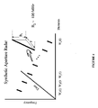
- FIG. 2 is a graphical representation of beam scan versus range for an antenna array operating at 10 Giga Hertz (GHz) for frequency shifts of 0 Hz, 200 Hz, and 400 Hz.
- GHz Giga Hertz
- FIG. 3 is a schematic diagram representation of an alternative embodiment of the present invention to provide more control over synthesis of transmitted signals.
- FIG. 4 is a graphical representation of an alternative embodiment of the present invention configured to achieve spotlight and strip map synthetic aperture radar simultaneously.
- FIG. 5 is a graphical representation of an alternative embodiment of the present invention configured to achieve synthetic aperture radar and ground moving target indication simultaneously.
- a generic range dependent beamformer includes a waveform generator 100 , a power divider network 110 , which is a conventional corporate feed network in the preferred embodiment, a transmitter/receiver module 120 , a waveform control subsystem 130 , and a radiating element array 140 .
- the waveform generator 100 synthesizes a signal to be transmitted. This signal is distributed to each of the first and second through the nth radiating/receiving elements 141 , 142 , 143 by means of a power divider network 110 .
- the signal output of each of the power divider network 110 outputs is input to a transmitter/receiver module 120 .
- the transmitter/receiver module 120 consists of a set of first and second through an nth modulator 151 , 152 , 153 followed by a first and a second through an nth radio frequency amplifier 161 , 162 , 163 and a first and second through an nth phase shifter 171 , 172 , 173 .
- the transmitter/receiver module 120 is controlled by a waveform control subsystem 130 , which sends a plurality of control signals for each of frequency 131 , 132 , 133 , amplitude 134 , 135 , 136 , and phase 137 , 138 , 139 .
- the outputs of the transmitter/receiver module 120 are provided to an antenna array 140 consisting of radiating/receiving elements 141 , 142 , 143 , which may, in turn, be subarrays of radiating/receiving elements.
- the actual number of transmitter/receiver module 120 signal outputs W 1 (t) . . . W N (t) 171 , 172 and 173 in the preferred embodiment depends upon the number of antenna elements 141 , 142 , and 143 . It follows that the number of modulators 151 , 152 and 153 , amplifiers 161 , 162 and 163 , and phase shifters 171 , 172 and 173 will be identical to the number of power divider 110 output branches.
- the waveform control subsystem 130 provides a plurality of frequency modulation control signals 131 , 132 , 133 , amplitude modulation control signals 134 , 135 , 136 and phase modulation control signals 137 , 138 , 139 to each respective frequency, amplitude and phase modulation section of the transmit/receive module 120 .
- the amplitude modulation control signal 134 , 135 , 136 permits power control as well as a mechanism to apply amplitude weighting for antenna sidelobe control.
- the phase modulation control signal 137 , 138 , 139 introduces a radiating/receive element-to-radiating/receive element phase shift for conventional or nominal beam steering, which is independent of the range-dependent beam steering afforded by the frequency modulation control signal 131 , 132 , 133 .
- the frequency modulation control signal provides a frequency shift which increases linearly across radiating/receive elements at any point in time.
- d is the spacing between any two adjacent elements 141 and 142 .
- the electrical path length becomes:
- the new terms due to frequency diversity are 2 ⁇ R 1 ⁇ f/c and ⁇ 2 ⁇ d sin ( ⁇ ) ⁇ f/c.
- the first term is range and frequency offset dependent, while the second term is dependent on the scan angle and frequency offset.
- the first new term shows that for a frequency diverse array in the present invention the apparent scan angle of the antenna now depends on range.
- FIG. 2 the effect of range-dependent beamforming for a frequency diverse array is depicted.
- Scan angle is plotted as a function of range for various frequency offsets at a nominal steering direction of 20 degrees. The most significant beam bending is achieved for larger frequency offsets.
- the frequency offset, ⁇ f must be less than the reciprocal of a receiver's coherent observation interval in order to make the individual waveforms inseparable.
- a plurality of waveform generators 101 , 102 through 103 output radio frequency signals which are provided to a transmit/receive module 125 .
- the outputs of the transmit/receive module 125 are provided to a like plurality of antenna radiating/receiving elements 141 , 142 through 143 .
- a waveform control subsystem 180 provides frequency modulation control signals 181 , 182 , 183 and phase modulation control signals 184 , 185 , 186 to the waveform generators 101 , 102 through 103 .
- the frequency and phase modulation control signals provide pulse-to-pulse and element-to-element frequency and phase diversity to the waveform generators as a function of time.
- the waveform control subsystem 180 also provides amplitude control signals 134 , 135 , 136 for power control and antenna weighting, and phase control signals 137 , 138 , 139 for nominal beam steering.
- the frequency modulation control signals 181 , 182 , 183 and the phase modulation control signals 184 , 185 , 186 permit the radiation of multiple signal modes at the same time.
- FIG. 4 a space-time illumination wherein the waveform generators 101 , 102 , 103 (see FIG. 3 ) output a plurality of linear frequency modulation signals to the transmit/receive module is depicted.
- a channel-to-channel frequency offset is also applied, as in the preferred embodiment.
- Different linear frequency modulation signals are applied to each antenna element 141 , 142 , 143 (see FIG. 3 ), to permit spotlight synthetic aperture radar and stripmap synthetic aperture radar modes at the same time.
- the described illumination permits a large aperture on transmit for high gain while enabling a plurality of spotlight synthetic aperture radars to operate simultaneously.
- the invention therefore defeats a fundamental limitation of conventional synthetic aperture radar, wherein a small aperture is required for long dwell and fine cross-range resolution.
- Synthetic aperture radar is an integration process which requires on the order of hundreds of megahertz of bandwidth to achieve sufficient range resolution for imaging.
- Ground moving target indication is a differencing process that requires only several megahertz of bandwidth for detection.
- the present invention permits modes to be constructed to support synthetic aperture radar and ground moving target indication at the same time by providing chirp diversity and phase modulation across the transmit/receive elements 141 , 142 through 143 , and processing all elements in combination and individually.
Landscapes
- Engineering & Computer Science (AREA)
- Remote Sensing (AREA)
- Radar, Positioning & Navigation (AREA)
- Physics & Mathematics (AREA)
- Electromagnetism (AREA)
- Computer Networks & Wireless Communication (AREA)
- General Physics & Mathematics (AREA)
- Variable-Direction Aerials And Aerial Arrays (AREA)
Abstract
Description
R 1 −R 2 =d sin (θ),
ψ=2πd/λ sin (θ)
An incremental phase shift ψ from element-to-element (linear phase progression across the aperture) will steer the antenna mainbeam to angle θ.
l 1 =R 1/λ1 =R 1 f 1 /c.
For
The electrical path length difference between
ψ=−2πd sin (θ) f 1 /c+2πR 1 Δf/−2πd sin (θ) Δf/c,
provided that Δf is negligible in computing the path length difference.
Claims (31)
Priority Applications (1)
| Application Number | Priority Date | Filing Date | Title |
|---|---|---|---|
| US11/312,805 US7319427B2 (en) | 2005-01-12 | 2005-12-20 | Frequency diverse array with independent modulation of frequency, amplitude, and phase |
Applications Claiming Priority (2)
| Application Number | Priority Date | Filing Date | Title |
|---|---|---|---|
| US64343105P | 2005-01-12 | 2005-01-12 | |
| US11/312,805 US7319427B2 (en) | 2005-01-12 | 2005-12-20 | Frequency diverse array with independent modulation of frequency, amplitude, and phase |
Related Child Applications (1)
| Application Number | Title | Priority Date | Filing Date |
|---|---|---|---|
| US11/974,942 Division US7511665B2 (en) | 2005-12-20 | 2007-10-16 | Method and apparatus for a frequency diverse array |
Publications (2)
| Publication Number | Publication Date |
|---|---|
| US20060152403A1 US20060152403A1 (en) | 2006-07-13 |
| US7319427B2 true US7319427B2 (en) | 2008-01-15 |
Family
ID=36652732
Family Applications (1)
| Application Number | Title | Priority Date | Filing Date |
|---|---|---|---|
| US11/312,805 Active 2026-07-26 US7319427B2 (en) | 2005-01-12 | 2005-12-20 | Frequency diverse array with independent modulation of frequency, amplitude, and phase |
Country Status (1)
| Country | Link |
|---|---|
| US (1) | US7319427B2 (en) |
Cited By (5)
| Publication number | Priority date | Publication date | Assignee | Title |
|---|---|---|---|---|
| US20160226142A1 (en) * | 2015-01-29 | 2016-08-04 | Robert Leroux | Phase control for antenna array |
| CN106656293A (en) * | 2016-12-21 | 2017-05-10 | 电子科技大学 | Physical layer security communication method based on frequency control array beamforming |
| CN108363058A (en) * | 2018-03-06 | 2018-08-03 | 电子科技大学 | Frequency controls the signal parameter design method of battle array imaging radar |
| US20180321369A1 (en) * | 2015-11-12 | 2018-11-08 | Israel Aerospace Industries Ltd. | Integrated electromagnetic seeker |
| US11218355B2 (en) * | 2017-07-10 | 2022-01-04 | Tm Ip Holdings, Llc | Multi-dimensional signal encoding |
Families Citing this family (34)
| Publication number | Priority date | Publication date | Assignee | Title |
|---|---|---|---|---|
| US7319427B2 (en) * | 2005-01-12 | 2008-01-15 | The United States Of America As Represented By The Secretary Of The Air Force | Frequency diverse array with independent modulation of frequency, amplitude, and phase |
| US8344933B1 (en) * | 2010-09-30 | 2013-01-01 | Rockwell Collins, Inc. | System and method for aircraft communications |
| US7511665B2 (en) * | 2005-12-20 | 2009-03-31 | The United States Of America As Represented By The Secretary Of The Air Force | Method and apparatus for a frequency diverse array |
| DE102006022814A1 (en) * | 2006-05-13 | 2007-11-15 | Deutsches Zentrum für Luft- und Raumfahrt e.V. | High-resolution Synthetic Aperture Side View Radar System using Digital Beamforming |
| US20090027265A1 (en) * | 2006-06-05 | 2009-01-29 | Oved Zucker | Frequency mode of locking phased arrays for synthesizing high order traveling interference patterns |
| US20090289833A1 (en) * | 2008-05-23 | 2009-11-26 | Johnson Paul A | Sparse array millimeter wave imaging system |
| US7973713B2 (en) * | 2008-10-15 | 2011-07-05 | Lockheed Martin Corporation | Element independent routerless beamforming |
| US8466829B1 (en) * | 2009-09-14 | 2013-06-18 | Lockheed Martin Corporation | Super-angular and range-resolution with phased array antenna and multifrequency dither |
| DE102013212079A1 (en) * | 2013-06-25 | 2015-01-08 | Robert Bosch Gmbh | Angle-resolving radar sensor |
| FR3008800B1 (en) * | 2013-07-19 | 2015-07-17 | Thales Sa | DEVICE FOR DETECTING ELECTROMAGNETIC SIGNALS |
| CN103592635B (en) * | 2013-11-11 | 2016-08-10 | 电子科技大学 | A Cognitive FDA Radar and Its Signal Emitting Method and Device |
| CN105044689A (en) * | 2015-04-14 | 2015-11-11 | 电子科技大学 | Frequency-controlled array-based RF stealth method and device |
| CN105116383B (en) * | 2015-07-15 | 2017-07-18 | 电子科技大学 | Produce method, device and the FDA radars of the launching beam of FDA radars |
| CN105137395B (en) * | 2015-07-29 | 2017-06-20 | 电子科技大学 | A kind of method and device of the difference on the frequency of setting FDA radars |
| CN105116385B (en) * | 2015-09-14 | 2017-06-20 | 电子科技大学 | A kind of method of generation FDA radar emission signals, device and FDA radars |
| US10320467B2 (en) * | 2015-09-29 | 2019-06-11 | The United States Of America, As Represented By The Secretary Of The Army | Frequency-based radio beamforming waveform transmission |
| US10079633B2 (en) | 2015-09-29 | 2018-09-18 | The United States Of America, As Represented By The Secretary Of The Army | Time-based and frequency-based radio beamforming waveform transmission |
| US10193612B2 (en) | 2015-09-29 | 2019-01-29 | The United States Of America, As Represented By The Secretary Of The Army | Time-based radio beamforming waveform transmission |
| CN105589070B (en) * | 2015-12-11 | 2017-12-05 | 桂林电子科技大学 | Radar target imaging method based on frequency diversity array |
| CN106788625B (en) * | 2016-12-21 | 2020-07-07 | 电子科技大学 | A frequency-controlled array secure communication method based on linear incremental frequency offset strategy |
| DE102017129933A1 (en) * | 2017-12-14 | 2019-06-19 | Conti Temic Microelectronic Gmbh | Method for acquiring environmental information by means of a radar system |
| GB201803239D0 (en) * | 2018-02-28 | 2018-04-11 | Secr Defence | A radio or sonic wave detector, transmitter, reciver and method thereof |
| CN108776337B (en) * | 2018-04-24 | 2021-11-05 | 桂林电子科技大学 | MIMO-FDA Ground Penetrating Radar Near Target 2D Imaging Method |
| CN108896983B (en) * | 2018-05-10 | 2022-09-20 | 电子科技大学 | Time-invariant space focusing beam forming method based on frequency control array |
| CN109375213B (en) * | 2018-08-08 | 2023-03-21 | 西安电子科技大学 | Frequency diversity array signal processing method based on subarray division |
| CN110109069B (en) * | 2019-05-14 | 2022-09-02 | 桂林电子科技大学 | Method for forming time-dependent-free frequency control array point-like interference wave beam |
| CN111123383B (en) * | 2019-12-25 | 2021-12-28 | 中国科学院上海微系统与信息技术研究所 | Sparse array signal processing method, device, circuit and imaging system |
| CN111273269B (en) * | 2020-02-18 | 2022-06-03 | 桂林电子科技大学 | A Radar Target Location Method Based on Frequency Diversity Array Based on IPSO-BP |
| CN111355517B (en) * | 2020-03-17 | 2021-04-06 | 电子科技大学 | A frequency-controlled array base station cooperative transmission method for high-speed mobile users |
| US11933876B2 (en) * | 2020-06-11 | 2024-03-19 | Qualcomm Incorporated | Combined frequency modulated continuous wave radar detection |
| CN112929306B (en) * | 2021-02-08 | 2022-11-11 | 西北工业大学 | A Multicast Frequency Controlled Array Method Based on Deep Learning Channel Estimation |
| CN113740808B (en) * | 2021-09-06 | 2024-07-05 | 阳光学院 | Cosine frequency offset frequency control array beam synthesis method |
| CN114285707B (en) * | 2021-12-23 | 2023-05-16 | 电子科技大学 | Frequency control array safety communication method based on chaos index modulation |
| US11506773B1 (en) * | 2022-05-23 | 2022-11-22 | Numerica Corporation | Compact, high-efficiency radar assembly |
Citations (14)
| Publication number | Priority date | Publication date | Assignee | Title |
|---|---|---|---|---|
| US2449553A (en) * | 1945-09-14 | 1948-09-21 | Paul G Hansel | Radio compass |
| US3042916A (en) * | 1957-01-10 | 1962-07-03 | Clarke Walter Wilson Hugh | Directional system for wave propagated signals |
| US4613974A (en) * | 1984-03-16 | 1986-09-23 | Vokac Peter R | Method and system for modulating a carrier signal |
| US5943363A (en) * | 1996-07-17 | 1999-08-24 | Stanford Telecommunications, Inc. | Digital spread spectrum GPS navigation receiver |
| US6040759A (en) * | 1998-02-17 | 2000-03-21 | Sanderson; Lelon Wayne | Communication system for providing broadband data services using a high-voltage cable of a power system |
| US6252693B1 (en) * | 1999-05-20 | 2001-06-26 | Ortel Corporation | Apparatus and method for reducing impairments from nonlinear fiber effects in 1550 nanometer external modulation links |
| US6594082B1 (en) * | 2000-06-05 | 2003-07-15 | Avanex Corporation | Optical wavelength router using reflective surfaces to direct output signals |
| US20040048574A1 (en) * | 2001-09-26 | 2004-03-11 | General Atomics | Method and apparatus for adapting multi-band ultra-wideband signaling to interference sources |
| US20050081636A1 (en) * | 2003-10-16 | 2005-04-21 | Barshinger James N. | Two dimensional phased arrays for volumetric ultrasonic inspection and methods of use |
| US20060063490A1 (en) * | 2003-03-12 | 2006-03-23 | Bader David M | System for simultaneously transmitting multiple RF signals using a composite waveform |
| US20060098761A1 (en) * | 2004-11-10 | 2006-05-11 | Motorola, Inc. | Multi-mode transmitter |
| US20060152403A1 (en) * | 2005-01-12 | 2006-07-13 | Wicks Michael C | Method and apparatus for a frequency diverse array |
| US20060273255A1 (en) * | 2001-11-26 | 2006-12-07 | Astrazeneca Ab | Method for forming the image in millimetre and sub-millimetre wave band (variants), system for forming the image in millimetre and sub-millimeter wave band (variants), diffuser light (variants) and transceiver (variants) |
| US20070092025A1 (en) * | 2005-10-21 | 2007-04-26 | Qi Bi | Method and apparatus for windowing orthogonal frequency division multiplexed signals |
-
2005
- 2005-12-20 US US11/312,805 patent/US7319427B2/en active Active
Patent Citations (14)
| Publication number | Priority date | Publication date | Assignee | Title |
|---|---|---|---|---|
| US2449553A (en) * | 1945-09-14 | 1948-09-21 | Paul G Hansel | Radio compass |
| US3042916A (en) * | 1957-01-10 | 1962-07-03 | Clarke Walter Wilson Hugh | Directional system for wave propagated signals |
| US4613974A (en) * | 1984-03-16 | 1986-09-23 | Vokac Peter R | Method and system for modulating a carrier signal |
| US5943363A (en) * | 1996-07-17 | 1999-08-24 | Stanford Telecommunications, Inc. | Digital spread spectrum GPS navigation receiver |
| US6040759A (en) * | 1998-02-17 | 2000-03-21 | Sanderson; Lelon Wayne | Communication system for providing broadband data services using a high-voltage cable of a power system |
| US6252693B1 (en) * | 1999-05-20 | 2001-06-26 | Ortel Corporation | Apparatus and method for reducing impairments from nonlinear fiber effects in 1550 nanometer external modulation links |
| US6594082B1 (en) * | 2000-06-05 | 2003-07-15 | Avanex Corporation | Optical wavelength router using reflective surfaces to direct output signals |
| US20040048574A1 (en) * | 2001-09-26 | 2004-03-11 | General Atomics | Method and apparatus for adapting multi-band ultra-wideband signaling to interference sources |
| US20060273255A1 (en) * | 2001-11-26 | 2006-12-07 | Astrazeneca Ab | Method for forming the image in millimetre and sub-millimetre wave band (variants), system for forming the image in millimetre and sub-millimeter wave band (variants), diffuser light (variants) and transceiver (variants) |
| US20060063490A1 (en) * | 2003-03-12 | 2006-03-23 | Bader David M | System for simultaneously transmitting multiple RF signals using a composite waveform |
| US20050081636A1 (en) * | 2003-10-16 | 2005-04-21 | Barshinger James N. | Two dimensional phased arrays for volumetric ultrasonic inspection and methods of use |
| US20060098761A1 (en) * | 2004-11-10 | 2006-05-11 | Motorola, Inc. | Multi-mode transmitter |
| US20060152403A1 (en) * | 2005-01-12 | 2006-07-13 | Wicks Michael C | Method and apparatus for a frequency diverse array |
| US20070092025A1 (en) * | 2005-10-21 | 2007-04-26 | Qi Bi | Method and apparatus for windowing orthogonal frequency division multiplexed signals |
Cited By (6)
| Publication number | Priority date | Publication date | Assignee | Title |
|---|---|---|---|---|
| US20160226142A1 (en) * | 2015-01-29 | 2016-08-04 | Robert Leroux | Phase control for antenna array |
| US20180321369A1 (en) * | 2015-11-12 | 2018-11-08 | Israel Aerospace Industries Ltd. | Integrated electromagnetic seeker |
| CN106656293A (en) * | 2016-12-21 | 2017-05-10 | 电子科技大学 | Physical layer security communication method based on frequency control array beamforming |
| CN106656293B (en) * | 2016-12-21 | 2020-07-28 | 电子科技大学 | Physical layer secure communication method based on frequency control array beam forming |
| US11218355B2 (en) * | 2017-07-10 | 2022-01-04 | Tm Ip Holdings, Llc | Multi-dimensional signal encoding |
| CN108363058A (en) * | 2018-03-06 | 2018-08-03 | 电子科技大学 | Frequency controls the signal parameter design method of battle array imaging radar |
Also Published As
| Publication number | Publication date |
|---|---|
| US20060152403A1 (en) | 2006-07-13 |
Similar Documents
| Publication | Publication Date | Title |
|---|---|---|
| US7319427B2 (en) | Frequency diverse array with independent modulation of frequency, amplitude, and phase | |
| US7511665B2 (en) | Method and apparatus for a frequency diverse array | |
| US5351053A (en) | Ultra wideband radar signal processor for electronically scanned arrays | |
| Antonik et al. | Multi-mission multi-mode waveform diversity | |
| Xu et al. | Range-angle-dependent beamforming of pulsed frequency diverse array | |
| Antonik et al. | Range-dependent beamforming using element level waveform diversity | |
| US9070972B2 (en) | Wideband beam forming device; wideband beam steering device and corresponding methods | |
| JP4835670B2 (en) | Antenna device | |
| US7646326B2 (en) | Method and apparatus for simultaneous synthetic aperture radar and moving target indication | |
| Younis et al. | On the pulse extension loss in digital beamforming SAR | |
| US3307188A (en) | Steerable antenna array and method of operating the same | |
| IL95815A (en) | Digital beamforming for multiple independent transmit beams. | |
| US20080122683A1 (en) | Monopulse antenna tracking and direction finding of multiple sources | |
| Pedross-Engel et al. | Enhanced resolution stripmap mode using dynamic metasurface antennas | |
| Brown | Active electronically scanned arrays: fundamentals and applications | |
| Yu et al. | A hybrid radar system with a phased transmitting array and a digital beamforming receiving array | |
| Babur et al. | Low-cost digital beamforming on receive in phased array radar | |
| US5706012A (en) | Radar system method using virtual interferometry | |
| US11509385B1 (en) | Angle diversity multiple input multiple output radar | |
| RU2516683C9 (en) | Active phased antenna array digital beamforming method when emitting and receiving chirp signal | |
| Eker | A conceptual evaluation of frequency diverse arrays and novel utilization of LFMCW | |
| JPH11183607A (en) | Synthetic aperture radar apparatus | |
| Mukherjee et al. | Compact MIMO Radar of Improved Angular Resolution Using Interleaved Array Geometry | |
| Frid et al. | Convex Optimization of Wideband Monopulse Arrays | |
| Ahmed et al. | Experimental study on multi-channel waveform agile beamforming and testbed calibration |
Legal Events
| Date | Code | Title | Description |
|---|---|---|---|
| AS | Assignment |
Owner name: UNITED STATES AIR FORCE, NEW YORK Free format text: ASSIGNMENT OF ASSIGNORS INTEREST;ASSIGNORS:WICKS, MICHAEL C.;ANTONIK, PAUL;REEL/FRAME:020076/0808 Effective date: 20051219 |
|
| STCF | Information on status: patent grant |
Free format text: PATENTED CASE |
|
| FPAY | Fee payment |
Year of fee payment: 4 |
|
| FPAY | Fee payment |
Year of fee payment: 8 |
|
| SULP | Surcharge for late payment |
Year of fee payment: 7 |
|
| MAFP | Maintenance fee payment |
Free format text: PAYMENT OF MAINTENANCE FEE, 12TH YEAR, LARGE ENTITY (ORIGINAL EVENT CODE: M1553); ENTITY STATUS OF PATENT OWNER: LARGE ENTITY Year of fee payment: 12 |
|
| AS | Assignment |
Owner name: GOVERNMENT OF THE UNITED STATES AS REPRESENTED BY THE SECRETARY OF THE AIR FORCE, NEW YORK Free format text: LICENSE;ASSIGNOR:RAIDER TECHNOLOGIES, LLC;REEL/FRAME:064589/0191 Effective date: 20230502 |