US731686A - Metal-working machine. - Google Patents
Metal-working machine. Download PDFInfo
- Publication number
- US731686A US731686A US8897302A US1902088973A US731686A US 731686 A US731686 A US 731686A US 8897302 A US8897302 A US 8897302A US 1902088973 A US1902088973 A US 1902088973A US 731686 A US731686 A US 731686A
- Authority
- US
- United States
- Prior art keywords
- swivel
- movement
- work
- screw
- working machine
- Prior art date
- Legal status (The legal status is an assumption and is not a legal conclusion. Google has not performed a legal analysis and makes no representation as to the accuracy of the status listed.)
- Expired - Lifetime
Links
Images

Classifications
-
- B—PERFORMING OPERATIONS; TRANSPORTING
- B23—MACHINE TOOLS; METAL-WORKING NOT OTHERWISE PROVIDED FOR
- B23Q—DETAILS, COMPONENTS, OR ACCESSORIES FOR MACHINE TOOLS, e.g. ARRANGEMENTS FOR COPYING OR CONTROLLING; MACHINE TOOLS IN GENERAL CHARACTERISED BY THE CONSTRUCTION OF PARTICULAR DETAILS OR COMPONENTS; COMBINATIONS OR ASSOCIATIONS OF METAL-WORKING MACHINES, NOT DIRECTED TO A PARTICULAR RESULT
- B23Q5/00—Driving or feeding mechanisms; Control arrangements therefor
- B23Q5/22—Feeding members carrying tools or work
- B23Q5/34—Feeding other members supporting tools or work, e.g. saddles, tool-slides, through mechanical transmission
- B23Q5/38—Feeding other members supporting tools or work, e.g. saddles, tool-slides, through mechanical transmission feeding continuously
- B23Q5/40—Feeding other members supporting tools or work, e.g. saddles, tool-slides, through mechanical transmission feeding continuously by feed shaft, e.g. lead screw
-
- B—PERFORMING OPERATIONS; TRANSPORTING
- B23—MACHINE TOOLS; METAL-WORKING NOT OTHERWISE PROVIDED FOR
- B23C—MILLING
- B23C1/00—Milling machines not designed for particular work or special operations
- B23C1/02—Milling machines not designed for particular work or special operations with one horizontal working-spindle
- B23C1/025—Milling machines not designed for particular work or special operations with one horizontal working-spindle with working-spindle movable in a fixed position
-
- Y—GENERAL TAGGING OF NEW TECHNOLOGICAL DEVELOPMENTS; GENERAL TAGGING OF CROSS-SECTIONAL TECHNOLOGIES SPANNING OVER SEVERAL SECTIONS OF THE IPC; TECHNICAL SUBJECTS COVERED BY FORMER USPC CROSS-REFERENCE ART COLLECTIONS [XRACs] AND DIGESTS
- Y10—TECHNICAL SUBJECTS COVERED BY FORMER USPC
- Y10T—TECHNICAL SUBJECTS COVERED BY FORMER US CLASSIFICATION
- Y10T409/00—Gear cutting, milling, or planing
- Y10T409/30—Milling
- Y10T409/304536—Milling including means to infeed work to cutter
- Y10T409/30532—Milling including means to infeed work to cutter with means to advance work or product
- Y10T409/305376—Vertically
-
- Y—GENERAL TAGGING OF NEW TECHNOLOGICAL DEVELOPMENTS; GENERAL TAGGING OF CROSS-SECTIONAL TECHNOLOGIES SPANNING OVER SEVERAL SECTIONS OF THE IPC; TECHNICAL SUBJECTS COVERED BY FORMER USPC CROSS-REFERENCE ART COLLECTIONS [XRACs] AND DIGESTS
- Y10—TECHNICAL SUBJECTS COVERED BY FORMER USPC
- Y10T—TECHNICAL SUBJECTS COVERED BY FORMER US CLASSIFICATION
- Y10T409/00—Gear cutting, milling, or planing
- Y10T409/30—Milling
- Y10T409/304536—Milling including means to infeed work to cutter
- Y10T409/305544—Milling including means to infeed work to cutter with work holder
- Y10T409/305656—Milling including means to infeed work to cutter with work holder including means to support work for rotation during operation
- Y10T409/305824—Milling including means to infeed work to cutter with work holder including means to support work for rotation during operation with angular movement of work
-
- Y—GENERAL TAGGING OF NEW TECHNOLOGICAL DEVELOPMENTS; GENERAL TAGGING OF CROSS-SECTIONAL TECHNOLOGIES SPANNING OVER SEVERAL SECTIONS OF THE IPC; TECHNICAL SUBJECTS COVERED BY FORMER USPC CROSS-REFERENCE ART COLLECTIONS [XRACs] AND DIGESTS
- Y10—TECHNICAL SUBJECTS COVERED BY FORMER USPC
- Y10T—TECHNICAL SUBJECTS COVERED BY FORMER US CLASSIFICATION
- Y10T409/00—Gear cutting, milling, or planing
- Y10T409/50—Planing
- Y10T409/504756—Planing with means to relatively infeed cutter and work
- Y10T409/506232—Reciprocating cutter infeed means
- Y10T409/506396—Reciprocating cutter horizontally
Definitions
- F EDERICK e. JOHNSON, OF HARTFORD, CONNECTICUT, AssICNoR TO THE F. o. JOI-I sON- COMPANY, OF. I-IARTFORD,-CONNECTICUT, A CORPORA- TIO OF CONNECTICUT.
- This invention relates to metal-working to machines, and more especially to that class thereof which are known in the art as planing or shaping machines; and it has for one of its objectsthe provision of a machine of this character which is simple in construction and yet is adapted to meet all the reject the provision in such a machine of a, work-table which may be adjusted vertically and laterally of'the machine andswhich may also be swung around a horizontal axis dis- 0 posed in alinement with the longitudinal center of the machine, while in addition thereto said table maybe swung around a horizontal axis disposed at right angles with said longitudinal center line.
- a ma- 5 chine constitutes a device the work-table of which may be adjusted or tilted into any de- 1 sired position and which may therefore be properly termed a universal shaping-machine.
- My invention has, furthermore, for its object the provision of means whereby the worktable may be fed relatively to and laterally of the cutter, irrespective of the particular inclination or position thereof.
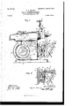
- the main driving shaft 11 having journaled therein the main driving shaft 11, which is provided at one end with a cone-pulley 12 and at its other end with a fly-wheel 13.
- a pinion 14 mounted on the shaft 11 is a pinion 14, in engagement with an intermediate 15, which may be journaled upon a stud 16 and meshing into a gear 17, mounted upon the shaft 18, also journaled in the base 10.
- the gear 17 carries a crank-pin 19, preferably disposed on said gear, so as to vary its throw to the required amount.
- This crankpin 19 projects into a slot 20 of an oscillatory lever 21, journaled at 22 on the base and having its upper end connected-ms, forinstance, by means of a link 23with a clampbolt 24, which is mounted for adjustment on the ram 25 and may be clamped in its adjusted position by a hand-nut 26.
- the contour of the slot 20 may be of any desired shape, I preferably form the same concentric with a center almost in alinement with that of the shaft 18 when the lever is in its forward position, so that therefore the crank-pin or actuator 19 may have a comparatively great angular movement and yet produce onlya very small advancing movement of the lever "21, and consequently of the ram or tool-carrier 25.
- the ram 25 is shown provided at its forward end with the head 27, carrying a slide 28, which may be adjusted vertically, as, for instance, by a screw 29 in the ordinary man ner.
- Attached to the slide 28 is a swivel 30, on which the clapper 31 may be pivotally supported, as at 32.
- the clapper 31 has in this instance a tool-post 33, provided with a clam ping-screw 34 for securing a cutting-tool O in place thereon.
- the front end of the base is provided with ways 35, adapted to receive a cross-bar 36,
- cross-bar 36 which is movable vertically on said ways and may be held in its position by gib-screws, while the cross-bar 36 is provided with ways 37 to receive a cross-slide 38, which is shown I 41, serving as a pivot for a table support or swivel 42, which is thus mounted for rotation on said slide and may be held in place thereon by a washer 43 and a nut 44, which in the present instance is in screw-threaded engagement with a bolt 39, forming a part of or secured to the nut 39, above mentioned.
- a cross-slide 38 which is shown I 41, serving as a pivot for a table support or swivel 42, which is thus mounted for rotation on said slide and may be held in place thereon by a washer 43 and a nut 44, which in the present instance is in screw-threaded engagement with a bolt 39, forming a part of or secured to the nut 39, above mentioned.
- the projection 41 serves as a trunnion for the swivel 42, which may be swung around the axis of said trunnion, so as to tilt the same laterally of the machine, said swivel 42 being provided with slots 42, (see Fig. 2,) through which bolts 43 may pass and enter one of a series of concentrically disposed screwthreaded apertures 44 in the cross-slide 38, in this manner providing for a greater range of tilting movement of the swivel 42 than the length of the slot 42 would naturally permit.
- a table 45 Pivoted for vertical movement on the swivel 42 is a table 45, having a plurality of ears 46 alternating with projections 47, formed on the swivel 42, while a rod 48 may pass through all the ears 46 and projections 47, and thus serve substantially as a hingerod for the table 45 on the swivel 42. It will therefore be seen that the table 45 may be swung upward or downward from its horizontal position, (shown in Fig. 1,) so that the work may be presented to the cutting-tool at any desired angle.
- the work which is herein denoted by NV, may be caused to rest at one side against a stop or jaw 49, having a lip 49', adapted to enter a groove 50 in the table, while at its front end the table may carry a clampingblock 51, provided with a lip 52, also adapted to enter a groove 50, and provided with setscrews 53 for forcing the work vW against the bar above referred to.
- Means are provided for securing the table 45 in its vertically-adjusted position, the table having at its under side ears 54, to which links 55 are pivoted.
- the links 55 are slotted, as shown at 56, to straddle clamping-bolts 57, which may be in screw-threaded engagement with ears 58, provided on the swivel 42.
- the lateral feed or traverse movement of the table, or more particularly of the crossslide 38 on the bar 36 may be accomplished in any desired manner, the mechanism shown in the drawings comprising as a prime mover a crank-pin 60, secured to the outer end of the shaft 18 and connected by a link 61 with a vertically-disposed arm 62, secured upon a rod or shaft 63, which is journaled in a bearing 64 on the bar 36.
- the arm 62 may be slotted to vary the angular movement of said arm, and consequently that of the shaft 63.
- an arm 65 secured upon the rock-shaft 63 is an arm 65, the free end of which may be connected by a link 66 with an arm 67, journaled upon the feed-screw 40, above mentioned, and having a click 68, adapted for engagement with a ratchet-wheel 69, secu'red upon said screw 40, so that said screw may be rotated in either direction and the cross-slide 38 moved laterally on the table in conformity with the movement of the screw 40, the latter having also a crank 70, whereby said screw may be operated by hand when the click 68 is disengaged from the ratchet 69, as shown in Fig. 1.
- a machine of the type set forth the combination with a base, a cross-bar mounted for vertical movement thereon, a slide transversely movable on said bar, a swivel carried by said slide, and a table pivoted to said swivel, said table carrying Work-securing means, the axis of said pivot lying at right angles to'the axis of the swivel, and means for securing said table to said swivel in an adjusted position, substantially as described.
Landscapes
- Engineering & Computer Science (AREA)
- Mechanical Engineering (AREA)
- Sawing (AREA)
Description
No. 731,6216. PATENTED JUNE 23, 1903..
F. G. JOHNSON. METAL WORKING MACHINE.
' APPLICATION FILED JAN. 9, 1902.
to MODEL. 2 snnms-snnm 1.
PATENTED JUNE 23. 1903.
P. G. JOHNSON. METAL WORKING MACHINE.
APPLICATION rum) JAN. 9. 1902.
2 SHEETS-SHEET ,2.
7N0 MODEL.
KN WW 1 @KN "ms uonms wnzns co. PHOID-LITHO. WA$H1NGTON, u. r.
UNITED STATES Patented June 23, 1903.
PATENT OFFICE.
F EDERICK e. JOHNSON, OF HARTFORD, CONNECTICUT, AssICNoR TO THE F. o. JOI-I sON- COMPANY, OF. I-IARTFORD,-CONNECTICUT, A CORPORA- TIO OF CONNECTICUT.
M ETAL-WORKING MACHINE.
SPECIFICATION formingpart of Letters Patent N 0. 731,686, dated June 23, 1903. Application filed January 9, 1902. Serial No; 88,973. (No model.)
To all whom it may concern.-
Be it known that I, FREDERICK G. J OHN- SON, a citizen of the United States, and a resi dent of Hartford, in the county of Hartford and State of Connecticut, have invented certain new and useful Improvements in Metalt 1Working Machines, of which the followingis a full, clear, and exact specification.
This invention relates to metal-working to machines, and more especially to that class thereof which are known in the art as planing or shaping machines; and it has for one of its objectsthe provision of a machine of this character which is simple in construction and yet is adapted to meet all the reject the provision in such a machine of a, work-table which may be adjusted vertically and laterally of'the machine andswhich may also be swung around a horizontal axis dis- 0 posed in alinement with the longitudinal center of the machine, while in addition thereto said table maybe swung around a horizontal axis disposed at right angles with said longitudinal center line. In this manner a ma- 5 chine constitutes a device the work-table of which may be adjusted or tilted into any de- 1 sired position and which may therefore be properly termed a universal shaping-machine.
My invention has, furthermore, for its object the provision of means whereby the worktable may be fed relatively to and laterally of the cutter, irrespective of the particular inclination or position thereof.
Further objects of my invention may be found in the particular construction and organization of some of the elements, as will be hereinafter described, and particularly pointed out in the claim.
having journaled therein the main driving shaft 11, which is provided at one end with a cone-pulley 12 and at its other end with a fly-wheel 13. Mounted on the shaft 11 is a pinion 14, in engagement with an intermediate 15, which may be journaled upon a stud 16 and meshing into a gear 17, mounted upon the shaft 18, also journaled in the base 10. The gear 17 carries a crank-pin 19, preferably disposed on said gear, so as to vary its throw to the required amount. This crankpin 19 projects into a slot 20 of an oscillatory lever 21, journaled at 22 on the base and having its upper end connected-ms, forinstance, by means of a link 23with a clampbolt 24, Which is mounted for adjustment on the ram 25 and may be clamped in its adjusted position by a hand-nut 26.
By referring to Fig. 1 it will be seen that the slot 20is curved, so that as the crank-pin l9 revolves the movement of the lever 21 will be comparatively rapid when causing the rearward movement of the ram 25, While, on
I the other hand, the forward movement of the latter during its working stroke will bematerially retarded, so that all liability of the cutting-tool breaking out the work will be obviated.
While primarily the contour of the slot 20 may be of any desired shape, I preferably form the same concentric with a center almost in alinement with that of the shaft 18 when the lever is in its forward position, so that therefore the crank-pin or actuator 19 may have a comparatively great angular movement and yet produce onlya very small advancing movement of the lever "21, and consequently of the ram or tool-carrier 25.
From the organization of the mechanism herein shown it will be understood that when the crank-pin 19 is traveling through its arc of movement at the left of the shaft 18 the movement of the lever 21 will naturally be more rapid than when traveling in the are at the right of said shaft and that therefore they movement of the ram during its working stroke will be slower than that during its return stroke.
The ram 25 is shown provided at its forward end with the head 27, carrying a slide 28, which may be adjusted vertically, as, for instance, by a screw 29 in the ordinary man ner. Attached to the slide 28 is a swivel 30, on which the clapper 31 may be pivotally supported, as at 32. The clapper 31 has in this instance a tool-post 33, provided with a clam ping-screw 34 for securing a cutting-tool O in place thereon.
The front end of the base is provided with ways 35, adapted to receive a cross-bar 36,
which is movable vertically on said ways and may be held in its position by gib-screws, while the cross-bar 36 is provided with ways 37 to receive a cross-slide 38, which is shown I 41, serving as a pivot for a table support or swivel 42, which is thus mounted for rotation on said slide and may be held in place thereon by a washer 43 and a nut 44, which in the present instance is in screw-threaded engagement with a bolt 39, forming a part of or secured to the nut 39, above mentioned. The projection 41 serves as a trunnion for the swivel 42, which may be swung around the axis of said trunnion, so as to tilt the same laterally of the machine, said swivel 42 being provided with slots 42, (see Fig. 2,) through which bolts 43 may pass and enter one of a series of concentrically disposed screwthreaded apertures 44 in the cross-slide 38, in this manner providing for a greater range of tilting movement of the swivel 42 than the length of the slot 42 would naturally permit.
Pivoted for vertical movement on the swivel 42 is a table 45, having a plurality of ears 46 alternating with projections 47, formed on the swivel 42, while a rod 48 may pass through all the ears 46 and projections 47, and thus serve substantially as a hingerod for the table 45 on the swivel 42. It will therefore be seen that the table 45 may be swung upward or downward from its horizontal position, (shown in Fig. 1,) so that the work may be presented to the cutting-tool at any desired angle.
The work, which is herein denoted by NV, may be caused to rest at one side against a stop or jaw 49, having a lip 49', adapted to enter a groove 50 in the table, while at its front end the table may carry a clampingblock 51, provided with a lip 52, also adapted to enter a groove 50, and provided with setscrews 53 for forcing the work vW against the bar above referred to.
Means are provided for securing the table 45 in its vertically-adjusted position, the table having at its under side ears 54, to which links 55 are pivoted. The links 55 are slotted, as shown at 56, to straddle clamping-bolts 57, which may be in screw-threaded engagement with ears 58, provided on the swivel 42.
By the organization of the elements described I am enabled, first, to firmly secure the work upon the table; secondly, to tilt the work upwardly or downwardly, as the case may be; thirdly, to tilt 'the work laterally in either direction; fourthly, to move the table bodily up or down and without in any way altering its other position, and, fifthly, to feed the work laterally of the cuttingtool, which of course will produce a chip laterally of the work, while, on the other hand, the depth of the cut may be regulated by the adjustment of the cutting-tool in a vertical direction either in the tool-post or by rotating the screw 29.
The lateral feed or traverse movement of the table, or more particularly of the crossslide 38 on the bar 36, may be accomplished in any desired manner, the mechanism shown in the drawings comprising as a prime mover a crank-pin 60, secured to the outer end of the shaft 18 and connected by a link 61 with a vertically-disposed arm 62, secured upon a rod or shaft 63, which is journaled in a bearing 64 on the bar 36. The arm 62 may be slotted to vary the angular movement of said arm, and consequently that of the shaft 63. Also secured upon the rock-shaft 63 is an arm 65, the free end of which may be connected by a link 66 with an arm 67, journaled upon the feed-screw 40, above mentioned, and having a click 68, adapted for engagement with a ratchet-wheel 69, secu'red upon said screw 40, so that said screw may be rotated in either direction and the cross-slide 38 moved laterally on the table in conformity with the movement of the screw 40, the latter having also a crank 70, whereby said screw may be operated by hand when the click 68 is disengaged from the ratchet 69, as shown in Fig. 1.
Having described my invention, what I claim as new, and desire to secure by Letters Patent, is
In a machine of the type set forth the combination with a base, a cross-bar mounted for vertical movement thereon, a slide transversely movable on said bar, a swivel carried by said slide, and a table pivoted to said swivel, said table carrying Work-securing means, the axis of said pivot lying at right angles to'the axis of the swivel, and means for securing said table to said swivel in an adjusted position, substantially as described.
FREDERICK G. JOHNSON.
Witnesses:
JOHN R. ALOOTT, CHAS. F. SCHMELZ.
Priority Applications (1)
| Application Number | Priority Date | Filing Date | Title |
|---|---|---|---|
| US8897302A US731686A (en) | 1902-01-09 | 1902-01-09 | Metal-working machine. |
Applications Claiming Priority (1)
| Application Number | Priority Date | Filing Date | Title |
|---|---|---|---|
| US8897302A US731686A (en) | 1902-01-09 | 1902-01-09 | Metal-working machine. |
Publications (1)
| Publication Number | Publication Date |
|---|---|
| US731686A true US731686A (en) | 1903-06-23 |
Family
ID=2800193
Family Applications (1)
| Application Number | Title | Priority Date | Filing Date |
|---|---|---|---|
| US8897302A Expired - Lifetime US731686A (en) | 1902-01-09 | 1902-01-09 | Metal-working machine. |
Country Status (1)
| Country | Link |
|---|---|
| US (1) | US731686A (en) |
Cited By (2)
| Publication number | Priority date | Publication date | Assignee | Title |
|---|---|---|---|---|
| US3051060A (en) * | 1959-11-25 | 1962-08-28 | Western Electric Co | Device for supporting and moving an article in a machine |
| US4924843A (en) * | 1988-11-28 | 1990-05-15 | Waren Jerry B | Masonry saw jig |
-
1902
- 1902-01-09 US US8897302A patent/US731686A/en not_active Expired - Lifetime
Cited By (2)
| Publication number | Priority date | Publication date | Assignee | Title |
|---|---|---|---|---|
| US3051060A (en) * | 1959-11-25 | 1962-08-28 | Western Electric Co | Device for supporting and moving an article in a machine |
| US4924843A (en) * | 1988-11-28 | 1990-05-15 | Waren Jerry B | Masonry saw jig |
Similar Documents
| Publication | Publication Date | Title |
|---|---|---|
| US731686A (en) | Metal-working machine. | |
| US478544A (en) | And edward cheshire | |
| US1366005A (en) | Cutting-tool | |
| US1084544A (en) | Shaper. | |
| US1322352A (en) | Automatic lathe | |
| US479606A (en) | Half to james w | |
| US258120A (en) | Metal-planing machine | |
| US683955A (en) | Metal shaping or cutting machine. | |
| US293892A (en) | William o | |
| US437414A (en) | Tenoning-machine | |
| US776501A (en) | Slotting-machine. | |
| US557594A (en) | Andrew b | |
| US879531A (en) | Gear-generating machine. | |
| US724676A (en) | Lathe for turning irregular forms. | |
| US542461A (en) | Wiilling-machine | |
| US2441915A (en) | Grooving machine | |
| US409451A (en) | James c | |
| US183298A (en) | Improvement in gear-planers | |
| US560574A (en) | delin | |
| US846728A (en) | Shaping-machine. | |
| US558005A (en) | Wood-molding machine | |
| US872728A (en) | Machine for cutting screw-threads. | |
| US1100990A (en) | Metal-shaping machine. | |
| US659461A (en) | Engraving and die-sinking machine. | |
| US509467A (en) | Tool-controlling mechanism for gear-planers |