US7265649B1 - Flexible inductive resistivity device - Google Patents
Flexible inductive resistivity device Download PDFInfo
- Publication number
- US7265649B1 US7265649B1 US11/676,494 US67649407A US7265649B1 US 7265649 B1 US7265649 B1 US 7265649B1 US 67649407 A US67649407 A US 67649407A US 7265649 B1 US7265649 B1 US 7265649B1
- Authority
- US
- United States
- Prior art keywords
- resistivity tool
- tool
- induction
- induction resistivity
- coil
- Prior art date
- Legal status (The legal status is an assumption and is not a legal conclusion. Google has not performed a legal analysis and makes no representation as to the accuracy of the status listed.)
- Expired - Fee Related
Links
Images


Classifications
-
- H—ELECTRICITY
- H01—ELECTRIC ELEMENTS
- H01Q—ANTENNAS, i.e. RADIO AERIALS
- H01Q1/00—Details of, or arrangements associated with, antennas
- H01Q1/04—Adaptation for subterranean or subaqueous use
-
- H—ELECTRICITY
- H01—ELECTRIC ELEMENTS
- H01F—MAGNETS; INDUCTANCES; TRANSFORMERS; SELECTION OF MATERIALS FOR THEIR MAGNETIC PROPERTIES
- H01F27/00—Details of transformers or inductances, in general
- H01F27/34—Special means for preventing or reducing unwanted electric or magnetic effects, e.g. no-load losses, reactive currents, harmonics, oscillations, leakage fields
- H01F27/36—Electric or magnetic shields or screens
- H01F27/366—Electric or magnetic shields or screens made of ferromagnetic material
-
- H—ELECTRICITY
- H04—ELECTRIC COMMUNICATION TECHNIQUE
- H04B—TRANSMISSION
- H04B5/00—Near-field transmission systems, e.g. inductive or capacitive transmission systems
- H04B5/70—Near-field transmission systems, e.g. inductive or capacitive transmission systems specially adapted for specific purposes
- H04B5/73—Near-field transmission systems, e.g. inductive or capacitive transmission systems specially adapted for specific purposes for taking measurements, e.g. using sensing coils
-
- E—FIXED CONSTRUCTIONS
- E21—EARTH OR ROCK DRILLING; MINING
- E21B—EARTH OR ROCK DRILLING; OBTAINING OIL, GAS, WATER, SOLUBLE OR MELTABLE MATERIALS OR A SLURRY OF MINERALS FROM WELLS
- E21B47/00—Survey of boreholes or wells
- E21B47/01—Devices for supporting measuring instruments on drill bits, pipes, rods or wirelines; Protecting measuring instruments in boreholes against heat, shock, pressure or the like
-
- H—ELECTRICITY
- H01—ELECTRIC ELEMENTS
- H01F—MAGNETS; INDUCTANCES; TRANSFORMERS; SELECTION OF MATERIALS FOR THEIR MAGNETIC PROPERTIES
- H01F27/00—Details of transformers or inductances, in general
- H01F27/34—Special means for preventing or reducing unwanted electric or magnetic effects, e.g. no-load losses, reactive currents, harmonics, oscillations, leakage fields
- H01F27/36—Electric or magnetic shields or screens
-
- H—ELECTRICITY
- H01—ELECTRIC ELEMENTS
- H01F—MAGNETS; INDUCTANCES; TRANSFORMERS; SELECTION OF MATERIALS FOR THEIR MAGNETIC PROPERTIES
- H01F38/00—Adaptations of transformers or inductances for specific applications or functions
- H01F38/14—Inductive couplings
Definitions
- the present invention relates to the field of downhole oil, gas, horizontal, and/or geothermal exploration and more particularly to the field of resistivity tools for tool strings employed in such exploration.
- Logging-while-drilling refers to a set of processes commonly used by the industry to obtain information about a formation during the drilling process in order to transmit the information from components located downhole on oil and gas drilling strings to the ground's surface.
- Various sensors and methods have been developed to obtain and transfer formation information to the surface. Due to the extreme conditions present in downhole environments, sensors must be used that can withstand great stresses.
- Part of the difficulty comes from the fact that the operating environment can be extremely harsh, including temperatures as high as 200° C., pressures as high as 25,000 psi, and extremely abrasive and chemically corrosive conditions.
- Another source of difficulty comes from the fact that a drill string is made up of hundreds of components, such as sections of drill pipe and various downhole tools. Since these components are connected serially to create a drill string that may stretch for thousands of feet below the earth's surface, reliability is imperative. A failure in any essential downhole component can bring the whole system down and require an expensive “roundtrip” of the drill string to replace the defective component.
- the prior art contains references to drill bits with sensors or other apparatus for data retrieval.
- U.S. Pat. No. 6,814,162 to Moran, et al. which is incorporated by reference for all that it contains, discloses a drill bit, comprising a bit body, a sensor disposed in the bit body, a single journal removably mounted to the bit body, and a roller cone rotatably mounted to the single journal.
- the drill bit may also comprise a short-hop telemetry transmission device adapted to transmit data from the sensor to a measurement-while-drilling device located above the drill bit on the drill string.
- U.S. Pat. No. 6,913,095 to Krueger which is incorporated by reference for all that it contains, discloses a closed-loop drilling system that utilizes a bottom hole assembly (“BHA”) having a steering assembly having a rotating member and a non rotating sleeve disposed thereon.
- the sleeve has a plurality of expandable force application members that engage a borehole wall.
- a power source and associated electronics for energizing the force application members are located outside of the non rotating sleeve.
- U.S. Pat. No. 6,538,447 to Bittar which is incorporated by reference for all that it contains, discloses a multi-mode resistivity tool for use in a logging-while-drilling system that includes an asymmetric transmitter design with multiple transmitters capable of generating electromagnetic signals at multiple depths of investigation.
- U.S. Pat. No. 6,359,438 to Bittar which is incorporated by reference for all that it contains, discloses a resistivity tool for use in an LWD system that includes a transmitter array with multiple transmitters positioned above a pair of receivers. The transmitters are selectively energized, causing current to be induced in the collar of the tool.
- U.S. Pat. No. 7,116,199 to Hall, et al which is incorporated by reference for all that it contains, discloses an inductive coupler for downhole components.
- the inductive coupler includes an annular housing having a recess defined by a bottom portion and two opposing side wall portions.
- a plurality of generally U-shaped magnetically conductive electrically insulating segments, preferably comprised of ferrite, are disposed in the recess and aligned so as to form a circular trough.
- an induction resistivity tool incorporated into a downhole tool string comprises a downhole tool string component comprising a mid-body disposed intermediate first and second tool joints adapted for connection to adjacent tool string components.
- the mid-body comprises a central bore formed within a tubular wall of the component, the tubular wall comprising an inner and outer diameter.
- At least one annular radial recess is formed in the outer diameter of the mid-body and comprises a coil adapted to transceive induction signals outwardly from the mid-body, and at least one flexible ring of magnetically conducting material is disposed intermediate the coil and a surface of the recess and arranged within the annular radial recess such that it filters a range of frequencies of the induction signals.
- the resistivity tool may comprise a sleeve adapted to protect the coil, groove, or flexible ring from mud and/or debris.
- the resistivity tool may be incorporated into a bottom hole assembly, and may be in communication with a downhole network.
- the coil may comprise between 1 and 15 turns of coil. The coil may be separated from the outer diameter by insulating material.
- the flexible ring of magnetically conducting material may comprise segments of ferrite joined flexibly together with a flexible backing. Adjacent segments of ferrite may be connected by the use of an adhesive, frame, brace, hinge, tie, string, tape, or combinations thereof.
- the flexible ring may comprise a flexible matrix filled with a magnetically conductive material
- the flexible ring may comprise a generally circular trough geometry, a generally cylindrical geometry, a dual trough geometry, or combinations thereof.
- a segment of the circular trough may comprise a bottom end, two sides and an open end defined by a plane comprising a distal end of each of the sides.
- the plane of the open end may be generally parallel to a longitudinal surface of the inner diameter of the tubular wall.
- the plane of the open end may form an angle of between 1 and 89 degrees with a longitudinal surface of the inner diameter of the tubular wall.
- the radial recess may comprise at least two flexible rings tilted at different angles.
- the flexible ring may comprise a material selected from the group consisting of soft iron, ferrite, a nickel alloy, a silicon iron alloy, a cobalt iron alloy, a mu-metal, a laminated mu-metal, barium, strontium, carbonate, samarium, cobalt, neodymium, boron, a metal oxide, ceramics, cermets, ceramic composites, rare earth metals, an aerogel composite, polymers, organic materials, thermoset polymers, vinyl, a synthetic binder, thermoplastic polymers, an epoxy, natural rubber, fiberglass, carbon fiber composite, polyurethane, silicon, a fluorinated polymer, grease, polytetrafluoroethylene, a perfluororoalkoxy compound, resin, potting material, and combinations thereof.
- the flexible ring may comprise at least two flexibly attached segments that are adapted to allow the flexible ring to open and close. In some embodiments the flexible ring may comprise one continuous piece.
- the magnetically conductive material may comprise a relative magnetic permeability range of between 100 and 20000.
- the magnetically conductive material may comprise ferrite in the form of fibers, strips, shavings, powder, crystals, formed pieces or combinations thereof.
- the induction resistivity tool may comprise a plurality of coils in the same radial recess or in a plurality of radial recesses. Each coil may be selectively energized.
- FIG. 1 is a cross-sectional diagram of an embodiment of a downhole tool string.
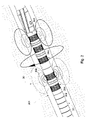
- FIG. 2 is a perspective diagram of an embodiment of an inductive resistivity tool.
- FIG. 3 is a cross-sectional diagram of an embodiment of a transceiver in an inductive resistivity tool.
- FIG. 4 is a perspective diagram of an embodiment of a coil disposed in an embodiment of a flexible ring.
- FIG. 5 is a diagram of power verses frequency in a bare wire and in a ferrite shielded wire.
- FIG. 6 is a perspective diagram of another embodiment of a coil disposed in another embodiment of a flexible ring.
- FIG. 7 is a cross-sectional diagram an embodiment of a coil disposed in an embodiment of an annular recess.
- FIG. 8 is a cross-sectional diagram another embodiment of a coil disposed in an embodiment of an annular recess.
- FIG. 9 is a cross-sectional diagram another embodiment of a coil disposed in an embodiment of an annular recess.
- FIG. 10 is a cross-sectional diagram another embodiment of a coil disposed in an embodiment of an annular recess.
- FIG. 11 is a cross-sectional diagram another embodiment of a coil disposed in an embodiment of an annular recess.
- FIG. 12 is a cross-sectional diagram another embodiment of a coil disposed in an embodiment of an annular recess.
- FIG. 13 is a perspective diagram of an embodiment of a flexible ring.
- FIG. 14 is a perspective diagram of another embodiment of a flexible ring.
- FIG. 15 is a perspective diagram of another embodiment of a flexible ring.
- FIG. 16 is a perspective diagram of another embodiment of a flexible ring.
- a downhole tool string 31 may be suspended by a derrick 32 .
- the tool string may comprise one or more downhole components 36 , linked together in a tool string 31 and in communication with surface equipment 33 through a downhole network. Having a network in the tool string 31 may enable high-speed communication between each device connected to it and facilitate the transmission and receipt of data between sensors, energy sources, and energy receivers.
- the tool string 31 or surface equipment 33 may comprise an energy source or multiple energy sources.
- the energy source may transmit electrical current to one or more downhole components 36 on the bottom hole assembly 37 or along the tool string 31 .
- one or more downhole component 36 may comprise sensors. These sensors may sense gamma rays, radioactive energy, resistivity, torque, pressure, or other drilling dynamics measurements or combinations thereof from the formation being drilled. Any combination of downhole components 36 in a tool string 31 may be compatible with the present invention.
- the drill string 31 may comprise an energy source that is radioactive or emits subatomic particles, such as gamma ray or neutron sources.
- the neutron source may comprise an Americium Beryllium source or it may comprise a pulsed neutron generator which uses deuterium and/or tritium ions. Data may be transmitted up and down the tool string 31 and between different tool components 36 .
- Data may be transmitted along the tool string 31 through techniques known in the art.
- a preferred method of downhole data transmission using inductive couplers disposed in tool joints is disclosed in the U.S. Pat. No. 6,670,880 to Hall, et al, which is herein incorporated by reference for all it discloses.
- An alternate data transmission path may comprise direct electrical contacts in tool joints such as in the system disclosed in U.S. Pat. No. 6,688,396 to Floerke, et al., which is herein incorporated by reference for all that it discloses.
- Another data transmission system that may also be adapted for use with the present invention is disclosed in U.S. Pat. No.
- alternative forms of telemetry may be used to communicate with the downhole components 36 , such as telemetry systems that communicate through the drilling mud or through the earth. Such telemetry systems may use electromagnetic or acoustic waves.
- the alternative forms of telemetry may be the primary telemetry system for communication with the tool string 31 or they may be back-up systems designed to maintain some communication if the primary telemetry system fails.
- a data swivel 34 or a wireless top-hole data connection may facilitate the transfer of data between components 36 of the rotatable tool string 31 and the stationary surface equipment 33 .
- Downhole tool string components 36 may comprise drill pipes, jars, shock absorbers, mud hammers, air hammers, mud motors, turbines, reamers, under-reamers, fishing tools, steering elements, MWD tools, LWD tools, seismic sources, seismic receivers, pumps, perforators, packers, other tools with an explosive charge, mud-pulse sirens.
- Downhole LWD Tools may be located in the bottom hole assembly 37 or along the length of the downhole tool string 31 .
- the tools may be inductive resistivity tools 35 , sensors, drill bits, motors, hammers, steering elements, links, jars, seismic sources, seismic receivers, sensors, and other tools that aid in the operations of the downhole tool string 31 .
- sensors are useful downhole such as pressure sensors, temperature sensors, inclinometers, thermocouplers, accelerometers, and imaging devices.
- the downhole tool string 31 is a drill string. In other embodiments the downhole tool string 31 is part of a production well. In the present embodiment, an embodiment of a resistivity tool 35 in accordance with the present invention is shown producing a magnetic field 30 and projecting the magnetic field 30 through the formation 40 .
- the tool string 31 may comprise an acoustic sensor system, hydrophone system, an annular pressure sensor system, formation pressure sensor system, a gamma ray sensor system, density neutron sensor system, a geophone array system, or an accelerometer system, directional drilling system, an inclination sensor system that may include a gyroscopic device, a drilling dynamics system, another system that may be used to evaluate formation properties, an active sensor, a passive sensor, or combinations thereof.
- Control equipment may be in communication with the downhole tool string components 36 through an electrically conductive medium.
- a coaxial cable, wire, twisted pair of wires or combinations thereof may travel from the surface to at least one downhole tool string component.
- the medium may be in inductive or electrical communication with each other through couplers positioned so as to allow signal transmission across the connection of the downhole component and the tool string.
- the couplers may be disposed within recesses in either a primary or secondary shoulder of the connection or they may be disposed within inserts positioned within the bores of the drill bit assembly and the downhole tool string component.
- the control equipment may then change drilling parameters according to the data received to optimize drilling efficiency. Operation of the drill string 31 may include the ability to steer the direction of drilling based on the data.
- an embodiment of an inductive resistivity tool 201 is shown as part of a downhole drill string 31 .
- the resistivity tool 201 is shown intermediate first and second tool joints 202 , 203 .
- a magnetic field 30 is shown being produced by two transmitting transceivers 204 , and being received by three receiving transceivers 205 .
- the magnetic field 30 is induced into the formation, which then in turn induces the receivers 205 .
- the resistivity of the formation may be determined.
- resistivity measurements may be used to determine the petroleum potential of a formation during the drilling process.
- a sleeve 206 may be disposed around the components of the resistivity tool 201 to protect them from mud and/or debris.
- FIG. 3 a cross sectional view of an embodiment of a portion of a resistivity tool 201 is shown without a sleeve 206 .
- a central bore 301 is disclosed through which drilling mud may be transferred.
- the central bore 301 is formed within a tubular wall comprising an inner diameter 302 and an outer diameter 303 .
- An annular radial recess 304 is shown formed in the outer diameter 303 .
- a coil 305 is placed within the radial recess 304 and may act as a transceiver to project induction signals outward from the resistivity tool 201 .
- FIG. 4 an enlarged embodiment of a coil 305 is shown disposed in a radial recess 304 . Although in the present embodiment of the invention five turns of coil 305 are shown, any number of turns of coil 305 may be compatible with the invention.
- An embodiment of a flexible ring of magnetically conducting material 401 is shown disposed intermediate the coil 305 and a surface 408 of the radial recess 304 . As electrical current is passed through the coil 305 a magnetic field or induction signal may be generated.
- the placement around the coil 305 of magnetically conducting material, or in other words, material with a high magnetic permeability, is believed to filter the range of frequencies of the induction signal.
- Ferrite is a compound known to have a high magnetic permeability.
- ferrite is also known to be quite brittle and susceptible to cracking and breaking. This may be especially true in the extreme temperature and pressure conditions that exist in downhole environments. Cracks in the magnetically conducting material that are normal to the direction of travel of the magnetic field of coil are believed to be most disruptive to the projection of an inductive signal.
- a flexible assembly of ferrite segments is formed in the shape of a ring. Flexible rings 401 may be advantageous for ease of production and assembly of the resistivity toot
- the flexible ring 401 comprises a plurality of ferrite segments 402 that are flexibly joined together with a flexible adhesive backing 407 .
- a flexible adhesive backing 407 is shown, other embodiments of flexible backing are encompassed within the claims of this application. Additionally, adjacent ferrite segments 402 may be connected by the use of an adhesive, moldings, form, brace, hinge, tie, string, tape, or combinations thereof.
- a flexible ring 401 comprising a generally circular trough.
- the circular trough comprises a bottom end 403 , two sides 404 and an open end defined by a plane 405 comprising a distal end of each of the sides.
- the plane 405 of the open end may be generally parallel to a longitudinal surface 406 of the inner diameter 302 of the tubular wall (see FIG. 3 ).
- the plane 405 of the open end forms an angle of between 1 and 89 degrees with a longitudinal surface of the inner diameter of the tubular wall.
- the radial recess 304 may comprise at least two flexible rings tilted at different angles.
- embodiments of the invention may comprise a flexible ring with a generally circular trough geometry, a generally cylindrical geometry, a dual trough geometry, or combinations thereof.
- the flexible ring may comprise a material selected from the group consisting of soft iron, ferrite, a nickel alloy, a silicon iron alloy, a cobalt iron alloy, a mu-metal, a laminated mu-metal, barium, strontium, carbonate, samarium, cobalt, neodymium, boron, a metal oxide, ceramics, cermets, ceramic composites, rare earth metals, an aerogel composite, polymers, organic materials, thermoset polymers, vinyl, a synthetic binder, thermoplastic polymers, an epoxy, natural rubber, fiberglass, carbon fiber composite, polyurethane, silicon, a fluorinated polymer, grease, epoxy, polytetrafluoroethylene, a perfluororoalkoxy compound, resin, potting material, and
- FIG. 5 an embodiment of a plot 501 of signal frequency 502 verses power 503 is shown for a ferrite shielded wire 504 compared to a non-shielded wire 505 .
- the plot of the non-shielded wire 505 shows elevated power 503 for a broad range of frequencies 502 .
- the plot of the ferrite shielded wire 504 shows an elevated power 503 for a more narrow range of frequencies 502 , and higher maximum power 503 than the bare wire.
- This property of electromagnetic signals in wire shielded by ferrite or by other magnetically conducting materials is believed to sacrifice frequency range for a higher power intensity, or stronger signal. Strong signals may be important for transmission and receiving signals in downhole environments.
- FIG. 6 another embodiment of a flexible ring of magnetically conductive material 401 is shown disposed around three coil turns.
- the flexible ring 401 is disposed within the radial recess 304 and comprises one continuous and flexible piece of magnetically conductive material.
- the trough comprises magnetically conductive fibers and/or powders in conjunction with a matrix material to give flexibility to the magnetically conductive material.
- U.S. Pat. No. 4,278,556 to Tada which is herein incorporated by reference for all that it contains, discloses a procedure for producing flexible magnets, including pulverizing ferrite particles for use in the production of flexible magnets.
- Magnetic particles may be compatible with the present invention, including, ferrite in the form of fibers, strips, shavings, powder, crystals, or combinations thereof.
- a continuous piece of flexible magnetically conductive material may be less susceptible to cracking or breakage from downhole stresses, as well as during production and assembly of the induction toot
- the flexible ring may comprise two or more flexibly attached segments. These flexibly attached segments may be adapted to allow the flexible ring to open and close. This may be especially useful during the process of assembling the resistivity tool.
- FIGS. 7-12 are all cross sectional diagrams of embodiments of coils 305 disposed in various arrangements within the radial recess 304 .
- FIG. 7 discloses two coil turns near an open end 701 of a radial recess 304 .
- a flexible ring of magnetically conductive material 401 is disposed under the coil 305 , and comprises a generally cylindrical geometry. Open space between the turns of the coil 305 and the radial recess 304 may be filled with a potting material 702 .
- the potting material may comprise a material selected from the group consisting of polymers, organic materials, thermoset polymers, vinyl, an aerogel composite, a synthetic binder, thermoplastic polymers, an epoxy, natural rubber, fiberglass, carbon fiber composite, polyurethane, silicon, a fluorinated polymer, grease, polytetrafluoroethylene, a perfluororoalkoxy compound, resin, soft iron, ferrite, a nickel alloy, a silicon iron alloy, a cobalt iron alloy, a mu-metal, a laminated mu-metal, barium, strontium, carbonate, samarium, cobalt, neodymium, boron, a metal oxide, ceramics, cermets, ceramic composites, rare earth metals, and combinations thereof.
- FIG. 8 discloses an embodiment of a coil 305 disposed far from the open end 701 of the recess 304 close to a flexible ring of magnetically conducting material 401 in the shape of a trough, which trough is in contact with an inside surface 408 of the radial recess 304 .
- a potting material 702 may fill the rest of the recess 304 and hold the coil 305 in place.
- FIG. 10 shows an embodiment of the invention similar to that shown in FIG. 8 , except that the coil 305 is disposed nearer to the open end 701 .
- FIG. 9 shows an embodiment of the invention in which the flexible ring 401 comprises a flexible potting material that holds the coil 305 in place and together they fill the entirety of the radial recess 304 .
- the flexible potting material comprises a magnetically conductive material such as ferrite or iron powder or shavings.
- FIG. 11 discloses an embodiment in which the flexible ring 401 holds the coil 305 in place and both are disposed near the open end 701 of the radial recess 304 .
- an insulating material 1101 separates the flexible ring 401 and the coil 305 from the surface 408 of the radial recess 304 .
- the insulating 1101 material may be a polyetheretherkeytone, another material, or combinations thereof.
- a single radial recess 304 may comprise a plurality of flexible rings 401 .
- Each flexible ring 401 may comprise a coil 305 with the same or a different number of turns as the coils 305 in the other flexible rings 401 .
- the coil 305 in each ring 401 may be the same coil 305 or a different coil 305 .
- the coil or plurality of coils 305 in the plurality of rings 401 may be energized independently.
- specific orientations and/or placements of coil 305 , flexible ring 401 and radial recess 304 have been shown, this may not be construed to exclude other possible orientations, arrangements or combinations from being included within the scope of the claims of the present invention.
- These rings may be electrically and/or magnetically isolated from each other. This may be accomplished by spacers between them.
- the radial recess may formed in such a way to shield the rings from each other.
- FIGS. 13-16 are perspective diagrams of various embodiments of flexible rings 401 comprising ferrite segments 402 joined flexibly together.
- FIG. 13 discloses adjacent ferrite segments 402 joined together by a flexible backing 407 .
- the flexible backing 407 comprises a single piece around multiple segments of the ring 401 .
- the flexible backing may comprise an adhesive, a tape, a string, or combinations thereof.
- FIG. 14 another embodiment of a flexible backing 407 is disclosed, in which the backing connects two segments together.
- flexible backing segments 1401 are shown.
- Flexible backing segments 1401 may be advantageous for ease of assembly and disassembly of the ring 401 .
- Flexible backing segments 1401 may comprise a tape, an adhesive, or other components.
- a hinge may connect adjacent segments 402 .
- the ferrite segments may be profiled such that the ends of the ferrite segments may be angled such that they are complimentary to each other as they form a ring. In this manner gaps between the segments may be reduced.
- the ferrite powder or other magnetically conductive material may be packed into the gaps to prevent magnetic leakage.
- FIG. 16 an embodiment of a flexible ring 401 is shown in which segments of ferrite 402 are joined flexibly together using a frame or a brace 1601 .
- the brace 1601 may comprise a rigid though somewhat flexible material such that each of the two sides 1602 may move laterally apart, in order that a ferrite segment 402 may be slid into place. Once the ferrite segment 402 is in place the sides 1602 of the brace 1601 may return to their original position and hold the segment 402 in place.
- a specific embodiment of a brace 1601 has been shown, this may not be construed to suggest that other embodiments of braces 1601 or other such form creating structures are not also consistent with the invention.
Landscapes
- Engineering & Computer Science (AREA)
- Power Engineering (AREA)
- Computer Networks & Wireless Communication (AREA)
- Signal Processing (AREA)
- Near-Field Transmission Systems (AREA)
- Earth Drilling (AREA)
Abstract
Description
Claims (20)
Priority Applications (12)
| Application Number | Priority Date | Filing Date | Title |
|---|---|---|---|
| US11/676,494 US7265649B1 (en) | 2007-02-19 | 2007-02-19 | Flexible inductive resistivity device |
| US11/687,891 US7301429B1 (en) | 2007-02-19 | 2007-03-19 | Multiple frequency inductive resistivity device |
| US12/341,817 US7994791B2 (en) | 2007-02-19 | 2008-12-22 | Resistivity receiver spacing |
| US12/341,872 US7888940B2 (en) | 2007-02-19 | 2008-12-22 | Induction resistivity cover |
| US12/341,843 US8299795B2 (en) | 2007-02-19 | 2008-12-22 | Independently excitable resistivity units |
| US12/341,771 US7898259B2 (en) | 2007-02-19 | 2008-12-22 | Downhole induction resistivity tool |
| US12/405,880 US8198898B2 (en) | 2007-02-19 | 2009-03-17 | Downhole removable cage with circumferentially disposed instruments |
| US12/473,416 US20090230969A1 (en) | 2007-02-19 | 2009-05-28 | Downhole Acoustic Receiver with Canceling Element |
| US12/550,501 US8395388B2 (en) | 2007-02-19 | 2009-08-31 | Circumferentially spaced magnetic field generating devices |
| US12/614,635 US8436618B2 (en) | 2007-02-19 | 2009-11-09 | Magnetic field deflector in an induction resistivity tool |
| US12/846,348 US20100295547A1 (en) | 2007-02-19 | 2010-07-29 | Downhole Resistivity Receiver with Canceling Element |
| US12/940,828 US8030936B2 (en) | 2007-02-19 | 2010-11-05 | Logging tool with independently energizable transmitters |
Applications Claiming Priority (1)
| Application Number | Priority Date | Filing Date | Title |
|---|---|---|---|
| US11/676,494 US7265649B1 (en) | 2007-02-19 | 2007-02-19 | Flexible inductive resistivity device |
Related Parent Applications (1)
| Application Number | Title | Priority Date | Filing Date |
|---|---|---|---|
| US11/687,891 Continuation-In-Part US7301429B1 (en) | 2007-02-19 | 2007-03-19 | Multiple frequency inductive resistivity device |
Related Child Applications (5)
| Application Number | Title | Priority Date | Filing Date |
|---|---|---|---|
| US11/687,891 Continuation-In-Part US7301429B1 (en) | 2007-02-19 | 2007-03-19 | Multiple frequency inductive resistivity device |
| US11/776,447 Continuation-In-Part US7598742B2 (en) | 2007-02-19 | 2007-07-11 | Externally guided and directed field induction resistivity tool |
| US12/341,771 Continuation-In-Part US7898259B2 (en) | 2007-02-19 | 2008-12-22 | Downhole induction resistivity tool |
| US12/473,416 Continuation-In-Part US20090230969A1 (en) | 2007-02-19 | 2009-05-28 | Downhole Acoustic Receiver with Canceling Element |
| US12/614,635 Continuation-In-Part US8436618B2 (en) | 2007-02-19 | 2009-11-09 | Magnetic field deflector in an induction resistivity tool |
Publications (1)
| Publication Number | Publication Date |
|---|---|
| US7265649B1 true US7265649B1 (en) | 2007-09-04 |
Family
ID=38456914
Family Applications (2)
| Application Number | Title | Priority Date | Filing Date |
|---|---|---|---|
| US11/676,494 Expired - Fee Related US7265649B1 (en) | 2007-02-19 | 2007-02-19 | Flexible inductive resistivity device |
| US11/687,891 Expired - Fee Related US7301429B1 (en) | 2007-02-19 | 2007-03-19 | Multiple frequency inductive resistivity device |
Family Applications After (1)
| Application Number | Title | Priority Date | Filing Date |
|---|---|---|---|
| US11/687,891 Expired - Fee Related US7301429B1 (en) | 2007-02-19 | 2007-03-19 | Multiple frequency inductive resistivity device |
Country Status (1)
| Country | Link |
|---|---|
| US (2) | US7265649B1 (en) |
Cited By (18)
| Publication number | Priority date | Publication date | Assignee | Title |
|---|---|---|---|---|
| US20080265892A1 (en) * | 2007-04-27 | 2008-10-30 | Snyder Harold L | Externally Guided and Directed Field Induction Resistivity Tool |
| US20090033516A1 (en) * | 2007-08-02 | 2009-02-05 | Schlumberger Technology Corporation | Instrumented wellbore tools and methods |
| US20090120689A1 (en) * | 2007-11-12 | 2009-05-14 | Baker Hughes Incorporated | Apparatus and method for communicating information between a wellbore and surface |
| US20090160448A1 (en) * | 2007-02-19 | 2009-06-25 | Hall David R | Induction Resistivity Cover |
| US20090188663A1 (en) * | 2007-02-19 | 2009-07-30 | Hall David R | Downhole Removable Cage with Circumferentially Disposed Instruments |
| US20090266609A1 (en) * | 2008-04-24 | 2009-10-29 | Hall David R | Downhole sample rate system |
| DE102008021773A1 (en) * | 2008-04-30 | 2009-11-12 | Hottinger Baldwin Messtechnik Gmbh | Rotor antenna ring |
| WO2012036689A1 (en) * | 2010-09-16 | 2012-03-22 | Halliburton Energy Services, Inc. | Combined sonic/pulsed neutron cased hole logging tool |
| US8395388B2 (en) | 2007-02-19 | 2013-03-12 | Schlumberger Technology Corporation | Circumferentially spaced magnetic field generating devices |
| US8436618B2 (en) | 2007-02-19 | 2013-05-07 | Schlumberger Technology Corporation | Magnetic field deflector in an induction resistivity tool |
| US20130113488A1 (en) * | 2011-11-09 | 2013-05-09 | Halliburton Energy Services, Inc. | Apparatus and methods for monitoring a core during coring operations |
| US8854044B2 (en) | 2011-11-09 | 2014-10-07 | Haliburton Energy Services, Inc. | Instrumented core barrels and methods of monitoring a core while the core is being cut |
| US8860416B2 (en) | 2009-10-05 | 2014-10-14 | Halliburton Energy Services, Inc. | Downhole sensing in borehole environments |
| US20180172638A1 (en) * | 2015-05-19 | 2018-06-21 | I2I Pipelines Limited | Pipe pig for inspecting a pipeline |
| US10400586B2 (en) | 2009-10-05 | 2019-09-03 | Halliburton Energy Services, Inc. | Sensing characteristics in a subterranean earth formation |
| CN111509354A (en) * | 2020-04-26 | 2020-08-07 | 中国海洋石油集团有限公司 | Wireless signal transmission antenna of while-drilling instrument |
| US20220349300A1 (en) * | 2022-07-18 | 2022-11-03 | Joe Fox | Tool string telemetry network |
| US12164076B2 (en) | 2021-11-02 | 2024-12-10 | Baker Hughes Oilfield Operations Llc | Expandable coil antenna for downhole measurements |
Families Citing this family (14)
| Publication number | Priority date | Publication date | Assignee | Title |
|---|---|---|---|---|
| US7921916B2 (en) * | 2007-03-30 | 2011-04-12 | Schlumberger Technology Corporation | Communicating measurement data from a well |
| US20100283468A1 (en) * | 2008-06-27 | 2010-11-11 | John Signorelli | Remotely located tuning circuits for multi-frequency, multi-puropse induction antennae in downhole tools |
| US9181798B2 (en) * | 2012-03-29 | 2015-11-10 | Schlumberger Technology Corporation | Removable modular antenna assembly for downhole applications |
| US8836335B2 (en) | 2012-06-13 | 2014-09-16 | Baker Hughes Incorporated | Multi-capacitor system for electromagnetic logging tool |
| US9583250B2 (en) * | 2013-09-03 | 2017-02-28 | The United States Of America As Represented By The Secretary Of The Army | MEMS tunable inductor |
| AU2015207977B2 (en) * | 2014-08-06 | 2021-01-21 | Xcalibur Mph Switzerland Sa | Systems and methods for active cancellation of transient signals and dynamic loop configuration |
| EP3334899B1 (en) | 2015-10-12 | 2021-06-16 | Halliburton Energy Services, Inc. | Collocated coil antennas incorporating a symmetric soft magnetic band |
| US10197695B2 (en) * | 2016-02-17 | 2019-02-05 | Baker Hughes, A Ge Company, Llc | Method and apparatus for estimating formation properties using transient electromagnetic measurements while drilling |
| US10156655B2 (en) | 2016-03-08 | 2018-12-18 | Baker Hughes, A Ge Company, Llc | Method and apparatus for measurement of pipe signals for downhole transient electromagnetic processing |
| US10261210B2 (en) | 2016-03-09 | 2019-04-16 | Baker Hughes, A Ge Company, Llc | Method and apparatus for active suppression of pipe signals in transient electromagnetic measurements |
| US10162076B2 (en) | 2016-03-14 | 2018-12-25 | Baker Hughes, A Ge Company, Llc | Method and apparatus for correction of transient electromagnetic signals to remove a pipe response |
| US11014191B2 (en) | 2016-08-12 | 2021-05-25 | Baker Hughes, A Ge Company, Llc | Frequency modulation for magnetic pressure pulse tool |
| US10801283B2 (en) | 2016-08-12 | 2020-10-13 | Baker Hughes, A Ge Company, Llc | Magnetic pulse actuation arrangement for downhole tools and method |
| US10626705B2 (en) | 2018-02-09 | 2020-04-21 | Baer Hughes, A Ge Company, Llc | Magnetic pulse actuation arrangement having layer and method |
Citations (36)
| Publication number | Priority date | Publication date | Assignee | Title |
|---|---|---|---|---|
| US4278556A (en) | 1978-05-19 | 1981-07-14 | Tdk Electronics Co., Ltd. | Process for producing flexible magnets |
| US4563714A (en) | 1984-03-19 | 1986-01-07 | Tokyo Shibaura Denki Kabushiki Kaisha | Method and device for controlling the tracking |
| US4766384A (en) | 1986-06-20 | 1988-08-23 | Schlumberger Technology Corp. | Well logging apparatus for determining dip, azimuth, and invaded zone conductivity |
| US4881988A (en) | 1987-11-16 | 1989-11-21 | Rjf International Corporation | Novel flexible magnet for use in small dc motors |
| US5138263A (en) | 1991-01-16 | 1992-08-11 | Teleco Oilfield Services Inc. | Electromagnetic formation evaluation tool |
| US5491488A (en) | 1992-06-11 | 1996-02-13 | Baker Hughes Incorporated | Electromagnetic propagation tool using magnetic dipole antennas |
| US5530358A (en) | 1994-01-25 | 1996-06-25 | Baker Hughes, Incorporated | Method and apparatus for measurement-while-drilling utilizing improved antennas |
| US6114972A (en) | 1998-01-20 | 2000-09-05 | Halliburton Energy Services, Inc. | Electromagnetic resistivity tool and method for use of same |
| US6191586B1 (en) | 1998-06-10 | 2001-02-20 | Dresser Industries, Inc. | Method and apparatus for azimuthal electromagnetic well logging using shielded antennas |
| US6218842B1 (en) | 1999-08-04 | 2001-04-17 | Halliburton Energy Services, Inc. | Multi-frequency electromagnetic wave resistivity tool with improved calibration measurement |
| US6259030B1 (en) | 1998-03-12 | 2001-07-10 | Sumitomo Wiring Systems, Ltd. | Electrical cables adapted for high voltage applications |
| US6285014B1 (en) * | 2000-04-28 | 2001-09-04 | Neo Ppg International, Ltd. | Downhole induction heating tool for enhanced oil recovery |
| US6297639B1 (en) | 1999-12-01 | 2001-10-02 | Schlumberger Technology Corporation | Method and apparatus for directional well logging with a shield having sloped slots |
| US6344746B1 (en) | 1999-12-03 | 2002-02-05 | Baker Hughes Incorporated | Method for processing the lapse measurements |
| US6359438B1 (en) | 2000-01-28 | 2002-03-19 | Halliburton Energy Services, Inc. | Multi-depth focused resistivity imaging tool for logging while drilling applications |
| US6538447B2 (en) | 2000-12-13 | 2003-03-25 | Halliburton Energy Services, Inc. | Compensated multi-mode elctromagnetic wave resistivity tool |
| US6577129B1 (en) | 2002-01-19 | 2003-06-10 | Precision Drilling Technology Services Group Inc. | Well logging system for determining directional resistivity using multiple transmitter-receiver groups focused with magnetic reluctance material |
| US6630831B2 (en) | 2000-09-02 | 2003-10-07 | Em-Tech Sensors Llc | Measurements of electrical properties through non magneticially permeable metals using directed magnetic beams and magnetic lenses |
| US6646441B2 (en) | 2002-01-19 | 2003-11-11 | Precision Drilling Technology Services Group Inc. | Well logging system for determining resistivity using multiple transmitter-receiver groups operating at three frequencies |
| US6677756B2 (en) | 2001-08-03 | 2004-01-13 | Baker Hughes Incorporated | Multi-component induction instrument |
| US6703837B1 (en) | 2000-09-15 | 2004-03-09 | Precision Drilling Technology Services Group, Inc. | Wellbore resistivity tool with simultaneous multiple frequencies |
| US20040113626A1 (en) | 2002-09-06 | 2004-06-17 | Baker Hughes, Inc. | Method and apparatus for directional resistivity measurement while drilling |
| US6765385B2 (en) | 2001-11-13 | 2004-07-20 | Weatherford/Lamb, Inc. | Method, apparatus and system for compensating the effects of borehole variations |
| US6777940B2 (en) | 2002-11-08 | 2004-08-17 | Ultima Labs, Inc. | Apparatus and method for resistivity well logging |
| US6810331B2 (en) | 2002-09-25 | 2004-10-26 | Halliburton Energy Services, Inc. | Fixed-depth of investigation log for multi-spacing multi-frequency LWD resistivity tools |
| US6814162B2 (en) | 2002-08-09 | 2004-11-09 | Smith International, Inc. | One cone bit with interchangeable cutting structures, a box-end connection, and integral sensory devices |
| US6849195B2 (en) | 2003-04-03 | 2005-02-01 | Delphi Technologies, Inc. | Composites with large magnetostriction |
| US6900640B2 (en) | 2001-08-03 | 2005-05-31 | Baker Hughes Incorporated | Method and apparatus for a multi-component induction instrument measuring system for geosteering and formation resistivity data interpretation in horizontal, vertical and deviated wells |
| US6913095B2 (en) | 2002-05-15 | 2005-07-05 | Baker Hughes Incorporated | Closed loop drilling assembly with electronics outside a non-rotating sleeve |
| US6915701B1 (en) | 2003-07-18 | 2005-07-12 | Cleveland Medical Devices Inc. | Composite material for a sensor for measuring shear forces |
| US7031839B2 (en) | 2002-11-15 | 2006-04-18 | Baker Hughes Incorporated | Multi-frequency focusing for MWD resistivity tools |
| US7040003B2 (en) | 2000-07-19 | 2006-05-09 | Intelliserv, Inc. | Inductive coupler for downhole components and method for making same |
| US7064676B2 (en) | 2000-07-19 | 2006-06-20 | Intelliserv, Inc. | Downhole data transmission system |
| US7091810B2 (en) | 2004-06-28 | 2006-08-15 | Intelliserv, Inc. | Element of an inductive coupler |
| US20060197629A1 (en) | 2005-03-05 | 2006-09-07 | Erich Pivit | 3DB coupler |
| US20060208383A1 (en) | 2005-03-17 | 2006-09-21 | Thomas Aisenbrey | Low cost magnets and magnetic devices manufactured from ferromagnetic conductively doped resin-based materials |
Family Cites Families (6)
| Publication number | Priority date | Publication date | Assignee | Title |
|---|---|---|---|---|
| US4302722A (en) * | 1979-06-15 | 1981-11-24 | Schlumberger Technology Corporation | Induction logging utilizing resistive and reactive induced signal components to determine conductivity and coefficient of anisotropy |
| US4536714A (en) | 1982-04-16 | 1985-08-20 | Schlumberger Technology Corporation | Shields for antennas of borehole logging devices |
| US4808929A (en) * | 1983-11-14 | 1989-02-28 | Schlumberger Technology Corporation | Shielded induction sensor for well logging |
| US4839644A (en) * | 1987-06-10 | 1989-06-13 | Schlumberger Technology Corp. | System and method for communicating signals in a cased borehole having tubing |
| US6768700B2 (en) * | 2001-02-22 | 2004-07-27 | Schlumberger Technology Corporation | Method and apparatus for communications in a wellbore |
| US7049821B2 (en) * | 2003-05-29 | 2006-05-23 | Schlumberger Technology Corporation | Determination of borehole geometry inside cased wells with crosswell electromagnetics |
-
2007
- 2007-02-19 US US11/676,494 patent/US7265649B1/en not_active Expired - Fee Related
- 2007-03-19 US US11/687,891 patent/US7301429B1/en not_active Expired - Fee Related
Patent Citations (38)
| Publication number | Priority date | Publication date | Assignee | Title |
|---|---|---|---|---|
| US4278556A (en) | 1978-05-19 | 1981-07-14 | Tdk Electronics Co., Ltd. | Process for producing flexible magnets |
| US4563714A (en) | 1984-03-19 | 1986-01-07 | Tokyo Shibaura Denki Kabushiki Kaisha | Method and device for controlling the tracking |
| US4766384A (en) | 1986-06-20 | 1988-08-23 | Schlumberger Technology Corp. | Well logging apparatus for determining dip, azimuth, and invaded zone conductivity |
| US4881988A (en) | 1987-11-16 | 1989-11-21 | Rjf International Corporation | Novel flexible magnet for use in small dc motors |
| US5138263A (en) | 1991-01-16 | 1992-08-11 | Teleco Oilfield Services Inc. | Electromagnetic formation evaluation tool |
| US5491488A (en) | 1992-06-11 | 1996-02-13 | Baker Hughes Incorporated | Electromagnetic propagation tool using magnetic dipole antennas |
| US5530358A (en) | 1994-01-25 | 1996-06-25 | Baker Hughes, Incorporated | Method and apparatus for measurement-while-drilling utilizing improved antennas |
| US6114972A (en) | 1998-01-20 | 2000-09-05 | Halliburton Energy Services, Inc. | Electromagnetic resistivity tool and method for use of same |
| US6259030B1 (en) | 1998-03-12 | 2001-07-10 | Sumitomo Wiring Systems, Ltd. | Electrical cables adapted for high voltage applications |
| US6191586B1 (en) | 1998-06-10 | 2001-02-20 | Dresser Industries, Inc. | Method and apparatus for azimuthal electromagnetic well logging using shielded antennas |
| US6218842B1 (en) | 1999-08-04 | 2001-04-17 | Halliburton Energy Services, Inc. | Multi-frequency electromagnetic wave resistivity tool with improved calibration measurement |
| US6297639B1 (en) | 1999-12-01 | 2001-10-02 | Schlumberger Technology Corporation | Method and apparatus for directional well logging with a shield having sloped slots |
| US6344746B1 (en) | 1999-12-03 | 2002-02-05 | Baker Hughes Incorporated | Method for processing the lapse measurements |
| US6359438B1 (en) | 2000-01-28 | 2002-03-19 | Halliburton Energy Services, Inc. | Multi-depth focused resistivity imaging tool for logging while drilling applications |
| US6285014B1 (en) * | 2000-04-28 | 2001-09-04 | Neo Ppg International, Ltd. | Downhole induction heating tool for enhanced oil recovery |
| US20060158296A1 (en) | 2000-07-19 | 2006-07-20 | Hall David R | Inductive Coupler for Downhole Components and Method for Making Same |
| US7116199B2 (en) | 2000-07-19 | 2006-10-03 | Intelliserv, Inc. | Inductive coupler for downhole components and method for making same |
| US7064676B2 (en) | 2000-07-19 | 2006-06-20 | Intelliserv, Inc. | Downhole data transmission system |
| US7040003B2 (en) | 2000-07-19 | 2006-05-09 | Intelliserv, Inc. | Inductive coupler for downhole components and method for making same |
| US6630831B2 (en) | 2000-09-02 | 2003-10-07 | Em-Tech Sensors Llc | Measurements of electrical properties through non magneticially permeable metals using directed magnetic beams and magnetic lenses |
| US6703837B1 (en) | 2000-09-15 | 2004-03-09 | Precision Drilling Technology Services Group, Inc. | Wellbore resistivity tool with simultaneous multiple frequencies |
| US6538447B2 (en) | 2000-12-13 | 2003-03-25 | Halliburton Energy Services, Inc. | Compensated multi-mode elctromagnetic wave resistivity tool |
| US6900640B2 (en) | 2001-08-03 | 2005-05-31 | Baker Hughes Incorporated | Method and apparatus for a multi-component induction instrument measuring system for geosteering and formation resistivity data interpretation in horizontal, vertical and deviated wells |
| US6677756B2 (en) | 2001-08-03 | 2004-01-13 | Baker Hughes Incorporated | Multi-component induction instrument |
| US6765385B2 (en) | 2001-11-13 | 2004-07-20 | Weatherford/Lamb, Inc. | Method, apparatus and system for compensating the effects of borehole variations |
| US6646441B2 (en) | 2002-01-19 | 2003-11-11 | Precision Drilling Technology Services Group Inc. | Well logging system for determining resistivity using multiple transmitter-receiver groups operating at three frequencies |
| US6577129B1 (en) | 2002-01-19 | 2003-06-10 | Precision Drilling Technology Services Group Inc. | Well logging system for determining directional resistivity using multiple transmitter-receiver groups focused with magnetic reluctance material |
| US6913095B2 (en) | 2002-05-15 | 2005-07-05 | Baker Hughes Incorporated | Closed loop drilling assembly with electronics outside a non-rotating sleeve |
| US6814162B2 (en) | 2002-08-09 | 2004-11-09 | Smith International, Inc. | One cone bit with interchangeable cutting structures, a box-end connection, and integral sensory devices |
| US20040113626A1 (en) | 2002-09-06 | 2004-06-17 | Baker Hughes, Inc. | Method and apparatus for directional resistivity measurement while drilling |
| US6810331B2 (en) | 2002-09-25 | 2004-10-26 | Halliburton Energy Services, Inc. | Fixed-depth of investigation log for multi-spacing multi-frequency LWD resistivity tools |
| US6777940B2 (en) | 2002-11-08 | 2004-08-17 | Ultima Labs, Inc. | Apparatus and method for resistivity well logging |
| US7031839B2 (en) | 2002-11-15 | 2006-04-18 | Baker Hughes Incorporated | Multi-frequency focusing for MWD resistivity tools |
| US6849195B2 (en) | 2003-04-03 | 2005-02-01 | Delphi Technologies, Inc. | Composites with large magnetostriction |
| US6915701B1 (en) | 2003-07-18 | 2005-07-12 | Cleveland Medical Devices Inc. | Composite material for a sensor for measuring shear forces |
| US7091810B2 (en) | 2004-06-28 | 2006-08-15 | Intelliserv, Inc. | Element of an inductive coupler |
| US20060197629A1 (en) | 2005-03-05 | 2006-09-07 | Erich Pivit | 3DB coupler |
| US20060208383A1 (en) | 2005-03-17 | 2006-09-21 | Thomas Aisenbrey | Low cost magnets and magnetic devices manufactured from ferromagnetic conductively doped resin-based materials |
Cited By (42)
| Publication number | Priority date | Publication date | Assignee | Title |
|---|---|---|---|---|
| US8030936B2 (en) | 2007-02-19 | 2011-10-04 | Schlumberger Technology Corporation | Logging tool with independently energizable transmitters |
| US20090188663A1 (en) * | 2007-02-19 | 2009-07-30 | Hall David R | Downhole Removable Cage with Circumferentially Disposed Instruments |
| US8198898B2 (en) | 2007-02-19 | 2012-06-12 | Schlumberger Technology Corporation | Downhole removable cage with circumferentially disposed instruments |
| US20090160448A1 (en) * | 2007-02-19 | 2009-06-25 | Hall David R | Induction Resistivity Cover |
| US20090160447A1 (en) * | 2007-02-19 | 2009-06-25 | Hall David R | Independently Excitable Resistivity Units |
| US20090160445A1 (en) * | 2007-02-19 | 2009-06-25 | Hall David R | Resistivity Reference Receiver |
| US8395388B2 (en) | 2007-02-19 | 2013-03-12 | Schlumberger Technology Corporation | Circumferentially spaced magnetic field generating devices |
| US7898259B2 (en) | 2007-02-19 | 2011-03-01 | Schlumberger Technology Corporation | Downhole induction resistivity tool |
| US8299795B2 (en) | 2007-02-19 | 2012-10-30 | Schlumberger Technology Corporation | Independently excitable resistivity units |
| US8436618B2 (en) | 2007-02-19 | 2013-05-07 | Schlumberger Technology Corporation | Magnetic field deflector in an induction resistivity tool |
| US7994791B2 (en) | 2007-02-19 | 2011-08-09 | Schlumberger Technology Corporation | Resistivity receiver spacing |
| US20090160446A1 (en) * | 2007-02-19 | 2009-06-25 | Hall David R | Resistivity Receiver Spacing |
| US20110068797A1 (en) * | 2007-02-19 | 2011-03-24 | Schlumberger Technology Corporation | Logging tool with independently energizable transmitters |
| US7888940B2 (en) | 2007-02-19 | 2011-02-15 | Schlumberger Technology Corporation | Induction resistivity cover |
| US20100097067A1 (en) * | 2007-04-27 | 2010-04-22 | Synder Jr Harold L | Externally Guided and Directed Field Induction Resistivity Tool |
| US7982463B2 (en) | 2007-04-27 | 2011-07-19 | Schlumberger Technology Corporation | Externally guided and directed field induction resistivity tool |
| US8072221B2 (en) | 2007-04-27 | 2011-12-06 | Schlumberger Technology Corporation | Externally guided and directed field induction resistivity tool |
| US20080265892A1 (en) * | 2007-04-27 | 2008-10-30 | Snyder Harold L | Externally Guided and Directed Field Induction Resistivity Tool |
| US20090033516A1 (en) * | 2007-08-02 | 2009-02-05 | Schlumberger Technology Corporation | Instrumented wellbore tools and methods |
| WO2009064758A3 (en) * | 2007-11-12 | 2011-01-06 | Baker Hughes Incorporated | Apparatus and method for communicating information between a wellbore and surface |
| US20090120689A1 (en) * | 2007-11-12 | 2009-05-14 | Baker Hughes Incorporated | Apparatus and method for communicating information between a wellbore and surface |
| GB2467681B (en) * | 2007-11-12 | 2012-10-17 | Baker Hughes Inc | Apparatus and method for communicating information between a wellbore and surface |
| US20090266609A1 (en) * | 2008-04-24 | 2009-10-29 | Hall David R | Downhole sample rate system |
| US8061443B2 (en) | 2008-04-24 | 2011-11-22 | Schlumberger Technology Corporation | Downhole sample rate system |
| DE102008021773B4 (en) * | 2008-04-30 | 2010-04-15 | Hottinger Baldwin Messtechnik Gmbh | Rotor antenna ring |
| DE102008021773A1 (en) * | 2008-04-30 | 2009-11-12 | Hottinger Baldwin Messtechnik Gmbh | Rotor antenna ring |
| US10400586B2 (en) | 2009-10-05 | 2019-09-03 | Halliburton Energy Services, Inc. | Sensing characteristics in a subterranean earth formation |
| US8860416B2 (en) | 2009-10-05 | 2014-10-14 | Halliburton Energy Services, Inc. | Downhole sensing in borehole environments |
| US9006645B2 (en) | 2010-09-16 | 2015-04-14 | Halliburton Energy Services, Inc. | Combined sonic/pulsed neutron cased hole logging tool |
| US8637806B2 (en) | 2010-09-16 | 2014-01-28 | Halliburton Energy Services, Inc. | Combined sonic/pulsed neutron cased hole logging tool |
| WO2012036689A1 (en) * | 2010-09-16 | 2012-03-22 | Halliburton Energy Services, Inc. | Combined sonic/pulsed neutron cased hole logging tool |
| US9250354B2 (en) | 2010-09-16 | 2016-02-02 | Halliburton Energy Services, Inc. | Combined sonic/pulsed neutron cased hole logging tool |
| US8797035B2 (en) * | 2011-11-09 | 2014-08-05 | Halliburton Energy Services, Inc. | Apparatus and methods for monitoring a core during coring operations |
| US8854044B2 (en) | 2011-11-09 | 2014-10-07 | Haliburton Energy Services, Inc. | Instrumented core barrels and methods of monitoring a core while the core is being cut |
| US20130113488A1 (en) * | 2011-11-09 | 2013-05-09 | Halliburton Energy Services, Inc. | Apparatus and methods for monitoring a core during coring operations |
| US20180172638A1 (en) * | 2015-05-19 | 2018-06-21 | I2I Pipelines Limited | Pipe pig for inspecting a pipeline |
| US10444191B2 (en) * | 2015-05-19 | 2019-10-15 | I2I Pipelines Limited | Pipe pig for inspecting a pipeline |
| CN111509354A (en) * | 2020-04-26 | 2020-08-07 | 中国海洋石油集团有限公司 | Wireless signal transmission antenna of while-drilling instrument |
| CN111509354B (en) * | 2020-04-26 | 2021-09-10 | 中国海洋石油集团有限公司 | Wireless signal transmission antenna of while-drilling instrument |
| US12164076B2 (en) | 2021-11-02 | 2024-12-10 | Baker Hughes Oilfield Operations Llc | Expandable coil antenna for downhole measurements |
| US20220349300A1 (en) * | 2022-07-18 | 2022-11-03 | Joe Fox | Tool string telemetry network |
| US11814955B2 (en) * | 2022-07-18 | 2023-11-14 | Joe Fox | Tool string telemetry network |
Also Published As
| Publication number | Publication date |
|---|---|
| US7301429B1 (en) | 2007-11-27 |
Similar Documents
| Publication | Publication Date | Title |
|---|---|---|
| US7265649B1 (en) | Flexible inductive resistivity device | |
| AU2002301929B2 (en) | Modified tubular equipped with a tilted or transverse magnetic dipole for downhole logging | |
| EP1158138B1 (en) | Downhole signal communication and measurement through a metal tubular | |
| US7541813B2 (en) | Externally guided and directed halbach array field induction resistivity tool | |
| US7398837B2 (en) | Drill bit assembly with a logging device | |
| US4914433A (en) | Conductor system for well bore data transmission | |
| US7598742B2 (en) | Externally guided and directed field induction resistivity tool | |
| US20130239673A1 (en) | Systems and Methods for Collecting One or More Measurements in a Borehole | |
| MXPA03010813A (en) | Retrievable subsurface nuclear logging system. | |
| CN1312490C (en) | Underground signal communication and meaurement by metal tubing substance | |
| US12065887B2 (en) | Signal-transparent tubular for downhole operations | |
| US12173564B2 (en) | Telemetry tool joint | |
| CN101454537B (en) | Drill bit assembly with a probe | |
| CA2450391C (en) | Logging while tripping with a modified tubular | |
| GB2406347A (en) | Logging while tripping with a modified tubular | |
| CA2475427A1 (en) | Downhole signal communication and measurement through a metal tubular |
Legal Events
| Date | Code | Title | Description |
|---|---|---|---|
| AS | Assignment |
Owner name: HALL, DAVID R., MR., UTAH Free format text: ASSIGNMENT OF ASSIGNORS INTEREST;ASSIGNORS:DURRAND, CHRISTOPHER, MR.;TURNER, PAULA, MS.;FOX, JOE, MR.;AND OTHERS;REEL/FRAME:018903/0463;SIGNING DATES FROM 20070207 TO 20070219 |
|
| STCF | Information on status: patent grant |
Free format text: PATENTED CASE |
|
| AS | Assignment |
Owner name: NOVADRILL, INC., UTAH Free format text: ASSIGNMENT OF ASSIGNORS INTEREST;ASSIGNOR:HALL, DAVID R.;REEL/FRAME:021701/0758 Effective date: 20080806 Owner name: NOVADRILL, INC.,UTAH Free format text: ASSIGNMENT OF ASSIGNORS INTEREST;ASSIGNOR:HALL, DAVID R.;REEL/FRAME:021701/0758 Effective date: 20080806 |
|
| FEPP | Fee payment procedure |
Free format text: PAT HOLDER NO LONGER CLAIMS SMALL ENTITY STATUS, ENTITY STATUS SET TO UNDISCOUNTED (ORIGINAL EVENT CODE: STOL); ENTITY STATUS OF PATENT OWNER: LARGE ENTITY |
|
| AS | Assignment |
Owner name: SCHLUMBERGER TECHNOLOGY CORPORATION,TEXAS Free format text: ASSIGNMENT OF ASSIGNORS INTEREST;ASSIGNOR:NOVADRILL, INC.;REEL/FRAME:024055/0378 Effective date: 20100121 Owner name: SCHLUMBERGER TECHNOLOGY CORPORATION, TEXAS Free format text: ASSIGNMENT OF ASSIGNORS INTEREST;ASSIGNOR:NOVADRILL, INC.;REEL/FRAME:024055/0378 Effective date: 20100121 |
|
| FEPP | Fee payment procedure |
Free format text: PAYOR NUMBER ASSIGNED (ORIGINAL EVENT CODE: ASPN); ENTITY STATUS OF PATENT OWNER: LARGE ENTITY |
|
| FPAY | Fee payment |
Year of fee payment: 4 |
|
| FPAY | Fee payment |
Year of fee payment: 8 |
|
| FEPP | Fee payment procedure |
Free format text: MAINTENANCE FEE REMINDER MAILED (ORIGINAL EVENT CODE: REM.); ENTITY STATUS OF PATENT OWNER: LARGE ENTITY |
|
| LAPS | Lapse for failure to pay maintenance fees |
Free format text: PATENT EXPIRED FOR FAILURE TO PAY MAINTENANCE FEES (ORIGINAL EVENT CODE: EXP.); ENTITY STATUS OF PATENT OWNER: LARGE ENTITY |
|
| STCH | Information on status: patent discontinuation |
Free format text: PATENT EXPIRED DUE TO NONPAYMENT OF MAINTENANCE FEES UNDER 37 CFR 1.362 |
|
| FP | Lapsed due to failure to pay maintenance fee |
Effective date: 20190904 |