US7187543B2 - System for optimal vibration isolation of disk drives in a data storage device - Google Patents
System for optimal vibration isolation of disk drives in a data storage device Download PDFInfo
- Publication number
- US7187543B2 US7187543B2 US10/956,248 US95624804A US7187543B2 US 7187543 B2 US7187543 B2 US 7187543B2 US 95624804 A US95624804 A US 95624804A US 7187543 B2 US7187543 B2 US 7187543B2
- Authority
- US
- United States
- Prior art keywords
- rail assembly
- disk drives
- population set
- vibrations
- rack
- Prior art date
- Legal status (The legal status is an assumption and is not a legal conclusion. Google has not performed a legal analysis and makes no representation as to the accuracy of the status listed.)
- Expired - Lifetime
Links
Images


Classifications
-
- H—ELECTRICITY
- H05—ELECTRIC TECHNIQUES NOT OTHERWISE PROVIDED FOR
- H05K—PRINTED CIRCUITS; CASINGS OR CONSTRUCTIONAL DETAILS OF ELECTRIC APPARATUS; MANUFACTURE OF ASSEMBLAGES OF ELECTRICAL COMPONENTS
- H05K7/00—Constructional details common to different types of electric apparatus
- H05K7/14—Mounting supporting structure in casing or on frame or rack
- H05K7/1485—Servers; Data center rooms, e.g. 19-inch computer racks
- H05K7/1488—Cabinets therefor, e.g. chassis or racks or mechanical interfaces between blades and support structures
- H05K7/1495—Cabinets therefor, e.g. chassis or racks or mechanical interfaces between blades and support structures providing data protection in case of earthquakes, floods, storms, nuclear explosions, intrusions, fire
-
- G—PHYSICS
- G11—INFORMATION STORAGE
- G11B—INFORMATION STORAGE BASED ON RELATIVE MOVEMENT BETWEEN RECORD CARRIER AND TRANSDUCER
- G11B33/00—Constructional parts, details or accessories not provided for in the other groups of this subclass
- G11B33/02—Cabinets; Cases; Stands; Disposition of apparatus therein or thereon
- G11B33/08—Insulation or absorption of undesired vibrations or sounds
-
- G—PHYSICS
- G11—INFORMATION STORAGE
- G11B—INFORMATION STORAGE BASED ON RELATIVE MOVEMENT BETWEEN RECORD CARRIER AND TRANSDUCER
- G11B33/00—Constructional parts, details or accessories not provided for in the other groups of this subclass
- G11B33/12—Disposition of constructional parts in the apparatus, e.g. of power supply, of modules
Definitions
- the present invention relates to the field of disk drives in data storage products, and more particularly to a system and method for optimal vibration dampening in data storage products.
- Vibrations can be internal or external. Internal vibrations refer to those frequencies that arise from the rotation of disk drives in a data storage device. External vibrations include shock and vibrations due to any other mechanical or electrical instruments such as computers and fans in the vicinity of the data storage device. Shock energy can occur during installation, accidental bumping or pounding of the data storage device.
- the frequencies of vibrations can range from 5 Hz to 300 Hz.
- Disk drive mounting schemes play an important role in controlling vibration and shock. Such schemes have either rigidly mounted individual drives or isolated individual drives. A rigidly mounted disk drive does not have any dampening material between the individual disk drive and the disk drive enclosure. Therefore, the drive and the drive enclosure act together as a unitary mass, raising the effective inertia of the entire disk drive and reducing the sources of vibration.
- isolated individual drives provide isolation by incorporating an isolation material between the individual disk drive and the disk drive enclosure.
- neither approach effectively addresses the co-location of hundreds of disk drives. Both approaches are not cost-effective in the case of high-density product implementations. Further, the rigid mounting and individual isolation of each disk drive limits the overall density of a system due to space and thermal constraints.
- RAID redundant array of independent disks
- rack-mount systems grow.
- RAID is a system of disk drives that employs multiple disk drives, in combination, for data storage. A large number of disk drives that spin up and down at different intervals can be co-located in the same rack. This introduces the disk drives in the system or surrounding systems to multiple sources of vibration and operational shock. Vibrations result in the abrasion of mechanical components of disk drives. These components include the heads for reading data and platters. Vibrations also interfere with the operation of disk drives. They can damage a disk drive internally, without showing any external evidence of damage. All such vibrations have to be dampened, to prevent wear and tear of disk drives, premature drive failure, retention of data in disk drives and undue increase in access times.
- Embodiments of the invention are directed to a system for dampening vibrations in data storage devices.
- One embodiment provides a system for the optimal isolation of a population set of disk drives from vibrations.
- Another embodiment provides protection to a plurality of population sets from external vibration and shock.
- Yet another embodiment serves to isolate a population set of disk drives from vibrations in such a way that the disk drives in the population set are packed with optimal density.
- Still another object of the present invention is to enable replacement of individual disk drives from the population set of disk drives, without disturbing other disk drives in the system.
- a dampening system comprising two rail assemblies is attached to a population set.
- a population set comprises a plurality of disk drives.
- Each rail assembly comprises a plurality of isolators attached to the rail assembly in such a way that they are nearest to the point of attachment of the rail assembly to the population set.
- the isolators damp out vibrations and shock originating from the population set.
- a data storage device that typically is a rack mount, comprises a plurality of population sets.
- the rail assembly is also attached to the rack in such a way that external vibrations coming from other population sets and external sources, like fans and other devices, are isolated from each population set.
- the isolators attached to the rail assembly are aligned so that two isolators are aligned vertically and one isolator is aligned horizontally.
- the vertically aligned isolators dampen system resonance by minimizing rotational vibrations, and the sideways aligned isolators protect the population sets from shock energy that can occur during installation, accidental bumping, pounding, or any other high energy shock.
- the system is extensible in the horizontal and vertical direction, making it flexible and convenient to use.
- FIG. 1 shows a data storage device in accordance with an embodiment of the present invention
- FIG. 2 shows a population set with a rail assembly in accordance with an embodiment of the present invention
- FIG. 3A shows a rail assembly for dampening vibrations in accordance with an embodiment of the present invention
- FIG. 3B is an exploded view of the rail assembly in accordance with an embodiment of the present invention.
- FIG. 4A is a side view of a vertically aligned isolator in accordance with an embodiment of the present invention.
- FIG. 4B is a side view of a sideways-aligned isolator
- Mass Storage Device refers to devices and possible techniques for storing large amounts of data in a data storage device. Mass storage devices include all types of disk drives, tape drives, optical, etc.
- Disk Drive A disk drive reads data from and writes data to a disk.
- the term disk drive includes a hard disk drive (HDD), floppy disk drives, magnetic disk drives, optical disk drives and the like.
- Disk drives can be located either internally inside a computer or outside a computer in a separate housing that is connected to the computer.
- isolation refers to the vibration dampening of any data storage unit in a mass storage device in such a way that its operation is not affected by vibrations of the neighboring data storage units and other devices capable of interfering with the operation of the data storage unit.
- the data storage unit includes a disk drive or a set of multiple disk drives.
- Vibration dampening refers to attenuating frequencies or energy corresponding to the vibrations of a disk drive.
- the term vibration dampening includes mechanical mounting, physical protection and the physical isolation of disk drives.
- mount refers to an apparatus or technique that makes a data storage device available for operation.
- mount includes placing a hard disk into a hard disk drive so that the hard disk is available for operation.
- Population Set The term population set refers to a set of multiple disk drives packaged together in an enclosure.
- the present invention relates to isolating mass storage devices from vibration.
- the present invention may be employed in data storage systems that require fast access of large amounts of data.
- Other applications of the invention can include any system using devices that are sensitive to vibrations.
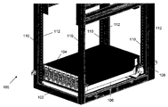
- FIG. 1 shows a data storage device in accordance with an embodiment of the present invention.
- Data storage device 100 comprises a rack 102 .
- a population set 104 is mounted on rack 102 , using rail assemblies 106 for isolating population set 104 from vibrations.
- Population set 104 comprises a plurality of disk drives. Typically, a population set comprises 60 to 200 disk drives. It will be apparent to one skilled in the art that the number of disk drives in population set 104 can vary, without deviating from the scope of the present invention.
- Population set 104 is mounted on rack 102 , using two rail assemblies 106 . The two rail assemblies 106 are placed on opposite faces of population set 104 .
- multiple population sets 104 can be mounted on rack 102 , each population set 104 having two rail assemblies 106 .
- the number of mounted population sets 104 depends on the data storage and data transfer requirements, system architecture and other practical limitations. In this case, the rail assemblies not only isolate the mounted population sets from the rack but also from each other.
- a metal strip 108 welded to population set 104 and rail assembly 106 , fastens population set 104 to rail assembly 106 .
- metal strip 108 has threaded holes such that screws can be inserted into these holes from within population set 104 and bolted to metal strip 108 . This arrangement locks population set 104 with rail assembly 106 into position. It may be apparent to anyone skilled in the art that other means for attaching population set 104 to rail assembly 106 may be used without deviating from the scope of the invention.
- Rack 102 comprises four vertical columns 110 to support a plurality of population sets 104 .
- Each column 110 includes holes 112 for attachment to rail assembly 106 .
- rail assembly 106 is bolted to rack 102 .
- the means of attachment should not be limited to bolting. It should be noted that there exist other means of attaching rail assembly 106 with the rack 102 without deviating from the scope of the invention.
- FIG. 2 shows a population set with a rail assembly in accordance with an embodiment of the present invention. Though only one rail assembly 106 is visible in FIG. 2 , it will be apparent to anyone skilled in the art that there is a second rail assembly on a side of population set 104 opposite to the side on which rail assembly 106 is attached. Both these rail assemblies isolate population set 104 from rack 102 .
- Population set 104 includes a plurality of removable and serviceable storage modules (RSMs) 202 , and related circuitry for delivering power and control to RSMs 202 .
- RSMs 202 and the related circuitry are contained in enclosure 204 .
- RSM 202 further includes a plurality of disk drives and related circuitry for delivering power and control to the disk drives.
- FIG. 3A shows a rail assembly for dampening vibrations in accordance with an embodiment of the present invention.
- FIG. 3B is an exploded view of the rail assembly in accordance with an embodiment of the present invention.
- Rail 302 of rail assembly 106 is made up of a hard metal or any other suitable material depending on the weight of population set 104 .
- rail 302 can be made up of 14-gauge electro-galvanized cold rolled steel.
- Rail 302 has a horizontal extension 304 from the lowermost surface, to support population set 104 .
- Each end of rail 302 has two holes 306 on the surface, to enable attachment to population set 104 .
- Rail assembly 106 and population set 104 can be attached by means of nuts and screws through holes 306 in rail assembly 106 , and holes 210 in population set 104 .
- the plurality of isolators of rail assembly 106 is attached to each end of rail 302 through bracket 308 , nuts 310 and lock washers 312 .
- the number of isolators can vary, depending on the number of disk drives in population set 104 .
- the plurality of isolators includes two vertically aligned isolators 314 with respect to bracket 308 ; and one sideways-aligned isolator 316 with respect to bracket 308 .
- Vertically aligned isolators 314 and sideways-aligned isolators 316 are made of different materials. These different materials serve different purposes. Sideways-aligned isolators 316 protect population set 104 from shock.
- Vertically aligned isolators 314 are for vibration dampening.
- the location of the isolators is such that two vertically aligned isolators 314 and one sideways-aligned isolator 316 are closest to the points of attachment of population set 104 to rail assembly 106 and the point of attachment of rack 102 to 5 rail assembly.
- commercially available grommets can be used as isolators.
- commercially available male-male sandwich mounts of the ISOLOSSTM grommet series manufactured by EAR Speciality Composites can be used as vertically aligned isolators 314 .
- mounting feet of the ISODAMPTM AND VERSADAMPTM series manufactured by EAR Speciality Composites can be used as sideways-aligned isolators 316 .
- Vertically aligned isolator 314 is fixed to rail 302 through bracket 308 , nut 310 and lock washer 312 .
- Sideways-aligned isolator 316 is bolted to bracket 308 directly.
- the surface of bracket 308 facing rack 102 , has two holes 318 to attach it to rack 102 .
- Rail assembly 106 and rack 102 can be connected by using nuts and screws through holes 318 in rail assembly 106 and holes 112 in population set 104 .
- the surface of bracket 308 facing population set 104 , has hole 320 to attach sideways-aligned isolator 316 .
- the top surface of bracket 308 has two holes 322 to attach vertically aligned isolator 314 .
- FIG. 4A is a side view of a vertically aligned isolator 314 in accordance with an embodiment of the present invention.
- FIG. 4B is a side view of a sideways-aligned isolator 316 in accordance with an embodiment of the present invention.
- the dimensions of holes 320 and 322 are suitable for attaching the plurality of isolators to bracket 308 .
- composition of formulating materials of the isolators may vary, depending on the number of disk drives in population set 104 and the amount of isolation required.
- the system of the invention is extensible in horizontal and vertical directions.
- Rack 102 is extensible in both vertical and horizontal directions.
- Rack 102 can be extended in the horizontal direction by increasing the number of columns 110 or by any other method.
- Rack 102 can be extended in the vertical direction by increasing the height of columns 110 or by any other method.
- the system of the invention can be suitably used with any four-post cabinet irrespective of the height, width or depth of the cabinet.
- two rail assemblies 106 are capable of isolating population sets 104 of different sizes. The size of population set 104 depends upon the number of disk drives it carries. Varying the number of disk drives results in change in the dimensions of population set 104 .
- rail 302 is attached to both rack 102 and population set 104 .
- Two brackets 308 to which the plurality of isolators is bolted, are not attached to rack 102 .
- the brackets 308 can slide on rail 302 . This configuration isolates varying sizes of population set 104 from vibrations at the same time.
- the present invention provides a system and method for the isolation of a mass storage device comprising a plurality of disk drives from both internal and external vibrations. This eliminates the need of protecting every individual disk drive from vibrations and shock.
- the present invention is suitable for use with a redundant array of independent disks (RAID) based rack-mount systems.
- RAID redundant array of independent disks
- Population set 104 is placed in an operational environment comprising computer servers, or is mounted on or within a mass storage device.
- the mass storage device can have a rack structure, cabinet structure, or any other supporting structure.
- the present invention isolates population set 104 from vibrations in such a way that the disk drives in the population set are packed with optimal density.
- the present invention enables replacement of individual disk drives from population set 104 without disturbing the other disk drives of the population set.
- the present invention is extensible in the horizontal and vertical direction, making it flexible for use in mass storage devices.
- a ‘system for optimal vibration isolation of disk drives in a data storage device’ can include any type of analysis, manual or automatic, to anticipate the needs of a disk drive or set of disk drives at a time of operation.
- the invention has been described primarily with respect to disk drives and other storage devices, aspects of the invention may be provide benefits in other any applications where there are vibration-sensitive devices.
- a ‘computer’ for purposes of embodiments of the present invention may include any processor-containing device, such as a mainframe computer, personal computer, laptop, notebook, microcomputer, server, personal data manager or ‘PIM’ (also referred to as a personal information manager), smart cellular or other phone, so-called smart card, set-top box, or any of the like.
- processor-containing device such as a mainframe computer, personal computer, laptop, notebook, microcomputer, server, personal data manager or ‘PIM’ (also referred to as a personal information manager), smart cellular or other phone, so-called smart card, set-top box, or any of the like.
Landscapes
- Engineering & Computer Science (AREA)
- Business, Economics & Management (AREA)
- Emergency Management (AREA)
- Computer Hardware Design (AREA)
- General Engineering & Computer Science (AREA)
- Microelectronics & Electronic Packaging (AREA)
- Vibration Prevention Devices (AREA)
Abstract
Description
Claims (4)
Priority Applications (1)
| Application Number | Priority Date | Filing Date | Title |
|---|---|---|---|
| US10/956,248 US7187543B2 (en) | 2004-09-30 | 2004-09-30 | System for optimal vibration isolation of disk drives in a data storage device |
Applications Claiming Priority (1)
| Application Number | Priority Date | Filing Date | Title |
|---|---|---|---|
| US10/956,248 US7187543B2 (en) | 2004-09-30 | 2004-09-30 | System for optimal vibration isolation of disk drives in a data storage device |
Publications (2)
| Publication Number | Publication Date |
|---|---|
| US20060067060A1 US20060067060A1 (en) | 2006-03-30 |
| US7187543B2 true US7187543B2 (en) | 2007-03-06 |
Family
ID=36098818
Family Applications (1)
| Application Number | Title | Priority Date | Filing Date |
|---|---|---|---|
| US10/956,248 Expired - Lifetime US7187543B2 (en) | 2004-09-30 | 2004-09-30 | System for optimal vibration isolation of disk drives in a data storage device |
Country Status (1)
| Country | Link |
|---|---|
| US (1) | US7187543B2 (en) |
Cited By (18)
| Publication number | Priority date | Publication date | Assignee | Title |
|---|---|---|---|---|
| US20090213491A1 (en) * | 2008-02-22 | 2009-08-27 | Western Digital Technologies, Inc. | Information storage device with a bridge controller and a plurality of electrically coupled conductive shields |
| US7701705B1 (en) | 2007-12-10 | 2010-04-20 | Western Digital Technologies, Inc. | Information storage device with sheet metal projections and elastomeric inserts |
| US8164849B1 (en) | 2007-12-10 | 2012-04-24 | Western Digital Technologies, Inc. | Information storage device with a conductive shield having free and forced heat convection configurations |
| US20120194046A1 (en) * | 2011-01-27 | 2012-08-02 | Hon Hai Precision Industry Co., Ltd. | Container data center |
| US8390952B1 (en) | 2008-02-22 | 2013-03-05 | Western Digital Technologies, Inc. | Information storage device having a conductive shield with a peripheral capacitive flange |
| US8462460B1 (en) | 2012-03-29 | 2013-06-11 | Western Digital Technologies, Inc. | Shock mount and retainer for a disk drive enclosure |
| CN103244804A (en) * | 2013-05-07 | 2013-08-14 | 西安石油大学 | Laptop hiding device |
| US8547658B1 (en) | 2012-10-18 | 2013-10-01 | Western Digital Technologies, Inc. | Data storage device enclosure enabling use of a common shock mount across different products |
| US8705201B2 (en) | 2011-12-20 | 2014-04-22 | Western Digital Technologies, Inc. | Information storage device with a damping insert sheet between a housing bay and a disk drive |
| US8901418B2 (en) | 2012-06-25 | 2014-12-02 | Panduit Corp. | Server cabinet |
| US8955927B2 (en) | 2010-11-11 | 2015-02-17 | Panduit Corp. | Equipment rail and bracket assembly |
| US8960451B2 (en) | 2012-07-13 | 2015-02-24 | International Business Machines Corporation | Ruggedizing large server storage frame |
| US9144175B2 (en) | 2012-06-25 | 2015-09-22 | Panduit Corp. | Electronics cabinet |
| US20160029508A1 (en) * | 2013-04-24 | 2016-01-28 | Hitachi Systems, Ltd. | Container-type data center |
| US9274571B2 (en) | 2014-04-30 | 2016-03-01 | HGST Netherlands B.V. | Segmented frame for a storage drive |
| US9360900B1 (en) | 2013-08-21 | 2016-06-07 | Western Digital Technologies, Inc. | Captivating shock mounts for data storage devices using retention clips |
| US9836097B2 (en) | 2014-09-10 | 2017-12-05 | Western Digital Technologies, Inc. | Storage drive and storage drive block |
| US9943003B2 (en) | 2012-06-25 | 2018-04-10 | Panduit Corp. | Electronics cabinet |
Families Citing this family (4)
| Publication number | Priority date | Publication date | Assignee | Title |
|---|---|---|---|---|
| US8459476B2 (en) * | 2006-01-11 | 2013-06-11 | Mohammad Ghassem Malekmadani | Audio / video isolation rack |
| US8240490B2 (en) * | 2006-01-11 | 2012-08-14 | Mohammad Ghassem Malekmadani | Anti-vibration rack, mount and feet for computer servers |
| CN102460579A (en) * | 2009-06-05 | 2012-05-16 | 齐拉泰克斯技术有限公司 | Apparatus for supporting a disk drive, disk drive test apparatus and method of testing a disk drive |
| US10861502B2 (en) * | 2017-12-26 | 2020-12-08 | Facebook, Inc. | Apparatus, system, and method for preventing shock-induced hard drive damage |
Citations (11)
| Publication number | Priority date | Publication date | Assignee | Title |
|---|---|---|---|---|
| US4713714A (en) * | 1985-11-26 | 1987-12-15 | Motorola Computer Systems, Inc. | Computer peripheral shock mount for limiting motion-induced errors |
| US5209356A (en) * | 1992-02-05 | 1993-05-11 | Chaffee Thomas M | Acoustic rack |
| US5858509A (en) * | 1996-11-15 | 1999-01-12 | Digital Equipment Corporation | Attenuating vibrations in a mounting shelf for multiple disk drives |
| US6056381A (en) * | 1993-05-07 | 2000-05-02 | Turner; Gary John | Vibration isolation platform |
| US6155660A (en) * | 1995-03-07 | 2000-12-05 | Rittal-Werk Rudolf Loh Gmbh & Co. Kg | Switchgear cabinet with a framework |
| US20010036399A1 (en) * | 2000-04-12 | 2001-11-01 | Notohardjono Budy D. | Modular and flexible service frame enclosure |
| US6578939B1 (en) * | 2000-10-26 | 2003-06-17 | Hewlett-Packard Development Company, L.P. | Universal sliding rail assembly for rack mounting computers |
| US6702124B2 (en) * | 2001-12-06 | 2004-03-09 | Hewlett-Packard Development Company, L.P. | Flat spring clip for tool-less slide installation |
| US20040120123A1 (en) * | 2002-12-20 | 2004-06-24 | Mayer David W. | Multi-configurable telecommunications rack mounting system and method incorporating same |
| US20040120106A1 (en) * | 2002-12-20 | 2004-06-24 | Searby Tom J | Transformable computer and system and method incorporating same |
| US6891727B2 (en) * | 2002-08-21 | 2005-05-10 | International Business Machines Corporation | Apparatus and system to mount a device to a rack |
-
2004
- 2004-09-30 US US10/956,248 patent/US7187543B2/en not_active Expired - Lifetime
Patent Citations (11)
| Publication number | Priority date | Publication date | Assignee | Title |
|---|---|---|---|---|
| US4713714A (en) * | 1985-11-26 | 1987-12-15 | Motorola Computer Systems, Inc. | Computer peripheral shock mount for limiting motion-induced errors |
| US5209356A (en) * | 1992-02-05 | 1993-05-11 | Chaffee Thomas M | Acoustic rack |
| US6056381A (en) * | 1993-05-07 | 2000-05-02 | Turner; Gary John | Vibration isolation platform |
| US6155660A (en) * | 1995-03-07 | 2000-12-05 | Rittal-Werk Rudolf Loh Gmbh & Co. Kg | Switchgear cabinet with a framework |
| US5858509A (en) * | 1996-11-15 | 1999-01-12 | Digital Equipment Corporation | Attenuating vibrations in a mounting shelf for multiple disk drives |
| US20010036399A1 (en) * | 2000-04-12 | 2001-11-01 | Notohardjono Budy D. | Modular and flexible service frame enclosure |
| US6578939B1 (en) * | 2000-10-26 | 2003-06-17 | Hewlett-Packard Development Company, L.P. | Universal sliding rail assembly for rack mounting computers |
| US6702124B2 (en) * | 2001-12-06 | 2004-03-09 | Hewlett-Packard Development Company, L.P. | Flat spring clip for tool-less slide installation |
| US6891727B2 (en) * | 2002-08-21 | 2005-05-10 | International Business Machines Corporation | Apparatus and system to mount a device to a rack |
| US20040120123A1 (en) * | 2002-12-20 | 2004-06-24 | Mayer David W. | Multi-configurable telecommunications rack mounting system and method incorporating same |
| US20040120106A1 (en) * | 2002-12-20 | 2004-06-24 | Searby Tom J | Transformable computer and system and method incorporating same |
Non-Patent Citations (1)
| Title |
|---|
| http://www.newport.com/semi/Products/Vibration<SUB>-</SUB>Isolation/product.asp?id=2990; NEWPORT/ Vibration Control/ Isolators/ Pneumatic Isolation; (C) 1996-2004, Newport Corporation pp. 1-8. |
Cited By (25)
| Publication number | Priority date | Publication date | Assignee | Title |
|---|---|---|---|---|
| US7701705B1 (en) | 2007-12-10 | 2010-04-20 | Western Digital Technologies, Inc. | Information storage device with sheet metal projections and elastomeric inserts |
| US8164849B1 (en) | 2007-12-10 | 2012-04-24 | Western Digital Technologies, Inc. | Information storage device with a conductive shield having free and forced heat convection configurations |
| US20090213491A1 (en) * | 2008-02-22 | 2009-08-27 | Western Digital Technologies, Inc. | Information storage device with a bridge controller and a plurality of electrically coupled conductive shields |
| US8004791B2 (en) | 2008-02-22 | 2011-08-23 | Western Digital Technologies, Inc. | Information storage device with a bridge controller and a plurality of electrically coupled conductive shields |
| US8390952B1 (en) | 2008-02-22 | 2013-03-05 | Western Digital Technologies, Inc. | Information storage device having a conductive shield with a peripheral capacitive flange |
| US8955927B2 (en) | 2010-11-11 | 2015-02-17 | Panduit Corp. | Equipment rail and bracket assembly |
| US20120194046A1 (en) * | 2011-01-27 | 2012-08-02 | Hon Hai Precision Industry Co., Ltd. | Container data center |
| US8322679B2 (en) * | 2011-01-27 | 2012-12-04 | Hon Hai Precision Industry Co., Ltd. | Container data center |
| US9036295B1 (en) | 2011-12-20 | 2015-05-19 | Western Digital Technologies, Inc. | Information storage device with a damping insert sheet between a housing bay and a disk drive |
| US8705201B2 (en) | 2011-12-20 | 2014-04-22 | Western Digital Technologies, Inc. | Information storage device with a damping insert sheet between a housing bay and a disk drive |
| US8462460B1 (en) | 2012-03-29 | 2013-06-11 | Western Digital Technologies, Inc. | Shock mount and retainer for a disk drive enclosure |
| US8901418B2 (en) | 2012-06-25 | 2014-12-02 | Panduit Corp. | Server cabinet |
| US9510471B2 (en) | 2012-06-25 | 2016-11-29 | Panduit Corp. | Electronics cabinet |
| US9943003B2 (en) | 2012-06-25 | 2018-04-10 | Panduit Corp. | Electronics cabinet |
| US9144175B2 (en) | 2012-06-25 | 2015-09-22 | Panduit Corp. | Electronics cabinet |
| US9648778B2 (en) | 2012-06-25 | 2017-05-09 | Panduit Corp. | Electronics cabinet |
| US8960451B2 (en) | 2012-07-13 | 2015-02-24 | International Business Machines Corporation | Ruggedizing large server storage frame |
| US8547658B1 (en) | 2012-10-18 | 2013-10-01 | Western Digital Technologies, Inc. | Data storage device enclosure enabling use of a common shock mount across different products |
| US20160029508A1 (en) * | 2013-04-24 | 2016-01-28 | Hitachi Systems, Ltd. | Container-type data center |
| US9572279B2 (en) * | 2013-04-24 | 2017-02-14 | Hitachi Systems, Ltd. | Container-type data center |
| CN103244804A (en) * | 2013-05-07 | 2013-08-14 | 西安石油大学 | Laptop hiding device |
| CN103244804B (en) * | 2013-05-07 | 2014-10-15 | 西安石油大学 | Laptop hiding device |
| US9360900B1 (en) | 2013-08-21 | 2016-06-07 | Western Digital Technologies, Inc. | Captivating shock mounts for data storage devices using retention clips |
| US9274571B2 (en) | 2014-04-30 | 2016-03-01 | HGST Netherlands B.V. | Segmented frame for a storage drive |
| US9836097B2 (en) | 2014-09-10 | 2017-12-05 | Western Digital Technologies, Inc. | Storage drive and storage drive block |
Also Published As
| Publication number | Publication date |
|---|---|
| US20060067060A1 (en) | 2006-03-30 |
Similar Documents
| Publication | Publication Date | Title |
|---|---|---|
| US7187543B2 (en) | System for optimal vibration isolation of disk drives in a data storage device | |
| EP0210497B1 (en) | Environment control enclosure for a disc drive isolation system | |
| US6249432B1 (en) | Vibration dampening system for removable hard disk drive carriers | |
| US7012805B2 (en) | Ruggedized host module | |
| US7251131B2 (en) | Ruggedized host module | |
| CN102947886B (en) | Damped Vibration in a Storage Device Test System | |
| US7990639B2 (en) | Mobile event data recorder with multiple orientation vibration isolation | |
| EP3525561B1 (en) | Modifiable rack post bracket | |
| US7684180B2 (en) | Computer system with vibration absorbing cage | |
| US6633481B2 (en) | Media drive vibration attenuation system and method | |
| US7092250B2 (en) | Vibration-proof removable module | |
| JPH04216389A (en) | Disk-file with separation mount | |
| US6275353B1 (en) | Housing for a disc drive having cantilevered base slot to reduce mechanical shock damage | |
| US6621694B2 (en) | Vibration tolerant electronic assembly and related methods | |
| US20030048607A1 (en) | Disk drive support apparatus and methods | |
| US6445587B1 (en) | Disk drive vibration/shock attenuation system and method | |
| CN202183071U (en) | Server chassis | |
| US6473298B1 (en) | Peripheral device storage system | |
| JPH09153277A (en) | Information recording / reproducing device | |
| CN212138127U (en) | Computer network information safety device | |
| US7468860B1 (en) | Hook and loop device applied to control shock and vibration of critical components | |
| KR200360854Y1 (en) | Digital video recorder having shock buffer | |
| CN207852316U (en) | A kind of hard-disk cartridge with vibration-damping function | |
| EP1758124A1 (en) | Disk drive unit | |
| CN105511567A (en) | Hard disk storage apparatus |
Legal Events
| Date | Code | Title | Description |
|---|---|---|---|
| AS | Assignment |
Owner name: COPAN SYSTEMS, INC., COLORADO Free format text: ASSIGNMENT OF ASSIGNORS INTEREST;ASSIGNOR:ZIMLIN, STEVE;REEL/FRAME:015897/0334 Effective date: 20040929 |
|
| STCF | Information on status: patent grant |
Free format text: PATENTED CASE |
|
| AS | Assignment |
Owner name: SILICON VALLEY BANK, CALIFORNIA Free format text: SECURITY AGREEMENT;ASSIGNORS:COPAN SYSTEMS, INC.;COPAN SYSTEMS EMEA (PTY) LIMITED;REEL/FRAME:022228/0408 Effective date: 20081024 Owner name: SILICON VALLEY BANK, CALIFORNIA Free format text: SECURITY AGREEMENT;ASSIGNOR:COPAN SYSTEMS, INC.;REEL/FRAME:022228/0601 Effective date: 20081024 |
|
| AS | Assignment |
Owner name: WESTBURY INVESTMENT PARTNERS SBIC, LP, NEW YORK Free format text: SECURITY AGREEMENT;ASSIGNOR:COPAN SYSTEMS, INC.;REEL/FRAME:022309/0579 Effective date: 20090209 |
|
| AS | Assignment |
Owner name: SILICON GRAPHICS INTERNATIONAL CORP.,CALIFORNIA Free format text: ASSIGNMENT OF ASSIGNORS INTEREST;ASSIGNOR:SILICON VALLEY BANK;REEL/FRAME:024351/0936 Effective date: 20100223 Owner name: SILICON GRAPHICS INTERNATIONAL CORP., CALIFORNIA Free format text: ASSIGNMENT OF ASSIGNORS INTEREST;ASSIGNOR:SILICON VALLEY BANK;REEL/FRAME:024351/0936 Effective date: 20100223 |
|
| REMI | Maintenance fee reminder mailed | ||
| FPAY | Fee payment |
Year of fee payment: 4 |
|
| SULP | Surcharge for late payment | ||
| SULP | Surcharge for late payment | ||
| AS | Assignment |
Owner name: SILICON VALLEY BANK, CALIFORNIA Free format text: RELEASE BY SECURED PARTY;ASSIGNOR:WESTBURY INVESTMENT PARTNERS SBIC, LP;REEL/FRAME:032276/0091 Effective date: 20100223 |
|
| FPAY | Fee payment |
Year of fee payment: 8 |
|
| AS | Assignment |
Owner name: RPX CORPORATION, CALIFORNIA Free format text: ASSIGNMENT OF ASSIGNORS INTEREST;ASSIGNOR:SILICON GRAPHICS INTERNATIONAL CORP.;REEL/FRAME:035409/0615 Effective date: 20150327 |
|
| AS | Assignment |
Owner name: JPMORGAN CHASE BANK, N.A., AS COLLATERAL AGENT, ILLINOIS Free format text: SECURITY AGREEMENT;ASSIGNORS:RPX CORPORATION;RPX CLEARINGHOUSE LLC;REEL/FRAME:038041/0001 Effective date: 20160226 Owner name: JPMORGAN CHASE BANK, N.A., AS COLLATERAL AGENT, IL Free format text: SECURITY AGREEMENT;ASSIGNORS:RPX CORPORATION;RPX CLEARINGHOUSE LLC;REEL/FRAME:038041/0001 Effective date: 20160226 |
|
| AS | Assignment |
Owner name: RPX CLEARINGHOUSE LLC, CALIFORNIA Free format text: RELEASE (REEL 038041 / FRAME 0001);ASSIGNOR:JPMORGAN CHASE BANK, N.A.;REEL/FRAME:044970/0030 Effective date: 20171222 Owner name: RPX CORPORATION, CALIFORNIA Free format text: RELEASE (REEL 038041 / FRAME 0001);ASSIGNOR:JPMORGAN CHASE BANK, N.A.;REEL/FRAME:044970/0030 Effective date: 20171222 |
|
| AS | Assignment |
Owner name: JEFFERIES FINANCE LLC, NEW YORK Free format text: SECURITY INTEREST;ASSIGNOR:RPX CORPORATION;REEL/FRAME:046486/0433 Effective date: 20180619 |
|
| MAFP | Maintenance fee payment |
Free format text: PAYMENT OF MAINTENANCE FEE, 12TH YEAR, LARGE ENTITY (ORIGINAL EVENT CODE: M1553); ENTITY STATUS OF PATENT OWNER: LARGE ENTITY Year of fee payment: 12 |
|
| AS | Assignment |
Owner name: BARINGS FINANCE LLC, AS COLLATERAL AGENT, NORTH CAROLINA Free format text: PATENT SECURITY AGREEMENT;ASSIGNORS:RPX CLEARINGHOUSE LLC;RPX CORPORATION;REEL/FRAME:054198/0029 Effective date: 20201023 Owner name: BARINGS FINANCE LLC, AS COLLATERAL AGENT, NORTH CAROLINA Free format text: PATENT SECURITY AGREEMENT;ASSIGNORS:RPX CLEARINGHOUSE LLC;RPX CORPORATION;REEL/FRAME:054244/0566 Effective date: 20200823 |
|
| AS | Assignment |
Owner name: RPX CORPORATION, CALIFORNIA Free format text: RELEASE BY SECURED PARTY;ASSIGNOR:JEFFERIES FINANCE LLC;REEL/FRAME:054486/0422 Effective date: 20201023 |
|
| AS | Assignment |
Owner name: RPX CORPORATION, CALIFORNIA Free format text: RELEASE OF LIEN ON PATENTS;ASSIGNOR:BARINGS FINANCE LLC;REEL/FRAME:068328/0278 Effective date: 20240802 |
|
| AS | Assignment |
Owner name: BARINGS FINANCE LLC, AS COLLATERAL AGENT, NORTH CAROLINA Free format text: PATENT SECURITY AGREEMENT;ASSIGNORS:RPX CORPORATION;RPX CLEARINGHOUSE LLC;REEL/FRAME:068328/0674 Effective date: 20240802 |