US7141210B2 - Apparatus and method for a nanocalorimeter for detecting chemical reactions - Google Patents
Apparatus and method for a nanocalorimeter for detecting chemical reactions Download PDFInfo
- Publication number
- US7141210B2 US7141210B2 US10/114,611 US11461102A US7141210B2 US 7141210 B2 US7141210 B2 US 7141210B2 US 11461102 A US11461102 A US 11461102A US 7141210 B2 US7141210 B2 US 7141210B2
- Authority
- US
- United States
- Prior art keywords
- thermal
- array according
- region
- nanocalorimeter
- nanocalorimeter array
- Prior art date
- Legal status (The legal status is an assumption and is not a legal conclusion. Google has not performed a legal analysis and makes no representation as to the accuracy of the status listed.)
- Expired - Lifetime, expires
Links
- 238000006243 chemical reaction Methods 0.000 title claims abstract description 85
- 238000000034 method Methods 0.000 title description 59
- 238000005259 measurement Methods 0.000 claims abstract description 97
- 238000011067 equilibration Methods 0.000 claims abstract description 57
- 238000002955 isolation Methods 0.000 claims abstract description 39
- 238000001514 detection method Methods 0.000 claims abstract description 30
- 239000000758 substrate Substances 0.000 claims abstract description 18
- 230000008859 change Effects 0.000 claims description 47
- 239000000463 material Substances 0.000 claims description 46
- 239000000126 substance Substances 0.000 claims description 24
- 229910021521 yttrium barium copper oxide Inorganic materials 0.000 claims description 11
- 229910021417 amorphous silicon Inorganic materials 0.000 claims description 10
- 238000002156 mixing Methods 0.000 claims description 10
- 238000000151 deposition Methods 0.000 claims description 8
- XHCLAFWTIXFWPH-UHFFFAOYSA-N [O-2].[O-2].[O-2].[O-2].[O-2].[V+5].[V+5] Chemical compound [O-2].[O-2].[O-2].[O-2].[O-2].[V+5].[V+5] XHCLAFWTIXFWPH-UHFFFAOYSA-N 0.000 claims description 6
- BTGZYWWSOPEHMM-UHFFFAOYSA-N [O].[Cu].[Y].[Ba] Chemical compound [O].[Cu].[Y].[Ba] BTGZYWWSOPEHMM-UHFFFAOYSA-N 0.000 claims description 6
- 238000005842 biochemical reaction Methods 0.000 claims description 6
- 229910001935 vanadium oxide Inorganic materials 0.000 claims description 6
- 239000003153 chemical reaction reagent Substances 0.000 claims description 3
- 229910052710 silicon Inorganic materials 0.000 claims description 3
- 239000010703 silicon Substances 0.000 claims description 3
- 229910000661 Mercury cadmium telluride Inorganic materials 0.000 claims 1
- MCMSPRNYOJJPIZ-UHFFFAOYSA-N cadmium;mercury;tellurium Chemical compound [Cd]=[Te]=[Hg] MCMSPRNYOJJPIZ-UHFFFAOYSA-N 0.000 claims 1
- 108090000623 proteins and genes Proteins 0.000 description 78
- 102000004169 proteins and genes Human genes 0.000 description 78
- 239000003446 ligand Substances 0.000 description 75
- 238000012360 testing method Methods 0.000 description 31
- 150000001875 compounds Chemical class 0.000 description 30
- 239000010408 film Substances 0.000 description 29
- 238000009739 binding Methods 0.000 description 18
- 238000004519 manufacturing process Methods 0.000 description 17
- 229910052782 aluminium Inorganic materials 0.000 description 15
- XAGFODPZIPBFFR-UHFFFAOYSA-N aluminium Chemical compound [Al] XAGFODPZIPBFFR-UHFFFAOYSA-N 0.000 description 14
- 238000001704 evaporation Methods 0.000 description 13
- 230000008020 evaporation Effects 0.000 description 13
- 239000010409 thin film Substances 0.000 description 13
- 239000003550 marker Substances 0.000 description 12
- 239000004033 plastic Substances 0.000 description 12
- 229920003023 plastic Polymers 0.000 description 12
- 238000003556 assay Methods 0.000 description 11
- 229910052802 copper Inorganic materials 0.000 description 10
- 239000010949 copper Substances 0.000 description 10
- RYGMFSIKBFXOCR-UHFFFAOYSA-N Copper Chemical compound [Cu] RYGMFSIKBFXOCR-UHFFFAOYSA-N 0.000 description 9
- 230000006870 function Effects 0.000 description 9
- 239000012620 biological material Substances 0.000 description 8
- 238000010586 diagram Methods 0.000 description 8
- 238000013537 high throughput screening Methods 0.000 description 8
- 230000033001 locomotion Effects 0.000 description 8
- 229910052751 metal Inorganic materials 0.000 description 8
- 239000002184 metal Substances 0.000 description 8
- 108090000765 processed proteins & peptides Proteins 0.000 description 8
- IAZDPXIOMUYVGZ-UHFFFAOYSA-N Dimethylsulphoxide Chemical compound CS(C)=O IAZDPXIOMUYVGZ-UHFFFAOYSA-N 0.000 description 7
- 238000007707 calorimetry Methods 0.000 description 7
- 239000003795 chemical substances by application Substances 0.000 description 7
- 230000008021 deposition Effects 0.000 description 7
- 239000000203 mixture Substances 0.000 description 7
- 102000004196 processed proteins & peptides Human genes 0.000 description 7
- 239000004696 Poly ether ether ketone Substances 0.000 description 6
- -1 PolyPhenylene Polymers 0.000 description 6
- 239000004020 conductor Substances 0.000 description 6
- 238000005516 engineering process Methods 0.000 description 6
- 239000003112 inhibitor Substances 0.000 description 6
- 239000012528 membrane Substances 0.000 description 6
- 102000039446 nucleic acids Human genes 0.000 description 6
- 108020004707 nucleic acids Proteins 0.000 description 6
- 150000007523 nucleic acids Chemical class 0.000 description 6
- 229920002530 polyetherether ketone Polymers 0.000 description 6
- 229920000642 polymer Polymers 0.000 description 6
- 239000002904 solvent Substances 0.000 description 6
- XLYOFNOQVPJJNP-UHFFFAOYSA-N water Substances O XLYOFNOQVPJJNP-UHFFFAOYSA-N 0.000 description 6
- 108090000790 Enzymes Proteins 0.000 description 5
- 102000004190 Enzymes Human genes 0.000 description 5
- 238000003491 array Methods 0.000 description 5
- 230000004071 biological effect Effects 0.000 description 5
- 238000003486 chemical etching Methods 0.000 description 5
- 238000011161 development Methods 0.000 description 5
- 239000012530 fluid Substances 0.000 description 5
- 150000002611 lead compounds Chemical class 0.000 description 5
- 238000001459 lithography Methods 0.000 description 5
- 238000004377 microelectronic Methods 0.000 description 5
- 238000012544 monitoring process Methods 0.000 description 5
- 239000012071 phase Substances 0.000 description 5
- 230000008569 process Effects 0.000 description 5
- 238000000746 purification Methods 0.000 description 5
- 238000004544 sputter deposition Methods 0.000 description 5
- XKRFYHLGVUSROY-UHFFFAOYSA-N Argon Chemical compound [Ar] XKRFYHLGVUSROY-UHFFFAOYSA-N 0.000 description 4
- 101001017516 Drosophila melanogaster Muscle segmentation homeobox Proteins 0.000 description 4
- 239000004642 Polyimide Substances 0.000 description 4
- 238000010017 direct printing Methods 0.000 description 4
- 239000011888 foil Substances 0.000 description 4
- 238000010438 heat treatment Methods 0.000 description 4
- 239000011159 matrix material Substances 0.000 description 4
- 229920001721 polyimide Polymers 0.000 description 4
- 238000000926 separation method Methods 0.000 description 4
- 238000012546 transfer Methods 0.000 description 4
- 230000001960 triggered effect Effects 0.000 description 4
- 229920002799 BoPET Polymers 0.000 description 3
- 238000000018 DNA microarray Methods 0.000 description 3
- PEDCQBHIVMGVHV-UHFFFAOYSA-N Glycerine Chemical compound OCC(O)CO PEDCQBHIVMGVHV-UHFFFAOYSA-N 0.000 description 3
- 229920000265 Polyparaphenylene Polymers 0.000 description 3
- UCKMPCXJQFINFW-UHFFFAOYSA-N Sulphide Chemical compound [S-2] UCKMPCXJQFINFW-UHFFFAOYSA-N 0.000 description 3
- 230000003321 amplification Effects 0.000 description 3
- 238000004458 analytical method Methods 0.000 description 3
- 239000012298 atmosphere Substances 0.000 description 3
- 238000001311 chemical methods and process Methods 0.000 description 3
- 230000007423 decrease Effects 0.000 description 3
- 238000013461 design Methods 0.000 description 3
- 201000010099 disease Diseases 0.000 description 3
- 208000037265 diseases, disorders, signs and symptoms Diseases 0.000 description 3
- 239000003814 drug Substances 0.000 description 3
- 238000007876 drug discovery Methods 0.000 description 3
- 239000007789 gas Substances 0.000 description 3
- 230000005661 hydrophobic surface Effects 0.000 description 3
- 239000012212 insulator Substances 0.000 description 3
- 239000007788 liquid Substances 0.000 description 3
- 238000003199 nucleic acid amplification method Methods 0.000 description 3
- 229920000728 polyester Polymers 0.000 description 3
- 108020003175 receptors Proteins 0.000 description 3
- 238000012216 screening Methods 0.000 description 3
- 238000003786 synthesis reaction Methods 0.000 description 3
- 229910052724 xenon Inorganic materials 0.000 description 3
- FHNFHKCVQCLJFQ-UHFFFAOYSA-N xenon atom Chemical compound [Xe] FHNFHKCVQCLJFQ-UHFFFAOYSA-N 0.000 description 3
- IJGRMHOSHXDMSA-UHFFFAOYSA-N Atomic nitrogen Chemical compound N#N IJGRMHOSHXDMSA-UHFFFAOYSA-N 0.000 description 2
- 241000243251 Hydra Species 0.000 description 2
- 108091034117 Oligonucleotide Proteins 0.000 description 2
- XUIMIQQOPSSXEZ-UHFFFAOYSA-N Silicon Chemical compound [Si] XUIMIQQOPSSXEZ-UHFFFAOYSA-N 0.000 description 2
- 239000004809 Teflon Substances 0.000 description 2
- 229920006362 Teflon® Polymers 0.000 description 2
- 238000010521 absorption reaction Methods 0.000 description 2
- 150000001413 amino acids Chemical class 0.000 description 2
- 229910052786 argon Inorganic materials 0.000 description 2
- 230000008901 benefit Effects 0.000 description 2
- 230000008827 biological function Effects 0.000 description 2
- 230000008236 biological pathway Effects 0.000 description 2
- 230000033228 biological regulation Effects 0.000 description 2
- 230000015572 biosynthetic process Effects 0.000 description 2
- 239000005515 coenzyme Substances 0.000 description 2
- 238000012864 cross contamination Methods 0.000 description 2
- 230000000694 effects Effects 0.000 description 2
- 239000000284 extract Substances 0.000 description 2
- 229920002313 fluoropolymer Polymers 0.000 description 2
- 239000011521 glass Substances 0.000 description 2
- 239000011810 insulating material Substances 0.000 description 2
- 230000010354 integration Effects 0.000 description 2
- QRXWMOHMRWLFEY-UHFFFAOYSA-N isoniazide Chemical compound NNC(=O)C1=CC=NC=C1 QRXWMOHMRWLFEY-UHFFFAOYSA-N 0.000 description 2
- 150000002632 lipids Chemical class 0.000 description 2
- 238000012986 modification Methods 0.000 description 2
- 230000004048 modification Effects 0.000 description 2
- 229920000052 poly(p-xylylene) Polymers 0.000 description 2
- 229920001184 polypeptide Polymers 0.000 description 2
- 230000003449 preventive effect Effects 0.000 description 2
- 230000004853 protein function Effects 0.000 description 2
- 238000005057 refrigeration Methods 0.000 description 2
- 230000035945 sensitivity Effects 0.000 description 2
- 239000010935 stainless steel Substances 0.000 description 2
- 229910001220 stainless steel Inorganic materials 0.000 description 2
- 238000003860 storage Methods 0.000 description 2
- 230000001225 therapeutic effect Effects 0.000 description 2
- 230000008646 thermal stress Effects 0.000 description 2
- 238000005406 washing Methods 0.000 description 2
- 229910001369 Brass Inorganic materials 0.000 description 1
- OKTJSMMVPCPJKN-UHFFFAOYSA-N Carbon Chemical compound [C] OKTJSMMVPCPJKN-UHFFFAOYSA-N 0.000 description 1
- 235000008733 Citrus aurantifolia Nutrition 0.000 description 1
- 102000053602 DNA Human genes 0.000 description 1
- 206010013710 Drug interaction Diseases 0.000 description 1
- 241000124008 Mammalia Species 0.000 description 1
- 108700020796 Oncogene Proteins 0.000 description 1
- 102000043276 Oncogene Human genes 0.000 description 1
- 239000004698 Polyethylene Substances 0.000 description 1
- 239000004743 Polypropylene Substances 0.000 description 1
- 108020004511 Recombinant DNA Proteins 0.000 description 1
- 229910052581 Si3N4 Inorganic materials 0.000 description 1
- VYPSYNLAJGMNEJ-UHFFFAOYSA-N Silicium dioxide Chemical compound O=[Si]=O VYPSYNLAJGMNEJ-UHFFFAOYSA-N 0.000 description 1
- 235000011941 Tilia x europaea Nutrition 0.000 description 1
- 108091023040 Transcription factor Proteins 0.000 description 1
- 102000040945 Transcription factor Human genes 0.000 description 1
- 102000044209 Tumor Suppressor Genes Human genes 0.000 description 1
- 108700025716 Tumor Suppressor Genes Proteins 0.000 description 1
- 241000251539 Vertebrata <Metazoa> Species 0.000 description 1
- JLCPHMBAVCMARE-UHFFFAOYSA-N [3-[[3-[[3-[[3-[[3-[[3-[[3-[[3-[[3-[[3-[[3-[[5-(2-amino-6-oxo-1H-purin-9-yl)-3-[[3-[[3-[[3-[[3-[[3-[[5-(2-amino-6-oxo-1H-purin-9-yl)-3-[[5-(2-amino-6-oxo-1H-purin-9-yl)-3-hydroxyoxolan-2-yl]methoxy-hydroxyphosphoryl]oxyoxolan-2-yl]methoxy-hydroxyphosphoryl]oxy-5-(5-methyl-2,4-dioxopyrimidin-1-yl)oxolan-2-yl]methoxy-hydroxyphosphoryl]oxy-5-(6-aminopurin-9-yl)oxolan-2-yl]methoxy-hydroxyphosphoryl]oxy-5-(6-aminopurin-9-yl)oxolan-2-yl]methoxy-hydroxyphosphoryl]oxy-5-(6-aminopurin-9-yl)oxolan-2-yl]methoxy-hydroxyphosphoryl]oxy-5-(6-aminopurin-9-yl)oxolan-2-yl]methoxy-hydroxyphosphoryl]oxyoxolan-2-yl]methoxy-hydroxyphosphoryl]oxy-5-(5-methyl-2,4-dioxopyrimidin-1-yl)oxolan-2-yl]methoxy-hydroxyphosphoryl]oxy-5-(4-amino-2-oxopyrimidin-1-yl)oxolan-2-yl]methoxy-hydroxyphosphoryl]oxy-5-(5-methyl-2,4-dioxopyrimidin-1-yl)oxolan-2-yl]methoxy-hydroxyphosphoryl]oxy-5-(5-methyl-2,4-dioxopyrimidin-1-yl)oxolan-2-yl]methoxy-hydroxyphosphoryl]oxy-5-(6-aminopurin-9-yl)oxolan-2-yl]methoxy-hydroxyphosphoryl]oxy-5-(6-aminopurin-9-yl)oxolan-2-yl]methoxy-hydroxyphosphoryl]oxy-5-(4-amino-2-oxopyrimidin-1-yl)oxolan-2-yl]methoxy-hydroxyphosphoryl]oxy-5-(4-amino-2-oxopyrimidin-1-yl)oxolan-2-yl]methoxy-hydroxyphosphoryl]oxy-5-(4-amino-2-oxopyrimidin-1-yl)oxolan-2-yl]methoxy-hydroxyphosphoryl]oxy-5-(6-aminopurin-9-yl)oxolan-2-yl]methoxy-hydroxyphosphoryl]oxy-5-(4-amino-2-oxopyrimidin-1-yl)oxolan-2-yl]methyl [5-(6-aminopurin-9-yl)-2-(hydroxymethyl)oxolan-3-yl] hydrogen phosphate Polymers Cc1cn(C2CC(OP(O)(=O)OCC3OC(CC3OP(O)(=O)OCC3OC(CC3O)n3cnc4c3nc(N)[nH]c4=O)n3cnc4c3nc(N)[nH]c4=O)C(COP(O)(=O)OC3CC(OC3COP(O)(=O)OC3CC(OC3COP(O)(=O)OC3CC(OC3COP(O)(=O)OC3CC(OC3COP(O)(=O)OC3CC(OC3COP(O)(=O)OC3CC(OC3COP(O)(=O)OC3CC(OC3COP(O)(=O)OC3CC(OC3COP(O)(=O)OC3CC(OC3COP(O)(=O)OC3CC(OC3COP(O)(=O)OC3CC(OC3COP(O)(=O)OC3CC(OC3COP(O)(=O)OC3CC(OC3COP(O)(=O)OC3CC(OC3COP(O)(=O)OC3CC(OC3COP(O)(=O)OC3CC(OC3COP(O)(=O)OC3CC(OC3CO)n3cnc4c(N)ncnc34)n3ccc(N)nc3=O)n3cnc4c(N)ncnc34)n3ccc(N)nc3=O)n3ccc(N)nc3=O)n3ccc(N)nc3=O)n3cnc4c(N)ncnc34)n3cnc4c(N)ncnc34)n3cc(C)c(=O)[nH]c3=O)n3cc(C)c(=O)[nH]c3=O)n3ccc(N)nc3=O)n3cc(C)c(=O)[nH]c3=O)n3cnc4c3nc(N)[nH]c4=O)n3cnc4c(N)ncnc34)n3cnc4c(N)ncnc34)n3cnc4c(N)ncnc34)n3cnc4c(N)ncnc34)O2)c(=O)[nH]c1=O JLCPHMBAVCMARE-UHFFFAOYSA-N 0.000 description 1
- GPYXTLGJENDVIX-UHFFFAOYSA-N [O-2].[V+5].[Si+4] Chemical compound [O-2].[V+5].[Si+4] GPYXTLGJENDVIX-UHFFFAOYSA-N 0.000 description 1
- 230000009471 action Effects 0.000 description 1
- 239000004964 aerogel Substances 0.000 description 1
- 239000003570 air Substances 0.000 description 1
- 125000003275 alpha amino acid group Chemical group 0.000 description 1
- 239000012491 analyte Substances 0.000 description 1
- 238000013459 approach Methods 0.000 description 1
- 238000011948 assay development Methods 0.000 description 1
- 238000000429 assembly Methods 0.000 description 1
- 230000000712 assembly Effects 0.000 description 1
- 239000011324 bead Substances 0.000 description 1
- 238000005452 bending Methods 0.000 description 1
- 230000009141 biological interaction Effects 0.000 description 1
- 239000010951 brass Substances 0.000 description 1
- 229910052799 carbon Inorganic materials 0.000 description 1
- 239000003054 catalyst Substances 0.000 description 1
- 230000019522 cellular metabolic process Effects 0.000 description 1
- 239000000919 ceramic Substances 0.000 description 1
- 238000012512 characterization method Methods 0.000 description 1
- 238000005234 chemical deposition Methods 0.000 description 1
- 239000003638 chemical reducing agent Substances 0.000 description 1
- 239000013611 chromosomal DNA Substances 0.000 description 1
- 239000011248 coating agent Substances 0.000 description 1
- 238000000576 coating method Methods 0.000 description 1
- 230000000052 comparative effect Effects 0.000 description 1
- 239000002131 composite material Substances 0.000 description 1
- 230000021615 conjugation Effects 0.000 description 1
- 238000010276 construction Methods 0.000 description 1
- 238000011109 contamination Methods 0.000 description 1
- 238000004320 controlled atmosphere Methods 0.000 description 1
- 239000013256 coordination polymer Substances 0.000 description 1
- 230000008878 coupling Effects 0.000 description 1
- 238000010168 coupling process Methods 0.000 description 1
- 238000005859 coupling reaction Methods 0.000 description 1
- 238000002425 crystallisation Methods 0.000 description 1
- 230000008025 crystallization Effects 0.000 description 1
- 238000000354 decomposition reaction Methods 0.000 description 1
- 239000003599 detergent Substances 0.000 description 1
- 229940000406 drug candidate Drugs 0.000 description 1
- 238000003487 electrochemical reaction Methods 0.000 description 1
- 239000003623 enhancer Substances 0.000 description 1
- 230000007613 environmental effect Effects 0.000 description 1
- 230000005284 excitation Effects 0.000 description 1
- 238000000855 fermentation Methods 0.000 description 1
- 230000004151 fermentation Effects 0.000 description 1
- 238000011049 filling Methods 0.000 description 1
- 239000004811 fluoropolymer Substances 0.000 description 1
- 239000000446 fuel Substances 0.000 description 1
- 150000004676 glycans Chemical class 0.000 description 1
- 239000005556 hormone Substances 0.000 description 1
- 229940088597 hormone Drugs 0.000 description 1
- 230000006872 improvement Effects 0.000 description 1
- 238000010348 incorporation Methods 0.000 description 1
- 238000011534 incubation Methods 0.000 description 1
- 230000003993 interaction Effects 0.000 description 1
- 239000004571 lime Substances 0.000 description 1
- 238000013507 mapping Methods 0.000 description 1
- 229910021645 metal ion Inorganic materials 0.000 description 1
- 150000002739 metals Chemical class 0.000 description 1
- 229930014626 natural product Natural products 0.000 description 1
- 150000004767 nitrides Chemical class 0.000 description 1
- 229910052757 nitrogen Inorganic materials 0.000 description 1
- 239000002773 nucleotide Substances 0.000 description 1
- 125000003729 nucleotide group Chemical group 0.000 description 1
- 229920001542 oligosaccharide Polymers 0.000 description 1
- 150000002482 oligosaccharides Chemical class 0.000 description 1
- 230000003287 optical effect Effects 0.000 description 1
- 239000007800 oxidant agent Substances 0.000 description 1
- 230000001991 pathophysiological effect Effects 0.000 description 1
- 230000000144 pharmacologic effect Effects 0.000 description 1
- 125000002467 phosphate group Chemical group [H]OP(=O)(O[H])O[*] 0.000 description 1
- 238000010672 photosynthesis Methods 0.000 description 1
- 230000029553 photosynthesis Effects 0.000 description 1
- 230000035790 physiological processes and functions Effects 0.000 description 1
- 239000002985 plastic film Substances 0.000 description 1
- 229920003223 poly(pyromellitimide-1,4-diphenyl ether) Polymers 0.000 description 1
- 229910021420 polycrystalline silicon Inorganic materials 0.000 description 1
- 229920000573 polyethylene Polymers 0.000 description 1
- 229920006254 polymer film Polymers 0.000 description 1
- 229920001155 polypropylene Polymers 0.000 description 1
- 229920001282 polysaccharide Polymers 0.000 description 1
- 239000005017 polysaccharide Substances 0.000 description 1
- 229920005591 polysilicon Polymers 0.000 description 1
- 229920001296 polysiloxane Polymers 0.000 description 1
- 238000002360 preparation method Methods 0.000 description 1
- 238000007639 printing Methods 0.000 description 1
- 238000012545 processing Methods 0.000 description 1
- 230000006916 protein interaction Effects 0.000 description 1
- 239000000376 reactant Substances 0.000 description 1
- 102000005962 receptors Human genes 0.000 description 1
- 238000011160 research Methods 0.000 description 1
- 150000003839 salts Chemical class 0.000 description 1
- 238000000646 scanning calorimetry Methods 0.000 description 1
- HQVNEWCFYHHQES-UHFFFAOYSA-N silicon nitride Chemical compound N12[Si]34N5[Si]62N3[Si]51N64 HQVNEWCFYHHQES-UHFFFAOYSA-N 0.000 description 1
- 229910052814 silicon oxide Inorganic materials 0.000 description 1
- 239000007787 solid Substances 0.000 description 1
- 239000007790 solid phase Substances 0.000 description 1
- 239000007921 spray Substances 0.000 description 1
- 125000001424 substituent group Chemical group 0.000 description 1
- 238000010897 surface acoustic wave method Methods 0.000 description 1
- 230000009897 systematic effect Effects 0.000 description 1
- 229940124597 therapeutic agent Drugs 0.000 description 1
- 238000004448 titration Methods 0.000 description 1
- 230000001052 transient effect Effects 0.000 description 1
- 238000010792 warming Methods 0.000 description 1
Images


Classifications
-
- B—PERFORMING OPERATIONS; TRANSPORTING
- B82—NANOTECHNOLOGY
- B82Y—SPECIFIC USES OR APPLICATIONS OF NANOSTRUCTURES; MEASUREMENT OR ANALYSIS OF NANOSTRUCTURES; MANUFACTURE OR TREATMENT OF NANOSTRUCTURES
- B82Y15/00—Nanotechnology for interacting, sensing or actuating, e.g. quantum dots as markers in protein assays or molecular motors
-
- G—PHYSICS
- G01—MEASURING; TESTING
- G01N—INVESTIGATING OR ANALYSING MATERIALS BY DETERMINING THEIR CHEMICAL OR PHYSICAL PROPERTIES
- G01N25/00—Investigating or analyzing materials by the use of thermal means
- G01N25/20—Investigating or analyzing materials by the use of thermal means by investigating the development of heat, i.e. calorimetry, e.g. by measuring specific heat, by measuring thermal conductivity
- G01N25/48—Investigating or analyzing materials by the use of thermal means by investigating the development of heat, i.e. calorimetry, e.g. by measuring specific heat, by measuring thermal conductivity on solution, sorption, or a chemical reaction not involving combustion or catalytic oxidation
- G01N25/4846—Investigating or analyzing materials by the use of thermal means by investigating the development of heat, i.e. calorimetry, e.g. by measuring specific heat, by measuring thermal conductivity on solution, sorption, or a chemical reaction not involving combustion or catalytic oxidation for a motionless, e.g. solid sample
- G01N25/4866—Investigating or analyzing materials by the use of thermal means by investigating the development of heat, i.e. calorimetry, e.g. by measuring specific heat, by measuring thermal conductivity on solution, sorption, or a chemical reaction not involving combustion or catalytic oxidation for a motionless, e.g. solid sample by using a differential method
-
- G—PHYSICS
- G01—MEASURING; TESTING
- G01N—INVESTIGATING OR ANALYSING MATERIALS BY DETERMINING THEIR CHEMICAL OR PHYSICAL PROPERTIES
- G01N25/00—Investigating or analyzing materials by the use of thermal means
- G01N25/20—Investigating or analyzing materials by the use of thermal means by investigating the development of heat, i.e. calorimetry, e.g. by measuring specific heat, by measuring thermal conductivity
- G01N25/48—Investigating or analyzing materials by the use of thermal means by investigating the development of heat, i.e. calorimetry, e.g. by measuring specific heat, by measuring thermal conductivity on solution, sorption, or a chemical reaction not involving combustion or catalytic oxidation
- G01N25/4846—Investigating or analyzing materials by the use of thermal means by investigating the development of heat, i.e. calorimetry, e.g. by measuring specific heat, by measuring thermal conductivity on solution, sorption, or a chemical reaction not involving combustion or catalytic oxidation for a motionless, e.g. solid sample
-
- Y—GENERAL TAGGING OF NEW TECHNOLOGICAL DEVELOPMENTS; GENERAL TAGGING OF CROSS-SECTIONAL TECHNOLOGIES SPANNING OVER SEVERAL SECTIONS OF THE IPC; TECHNICAL SUBJECTS COVERED BY FORMER USPC CROSS-REFERENCE ART COLLECTIONS [XRACs] AND DIGESTS
- Y10—TECHNICAL SUBJECTS COVERED BY FORMER USPC
- Y10S—TECHNICAL SUBJECTS COVERED BY FORMER USPC CROSS-REFERENCE ART COLLECTIONS [XRACs] AND DIGESTS
- Y10S977/00—Nanotechnology
- Y10S977/902—Specified use of nanostructure
- Y10S977/932—Specified use of nanostructure for electronic or optoelectronic application
- Y10S977/953—Detector using nanostructure
- Y10S977/957—Of chemical property or presence
-
- Y—GENERAL TAGGING OF NEW TECHNOLOGICAL DEVELOPMENTS; GENERAL TAGGING OF CROSS-SECTIONAL TECHNOLOGIES SPANNING OVER SEVERAL SECTIONS OF THE IPC; TECHNICAL SUBJECTS COVERED BY FORMER USPC CROSS-REFERENCE ART COLLECTIONS [XRACs] AND DIGESTS
- Y10—TECHNICAL SUBJECTS COVERED BY FORMER USPC
- Y10T—TECHNICAL SUBJECTS COVERED BY FORMER US CLASSIFICATION
- Y10T436/00—Chemistry: analytical and immunological testing
- Y10T436/25—Chemistry: analytical and immunological testing including sample preparation
- Y10T436/25625—Dilution
-
- Y—GENERAL TAGGING OF NEW TECHNOLOGICAL DEVELOPMENTS; GENERAL TAGGING OF CROSS-SECTIONAL TECHNOLOGIES SPANNING OVER SEVERAL SECTIONS OF THE IPC; TECHNICAL SUBJECTS COVERED BY FORMER USPC CROSS-REFERENCE ART COLLECTIONS [XRACs] AND DIGESTS
- Y10—TECHNICAL SUBJECTS COVERED BY FORMER USPC
- Y10T—TECHNICAL SUBJECTS COVERED BY FORMER US CLASSIFICATION
- Y10T436/00—Chemistry: analytical and immunological testing
- Y10T436/25—Chemistry: analytical and immunological testing including sample preparation
- Y10T436/2575—Volumetric liquid transfer
Definitions
- This invention relates generally to an apparatus and method for an improved nanocalorimeter, and more specifically, to a system and method for an improved nanocalorimeter for measuring the heat released or absorbed during chemical reactions.
- Calorimetry is used to measure enthalpic changes, including enthaplic changes arising from reactions, phase changes, changes in molecular conformation, temperature variations, and other variations of interest that may occur for a particular specimen.
- enthalpic changes including enthaplic changes arising from reactions, phase changes, changes in molecular conformation, temperature variations, and other variations of interest that may occur for a particular specimen.
- other thermodynamic variables may be deduced. For example, measurements of enthalpy as a function of temperature reveal the heat capacity of a specimen, and titrations of reacting components can be used to deduce the binding constant and effective stoichiometry for a reaction.
- Calorimetry measurements are useful in a broad variety of applications, including, for example, pharmaceuticals (drug discovery, decomposition reactions, crystallization measurements), biology (cell metabolism, drug interactions, fermentation, photosynthesis), catalysts (biological, organic, or inorganic), electrochemical reactions (such as in batteries or fuel cells), and polymer synthesis and characterization, to name a few.
- calorimetry measurements can be useful in the discovery and development of new chemicals and materials of many types, as well as in the monitoring of chemical processes.
- Standard calorimeters require relatively large samples (typically about 0.5 ml to 10 liters) and usually measure one sample at a time. As such, these systems cannot be used to measure very small samples, as might be desired for precious or highly reactive materials.
- standard calorimeters cannot be used effectively to monitor a large number of reactions of small sample size in parallel, as is required in order to perform studies using combinatorial chemistry techniques.
- the sample to be studied is precious, and it might not be acceptable to use the relatively large amount of material required by a standard microcalorimeter to perform only one measurement.
- a standard microcalorimeter such as those sold, for example, by MicroCal® Inc. (model VP-ITC) or Calorimetry Sciences Corporation® (model CSC4500)
- Performing a measurement in standard microcalorimeters requires about 1 ml of sample, which means that one would possibly be Faced with using a majority or all of the precious material for one or a small series of measurements. Tools that enable calorimetric measurements with much smaller sample sizes would be helpful in overcoming this limitation.
- a combinatorial library is a collection of chemical compounds which have been generated, by either chemical synthesis or biological synthesis, by combining a number of chemical “building blocks” as reagents.
- a combinatorial polypeptide library is formed by combining a set of amino acids in every possible way for a given compound length (i.e., the number of amino acids in a polypeptide compound). Millions of chemical compounds can theoretically be synthesized through such combinatorial mixing of chemical building blocks.
- a library Once a library has been constructed, it must be screened to identify compounds, which possess some kind of biological or pharmacological activity. For example, screening can be done with a specific biological compound, often referred to as a target, that participates in a known biological pathway or is involved in some regulation function.
- the library compounds that are found to react with the targets are candidates for affecting the biological activity of the target, and hence a candidate for a therapeutic agent.
- HTS high throughput screening
- a variety of measurement approaches has been used to screen combinatorial libraries for lead compounds, one of which is the inhibitor assay.
- a marker ligand often the natural ligand in a biological pathway, is identified that will bind well with the target protein molecule.
- the assay requires the chemical attachment of a fluorescent molecule to this marker ligand such that the fluorescent molecule does not affect the manner in which the marker ligand reacts with the target protein.
- the target protein is exposed to the test ligands in microtitre wells. After a time necessary for reaction of the test ligand to the target protein, the marker ligand is applied.
- the wells are rinsed such that non-reacted marker ligand is washed away.
- the test ligand blocks the active site of the target protein so the marker ligand cannot react and is washed away, while in cells where the target protein and test ligand have not reacted, the marker ligand reacts with the target protein and is not washed away.
- the inhibitor assay requires time and expense to develop the assay.
- the principal components that need development are discovering a marker ligand and attaching a fluorophore to the marker in a manner that does not affect its reaction with the target protein. Attaching the fluorescent marker can often take 3 months of development or more and cost $250 k or more once the marker ligand is identified.
- An assay method that avoids such assay development, such as measuring the heat of the reaction with calorimetry, would eliminate this cost and lime delay in the discovery process.
- Calorimetry measurements are commonly utilized in biophysical and biochemical studies to determine energy changes as indications of biochemical reactions in a media.
- Prior techniques for measurements include using electrodes, thermopiles, optical techniques, and microcalorimeters for measurements within a sampled media.
- ultra-miniature microcalorimeter devices that require very small volumes of sampled media for accurate detection and measuring of biochemical reactions on, or in close proximity to, the microcalorimeter and which can be applied in a manner to quickly measure large numbers of reactions such that it can be as efficient as assays such as inhibitor assays which can be used in HTS to screen perhaps 100,000 test ligands a day.
- a differential calorimeter that includes sample and reference cells, a thermal shield surrounding the cells, heating devices thermally coupled to the thermal shield and the cells, a temperature monitoring system, and a control system.
- the temperature monitoring system monitors the temperature of the shield, cell temperatures, and temperature differentials between the cells and the shield.
- the control system generates output signals for control of the heating devices, with a gain setting and scan rate selected by means of a user interface.
- Output control signals are functions of input temperature signals and the user-selected gain setting, as well as functions of input temperature signals and the user-selected scan rate using a mapping function stored in memory.
- CMOS complementary metal-oxide-semiconductor
- the chip fabricated using standard CMOS processes, includes a reference zone and a sample zone.
- the reference and sample zones may be at opposite ends of a suspended platform or may reside on separate platforms.
- Each zone is heated with an integrated polysilicon heater.
- a thermopile consisting of a succession of thermocouple junctions generates a voltage representing the temperature difference between the reference and sample zones.
- a calorimeter sensor apparatus utilizes microcantilevered spring elements for detecting thermal changes within a sample containing biomolecules which undergo chemical and biochemical reactions.
- the spring element includes a bimaterial layer of chemicals on a coated region on at least one surface of the microcantilever.
- the chemicals generate a differential thermal stress across the surface upon reaction of the chemicals with an analyte or biomolecules within the sample due to the heat of chemical reactions in the sample placed on the coated region.
- the thermal stress across the spring element surface creates mechanical bending of the microcantilever.
- the spring element has a low thermal mass to allow detection and measuring of heat transfers associated with chemical and biochemical reactions within a sample place on or near the coated region. Deflections of the cantilever are detected by a variety of detection techniques.
- a microcalorimeter includes a thin amorphous membrane anchored to a frame within an environmental chamber. Thermometers and heaters are placed on one side of a thermal conduction layer mounted on the central portion of the membrane. Samples are placed on two such membranes; each sample is heated and its individual heat capacity determined. The samples are then mixed by sandwiching the two microcalorimeters together to cause a binding reaction to occur. The amount of heat liberated during the reaction is measured to determine the enthalpy of binding.
- the nanocalorimeter array includes at least one thermal isolation region residing on a substrate.
- Each thermal isolation region includes at least one thermal equilibration region, within which resides a thermal measurement device connected to detection electronics.
- a method for detecting chemical reactions at low concentrations through the use of a nanocalorimeter. Drops of potentially reactive chemical solutions are deposited within a thermal equilibration region of the nanocalorimeter and the drops are then merged. Thermal change occurring within the merged drops is measured to identify chemical solutions which cause thermal change.
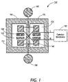
- FIG. 1 is a block diagram depicting components of a nanocalorimeter in accordance with one embodiment of the present invention
- FIG. 2 is a block diagram depicting components of a nanocalorimeter in accordance with another embodiment of the present invention.
- FIG. 3 is a block diagram depicting components of a nanocalorimeter in accordance with yet another embodiment of the present invention.
- FIG. 4 is a block diagram depicting components of a nanocalorimeter in accordance with yet another embodiment of the present invention.
- FIG. 5 is a diagram of the arrangement of the measurement thermometers and reference thermometers according to the present invention.
- FIG. 6 is an illustration of one method for merging of deposited drops according to the present invention.
- FIG. 7 is a schematic of the electronic measuring system in accordance with the system and method of the present invention.
- FIG. 8 is a block diagram depicting an array of components of a nanocalorimeter in accordance with another embodiment of the present invention.
- FIG. 9 is a cross-sectional diagram illustrating the operating environment of the nanocalorimeter in accordance with an embodiment of the present invention.
- FIG. 10 is a cross-sectional diagram illustrating one embodiment of the process flow of the nanocalorimeter in accordance with the present invention.
- ligand refers to an agent that binds a target molecule.
- the agent may bind the target protein when the target protein is in its native conformation, or when it is partially or totally unfolded or denatured.
- a ligand is not limited to an agent that binds a recognized functional region of the target protein e.g. the active site of an enzyme, the antigen-combining site of an antibody, the hormone-binding site of a receptor, a cofactor-binding site, and the like.
- a ligand can also be an agent that binds any surface or internal sequences or conformational domains of the target protein. Therefore, the ligands of the present invention encompass agents that in and of themselves may have no apparent biological function, beyond their ability to bind to the target protein in the manner described above.
- test ligand refers to an agent, comprising a compound, molecule or complex, which is being tested for its ability to bind to a target molecule.
- Test ligands can be virtually any agent, including without limitation metals, peptides, proteins, lipids, polysaccharides, nucleic acids, small organic molecules, and combinations thereof.
- Complex mixtures of substances such as natural product extracts, which may include more than one test ligand, can also be tested, and the component that binds the target molecule can be purified from the mixture in a subsequent step.
- target protein refers to a peptide, protein or protein complex for which identification of a ligand or binding partner is desired.
- Target proteins include without limitation peptides or proteins known or believed to be involved in the etiology of a given disease, condition or pathophysiological state, or in the regulation of physiological function.
- Target proteins may be derived from any living organism, such as a vertebrate, particularly a mammal and even more particularly a human. For use in the present invention, it is not necessary that the protein's biochemical function be specifically identified.
- Target proteins include without limitation receptors, enzymes, oncogene products, tumor suppressor gene products, vital proteins, and transcription factors, either in purified form or as part of a complex mixture of proteins and other compounds.
- target proteins may comprise wild type proteins, or, alternatively, mutant or variant proteins, including those with altered stability, activity, or other variant properties, or hybrid proteins to which foreign amino acid sequences, e.g. sequences that facilitate purification, have been added.
- test combination refers to the combination of a test ligand and a target protein.
- Control combination refers to the target protein in the absence of a test ligand.
- screening refers to the testing of a multiplicity of molecules or compounds for their ability to bind to a target molecule.
- the term “lead molecule” refers to a molecule or compound, from a combinatorial library, which displays relatively high affinity for a target molecule. High affinity is detected by this invention through the heat released in a chemical reaction.
- the terms “lead compound” and “lead molecule” are synonymous.
- target molecule encompasses peptides, proteins, nucleic-acids, and other receptors.
- the term encompasses both enzymes and proteins which are not enzymes.
- the term encompasses monomeric and multimeric proteins. Multimeric proteins may be homomeric or heteromeric.
- the term encompasses nucleic acids comprising at least two nucleotides, such as oligonucleotides. Nucleic acids can be single-stranded, double-stranded, or triple-stranded.
- the term encompasses a nucleic acid which is a synthetic oligonucleotide, a portion of a recombinant DNA molecule, or a portion of chromosomal DNA.
- target molecule also encompasses portions of peptides, secondary, tertiary, or quaternary structure through folding, with substituents including, but not limited to, cofactors, coenzymes, prosthetic groups, lipids, oligosaccharides, or phosphate groups.
- molecule refers to the compound, which is tested for binding affinity for the target molecule. This term encompasses chemical compounds of any structure, including, but not limited to nucleic acids and peptides. More specifically, the term “molecule” encompasses compounds in a compound or a combinatorial library. The terms “molecule” and “ligand” are synonymous.
- thermo change encompasses the release of energy in the form of heat or the absorption of energy in the form of heat.
- contacting a target molecule refers broadly to placing the target molecule in solution with the molecule to be screened for binding. Less broadly, contacting refers to the turning, swirling, shaking or vibrating of a solution of the target molecule and the molecule to be screened for binding. More specifically, contacting refers to the mixing of the target molecule with the molecule to be tested for binding. Mixing can be accomplished, for example, by repeated uptake and discharge through a pipette tip or by deposition by robotic means. Preferably, contacting refers to the equilibration of binding between the target molecule and the molecule to be tested for binding.
- biochemical conditions encompasses any component, thermodynamic property, or kinetic property of a physical, chemical, or biochemical reaction. Specifically, the term refers to conditions of temperature, pressure, protein concentration, pH, ionic strength, salt concentration, time, electric current, potential difference, and concentrations of cofactor, coenzyme, oxidizing agents, reducing agents, detergents, metal ion, ligands, buffer components, co-solvents including DMSO (dimethyl sulfoxide), glycerol, and related compounds, enhancers, and inhibitors.
- DMSO dimethyl sulfoxide
- glycerol glycerol
- the present invention encompasses nanocalorimeters and nanocalorimeter arrays that enable measurement of enthalpic changes, such as enthalpic changes arising from reactions, phase changes, changes in molecular conformation, and the like. Furthermore, the present invention encompasses combinatorial methods and high-throughput screening methods that use nanocalorimeters in the study, discovery, and development of new compounds, materials, chemistries, and chemical processes, as well as high-throughput monitoring of compounds or materials, or high-throughput monitoring of the processes used to synthesize or modify compounds or materials. The present invention also relates to compounds or materials identified by the above methods and their therapeutic uses (for diagnostic, preventive or treatment purposes), uses in purification and separation methods, and uses related to their novel physical or chemical properties. For the purposes herein, a nanocalorimeter refers to a device capable of measuring heats of reaction in the range of nanocalories.
- the present invention encompasses high-throughput screening methods for identifying a ligand that binds a target protein. If the target protein to which the test ligand binds is associated with or causative of a disease or condition, the ligand may be useful for diagnosing, preventing or treating the disease or condition.
- a ligand identified by the present method can also be one that is used in a purification or separation method, such as a method that results in purification or separation of the target protein from a mixture.
- the present invention also relates to ligands identified by the present method and their therapeutic uses (for diagnostic, preventive or treatment purposes) and uses in purification and separation methods.
- An important feature of the present invention is that it will detect any compound that binds to any sequence or domain of the target protein, not only to sequences or domains that are intimately involved in a biological activity or function.
- the binding sequence, region, or domain may be present on the surface of the target protein when it is in its folded state, or may be buried in the interior of the protein. Some binding sites may only become accessible to ligand binding when the protein is partially or totally unfolded.
- the test ligand is combined with a target protein, and the mixture is maintained under appropriate conditions and for a sufficient time to allow binding of the test ligand to the target protein.
- Experimental conditions are determined empirically for each target protein. When testing multiple test ligands, incubation conditions are usually chosen so that most ligand:target protein interactions would be expected to proceed to completion. In high-throughput screening applications, the test ligand is usually present in molar excess relative to the target protein.
- the target protein can be in a soluble form, or, alternatively, can be bound to a solid phase matrix.
- the matrix may comprise without limitation beads, membrane filters, plastic surfaces, or other suitable solid supports.
- Binding to a given protein is a prerequisite for pharmaceuticals intended to modify directly the action of that protein.
- a test ligand may indicate the potential ability of the test ligand to alter protein function and to be an effective pharmaceutical or lead compound for the development of such a pharmaceutical.
- the ligand may serve as the basis for the construction of hybrid compounds containing an additional component that has the potential to alter the protein's function.
- a known compound that inhibits the activity of a family of related enzymes may be rendered specific to one member of the family by conjugation of the known compound to a ligand, identified by the methods of the present invention, that binds specifically to that member at a different site than that recognized by the known compound.
- the present invention can be applied to large-scale systematic high-throughput procedures that allow a cost-effective screening of many thousands of test ligands.
- Once a ligand has been identified by the methods of the present invention it can be further analyzed in more detail using known methods specific to the particular target protein used. Also, the ligand can be tested for its ability to influence, either positively or negatively, a known biological activity of the target protein.
- FIG. 1 there is shown a plan view of one embodiment of detector 100 that is a part of the nanocalorimeter array in accordance with the present invention.
- This example embodiment enables a passive thermal equilibration of the combined protein, water and ligand drops with the device so that the resultant temperature changes can be detected by means of a temperature sensing device. Because the measurement region is kept small enough and sufficiently thermally conductive, through the fabrication of a thermally conducting layer such as aluminum or copper, the passive equilibration time can be made small.
- Suitable thermometer elements are based on thin film materials and include but are not limited to resistive thermometers, thermopiles and surface acoustic wave devices (SAW). The preferred embodiment is based on resistive thermometers made from thin film materials with a high temperature coefficient of resistivity, for example amorphous silicon, Vanadium Oxide and Yttrium Barium Copper Oxide (YBCO).
- Nanocalorimeter 100 includes thermal isolation layer 110 , which contains measurement region 160 and reference region 170 . Regions 160 and 170 may also be contained in separate isolation regions, as described hereinbelow. Thermal isolation region 110 provides isolation from surrounding thermal environments, thus increasing measurement time and reducing thermal noise. Although layer 110 is used in this example embodiment to thermally isolate the reaction and temperature sensing components of the nanocalorimeter 100 , any means to thermally isolate these components can be used in alternate embodiments of the present invention.
- the thermal isolation layer 110 may comprise a plastic material in thin foil form (typically ranging from less than 15 microns to approximately 25 microns in thickness for this embodiment, possibly as thin as 2 microns and as thick as 500 microns for some applications).
- plastic materials include polyimide (for example Dupont Kapton® and others), polyester (for example Dupont Mylar®) foil, PolyEtherEtherKetone (PEEK), or PolyPhenylene Sulphide (PPS).
- the thermal isolation region comprises other thin membranes of sufficiently low thermal conductivity, such as SiN and comparable materials.
- Measurement region 160 and reference region 170 include thermal equilibrium regions 120 and 125 respectively, that are thermally isolated from the detector's mechanical support.
- thermal equilibrium region 120 contains two resistive thermometers 140 , which measure the reaction temperature
- thermal equilibrium region 125 contains a second set of two thermometers 140 , which measure the variations in the background temperature.
- the resistive thermometers are deposited in thermal equilibrium regions 120 using standard fabrication techniques, including in embodiments, but not limited to, lithographic patterning of thin films, micro-electronic fabrication techniques (e.g. including sputtering, chemical etching, evaporation), and printed circuit board fabrication techniques.
- Both thermal equilibrium regions 120 and 125 are sufficiently large to receive and support separate drops of protein and ligand deposited by direct printing and also to support the combination of these two drops after merging, triggered by an example drop merging device 130 .
- the detector which includes the measurement and reference regions, may be 3.7 mm by 4.6 mm.
- Each thermal equilibration region 120 and 125 has a sufficient thermal conduction for the region to equilibrate quickly relative to the thermal dissipation.
- the regions have a sufficiently low heat capacity such that little of the heat of reaction is absorbed in the support.
- High thermal conductivity with low heat capacity may be accomplished, for example, with a metal film such as a 10 ⁇ m thick aluminum or copper film extending over the area of the thermal equilibration region.
- a metal film such as a 10 ⁇ m thick aluminum or copper film extending over the area of the thermal equilibration region.
- the film absorbs approximately 7% of the heat of reaction.
- the thermal equilibration regions must be thermally isolated from their environment so that the temperature difference caused by the reaction takes a relatively long time to dissipate.
- the longer this dissipation time the longer the signal can be integrated during measurement, which improves the signal to noise ratio.
- a 10 second integration time corresponds to a 0.1 Hz measurement bandwidth and increases the signal to noise ratio by 3.2 over a 1 second integration.
- Thermal dissipation occurs through four different channels: conduction across the supporting medium, conduction through the electrical interconnect, conduction through the surrounding environment and evaporation.
- the time constant increases with increases in the heat capacity of the drop and decreases with increases in the rate of thermal conduction. Note that while the heat capacity of the drop increases with drop size, increasing the drop size reduces the density of detectors on an array of detectors, increases the thermal equilibration time for the drop, and uses valuable material.
- a lower array density means a larger array size for a given detector number.
- drop size is 400 nL for the combined drop after merging.
- estimates of the time constants associated with different dissipation channels in the example embodiment are shown in the following table:
- the thermal isolation layer is 7 ⁇ m thick plastic and there are eleven interconnect leads with thickness of 0.1 ⁇ m for each thermal equilibrium region.
- the thermal isolation layer for this example embodiment may be fabricated of a plastic material in thin foil form (typically ranging from less than 15 microns to approximately 25 microns in thickness for this embodiment, possibly as thin as 2 microns and as thick as 500 microns for some applications), thereby ensuring that the above time constant for conduction across the thermal isolation layer is large compared with the measurement bandwidth.
- candidate plastic materials include polyimide (for example Dupont Kapton® and others), polyester (for example Dupont Mylar®) foil, PolyEtherEtherKetone (PEEK), PolyPhenylene Sulphide (PPS), polyethylene, or polypropylene.
- polyimide for example Dupont Kapton® and others
- polyester for example Dupont Mylar®
- PEEK PolyEtherEtherKetone
- PPS PolyPhenylene Sulphide
- polyethylene or polypropylene.
- the same material is; also used as the support for the thermal equilibration region, including the resistive thermometers.
- the same material may be used for the support and the thermal equilibration, including the resistive thermometers. Consequently, one important consideration in selecting a substrate polymer is the highest temperature that is needed in subsequent deposition and processing of thermometer, conductor and insulator films in the particular embodiment.
- the temperature needed in the deposition of amorphous silicon thermometer material is typically in the range of 170–250° C. This requires the selection of a substrate polymer film with a high softening temperature.
- These polymers may include, but are not limited to, polyimide (PI), PolyEtherEtherKetone (PEEK), or PolyPhenylene Sulphide (PPS).
- deposition of Vanadium Oxide thermometer material can be done at a substantially lower temperature. This allows the selection of substrate polymers with a lower softening point, such as Polyester (Dupont Mylar®).
- plastic substrates enable low cost manufacturing that can scale to large arrays of detectors, which enable fast and cost effective testing of large numbers of reactions.
- This invention anticipates, for example, detector array sizes of 96, 384, 1536 and larger.
- the low-cost detector arrays might also be used once and then discarded, eliminating time-consuming washing steps and reducing problems with cross-contamination.
- Another thermal consideration is the characteristic time for a drop to equilibrate with the detector after it is placed on the detector. This is a combination of the characteristic time for conduction of heat through the drop, t 1 , and the characteristic conduction time across the detector, t 2 .
- an aluminum film is used to increase the thermal conduction across the detector.
- the characteristic time for lateral conduction across the detector is governed by conduction across the metal film incorporated into the design for temperature equilibration, which is an aluminum strip in this example.
- the aluminum thickness is selected to provide sufficient thermal conduction without contributing significantly to the heat capacity of the detector.
- Heat capacity of the detector must be made sufficiently low so as to minimize the absorption of heat released from the reaction in the drop in order to minimize attenuation of the temperature change arising from the reaction.
- Each thermal equilibration region 120 and 125 contains thermometers 140 and drop merging electrodes 130 .
- thermometers 140 are shown spaced apart from more centrally-positioned drop merging electrodes 130 on each thermal equilibration region 120 and 125 , this configuration is for means of example only. Provided that the drop merging device 130 and thermometers 140 are in good thermal contact with the high conductance film, the exact placement of thermometers 140 and drop merging electrodes 130 is not important for thermal considerations.
- the two resistive thermometers 140 situated in thermal equilibration region 120 detect the heat of reaction between an arbitrary protein and a ligand at low concentrations deposited within thermal equilibration region 120 .
- the heat of reaction is detected through measurement of a voltage change in a bridge circuit due to the resistance change in the thermometers which are configured in the bridge circuit.
- Resistive thermometers 140 in thermal equilibrium region 120 detect a reaction between a sample ligand and a protein; the other resistive thermometers 145 in thermal equilibrium region 125 serve as a reference. Because the temperature rise due to the reaction may be small, for example approximately 10 ⁇ ° C. for protein and ligand concentrations of 1 ⁇ M and a heat of reaction of 10 4 cal/mol, the resistive thermometers 140 are fabricated from materials that provide a large change in resistance for a small temperature change.
- the resistive thermometers 140 are fabricated from materials with a high temperature coefficient of resistance, such as amorphous silicon Vanadium Oxide and Yttrium Barium Copper Oxide (YBCO). Similar small drops of non-reactive solution (for example water or mixtures of water and DMSO) and target protein, the control combination, are deposited close together in thermal equilibrium region 125 . Resistive thermometers 140 are configured as an AC bridge represented by AC generator 180 and ground 190 , discussed in more detail hereinbelow. At a specified time after the drops have reached thermal equilibrium, they are moved together to initiate the reaction. The movement operation creates sufficient mixing of the two drops in a time small compared to the measurement time.
- amorphous silicon Vanadium Oxide and Yttrium Barium Copper Oxide amorphous silicon Vanadium Oxide and Yttrium Barium Copper Oxide (YBCO).
- YBCO Yttrium Barium Copper Oxide
- the heat released by the protein-ligand reaction of the test combination causes a change in the resistance of the affected thermometers relative to the reference thermometers. This change in resistance causes the voltage at the: detection point to change from zero. This change is detected by sensitive, noise rejecting circuits such as a lock-in amplifier.
- nanocalorimeter 200 includes thermal isolation layer 210 , which contains thermal equilibrium region 220 .
- Thermal isolation region 210 provides isolation from surrounding thermal environments, thus increasing measurement time and reducing thermal noise.
- thermal equilibrium region 220 contains one resistive thermometer 240 , which measures the reaction temperature.
- the resistive thermometer is deposited in thermal equilibrium region 220 using standard fabrication techniques, including in embodiments, but not limited to, lithographic patterning of thin films, micro-electronic fabrication techniques (e.g. including sputtering, chemical etching, evaporation), and printed circuit board fabrication techniques.
- Thermal equilibrium region 220 is sufficiently large to receive and support separate drops of protein and ligand deposited by direct printing and also to support the combination of these two drops after merging, triggered by drop merging device 230 .
- Thermal equilibration region 220 has a sufficient thermal conduction for the region to equilibrate quickly relative to the thermal dissipation.
- the region also has a sufficiently low heat capacity such that little of the heat of reaction is absorbed in the support.
- High thermal conductivity with low heat capacity may be accomplished, for example, with a metal film such as a 10 ⁇ m thick aluminum or copper film.
- Thermal equilibration region 220 contains thermometer 240 and drop merging device 230 .
- thermometer 240 is shown spaced apart from more centrally-positioned drop merging device 230 on thermal equilibration region 220 , this configuration is for means of example only. Provided that the drop merging device 230 and thermometer 240 are in good thermal contact with the high conductance film, the exact placement of thermometer 240 and drop merging device 230 is not important for thermal considerations.
- the resistive thermometer 240 situated in thermal equilibration region 220 detects the heat of reaction between an arbitrary protein and a ligand at low concentrations deposited within thermal equilibration region 220 .
- the heat of reaction is detected through measurement of a voltage change in a bridge circuit due to the resistance change in the thermometer, which is configured in the bridge circuit.
- Resistive thermometer 240 in thermal equilibrium region 220 detects a reaction between a sample ligand and a protein. Because the temperature rise due to the reaction may be small, for example approximately 1 m° C. for this embodiment, resistive thermometer 240 is fabricated from materials that provide a large change in resistance for a small temperature change.
- resistive thermometer 240 is made of a material with a high temperature coefficient for resistance such as amorphous silicon, Vanadium Oxide and Yttrium Barium Copper Oxide (YBCO).
- Resistive thermometer 240 is configured as an AC bridge represented by detection electronics 250 , discussed in more detail hereinbelow.
- the other three legs of the AC bridge are made of low temperature coefficient resistors located on the amplifier printed circuit board.
- They are moved together to initiate the reaction. The movement operation creates sufficient mixing of the two drops in a time small compared to the measurement time.
- the heat released by the protein-ligand reaction of the test combination causes a change in the resistance of thermometer 240 .
- This change in resistance causes voltage at a detection point to change from zero. This change is detected by sensitive, noise rejecting circuits such as a lock-in amplifier.
- the resistance change of the thermometer may be measured by a direct DC resistance measurement.
- nanocalorimeter 300 includes thermal isolation layer 310 , which contains thermal equilibration region 320 .
- Thermal isolation region 310 provides isolation from surrounding thermal environments, thus increasing measurement time and reducing thermal noise.
- thermal equilibration region 320 contains two resistive thermometers 340 , which measure the reaction temperature.
- Each resistive thermometer is deposited in thermal equilibration region 320 using standard fabrication techniques, including in embodiments, but not limited to, lithographic patterning of thin films, micro-electronic fabrication techniques (e.g. including sputtering, chemical etching, evaporation), and printed circuit board fabrication techniques.
- Thermal equilibration region 320 is sufficiently large to receive and support separate drops of protein and ligand deposited by direct printing and also to support the combination of these two drops after merging, triggered by drop merging device 330 .
- Thermal equilibration region 320 has a sufficient thermal conduction for the region to equilibrate quickly relative to the thermal dissipation.
- the region also has a sufficiently low heat capacity such that little of the heat of reaction is absorbed in the support. High thermal conductivity with low heat capacity may be accomplished, for example, with a metal film such as a 10 ⁇ m thick aluminum or copper film.
- Thermal equilibration region 320 contains thermometers 340 and drop merging device 330 .
- thermometers 340 are shown spaced apart from more centrally-positioned drop merging device 330 on thermal equilibration region 320 , this configuration is for means of example only. Provided that the drop merging device 330 and thermometers 340 are in good thermal contact with the high conductance film, the exact placement of thermometers 340 and drop merging device 330 is not important for thermal considerations.
- two resistive thermometers 340 situated in thermal equilibration region 320 detect the heat of reaction between an arbitrary protein and a ligand at low concentrations deposited within thermal equilibration region 320 .
- the heat of reaction is detected through measurement of a voltage change in a bridge circuit due to the resistance change in the thermometers, which are configured in the bridge circuit.
- Resistive thermometer 340 in thermal equilibrium region 320 detects a reaction between a sample ligand and a protein. Because the temperature rise due to the reaction may be small, for example approximately 10 ⁇ ° C.
- resistive thermometers 340 are fabricated from materials that provide a large change in resistance for a small temperature change.
- resistive thermometers 340 are made of materials with a high temperature coefficient for resistance such as amorphous silicon. Vanadium Oxide and Yttrium Barium Copper Oxide (YBCO).
- Resistive thermometer 340 are configured as an AC bridge represented by detection electronics 350 , discussed in more detail hereinbelow.
- the other two legs of the AC bridge are made of low temperature coefficient resistors located on the amplifier printed circuit board.
- They are moved together to initiate the reaction.
- the movement operation creates sufficient mixing of the two drops in a time small compared to the measurement time.
- the heat released by the protein-ligand reaction of the test combination causes a change in the resistance of thermometers 340 .
- This change in resistance causes voltage at a detection point to change from zero. This change is detected by sensitive, noise rejecting circuits such as a Lock-in amplifier.
- the resistance change of the thermometer may be measured by direct DC resistance measurement of the two thermometers connected in series.
- nanocalorimeter 400 includes thermal isolation layers 410 , each of which contains a thermal equilibration region. Thermal isolation regions 410 provide isolation from surrounding thermal environments, thus increasing measurement time and reducing thermal noise.
- thermal equilibration regions 420 and 425 each contain two resistive thermometers 440 , which measure the reaction temperature. Each resistive thermometer is deposited in thermal equilibration regions 420 and 425 using standard fabrication techniques, including in embodiments, but not limited to, lithographic patterning of thin films, micro-electronic fabrication techniques (e.g. including sputtering, chemical etching, evaporation), and printed circuit board fabrication techniques.
- Thermal equilibration regions 420 and 425 are sufficiently large to receive and support separate drops of protein and ligand deposited by direct printing and also to support the combination of these two drops after merging, triggered by drop merging device 430 .
- Thermal equilibration regions 420 and 425 have a sufficient thermal conduction for the region to equilibrate quickly relative to the thermal dissipation.
- the regions also have a sufficiently low heat capacity such that little of the heat of reaction is absorbed in the support. High thermal conductivity with low heat capacity may be accomplished, for example, with a metal film such as a 10 ⁇ m thick aluminum or copper film.
- Thermal equilibration regions 420 and 425 contain thermometers 440 and drop merging devices 430 .
- thermometers 440 are shown spaced apart from more centrally-positioned drop merging device 430 on thermal equilibration regions 420 and 425 , this configuration is for means of example only. Provided that the drop merging devices 430 and thermometers 440 are in good thermal contact with the high conductance film, the exact placement of thermometers 440 and drop merging devices 430 is not important for thermal considerations.
- the two resistive thermometers 440 situated in thermal equilibration regions 420 and 425 detect the heat of reaction between an arbitrary protein and a ligand at low concentrations deposited within thermal equilibration regions 420 and 425 .
- the two resistive thermometers 440 situated in thermal equilibration region 425 detect the temperature of drops deposited and merged within thermal equilibration region 420 .
- the heat of reaction is detected through measurement of a voltage change in a bridge circuit due to the resistance change in the thermometers which are configured in the bridge circuit.
- Resistive thermometers 440 in thermal equilibration region 420 detect a reaction between a sample ligand and a protein; the other resistive thermometers 440 in thermal equilibration region 425 serve as a reference. Because the temperature rise due to the reaction may be small, for example approximately 10 ⁇ ° C. for protein and ligand concentrations of 1 ⁇ M and a heat of reaction of 10 4 cal/mol, the resistive thermometers 440 are fabricated from materials that provide a large change in resistance for a small temperature change. In this example embodiment, the resistive thermometers 440 are made of materials with a high temperature coefficient for resistance such as amorphous silicon, Vanadium Oxide, and Yttrium Barium Copper Oxide (YBCO). Similar small drops of non-reactive solution (for example water or mixtures of water and DMSO) and target protein, the control combination, are deposited close together in thermal equilibrium region 425 .
- non-reactive solution for example water or mixtures of water and DMSO
- Resistive thermometers 440 are configured as an AC bridge represented by AC generator 480 and ground 490 , discussed in more detail hereinbelow. At a specified time after the drops have reached thermal equilibrium, they are moved together to initiate the reaction. The movement operation creates sufficient mixing of the two drops in a time small compared to the measurement time. The heat released by the protein-ligand reaction of the test combination causes a change in the resistance of the affected thermometers. This change in resistance causes the voltage at the detection point to change from zero. This change is detected by sensitive, noise rejecting circuits, for example a lock-in amplifier.
- thermometers 510 , 520 , 530 and 540 form the four resistive legs of one example configuration for a bridge circuit according to the present invention. Resistive thermometers simultaneously measure temperature changes due to both the reaction and the background drift. In this example, two measurement thermometers 530 and 540 measure the reaction and two reference thermometers 510 and 520 measure the background temperature changes. If the resistance of the measurement thermometers changes, as happens when the temperature in the measurement region increases, then the voltage at point R in the bridge becomes more positive or negative relative to ground, depending on the polarity of the voltage placed across the bridge circuit and the sign of the thermal coefficient of resistance, while the voltage at point L in the bridge does the opposite, that is, becomes less positive or negative relative to ground, respectively.
- thermometer 540 has a low temperature sensitivity and is not fabricated on the device and where 520 is a variable resistor used to balance the bridge and is also not fabricated on the device.
- V S the signal voltage
- I the current through the resistor
- P power.
- B the measurement bandwidth in seconds
- R the resistance in Ohms
- k Boltzmann's constant.
- S/N 8.3 ⁇ 10 9 ⁇ T ⁇ square root over (P/B) ⁇ .
- Protein-ligand reactions are generally investigated at low concentrations during high-throughput screening, typically in the range of 10 ⁇ 5 to 10 ⁇ 6 M.
- the reactions typically release a heat of reaction, Q, which is on the order of 10 4 Cal/mole.
- Q heat of reaction
- For illustrative purposes, consider combining 2 drops with concentrations of 2 ⁇ M of protein and ligand, respectively. If the drops have equal volumes, the combination has a 1 ⁇ M concentration of each reactant. Additionally, CV ⁇ T MVQ, where V is the solution volume, C is the heat capacity of the solution, and M is the concentration in the mixed drop.
- thermometer impedance The following table provides the signal strength for various exemplary combinations of thermometer impedance and power:
- the deposited drops need to be merged together and the drop contents well mixed. It is noted that numerous methods for drop deposition are known in the art, any of which may operate beneficially with the present invention for the purpose of dispersing drops.
- this example drop merging method utilizes electrostatic forces generated by a planar configuration of two electrodes to merge the two drops and cause equilibration through fast mixing.
- the electrodes are constructed from thin conducting films on the surface of the device, using standard fabrication techniques, including in embodiments, but not limited to, lithographic patterning of thin films, micro-electronic fabrication techniques (e.g. including sputtering, chemical etching, evaporation), and printed circuit board fabrication techniques.
- the merging electrodes are formed from conducting film 620 and the conducting film 610 , which are positioned on the surface of substrate 650 and covered by insulating layer 640 .
- conducting films 610 and 620 may be approximately 1.0 mm by 0.8 mm in size, with a thickness ranging in size from approximately 0.1 ⁇ m to approximately 10 ⁇ m, and are separated by a gap of approximately 50 ⁇ m and are made of aluminum or copper thin film;
- the insulating layer may be approximately 0.1 ⁇ m to approximately 2 ⁇ m in thickness and may, for example, be made of silicon oxide or silicon nitride or silicon ox, nitride, or spin-, spray-, or otherwise deposited polymers, such as parylene, Dupont Teflon AF, 3M Fluorad products, 3M EGC 1700, other fluoropolymers, polysiloxanes, diamond-like carbon or other spin-coated, spray-coated, dip coated, or vapor
- Suitable insulator materials have a high electrical resistivity, chemical & mechanical durability and have no pinholes in deposited thin film form.
- high conductance film 680 that enables thermal equilibration in the thermal equilibration region.
- Protein drop 660 is deposited asymmetrically across the surface above conducting films 610 and 620 such that the drop disproportionately occupies the surface above one of the conducting films. In this example, 93% of protein drop 660 occupies the surface on the side of meridian 670 above conducting film 620 and 7% of protein drop 660 occupies the surface on the side of meridian 670 above conducting film 610 .
- Ligand drop 630 is deposited on the surface above conducting film 610 .
- a voltage is applied, preferably in the form of a voltage pulse, across conducting films 610 and 620 , drop 660 is propelled toward stationary drop 630 and the drops merge. While the comparative drop sizes of protein drop 660 and ligand drop 630 may be equal, unequal drop sizes may also be used.
- the hydrophobic surface of insulating layer 640 minimizes the adhesion of drops 630 and 660 to the surface, which reduces the drag on the drops during merging.
- the hydrophobic surface is made of a fluorinated polymer, such as, for example, 3M Fluorad, Dupont Teflon AF, 3M EGC-1700, or plasma-deposited fluorocarbons.
- a Parylene coating may be used as the insulator layer, as well as for the hydrophobic surface.
- thermometer material e.g. amorphous silicon
- the electrodes and thermometer may be fabricated in different layers, with the electrodes in a layer between the drop deposition points and the thermometer, to enable placing metal drop mover electrodes on top of the thermometers.
- an electrically insulating layer separates the thermometers and electrodes.
- Hydra Microdispensers made by Robbins Scientific, Sunnyvale, Calif.
- Robbins Scientific in their product information, “The barrels of 96 or 384 syringes are held in a fixed array centered along an X-Y grid that corresponds to the exact center of each well in a microplate.
- the plungers within the syringes move up and down under computer control, dispensing or aspirating liquids from microplates to the detector array.
- a precision motor assembly smoothly moves the plungers in increments of 2.5 microns.
- Cartesian Technologies provides a syringe-based system for delivering drops, wherein the Cartesian system utilizes syringe-syringe pump-solenoid assemblies to accurately aspirate and dispense drops from 20 nL to 250 ⁇ L, which is a range sufficient to satisfy the drop size requirement of the present embodiment.
- Packard BioSciences markets a system with piezoelectric-driven tips for aspirating liquids and delivering drops.
- the BioChip Arrayer product is a system with four dispensers (as compared with the full 96 or 384 of the Hydra Dispenser discussed above), and it delivers 300 nL in 2 seconds. If needed, several of these units may be used in parallel to satisfy the requirements of the present invention. Conversely, for embodiments with a much smaller numbers of samples, one unit may be sufficient.
- Pin spotting is a technology commonly used to place drops of solution onto slides in the DNA MicroArray industry. Pin spotting is often used for drops much smaller than 100–300 nL, as is common in the DNA MicroArray industry. However, there are some pin spotting technologies that can deliver drops with volumes in the range of 100 nL to 500 nL, as is preferred in an example embodiment of the present invention. For example, V&P Scientific sells pin spotting solutions for drops in this size range.
- FIG. 7 there is shown a schematic of one example embodiment of the electronic measuring system utilized herein.
- an alternating current (AC) detection method is illustrated.
- the AC detection method eliminates the 1/f noise inherent in electronic devices, particularly the a-Si thermometer, in which the 1/f noise can be significant at frequencies up to 1 kHz.
- a bridge circuit is used to detect changes in the resistance of the thermometers.
- the electronics implements four functions: amplification of the output of the bridge, zeroing of the bridge, detection of the signal, and computer analysis of the signal.
- a sine wave is provided by generator 780 . This sine wave drives the two input terminals of each bridge.
- Each bridge has two output terminals whose difference represents the temperature difference of the reference and measurement cells of the bridge.
- the signal on these two terminals is amplified by a low-noise signal amplifier 720 .
- the amplifiers must be located off the array, but amplifiers placed on the periphery result in the introduction of noise through the longer lead length.
- the amplifiers may be placed on a separate temperature-controlled heat sink positioned in close proximity to the detector array, with amplifiers 720 placed directly above the detector array and contacting the array through compressible pogo-pin connectors.
- a multiplexor 730 enables several individual detectors to use each lock-in amplifier and digitizer. With the embodiment of the invention shown in FIG. 7 , advantage is derived by the use of one amplifier for each detector and placement of the multiplexor 730 after the amplifier. The noise introduced by the multiplexor contributes a smaller relative amount than if the multiplexor had teen placed before the signal amplifier. Alternatively, if noise levels permit, the multiplexor could be placed before the signal amplifiers, allowing fewer signal amplifiers and a more compact arrangement of amplifiers and bridges.
- the temperature sensors in each bridge may be similar but not identical with each other. After temperature equilibration, the output of the bridge will not quite be zero because of these differences. The output will be a small sine-wave proportional to the difference.
- This common mode signal if not reduced, limits the amount of amplification between the bridge and the lock-in amplifier mixer. This in turn limits the system sensitivity.
- This common mode signal is minimized by use of the bridge zero operation that is performed after the initial amplification through second stage amplifier 740 through offset voltage 750 .
- a control signal selects a proportion of the sine-wave reference signal to be subtracted out of the amplified input signal. This control signal is set by measuring the output after equilibration and set its value to minimize the common mode output. If the inherent balance of the bridge is sufficient, then the offset amplifier is not needed.
- a lock-in operation 760 produces a dc output equal to the amplitude of the detector signal and may be implemented through known electronic circuitry.
- a standard lock-in amplifier known in the art contains an amplifier that increases input signal amplitude. The signal is then filtered by a bandpass filter with a center frequency the same as a reference sine-wave to remove noise at frequencies other than the reference frequency. A reference sine-wave is also input to the circuit. It is converted to a sine-wave and its phase is shifted to correspond to the phase of the input signal. The reference signal is then mixed with the input signal to create a composite output signal with a low-frequency component that represents the signal and a high-frequency component that represents the noise. A low-pass filter removes the high-frequency noise component.
- the lock-in operation could be implemented in software.
- the output of the lock-in operation is digitized by A-D converter 770 and input into computer 790 for analysis.
- the amplitude of this digitized signal represents the temperature difference on the bridge. After the drops are moved together and when a reaction occurs, its amplitude will increase until the drops are fully mixed and then decrease as heat is removed through conduction and evaporation. If no reaction occurs, no significant change will occur in the signal.
- the computer correlates the digitized signal against the expected temperature increase and decrease. If the correlation is positive, then the occurrence of a reaction is signaled.
- the detectors of the detector array are arranged in a rectilinear orientation to form a matrix array.
- the array is fabricated on thin plastic sheet 810 , for example a 10 ⁇ m thick Kapton® plastic substrate, and is supported by heat sink 820 , which is made of a material with a high thermal conductivity such as Cu or Al.
- Thin film conducting lines 850 placed in the regions between individual detectors 830 serve as electrical interconnect that carry signal and power between the detectors and the electronic module on the outside.
- Detectors 830 require interconnect for the signal excitation and the drop merging electrodes. All detectors in pairs of adjacent rows are connected to common merge-electrode power 880 .
- the resistive thermometers, drop merging electrodes, and electrical interconnect may be patterned on one side of the matrix array, and the thermal equilibration film may be fabricated on the other side.
- measurements are made simultaneously in two rows.
- Detector signal and ground are provided through contact pads located over the heat sink adjacent to each detector and connected to the array through detector amp contact pads 840 .
- Common bridge-excitation is provided for pairs of rows by bridge power conducting lines 870 . The merge-electrode power and common bridge-excitation are introduced through alternating rows.
- the detectors Because it is desirable to transfer fluids from standard storage devices, such as well-plates having different densities (96 well, 384 well, or 1536 well) the detectors have the same 9 mm square layout as standard 96 well-plates used in the biotechnology and pharmaceutical industries.
- FIG. 9 there is shown an example cross-section of the nanocalorimeter assembly and its detector environment, which provides thermal isolation, electrical connections and sample delivery.
- the three main heat transfer channels for the assembly include: thermal conduction through the air, thermal conduction across the supporting medium, and evaporation.
- measurements can be conducted at low temperatures and high humidities, for example 5° C. in near 100% relative humidity (preferably noncondensing), to reduce evaporation to acceptable limits.
- evaporation is controlled in part by maintaining near 100% relative humidity, within some acceptable tolerance, of the solvent used to dissolve the chemicals being investigated.
- the lower temperature reduces the vapor pressure of the solvent, and higher humidities reduce the concentration gradient of solvent in the gas phase near the surface of the drop, thereby reducing the driving force for evaporation.
- Thermal conductivity through the surrounding environment can be reduced in embodiments through use of a controlled atmosphere, for example an environment rich in Xenon or Argon, which have lower thermal conductivities than air.
- conductivity can also be controlled through the use of a partial or complete vacuum, aerogels or other insulating materials, and other methods that will occur to those skilled in the art.
- detector 910 resides on substrate 915 , which is supported by substrate carrier 925 , which is in contact with heat sink 920 .
- heat sink 920 is comprised of copper, but other materials known in the art could also be utilized.
- heat sink 920 may be in thermal contact with an optional active temperature control device 930 , which controls the temperature of the heat sink to within 1 m° C. to 0.1° C. of amplifier heat sink 940 .
- the detector amplifiers dissipate power (10 mW earth), which may be too much heat for the detector heat sink in some embodiments.
- the amplifier power can be sunk to a separate heat sink if desired.
- Signal amplifiers 990 reside on amplifier printed circuit board 950 , which is in contact with heat sink 940 .
- the temperature of heat sink 940 can be controlled by a temperature control device 960 , if desired for a particular embodiment.
- Pogo pin connectors 980 connect amplifier printed circuit board 950 with detector substrate 915 through amplifier pads 970 .
- the heat sink 920 does not need to be temperature controlled.
- the heat sink is thermally isolated from the enclosing chamber using standard low conduction materials like glass, plastic or stainless steel tubing.
- the Amplifier PCB 950 is placed in direct contact with the temperature controlled enclosing chamber.
- heat sink 920 may experience due to fluctuations of the chamber wall
- the heat capacity for various copper heat sinks corresponding to various array sizes is shown in the table below.
- all heat sinks are 3 cm in thickness.
- the heat sink area is shown below for the different examples, and the heat sink is assumed to be separated by 10 cm from the chamber walls, with Xenon gas at about 0.1 to 2 atm filling the space.
- Pogo pins contacting a 384-detector array is considered in the table below.
- Pogo-pin connector 980 materials for example brass, are selected for thermal performance.
- the power conducted per pin for a 0.1 C. temperature difference across the pin is shown in the following table along with the total power conducted for a 384-detector array (assuming three pins for each detector) for a 0.1° C. and a 0.1 m° C. temperature difference across the pin.
- a circular contact area with a diameter of 10 ⁇ m is assumed.
- the pogo pins may be the pointed-tip type.
- the temperature change during a 10 second measurement time is also shown.
- the temperature of amplifier printed circuit board 950 is accurately controlled in embodiments, either through active control or by thermal contact with the chamber wall.
- the values in Table 4 show that the temperature of the amplifier printed circuit board 950 must be controlled to within 0.01° C.
- active temperature control elements such as Peltier devices, a circulating-fluid refrigeration system, a heat pump, or any of a number of other active temperature-control devices known by those skilled in the art.
- thermal contact of the amplifier printed circuit board with the chamber wall is sufficient to limit ⁇ T to 13 ⁇ ° C.
- FIG. 10 illustrates a cross section of the measurement system utilizing the array described herein.
- the measurement system in this example configuration includes two compartments, load lock chamber 1010 and measurement chamber 1050 .
- the chambers and the atmosphere contained within them are equivalent; they are at the same operating temperature.
- the atmosphere within each chamber is a non-reactive gas, for example xenon, argon, air, or nitrogen, at a near 100% relative humidity for the solvents used in the drops being measured, and this humidity level is maintained through use of vapor pressure reservoirs 1045 .
- the temperature of the chamber walls is controlled to within 0.1° C.
- Heat sink 1085 receives heat from the power dissipated in the measurement thermometers on detector array 1040 when in the measurement chamber 1050 .
- thermometers In this example four thermometers are used for each detector, as shown in FIG. 1 , and each thermometer dissipates approximately 4 ⁇ W.
- the rate of temperature increase of the heat sink due to thermometer heating is approximately 10 ⁇ ° C. during a 10 second measurement, based on a 96 detector array and a heat sink with a heat capacity of 1500 J/° C. (refer to Table 3 above).
- Detector array 1040 is connected to detector array electronics 1030 which in turn are connected to system electronics 1060 .
- Biomaterials are contained within a biomaterial storage well plate 1015 , which is placed in the load lock chamber 1010 .
- In the measurement chamber 1050 are detector electronics 1075 as well as the associated heat sink/controller 1070 for the detector electronics.
- Biomaterials 1025 are deposited on the array with chemical deposition device 1035 in preparation for the measurement. While in the load lock chamber 1010 , the heat sink 1085 and associated detector 1040 and biomaterials 1025 are brought into thermal equilibrium with the chamber through heat conductor 1090 .
- Heat conductor 1090 may be any material or system of high thermal conductivity, and may be, for example, a metal block such as copper or aluminum that is in good thermal contact with both the chamber wall and the heat sink 1085 . As shown in FIG. 10 , thermal contact of heat conductor 1090 with heat sink 1085 occurs through the array transporter 1020 . However, this configuration is examplary only; other configurations will occur to those skilled in the art and are contemplated by the disclosure herein.
- heat conductor 1090 may have active temperature control, such as control by a circulating-fluid refrigeration or heating system, a Peltier device, a resistive heater, a heat pump, or any of a number of other active temperature-control devices known by those skilled in the art.
- the heat conductor and associated temperature control function can be integrated into the array transporter 1020 .
- Array transporter 1020 moves a detector array with deposited biomaterials from the load lock into measurement chamber 1050 and, in this example, utilizes a circular motion so that a detector array with measured materials is simultaneously moved from the measurement chamber to the load lock.
- Other array transport methods may be utilized, such as pick-and-place devices and belt devices with elevators.
- the detector array is raised into contact with the Pogo pins, and simultaneously the heat sink 1085 is raised above the transporter 1020 and thermally isolated from it by supporting pins 1053 .
- the supporting pins may be fabricated from any good thermal insulating material with sufficient mechanical strength, such as glass rods, stainless steel hollow tubing, plastic rods, porous ceramics, and other materials known to those skilled in the art.
- Other configurations are possible; for example, in alternative embodiments a temperature controller may be used to maintain heat sink 1085 at a specified temperature in measurement chamber 1050 , for example within 1 m° C. of the temperature of heat sink/controller 1070 of detector electronics 1075 , rather than relying on thermal isolation alone.
- Pogo pin detector connectors 1080 make electrical contact directly to the detectors to transmit thermal change information from the detector array to detector electronics 1075 .
- This type of connector is used in this example to provide a nonpermanent connection that allows connection to be made to successive arrays with low thermal contact to the array and good placement accuracy with a small foot-print that provides symmetrical contact to the measurement and reference regions to enable precise differential measurements.
- detector array 1040 In operation, detector array 1040 , whose initial temperature is within 1° C. of the temperature of load lock chamber 1010 , is placed in load lock chamber 1010 while a previously set-up detector array 1055 is being measured in measurement chamber 1050 .
- the proximity of measurement chamber 1050 to load lock chamber 1010 enables the connected detector array to be moved between the chambers while remaining in a controlled environment.
- Biomaterials are then moved into load lock chamber 1010 and stored in an appropriate vehicle 1015 , such as a 384 or 1536 well plate, although other containers or well plate sizes would also be appropriate.
- Biomaterials 1025 are then deposited on detector array 1040 using, for example, an aspirating/printing system or an automated syringe-type loader 1035 .
- Deposition device 1035 is maintained at a controlled temperature to avoid warming biomaterials 1025 .
- detector array 1040 is connected to detector array electronics 1030 and system electronics connector 1060 , which provides the necessary electrical connections to all the detector elements in detector array 1040 with the exception of the detector electronics for the measurement bridge.
- the detector bridges in detector array 1040 may be driven by the AC sine wave (for example, element 560 in FIG. 5 ) to self-heat to a temperature that equilibrates the drop temperature with the controlled environment in the load lock chamber. This signal is conducted through the system electronics connector 1060 to the detector array electronics 1030 .
- the detector array 1040 with deposited chemicals 1025 is then moved from load lock chamber 1010 to measurement chamber 1050 by array transporter 1020 and measured detector array 1055 is moved into load lock chamber 1010 .
- This movement may be accomplished through a rotation, such as a 180-degree rotation, or by any other means known in the art.
- the detector array is in thermal contact with heat sink 1085 , which in this embodiment is thermally isolated from transporter 1020 by supporting pins 1053 in measurement chamber 1050 .
- the measurement sequence is initiated by applying the AC-sine wave to the detector bridges.
- This signal is created by an AC generator located on the amplifier printed circuit board 1075 and conducted to detector array 1055 through the pogo pins 1080 .
- the detector bridge is then zeroed by properly setting the offset voltage. Thermal equilibration is confirmed by measuring the voltage across the detector bridge for a short period of time. When the rate of change: of this voltage is below a pre-specified level, the system is in thermal equilibrium. The zeroing operation may need to be repeated during this process.
- a row of drops of deposited chemicals 1025 is then merged and mixed on the surface of the detector array. This is accomplished by applying a drop moving voltage from the amplifier printed circuit board 1075 through the pogo pins 1080 to the detector array 1055 . The transient voltages generated from the merging voltages are allowed to dissipate. The reaction during mixing is then measured by detecting the imbalance in the bridge. Each bridge in the row is measured repeatedly for a period of time and the data is input into the computer for analysis.
- the individual bridges in a single row may be multiplexed in the detection electronics. A measurement is made on one detector and then the next detector in the row until all the detectors in the row have been measured. This is repeated for a period of time until all measurements for the row are complete. Alternatively, multiple instances of the detection electronics can simultaneously measure all the detector arrays in the row. To further reduce measurement time, measurements may be performed in blocks of two or more rows.
Landscapes
- Chemical & Material Sciences (AREA)
- Engineering & Computer Science (AREA)
- Health & Medical Sciences (AREA)
- General Health & Medical Sciences (AREA)
- Life Sciences & Earth Sciences (AREA)
- Biochemistry (AREA)
- Physics & Mathematics (AREA)
- Analytical Chemistry (AREA)
- Combustion & Propulsion (AREA)
- Chemical Kinetics & Catalysis (AREA)
- General Physics & Mathematics (AREA)
- Immunology (AREA)
- Pathology (AREA)
- Nanotechnology (AREA)
- Molecular Biology (AREA)
- Crystallography & Structural Chemistry (AREA)
- Investigating Or Analyzing Materials Using Thermal Means (AREA)
- Investigating Or Analysing Biological Materials (AREA)
Abstract
Description
Q=ΛAdT/dx,
where Λ is the thermal conductivity of the membrane, A is the cross section of the region through which the heat is conducted and dT/dx is the temperature gradient across the
T=T o e −ΛAt/CL,
where t is the time, L is the length of the
τ=CL/ΛA.
| TABLE 1 | ||
| Time | ||
| Conduction across thermal isolation layer + interconnect leads | 110 sec |
| Conduction through vapor (Xe) | 19 sec |
| Evaporation (5° C. operation) | 25 sec |
t 1=0.44R 2/α=0.61 sec,
where R is the drop radius, in this example 460 μm, and α is the thermal diffusivity of the drop, 0.0015 cm2/sec for water. For thin plastic substrates, the characteristic time for lateral conduction across the detector is governed by conduction across the metal film incorporated into the design for temperature equilibration, which is an aluminum strip in this example. An estimate for this characteristic time is
t 2=(ρC p V)drop ×L Al/4R drop ×δ×k Al=0.44 sec,
where ρ is the density of the drop, 1 g/cm3 in this example, CP is the specific heat, 1 cal/g° C. in this example, LAl is the length of the conduction path along the aluminum strip from one drop to the other, 2.5 Rdrop in this example, δ is the aluminum strip thickness, 10 μm in this example, and kAl is the aluminum thermal conductivity, 0.57 Cal/C-Cm-sec. The aluminum thickness is selected to provide sufficient thermal conduction without contributing significantly to the heat capacity of the detector. Heat capacity of the detector must be made sufficiently low so as to minimize the absorption of heat released from the reaction in the drop in order to minimize attenuation of the temperature change arising from the reaction.
α=1/R ΔR/ΔT,
it follows that
ΔR=αRΔT,
where R is resistance, T is temperature, and α is the thermal coefficient of resistance of the thermometer material. Therefore, the signal voltage across the resistor varies by
where VS is the signal voltage, I is the current through the resistor, and P is power. The thermal noise in each resistor becomes
V N=√{square root over (4kTRB)}=1.2×10⁻¹⁰ √{square root over (RB)}
where B is the measurement bandwidth in seconds, R is the resistance in Ohms, and k is Boltzmann's constant. Assuming the detection system can be constructed without introducing noise in excess of the thermal noise, the signal to noise ratio becomes
S/N=8.3×109 αΔT√{square root over (P/B)}.
CVΔT=MVQ,
where V is the solution volume, C is the heat capacity of the solution, and M is the concentration in the mixed drop. Therefore,
ΔT=MQ/C=10−6 mole/L×104 Cal/mole/103 Cal/° C.−L=10−5° C.,
where Q is the heat of reaction, C is the heat capacity of the solute, and M is the concentration in the mixed drop.
ΔV S=2ΔRI=2αΔTRI=4×10⁻⁷ RI=4×10⁻⁷ √{square root over (PR)}.
| TABLE 2 | |||||
| Thermometer | Detection | ||||
| Power | Impedance | Voltage | S: |
||
| 1 |
100 kΩ | 126 nV | 7:1 | ||
| 1 |
1 MΩ | 400 nV | 7:1 | ||
| 4 |
100 kΩ | 252 nV | 15:1 | ||
| 4 |
1 MΩ | 800 nV | 15:1 | ||
| TABLE 3 | |||||
| Well | Array | Array | Heat | Sink | Time |
| Number | Design | Size | Capacity | Area | Constant |
| 96 | 12 × 8 | 14.8 cm × 11.2 cm | 1500 J/C | 485 | 515000 cm |
| cm2 | |||||
| 384 | 24 × 16 | 25.6 cm × 19.4 cm | 4500 J/C | 1263 | 594000 cm |
| cm2 | |||||
| 1536 | 48 × 32 | 47.2 cm × 32.8 cm | 14000 J/C | 2030 | 1150000 cm |
| cm2 | |||||
| TABLE 4 | ||||||
| Power/Pin | Total Power | AT in 10 sec | Total | ΔT in 10 sec | ||
| (0.1 C control) | (0.1 C control) | (0.1 C control) | (0.1 mC control) | (0.1 mC control) | ||
| 1.2 cm pin | 49.2 μW | 56.6 mW | 0.13 mC | 56.6 μW | 0.13 μC |
| 0.56 cm pin | 47.7 μW | 54.9 mW | 0.12 mC | 54.9 μW | 0.12 μC |
Claims (28)
Priority Applications (10)
| Application Number | Priority Date | Filing Date | Title |
|---|---|---|---|
| US10/114,611 US7141210B2 (en) | 2002-04-01 | 2002-04-01 | Apparatus and method for a nanocalorimeter for detecting chemical reactions |
| US10/303,500 US7521253B2 (en) | 2002-04-01 | 2002-11-22 | Method for multiple target assay for drug discovery |
| US10/303,446 US20030186454A1 (en) | 2002-04-01 | 2002-11-22 | Apparatus and method for lead profiling assay |
| JP2003097637A JP4290460B2 (en) | 2002-04-01 | 2003-04-01 | Nanocalorimeter for detecting chemical reactions |
| EP03007357A EP1351052B1 (en) | 2002-04-01 | 2003-04-01 | Nanocalorimeter apparatus and method for detecting chemical reactions |
| US11/149,632 US7727768B2 (en) | 2002-04-01 | 2005-06-10 | Method for a nanocalorimeter for detecting chemical reactions |
| US11/167,612 US7833800B2 (en) | 2002-04-01 | 2005-06-27 | Thermal sensing with bridge circuitry |
| US11/167,635 US7754492B2 (en) | 2002-04-01 | 2005-06-27 | Thermal sensing device |
| US11/167,746 US7473030B2 (en) | 2002-04-01 | 2005-06-27 | Thermal sensing |
| US11/167,748 US7473031B2 (en) | 2002-04-01 | 2005-06-27 | Resistive thermal sensing |
Applications Claiming Priority (1)
| Application Number | Priority Date | Filing Date | Title |
|---|---|---|---|
| US10/114,611 US7141210B2 (en) | 2002-04-01 | 2002-04-01 | Apparatus and method for a nanocalorimeter for detecting chemical reactions |
Related Parent Applications (1)
| Application Number | Title | Priority Date | Filing Date |
|---|---|---|---|
| US10/303,446 Continuation-In-Part US20030186454A1 (en) | 2002-04-01 | 2002-11-22 | Apparatus and method for lead profiling assay |
Related Child Applications (7)
| Application Number | Title | Priority Date | Filing Date |
|---|---|---|---|
| US10/303,446 Continuation-In-Part US20030186454A1 (en) | 2002-04-01 | 2002-11-22 | Apparatus and method for lead profiling assay |
| US10/303,500 Continuation-In-Part US7521253B2 (en) | 2002-04-01 | 2002-11-22 | Method for multiple target assay for drug discovery |
| US11/149,632 Division US7727768B2 (en) | 2002-04-01 | 2005-06-10 | Method for a nanocalorimeter for detecting chemical reactions |
| US11/167,635 Continuation-In-Part US7754492B2 (en) | 2002-04-01 | 2005-06-27 | Thermal sensing device |
| US11/167,748 Continuation-In-Part US7473031B2 (en) | 2002-04-01 | 2005-06-27 | Resistive thermal sensing |
| US11/167,612 Continuation-In-Part US7833800B2 (en) | 2002-04-01 | 2005-06-27 | Thermal sensing with bridge circuitry |
| US11/167,746 Continuation-In-Part US7473030B2 (en) | 2002-04-01 | 2005-06-27 | Thermal sensing |
Publications (2)
| Publication Number | Publication Date |
|---|---|
| US20030186453A1 US20030186453A1 (en) | 2003-10-02 |
| US7141210B2 true US7141210B2 (en) | 2006-11-28 |
Family
ID=28041047
Family Applications (4)
| Application Number | Title | Priority Date | Filing Date |
|---|---|---|---|
| US10/114,611 Expired - Lifetime US7141210B2 (en) | 2002-04-01 | 2002-04-01 | Apparatus and method for a nanocalorimeter for detecting chemical reactions |
| US10/303,446 Abandoned US20030186454A1 (en) | 2002-04-01 | 2002-11-22 | Apparatus and method for lead profiling assay |
| US10/303,500 Expired - Lifetime US7521253B2 (en) | 2002-04-01 | 2002-11-22 | Method for multiple target assay for drug discovery |
| US11/149,632 Expired - Fee Related US7727768B2 (en) | 2002-04-01 | 2005-06-10 | Method for a nanocalorimeter for detecting chemical reactions |
Family Applications After (3)
| Application Number | Title | Priority Date | Filing Date |
|---|---|---|---|
| US10/303,446 Abandoned US20030186454A1 (en) | 2002-04-01 | 2002-11-22 | Apparatus and method for lead profiling assay |
| US10/303,500 Expired - Lifetime US7521253B2 (en) | 2002-04-01 | 2002-11-22 | Method for multiple target assay for drug discovery |
| US11/149,632 Expired - Fee Related US7727768B2 (en) | 2002-04-01 | 2005-06-10 | Method for a nanocalorimeter for detecting chemical reactions |
Country Status (3)
| Country | Link |
|---|---|
| US (4) | US7141210B2 (en) |
| EP (1) | EP1351052B1 (en) |
| JP (1) | JP4290460B2 (en) |
Cited By (41)
| Publication number | Priority date | Publication date | Assignee | Title |
|---|---|---|---|---|
| US20030186455A1 (en) * | 2002-04-01 | 2003-10-02 | Xerox Corporation | Apparatus and method for multiple target assay for drug discovery |
| WO2004097373A2 (en) * | 2003-04-28 | 2004-11-11 | Univ Arizona | Thermoelectric biosensor for analytes in a gas |
| US20050238080A1 (en) * | 2002-04-01 | 2005-10-27 | Palo Alto Research Center Incorporated | Resistive thermal sensing |
| US20050254552A1 (en) * | 2002-04-01 | 2005-11-17 | Palo Alto Research Center Incorporated | Thermal sensing |
| US20050254994A1 (en) * | 2002-04-01 | 2005-11-17 | Palo Alto Research Center Incorporated | Thermal sensing with bridge circuitry |
| US20050265898A1 (en) * | 2002-04-01 | 2005-12-01 | Palo Alto Research Center Incorporated | Thermal sensing |
| US20060133960A1 (en) * | 2003-04-28 | 2006-06-22 | Ahmad Lubna M | Thermoelectric sensor for analytes in a gas |
| US20070148416A1 (en) * | 2005-12-27 | 2007-06-28 | Palo Alto Research Center Incorporated | Layered structures on thin substrates |
| US20070147473A1 (en) * | 2005-12-27 | 2007-06-28 | Palo Alto Research Center Incorporated | Producing layered structures using printing |
| US20070145362A1 (en) * | 2005-12-27 | 2007-06-28 | Palo Alto Research Center Incorporated | Passive electronic devices |
| US20080053194A1 (en) * | 2003-04-28 | 2008-03-06 | Ahmad Lubna M | Thermoelectric sensor for analytes in a gas and related method |
| US20080053193A1 (en) * | 2003-04-28 | 2008-03-06 | Ahmad Lubna M | Thermoelectric sensor for analytes in a gas and related method |
| US7427844B2 (en) * | 2003-07-09 | 2008-09-23 | A. O. Smith Corporation | Switch assembly, electric machine having the switch assembly, and method of controlling the same |
| EP2000796A2 (en) | 2007-06-08 | 2008-12-10 | Palo Alto Research Center Incorporated | Ranking fragment types with calorimetry |
| EP2090354A2 (en) | 2008-02-14 | 2009-08-19 | Palo Alto Research Center Incorporated | Enhanced drop mixing using magnetic actuation |
| US20090260425A1 (en) * | 2003-12-18 | 2009-10-22 | Palo Alto Research Center Incorporated | Osmotic reaction detector for monitoring biological and non-biological reactions |
| US20090320573A1 (en) * | 2003-12-18 | 2009-12-31 | Xerox Corporation | Osmotic reaction detector for monitoring biological and non-biological reactions |
| DE102009014618A1 (en) * | 2009-03-24 | 2010-08-19 | Siemens Aktiengesellschaft | Heat conductivity detector for gas analyzer, has parylene layer that is formed in detector, and electrically heatable heater filaments that are mounted on center part of channel, where contact areas are releasable from parylene layer |
| US20100290501A1 (en) * | 2009-05-14 | 2010-11-18 | Palo Alto Research Center Incorporated | Nanocalorimeter based on thermal probes |
| US20100289613A1 (en) * | 2009-05-14 | 2010-11-18 | Palo Alto Research Center Incorporated | Vanadium oxide thermal microprobes |
| US20110001578A1 (en) * | 2009-07-03 | 2011-01-06 | Toru Jibu | Surface acoustic wave filter and duplexer using the same |
| US8168120B1 (en) | 2007-03-06 | 2012-05-01 | The Research Foundation Of State University Of New York | Reliable switch that is triggered by the detection of a specific gas or substance |
| US8722417B2 (en) | 2003-04-28 | 2014-05-13 | Invoy Technologies, L.L.C. | Thermoelectric sensor for analytes in a fluid and related method |
| KR20140124751A (en) * | 2012-02-24 | 2014-10-27 | 잇빤자이단호진 카켄테스트센터 | Heat absorption/generation measurement device and heat absorption/generation measurement method |
| US9328727B2 (en) | 2003-12-08 | 2016-05-03 | Pentair Water Pool And Spa, Inc. | Pump controller system and method |
| US9404500B2 (en) | 2004-08-26 | 2016-08-02 | Pentair Water Pool And Spa, Inc. | Control algorithm of variable speed pumping system |
| US9551344B2 (en) | 2004-08-26 | 2017-01-24 | Pentair Water Pool And Spa, Inc. | Anti-entrapment and anti-dead head function |
| US9556874B2 (en) | 2009-06-09 | 2017-01-31 | Pentair Flow Technologies, Llc | Method of controlling a pump and motor |
| US9568005B2 (en) | 2010-12-08 | 2017-02-14 | Pentair Water Pool And Spa, Inc. | Discharge vacuum relief valve for safety vacuum release system |
| US9726184B2 (en) | 2008-10-06 | 2017-08-08 | Pentair Water Pool And Spa, Inc. | Safety vacuum release system |
| US9777733B2 (en) | 2004-08-26 | 2017-10-03 | Pentair Water Pool And Spa, Inc. | Flow control |
| US9885360B2 (en) | 2012-10-25 | 2018-02-06 | Pentair Flow Technologies, Llc | Battery backup sump pump systems and methods |
| US9932984B2 (en) | 2004-08-26 | 2018-04-03 | Pentair Water Pool And Spa, Inc. | Pumping system with power optimization |
| US10082500B2 (en) | 2013-08-22 | 2018-09-25 | Franz Baudenbacher | Device and method for detecting a target analyte |
| US10240604B2 (en) | 2004-08-26 | 2019-03-26 | Pentair Water Pool And Spa, Inc. | Pumping system with housing and user interface |
| US10465676B2 (en) | 2011-11-01 | 2019-11-05 | Pentair Water Pool And Spa, Inc. | Flow locking system and method |
| US10731655B2 (en) | 2004-08-26 | 2020-08-04 | Pentair Water Pool And Spa, Inc. | Priming protection |
| US10871001B2 (en) | 2004-08-26 | 2020-12-22 | Pentair Water Pool And Spa, Inc. | Filter loading |
| US10947981B2 (en) | 2004-08-26 | 2021-03-16 | Pentair Water Pool And Spa, Inc. | Variable speed pumping system and method |
| WO2021081524A3 (en) * | 2019-10-24 | 2021-06-03 | The University Of Louisville Research Foundation, Inc. | Microfabricated differential scanning calorimetry system and methods of use thereof |
| US11835529B1 (en) | 2019-10-24 | 2023-12-05 | University Of Louisville Research Foundation, Inc. | Plasma thermograms for diagnosis and treatment of acute myocardial infarction |
Families Citing this family (33)
| Publication number | Priority date | Publication date | Assignee | Title |
|---|---|---|---|---|
| GB0117376D0 (en) * | 2001-07-17 | 2001-09-05 | Amersham Pharm Biotech Uk Ltd | Thermocouple device |
| US7147763B2 (en) * | 2002-04-01 | 2006-12-12 | Palo Alto Research Center Incorporated | Apparatus and method for using electrostatic force to cause fluid movement |
| US20040141541A1 (en) * | 2002-12-02 | 2004-07-22 | John Williams | MEMS-based thermogravimetric analyzer |
| US7419835B2 (en) * | 2003-11-21 | 2008-09-02 | Palo Alto Research Center Incorporated | Screening for ligand binding at specific target sites |
| US7416897B2 (en) * | 2003-11-21 | 2008-08-26 | Palo Alto Research Center Incorporated | Method for high-throughput screening assay sample preparation and analysis |
| US7413706B2 (en) * | 2003-12-19 | 2008-08-19 | Palo Alto Research Center Incorporated | Replaceable parylene membranes for nanocalorimeter |
| US7745161B2 (en) * | 2003-12-19 | 2010-06-29 | Palo Alto Research Center Incorporated | Amplification of enzymatic reactions for use with an enthalpy array |
| US7371006B2 (en) * | 2004-02-10 | 2008-05-13 | Perkinelmer Las, Inc. | Differential scanning calorimeter (DSC) with temperature controlled furnace |
| WO2006073426A2 (en) * | 2004-04-20 | 2006-07-13 | California Institute Of Technology | Microscale calorimeters |
| US6988826B2 (en) * | 2004-05-17 | 2006-01-24 | General Electric Company | Nano-calorimeter device and associated methods of fabrication and use |
| US7790111B2 (en) * | 2004-12-20 | 2010-09-07 | Palo Alto Research Center Incorporated | Osmotic reaction detector for detecting biological and non-biological reactions |
| US8685216B2 (en) * | 2004-12-21 | 2014-04-01 | Palo Alto Research Center Incorporated | Apparatus and method for improved electrostatic drop merging and mixing |
| US7914735B2 (en) * | 2005-01-18 | 2011-03-29 | Palo Alto Research Center Incorporated | Use of physical barriers to minimize evaporative heat losses |
| US7695564B1 (en) * | 2005-02-03 | 2010-04-13 | Hrl Laboratories, Llc | Thermal management substrate |
| US20070059213A1 (en) * | 2005-09-15 | 2007-03-15 | Lucent Technologies Inc. | Heat-induced transitions on a structured surface |
| WO2008144297A1 (en) * | 2007-05-16 | 2008-11-27 | Energetic Genomics Corporation | A large array defferential scanning calorimeter, dsc measuring unit |
| US8932868B2 (en) * | 2010-12-08 | 2015-01-13 | Imec | Biosensor using impedimetric real-time monitoring |
| JP5976016B2 (en) * | 2011-02-22 | 2016-08-23 | ザ トラスティーズ オブ コロンビア ユニバーシティ イン ザ シティ オブ ニューヨーク | Microdevices, methods for determining thermal properties of analytes, methods for measuring the amount of heat associated with a reaction |
| JP5848020B2 (en) * | 2011-04-22 | 2016-01-27 | 特定非営利活動法人けいはんな文化学術協会 | Bioactivity measuring device |
| FR2977034B1 (en) | 2011-06-21 | 2016-06-03 | Centre Nat Rech Scient | DIFFERENTIAL CALORIMETRIC MEASURING SENSOR AND METHOD FOR MANUFACTURING THE SAME |
| WO2013142384A2 (en) * | 2012-03-22 | 2013-09-26 | California Institute Of Technology | Nanoscale calorimeter on chip and related methods and devices |
| US9176012B2 (en) * | 2012-04-16 | 2015-11-03 | David Samuel Lieberman | Methods and systems for improved membrane based calorimeters |
| JP5800336B2 (en) * | 2012-07-23 | 2015-10-28 | 株式会社リガク | Radiation measurement method and radiation measurement apparatus |
| EP2772753B1 (en) * | 2013-02-28 | 2018-10-03 | IMEC vzw | Heat-transfer resistance based analysis of bioparticles |
| US20150079583A1 (en) * | 2013-08-22 | 2015-03-19 | Vanderbilt University | Device and method for detecting a target analyte |
| US9594039B2 (en) * | 2014-12-26 | 2017-03-14 | Palo Alto Research Center Incorporated | Photometric enthalpy change detection system and method |
| US10139407B2 (en) | 2016-04-11 | 2018-11-27 | Universiteit Maastricht | Methods for detecting bacteria using polymer materials |
| RU2607265C1 (en) * | 2015-11-17 | 2017-01-10 | Шлюмберже Текнолоджи Б.В. | Differential scanning calorimeter measurement cell |
| US10324087B2 (en) | 2016-04-11 | 2019-06-18 | Universiteit Maastricht | Thermocouples comprising a polymer for detecting analytes and related methods |
| CN112415045B (en) * | 2020-10-19 | 2021-09-24 | 武汉大学 | A device and method for measuring thermal adaptation coefficient of materials under low air pressure |
| CN113061023B (en) * | 2021-03-12 | 2023-05-09 | 兰州大学 | A preparation method of 3D printing ultra-light porous yttrium-barium-copper-oxygen high-temperature superconducting bulk material |
| US11640928B2 (en) * | 2021-08-26 | 2023-05-02 | Taiwan Semiconductor Manufacturing Company, Ltd. | Heat dispersion layers for double sided interconnect |
| US12117410B1 (en) | 2023-04-13 | 2024-10-15 | ThermoCap Laboratories Inc. | Concurrent thermal measurements of a plurality of samples |
Citations (11)
| Publication number | Priority date | Publication date | Assignee | Title |
|---|---|---|---|---|
| US5850098A (en) * | 1995-02-01 | 1998-12-15 | Research Corporation Technologies, Inc. | Uncooled amorphous YBaCuO thin film infrared detector |
| US5924996A (en) * | 1994-07-06 | 1999-07-20 | Ok Kyung Cho | Process and device for detecting the exchange of heat between the human body and the invented device and its correlation to the glucose concentration in human blood |
| US5967659A (en) | 1996-10-11 | 1999-10-19 | Microcal, Incorporated | Ultrasensitive differential microcalorimeter with user-selected gain setting |
| WO1999054730A1 (en) * | 1998-04-20 | 1999-10-28 | Wallac Oy | Method and device for carrying out a chemical analysis in small amounts of liquid |
| US6079873A (en) | 1997-10-20 | 2000-06-27 | The United States Of America As Represented By The Secretary Of Commerce | Micron-scale differential scanning calorimeter on a chip |
| US6096559A (en) | 1998-03-16 | 2000-08-01 | Lockheed Martin Energy Research Corporation | Micromechanical calorimetric sensor |
| US6193413B1 (en) | 1999-06-17 | 2001-02-27 | David S. Lieberman | System and method for an improved calorimeter for determining thermodynamic properties of chemical and biological reactions |
| US6380605B1 (en) * | 1997-12-05 | 2002-04-30 | Imec Vzw | Device and a method for thermal sensing |
| US6436346B1 (en) * | 1999-09-14 | 2002-08-20 | U T Battelle, Llc | Micro-machined calorimetric biosensors |
| US6545334B2 (en) * | 1997-12-19 | 2003-04-08 | Imec Vzw | Device and a method for thermal sensing |
| US20040038228A1 (en) * | 2000-05-08 | 2004-02-26 | Katarina Verhaegen | Microphysiometer |
Family Cites Families (21)
| Publication number | Priority date | Publication date | Assignee | Title |
|---|---|---|---|---|
| US4731340A (en) * | 1987-02-24 | 1988-03-15 | Rockwell International Corporation | Dual lift-off self aligning process for making heterojunction bipolar transistors |
| US5486337A (en) | 1994-02-18 | 1996-01-23 | General Atomics | Device for electrostatic manipulation of droplets |
| JP3377162B2 (en) | 1997-01-17 | 2003-02-17 | 株式会社リコー | Thermal analyzer and measurement method thereof |
| US6402369B1 (en) * | 1998-11-03 | 2002-06-11 | Sarnoff Corporation | Arrayable thermal assays |
| DE19947788A1 (en) | 1999-10-05 | 2001-04-12 | Bayer Ag | Method and device for moving liquids |
| JP2001264441A (en) | 2000-01-14 | 2001-09-26 | Seiko Instruments Inc | Calorimeter and manufacturing method therefor |
| US6488406B2 (en) | 2000-03-23 | 2002-12-03 | Ta Instruments-Waters, Llc | Differential scanning calorimeter |
| JP2004508552A (en) * | 2000-09-05 | 2004-03-18 | ザ アルゼクシス カンパニー インコーポレーティッド | Drug discovery using target selection test method by calorimetry |
| US6843586B1 (en) | 2002-02-06 | 2005-01-18 | Thomas C. Allaire | Lighting assembly |
| US7473031B2 (en) | 2002-04-01 | 2009-01-06 | Palo Alto Research Center, Incorporated | Resistive thermal sensing |
| US7833800B2 (en) | 2002-04-01 | 2010-11-16 | Palo Alto Research Center Incorporated | Thermal sensing with bridge circuitry |
| US7147763B2 (en) | 2002-04-01 | 2006-12-12 | Palo Alto Research Center Incorporated | Apparatus and method for using electrostatic force to cause fluid movement |
| US7473030B2 (en) | 2002-04-01 | 2009-01-06 | Palo Alto Research Center Incorporated | Thermal sensing |
| US7141210B2 (en) | 2002-04-01 | 2006-11-28 | Palo Alto Research Center Incorporated | Apparatus and method for a nanocalorimeter for detecting chemical reactions |
| US7754492B2 (en) | 2002-04-01 | 2010-07-13 | Palo Alto Research Center Incorporated | Thermal sensing device |
| US7416897B2 (en) | 2003-11-21 | 2008-08-26 | Palo Alto Research Center Incorporated | Method for high-throughput screening assay sample preparation and analysis |
| US7419835B2 (en) | 2003-11-21 | 2008-09-02 | Palo Alto Research Center Incorporated | Screening for ligand binding at specific target sites |
| US7816146B2 (en) * | 2005-12-27 | 2010-10-19 | Palo Alto Research Center Incorporated | Passive electronic devices |
| US7784173B2 (en) * | 2005-12-27 | 2010-08-31 | Palo Alto Research Center Incorporated | Producing layered structures using printing |
| US8637138B2 (en) * | 2005-12-27 | 2014-01-28 | Palo Alto Research Center Incorporated | Layered structures on thin substrates |
| US7632008B2 (en) * | 2007-06-08 | 2009-12-15 | Palo Alto Research Center Incorporated | Ranking fragment types with calorimetry |
-
2002
- 2002-04-01 US US10/114,611 patent/US7141210B2/en not_active Expired - Lifetime
- 2002-11-22 US US10/303,446 patent/US20030186454A1/en not_active Abandoned
- 2002-11-22 US US10/303,500 patent/US7521253B2/en not_active Expired - Lifetime
-
2003
- 2003-04-01 JP JP2003097637A patent/JP4290460B2/en not_active Expired - Lifetime
- 2003-04-01 EP EP03007357A patent/EP1351052B1/en not_active Expired - Lifetime
-
2005
- 2005-06-10 US US11/149,632 patent/US7727768B2/en not_active Expired - Fee Related
Patent Citations (14)
| Publication number | Priority date | Publication date | Assignee | Title |
|---|---|---|---|---|
| US5924996A (en) * | 1994-07-06 | 1999-07-20 | Ok Kyung Cho | Process and device for detecting the exchange of heat between the human body and the invented device and its correlation to the glucose concentration in human blood |
| US5850098A (en) * | 1995-02-01 | 1998-12-15 | Research Corporation Technologies, Inc. | Uncooled amorphous YBaCuO thin film infrared detector |
| US5967659A (en) | 1996-10-11 | 1999-10-19 | Microcal, Incorporated | Ultrasensitive differential microcalorimeter with user-selected gain setting |
| US6079873A (en) | 1997-10-20 | 2000-06-27 | The United States Of America As Represented By The Secretary Of Commerce | Micron-scale differential scanning calorimeter on a chip |
| US6380605B1 (en) * | 1997-12-05 | 2002-04-30 | Imec Vzw | Device and a method for thermal sensing |
| US6545334B2 (en) * | 1997-12-19 | 2003-04-08 | Imec Vzw | Device and a method for thermal sensing |
| US6843596B2 (en) * | 1997-12-19 | 2005-01-18 | Vivactis Nv | Device and a method for thermal sensing |
| US20030152128A1 (en) * | 1997-12-19 | 2003-08-14 | Katarina Verhaegen | Device and a method for thermal sensing |
| US6096559A (en) | 1998-03-16 | 2000-08-01 | Lockheed Martin Energy Research Corporation | Micromechanical calorimetric sensor |
| WO1999054730A1 (en) * | 1998-04-20 | 1999-10-28 | Wallac Oy | Method and device for carrying out a chemical analysis in small amounts of liquid |
| US6193413B1 (en) | 1999-06-17 | 2001-02-27 | David S. Lieberman | System and method for an improved calorimeter for determining thermodynamic properties of chemical and biological reactions |
| US6436346B1 (en) * | 1999-09-14 | 2002-08-20 | U T Battelle, Llc | Micro-machined calorimetric biosensors |
| US20040038228A1 (en) * | 2000-05-08 | 2004-02-26 | Katarina Verhaegen | Microphysiometer |
| US20040038227A1 (en) * | 2000-05-08 | 2004-02-26 | Philippe Verwaerde | Method and technology for high-throughput lead profiling |
Non-Patent Citations (3)
| Title |
|---|
| E. A. Johannessen, John M. R. Weaver, Peter H. Cobbold and Jon M. Cooper, "A Suspended Membrane Nanocalorimeter for Ultralow Volume Bioanalysis", IEEE Transactions on Nanobioscience IEEE USA, vol. 1, No. 1, Mar. 2002, pp. 29-36. |
| Eric A. Johannessen, J. M. R. Weaver, P. H. Cobbold and J. M. Cooper, "Heat conduction nanocalorimeter for pl-scale single cell measurements", Applied Physics Letters, American Institute of Physics, New York, Mar. 2002, vol. 80, No. 11, pp. 2029-2031. |
| Ferando Fominaya, Thierry Fournier, Philippe Gandit and Jacques Chaussy, "Nanocalorimeter for high resolution measurements of low temperature heat capacities of thin films and single crystals", Review of Scientific Instruments, American Institute of Physics, New York, Nov. 1997, vol. 68, No. 11, pp. 4191-4195. |
Cited By (88)
| Publication number | Priority date | Publication date | Assignee | Title |
|---|---|---|---|---|
| US7754492B2 (en) | 2002-04-01 | 2010-07-13 | Palo Alto Research Center Incorporated | Thermal sensing device |
| US20050238080A1 (en) * | 2002-04-01 | 2005-10-27 | Palo Alto Research Center Incorporated | Resistive thermal sensing |
| US7521253B2 (en) | 2002-04-01 | 2009-04-21 | Palo Alto Research Center Incorporated | Method for multiple target assay for drug discovery |
| US20050254552A1 (en) * | 2002-04-01 | 2005-11-17 | Palo Alto Research Center Incorporated | Thermal sensing |
| US20050254994A1 (en) * | 2002-04-01 | 2005-11-17 | Palo Alto Research Center Incorporated | Thermal sensing with bridge circuitry |
| US20050265898A1 (en) * | 2002-04-01 | 2005-12-01 | Palo Alto Research Center Incorporated | Thermal sensing |
| US20060078999A1 (en) * | 2002-04-01 | 2006-04-13 | Palo Alto Research Center Incorporated | Apparatus and method for a nanocalorimeter for detecting chemical reactions |
| US7473031B2 (en) | 2002-04-01 | 2009-01-06 | Palo Alto Research Center, Incorporated | Resistive thermal sensing |
| US7473030B2 (en) | 2002-04-01 | 2009-01-06 | Palo Alto Research Center Incorporated | Thermal sensing |
| US20030186455A1 (en) * | 2002-04-01 | 2003-10-02 | Xerox Corporation | Apparatus and method for multiple target assay for drug discovery |
| US7727768B2 (en) | 2002-04-01 | 2010-06-01 | Palo Alto Research Center Incorporated | Method for a nanocalorimeter for detecting chemical reactions |
| US7833800B2 (en) | 2002-04-01 | 2010-11-16 | Palo Alto Research Center Incorporated | Thermal sensing with bridge circuitry |
| US20110125408A1 (en) * | 2003-04-28 | 2011-05-26 | Ahmad Lubna M | Thermoelectric biosensor for analytes in a gas |
| WO2004097373A2 (en) * | 2003-04-28 | 2004-11-11 | Univ Arizona | Thermoelectric biosensor for analytes in a gas |
| US8088333B2 (en) | 2003-04-28 | 2012-01-03 | Invoy Technology, LLC | Thermoelectric sensor for analytes in a gas |
| US20080053193A1 (en) * | 2003-04-28 | 2008-03-06 | Ahmad Lubna M | Thermoelectric sensor for analytes in a gas and related method |
| US20060133960A1 (en) * | 2003-04-28 | 2006-06-22 | Ahmad Lubna M | Thermoelectric sensor for analytes in a gas |
| US20080053194A1 (en) * | 2003-04-28 | 2008-03-06 | Ahmad Lubna M | Thermoelectric sensor for analytes in a gas and related method |
| US9429578B2 (en) | 2003-04-28 | 2016-08-30 | Invoy Technologies, Llc | Thermoelectric sensor for analytes in a gas and related method |
| WO2004097373A3 (en) * | 2003-04-28 | 2009-09-11 | Ahmad Lubna M | Thermoelectric biosensor for analytes in a gas |
| US8722417B2 (en) | 2003-04-28 | 2014-05-13 | Invoy Technologies, L.L.C. | Thermoelectric sensor for analytes in a fluid and related method |
| US7427844B2 (en) * | 2003-07-09 | 2008-09-23 | A. O. Smith Corporation | Switch assembly, electric machine having the switch assembly, and method of controlling the same |
| US10289129B2 (en) | 2003-12-08 | 2019-05-14 | Pentair Water Pool And Spa, Inc. | Pump controller system and method |
| US9371829B2 (en) | 2003-12-08 | 2016-06-21 | Pentair Water Pool And Spa, Inc. | Pump controller system and method |
| US9399992B2 (en) | 2003-12-08 | 2016-07-26 | Pentair Water Pool And Spa, Inc. | Pump controller system and method |
| US10241524B2 (en) | 2003-12-08 | 2019-03-26 | Pentair Water Pool And Spa, Inc. | Pump controller system and method |
| US9328727B2 (en) | 2003-12-08 | 2016-05-03 | Pentair Water Pool And Spa, Inc. | Pump controller system and method |
| US10409299B2 (en) | 2003-12-08 | 2019-09-10 | Pentair Water Pool And Spa, Inc. | Pump controller system and method |
| US10416690B2 (en) | 2003-12-08 | 2019-09-17 | Pentair Water Pool And Spa, Inc. | Pump controller system and method |
| US10642287B2 (en) | 2003-12-08 | 2020-05-05 | Pentair Water Pool And Spa, Inc. | Pump controller system and method |
| US20090320573A1 (en) * | 2003-12-18 | 2009-12-31 | Xerox Corporation | Osmotic reaction detector for monitoring biological and non-biological reactions |
| US7794662B2 (en) | 2003-12-18 | 2010-09-14 | Palo Alto Research Center Incorporated | Osmotic reaction detector for monitoring biological and non-biological reactions |
| US20090260425A1 (en) * | 2003-12-18 | 2009-10-22 | Palo Alto Research Center Incorporated | Osmotic reaction detector for monitoring biological and non-biological reactions |
| US7851226B2 (en) | 2003-12-18 | 2010-12-14 | Xerox Corporation | Osmotic reaction detector for monitoring biological and non-biological reactions |
| US10502203B2 (en) | 2004-08-26 | 2019-12-10 | Pentair Water Pool And Spa, Inc. | Speed control |
| US9551344B2 (en) | 2004-08-26 | 2017-01-24 | Pentair Water Pool And Spa, Inc. | Anti-entrapment and anti-dead head function |
| US9932984B2 (en) | 2004-08-26 | 2018-04-03 | Pentair Water Pool And Spa, Inc. | Pumping system with power optimization |
| US11391281B2 (en) | 2004-08-26 | 2022-07-19 | Pentair Water Pool And Spa, Inc. | Priming protection |
| US10240606B2 (en) | 2004-08-26 | 2019-03-26 | Pentair Water Pool And Spa, Inc. | Pumping system with two way communication |
| US11073155B2 (en) | 2004-08-26 | 2021-07-27 | Pentair Water Pool And Spa, Inc. | Pumping system with power optimization |
| US10240604B2 (en) | 2004-08-26 | 2019-03-26 | Pentair Water Pool And Spa, Inc. | Pumping system with housing and user interface |
| US10731655B2 (en) | 2004-08-26 | 2020-08-04 | Pentair Water Pool And Spa, Inc. | Priming protection |
| US10415569B2 (en) | 2004-08-26 | 2019-09-17 | Pentair Water Pool And Spa, Inc. | Flow control |
| US10480516B2 (en) | 2004-08-26 | 2019-11-19 | Pentair Water Pool And Spa, Inc. | Anti-entrapment and anti-deadhead function |
| US10947981B2 (en) | 2004-08-26 | 2021-03-16 | Pentair Water Pool And Spa, Inc. | Variable speed pumping system and method |
| US10871163B2 (en) | 2004-08-26 | 2020-12-22 | Pentair Water Pool And Spa, Inc. | Pumping system and method having an independent controller |
| US10871001B2 (en) | 2004-08-26 | 2020-12-22 | Pentair Water Pool And Spa, Inc. | Filter loading |
| US9777733B2 (en) | 2004-08-26 | 2017-10-03 | Pentair Water Pool And Spa, Inc. | Flow control |
| US9605680B2 (en) | 2004-08-26 | 2017-03-28 | Pentair Water Pool And Spa, Inc. | Control algorithm of variable speed pumping system |
| US10527042B2 (en) | 2004-08-26 | 2020-01-07 | Pentair Water Pool And Spa, Inc. | Speed control |
| US9404500B2 (en) | 2004-08-26 | 2016-08-02 | Pentair Water Pool And Spa, Inc. | Control algorithm of variable speed pumping system |
| US7816146B2 (en) | 2005-12-27 | 2010-10-19 | Palo Alto Research Center Incorporated | Passive electronic devices |
| US10046584B2 (en) | 2005-12-27 | 2018-08-14 | Palo Alto Research Center Incorporated | Layered structures on thin substrates |
| US9528888B2 (en) | 2005-12-27 | 2016-12-27 | Palo Alto Research Center Incorporated | Method for producing layered structures on thin substrates |
| US20070148416A1 (en) * | 2005-12-27 | 2007-06-28 | Palo Alto Research Center Incorporated | Layered structures on thin substrates |
| US20070147473A1 (en) * | 2005-12-27 | 2007-06-28 | Palo Alto Research Center Incorporated | Producing layered structures using printing |
| US8637138B2 (en) | 2005-12-27 | 2014-01-28 | Palo Alto Research Center Incorporated | Layered structures on thin substrates |
| US7784173B2 (en) | 2005-12-27 | 2010-08-31 | Palo Alto Research Center Incorporated | Producing layered structures using printing |
| US20070145362A1 (en) * | 2005-12-27 | 2007-06-28 | Palo Alto Research Center Incorporated | Passive electronic devices |
| US8168120B1 (en) | 2007-03-06 | 2012-05-01 | The Research Foundation Of State University Of New York | Reliable switch that is triggered by the detection of a specific gas or substance |
| US7632008B2 (en) | 2007-06-08 | 2009-12-15 | Palo Alto Research Center Incorporated | Ranking fragment types with calorimetry |
| US20080304541A1 (en) * | 2007-06-08 | 2008-12-11 | Recht Michael I | Ranking Fragment Types with Calorimetry |
| EP2000796A2 (en) | 2007-06-08 | 2008-12-10 | Palo Alto Research Center Incorporated | Ranking fragment types with calorimetry |
| US8617899B2 (en) | 2008-02-14 | 2013-12-31 | Palo Alto Research Center Incorporated | Enhanced drop mixing using magnetic actuation |
| EP2090354A2 (en) | 2008-02-14 | 2009-08-19 | Palo Alto Research Center Incorporated | Enhanced drop mixing using magnetic actuation |
| US9726184B2 (en) | 2008-10-06 | 2017-08-08 | Pentair Water Pool And Spa, Inc. | Safety vacuum release system |
| US10724263B2 (en) | 2008-10-06 | 2020-07-28 | Pentair Water Pool And Spa, Inc. | Safety vacuum release system |
| DE102009014618A1 (en) * | 2009-03-24 | 2010-08-19 | Siemens Aktiengesellschaft | Heat conductivity detector for gas analyzer, has parylene layer that is formed in detector, and electrically heatable heater filaments that are mounted on center part of channel, where contact areas are releasable from parylene layer |
| US20100290501A1 (en) * | 2009-05-14 | 2010-11-18 | Palo Alto Research Center Incorporated | Nanocalorimeter based on thermal probes |
| US8130072B2 (en) | 2009-05-14 | 2012-03-06 | Palo Alto Research Center Incorporated | Vanadium oxide thermal microprobes |
| US8393785B2 (en) | 2009-05-14 | 2013-03-12 | Palo Alto Research Center Incorporated | Nanocalorimeter based on thermal probes |
| US20100289613A1 (en) * | 2009-05-14 | 2010-11-18 | Palo Alto Research Center Incorporated | Vanadium oxide thermal microprobes |
| US11493034B2 (en) | 2009-06-09 | 2022-11-08 | Pentair Flow Technologies, Llc | Method of controlling a pump and motor |
| US10590926B2 (en) | 2009-06-09 | 2020-03-17 | Pentair Flow Technologies, Llc | Method of controlling a pump and motor |
| US9556874B2 (en) | 2009-06-09 | 2017-01-31 | Pentair Flow Technologies, Llc | Method of controlling a pump and motor |
| US8410865B2 (en) * | 2009-07-03 | 2013-04-02 | Panasonic Corporation | Surface acoustic wave filter and duplexer using the same |
| US20110001578A1 (en) * | 2009-07-03 | 2011-01-06 | Toru Jibu | Surface acoustic wave filter and duplexer using the same |
| US9568005B2 (en) | 2010-12-08 | 2017-02-14 | Pentair Water Pool And Spa, Inc. | Discharge vacuum relief valve for safety vacuum release system |
| US10883489B2 (en) | 2011-11-01 | 2021-01-05 | Pentair Water Pool And Spa, Inc. | Flow locking system and method |
| US10465676B2 (en) | 2011-11-01 | 2019-11-05 | Pentair Water Pool And Spa, Inc. | Flow locking system and method |
| US9297794B2 (en) * | 2012-02-24 | 2016-03-29 | Kaken Test Center | Sorption exothermicity measurement device and sorption exothermicity measurement method |
| US20150037894A1 (en) * | 2012-02-24 | 2015-02-05 | Kaken Test Center | Sorption exothermicity measurement device and sorption exothermicity measurement method |
| KR20140124751A (en) * | 2012-02-24 | 2014-10-27 | 잇빤자이단호진 카켄테스트센터 | Heat absorption/generation measurement device and heat absorption/generation measurement method |
| KR101890010B1 (en) | 2012-02-24 | 2018-08-20 | 잇빤자이단호진 카켄테스트센터 | Heat absorption/generation measurement device and heat absorption/generation measurement method |
| US9885360B2 (en) | 2012-10-25 | 2018-02-06 | Pentair Flow Technologies, Llc | Battery backup sump pump systems and methods |
| US10082500B2 (en) | 2013-08-22 | 2018-09-25 | Franz Baudenbacher | Device and method for detecting a target analyte |
| WO2021081524A3 (en) * | 2019-10-24 | 2021-06-03 | The University Of Louisville Research Foundation, Inc. | Microfabricated differential scanning calorimetry system and methods of use thereof |
| US11835529B1 (en) | 2019-10-24 | 2023-12-05 | University Of Louisville Research Foundation, Inc. | Plasma thermograms for diagnosis and treatment of acute myocardial infarction |
Also Published As
| Publication number | Publication date |
|---|---|
| US20030186454A1 (en) | 2003-10-02 |
| US20030186455A1 (en) | 2003-10-02 |
| JP2003315292A (en) | 2003-11-06 |
| EP1351052A3 (en) | 2004-10-27 |
| EP1351052A2 (en) | 2003-10-08 |
| US20030186453A1 (en) | 2003-10-02 |
| US20060078999A1 (en) | 2006-04-13 |
| JP4290460B2 (en) | 2009-07-08 |
| US7727768B2 (en) | 2010-06-01 |
| EP1351052B1 (en) | 2012-01-18 |
| US7521253B2 (en) | 2009-04-21 |
Similar Documents
| Publication | Publication Date | Title |
|---|---|---|
| US7141210B2 (en) | Apparatus and method for a nanocalorimeter for detecting chemical reactions | |
| EP1739399B1 (en) | Thermal Sensing | |
| US7473031B2 (en) | Resistive thermal sensing | |
| US6553318B2 (en) | Method for conducting sensor array-based rapid materials characterization | |
| US6477479B1 (en) | Sensor array for rapid materials characterization | |
| US6535824B1 (en) | Sensor array-based system and method for rapid materials characterization | |
| US7833800B2 (en) | Thermal sensing with bridge circuitry | |
| US6402369B1 (en) | Arrayable thermal assays | |
| US9625401B2 (en) | Molecular analysis using micro electro-mechanical sensor devices | |
| EP1281067B1 (en) | Method for high-throughput lead profiling | |
| US7754492B2 (en) | Thermal sensing device | |
| US7851226B2 (en) | Osmotic reaction detector for monitoring biological and non-biological reactions | |
| WO2001020283A1 (en) | Micro-machined calorimetric biosensors | |
| US7794662B2 (en) | Osmotic reaction detector for monitoring biological and non-biological reactions | |
| EP1533608B1 (en) | Method for high-throughput screening with a calorimetric device | |
| WO2004088298A1 (en) | Cavity electrode structure, sensor using same, and protein detection device |
Legal Events
| Date | Code | Title | Description |
|---|---|---|---|
| AS | Assignment |
Owner name: XEROX CORPORATION, CONNECTICUT Free format text: ASSIGNMENT OF ASSIGNORS INTEREST;ASSIGNORS:BELL, ALAN G.;BRUCE, RICHARD H.;ELROD, SCOTT A.;AND OTHERS;REEL/FRAME:012781/0866 Effective date: 20020329 |
|
| AS | Assignment |
Owner name: BANK ONE, NA, AS ADMINISTRATIVE AGENT, ILLINOIS Free format text: SECURITY AGREEMENT;ASSIGNOR:XEROX CORPORATION;REEL/FRAME:013111/0001 Effective date: 20020621 Owner name: BANK ONE, NA, AS ADMINISTRATIVE AGENT,ILLINOIS Free format text: SECURITY AGREEMENT;ASSIGNOR:XEROX CORPORATION;REEL/FRAME:013111/0001 Effective date: 20020621 |
|
| AS | Assignment |
Owner name: JPMORGAN CHASE BANK, AS COLLATERAL AGENT, TEXAS Free format text: SECURITY AGREEMENT;ASSIGNOR:XEROX CORPORATION;REEL/FRAME:015134/0476 Effective date: 20030625 Owner name: JPMORGAN CHASE BANK, AS COLLATERAL AGENT,TEXAS Free format text: SECURITY AGREEMENT;ASSIGNOR:XEROX CORPORATION;REEL/FRAME:015134/0476 Effective date: 20030625 |
|
| AS | Assignment |
Owner name: PALO ALTO RESEARCH CENTER, INCORPORATED, CALIFORNI Free format text: ASSIGNMENT OF ASSIGNORS INTEREST;ASSIGNOR:XEROX CORPORATION;REEL/FRAME:014940/0724 Effective date: 20040116 |
|
| STCF | Information on status: patent grant |
Free format text: PATENTED CASE |
|
| FPAY | Fee payment |
Year of fee payment: 4 |
|
| FPAY | Fee payment |
Year of fee payment: 8 |
|
| MAFP | Maintenance fee payment |
Free format text: PAYMENT OF MAINTENANCE FEE, 12TH YEAR, LARGE ENTITY (ORIGINAL EVENT CODE: M1553) Year of fee payment: 12 |
|
| AS | Assignment |
Owner name: XEROX CORPORATION, CONNECTICUT Free format text: RELEASE BY SECURED PARTY;ASSIGNOR:JPMORGAN CHASE BANK, N.A. AS SUCCESSOR-IN-INTEREST ADMINISTRATIVE AGENT AND COLLATERAL AGENT TO BANK ONE, N.A.;REEL/FRAME:061388/0388 Effective date: 20220822 Owner name: XEROX CORPORATION, CONNECTICUT Free format text: RELEASE BY SECURED PARTY;ASSIGNOR:JPMORGAN CHASE BANK, N.A. AS SUCCESSOR-IN-INTEREST ADMINISTRATIVE AGENT AND COLLATERAL AGENT TO JPMORGAN CHASE BANK;REEL/FRAME:066728/0193 Effective date: 20220822 |
|
| AS | Assignment |
Owner name: XEROX CORPORATION, CONNECTICUT Free format text: ASSIGNMENT OF ASSIGNORS INTEREST;ASSIGNOR:PALO ALTO RESEARCH CENTER INCORPORATED;REEL/FRAME:064038/0001 Effective date: 20230416 |
|
| AS | Assignment |
Owner name: CITIBANK, N.A., AS COLLATERAL AGENT, NEW YORK Free format text: SECURITY INTEREST;ASSIGNOR:XEROX CORPORATION;REEL/FRAME:064760/0389 Effective date: 20230621 |
|
| AS | Assignment |
Owner name: XEROX CORPORATION, CONNECTICUT Free format text: CORRECTIVE ASSIGNMENT TO CORRECT THE REMOVAL OF US PATENTS 9356603, 10026651, 10626048 AND INCLUSION OF US PATENT 7167871 PREVIOUSLY RECORDED ON REEL 064038 FRAME 0001. ASSIGNOR(S) HEREBY CONFIRMS THE ASSIGNMENT;ASSIGNOR:PALO ALTO RESEARCH CENTER INCORPORATED;REEL/FRAME:064161/0001 Effective date: 20230416 |
|
| AS | Assignment |
Owner name: JEFFERIES FINANCE LLC, AS COLLATERAL AGENT, NEW YORK Free format text: SECURITY INTEREST;ASSIGNOR:XEROX CORPORATION;REEL/FRAME:065628/0019 Effective date: 20231117 |
|
| AS | Assignment |
Owner name: XEROX CORPORATION, CONNECTICUT Free format text: TERMINATION AND RELEASE OF SECURITY INTEREST IN PATENTS RECORDED AT RF 064760/0389;ASSIGNOR:CITIBANK, N.A., AS COLLATERAL AGENT;REEL/FRAME:068261/0001 Effective date: 20240206 Owner name: CITIBANK, N.A., AS COLLATERAL AGENT, NEW YORK Free format text: SECURITY INTEREST;ASSIGNOR:XEROX CORPORATION;REEL/FRAME:066741/0001 Effective date: 20240206 |