US7088321B1 - Method and apparatus for driving LED light sources for a projection display - Google Patents
Method and apparatus for driving LED light sources for a projection display Download PDFInfo
- Publication number
- US7088321B1 US7088321B1 US09/823,448 US82344801A US7088321B1 US 7088321 B1 US7088321 B1 US 7088321B1 US 82344801 A US82344801 A US 82344801A US 7088321 B1 US7088321 B1 US 7088321B1
- Authority
- US
- United States
- Prior art keywords
- light
- leds
- wavelength
- time period
- emission time
- Prior art date
- Legal status (The legal status is an assumption and is not a legal conclusion. Google has not performed a legal analysis and makes no representation as to the accuracy of the status listed.)
- Expired - Lifetime
Links
Images


Classifications
-
- H—ELECTRICITY
- H04—ELECTRIC COMMUNICATION TECHNIQUE
- H04N—PICTORIAL COMMUNICATION, e.g. TELEVISION
- H04N9/00—Details of colour television systems
- H04N9/12—Picture reproducers
- H04N9/31—Projection devices for colour picture display, e.g. using electronic spatial light modulators [ESLM]
- H04N9/3141—Constructional details thereof
- H04N9/315—Modulator illumination systems
- H04N9/3155—Modulator illumination systems for controlling the light source
-
- G—PHYSICS
- G09—EDUCATION; CRYPTOGRAPHY; DISPLAY; ADVERTISING; SEALS
- G09G—ARRANGEMENTS OR CIRCUITS FOR CONTROL OF INDICATING DEVICES USING STATIC MEANS TO PRESENT VARIABLE INFORMATION
- G09G3/00—Control arrangements or circuits, of interest only in connection with visual indicators other than cathode-ray tubes
- G09G3/20—Control arrangements or circuits, of interest only in connection with visual indicators other than cathode-ray tubes for presentation of an assembly of a number of characters, e.g. a page, by composing the assembly by combination of individual elements arranged in a matrix no fixed position being assigned to or needed to be assigned to the individual characters or partial characters
- G09G3/34—Control arrangements or circuits, of interest only in connection with visual indicators other than cathode-ray tubes for presentation of an assembly of a number of characters, e.g. a page, by composing the assembly by combination of individual elements arranged in a matrix no fixed position being assigned to or needed to be assigned to the individual characters or partial characters by control of light from an independent source
- G09G3/3406—Control of illumination source
-
- H—ELECTRICITY
- H04—ELECTRIC COMMUNICATION TECHNIQUE
- H04N—PICTORIAL COMMUNICATION, e.g. TELEVISION
- H04N9/00—Details of colour television systems
- H04N9/12—Picture reproducers
- H04N9/31—Projection devices for colour picture display, e.g. using electronic spatial light modulators [ESLM]
- H04N9/3141—Constructional details thereof
- H04N9/315—Modulator illumination systems
- H04N9/3164—Modulator illumination systems using multiple light sources
-
- G—PHYSICS
- G09—EDUCATION; CRYPTOGRAPHY; DISPLAY; ADVERTISING; SEALS
- G09G—ARRANGEMENTS OR CIRCUITS FOR CONTROL OF INDICATING DEVICES USING STATIC MEANS TO PRESENT VARIABLE INFORMATION
- G09G2310/00—Command of the display device
- G09G2310/02—Addressing, scanning or driving the display screen or processing steps related thereto
- G09G2310/0235—Field-sequential colour display
-
- G—PHYSICS
- G09—EDUCATION; CRYPTOGRAPHY; DISPLAY; ADVERTISING; SEALS
- G09G—ARRANGEMENTS OR CIRCUITS FOR CONTROL OF INDICATING DEVICES USING STATIC MEANS TO PRESENT VARIABLE INFORMATION
- G09G2320/00—Control of display operating conditions
- G09G2320/06—Adjustment of display parameters
- G09G2320/0626—Adjustment of display parameters for control of overall brightness
Definitions
- This invention relates to image projection displays and more particularly to the circuitry to drive an LED light source employed in an optical pathway of such displays.
- multimedia projection systems have been used for many years to project motion pictures and still photographs onto screens for viewing. More recently, presentations using multimedia projection systems have become popular for conducting sales demonstrations, business meetings and classroom instruction.
- multimedia projection systems receive analog video signals from a personal computer (“PC”).
- the video signals may represent still, partial, or full-motion display images of a type rendered by the PC.
- the analog video signals are typically converted in the projection system into digital video signals, and the signals are electronically conditioned and processed to control an image-forming device, such as a liquid crystal display (“LCD”) or a digital micro-mirror device (“DMD”).
- LCD liquid crystal display
- DMD digital micro-mirror device
- a popular type of multimedia projection system employs a broad spectrum light source and optical path components upstream and downstream of the image-forming device to project the image onto a display screen.
- An example of a DMD-based multimedia projector is the model LP420 manufactured by In Focus Systems, Inc., of Wilsonville, Oreg., the assignee of the present application.
- FIG. 1 shows a typical prior art frame sequential color (FSC) display system 10 in which a sensor 12 senses a timing mark 14 to detect a predetermined color index position of a motor 16 that rotates a color wheel 18 having respective red, green, and blue filter segments R, G, and B.
- a light source 20 projects a light beam 22 through color wheel 18 and a relay lens 24 onto a display device 26 , such as an LCD-based light valve or a DMD.
- a display controller (not shown) drives display device 26 with sequential red, green, and blue image data that are timed to coincide with the propagation of light beam 22 through the respective filter segments R, G, and B of color wheel 18 .
- a DC motor rotates color wheel 18 at about 6,650 rpm to about 7,500 rpm. Successful operation of a FSC display system depends on properly synchronizing the red, green, and blue image data to the angular position of color wheel 18 .
- Sensor 12 typically employs opto-electrical or electromechanical shaft position detectors or motor armature position detectors and usually requires some means for aligning timing mark 14 to the start of one of the filter segments. This alignment is typically a costly and error prone mechanical adjustment that accounts for angular differences between motor 16 and the mechanical mounting of filter segments R, G, and B. Of course, electrical or mechanical delays associated with sensor 12 further contribute to alignment errors. The accumulated angular errors open the possibility of synchronization errors between the red, green, and blue image data to the angular position of color wheel 18 , a possibility that prior art projectors avoid by building a timing duty cycle into the display controller electronics.
- the timing duty cycle provides for driving display device 26 with the red, green, and blue image data for only a portion of the time during which the light beam 22 is propagated through each of respective filter segments R, G, and B. This prevents presenting display device 26 with improperly colored light.
- the timing duty cycle provides for blanking the sequential image to a DMD device in order to change the color and brightness as is required by prior art color wheel systems with fixed-sized filter segments.
- the timing duty cycle reduces the total amount of illumination available for displaying each color which, in turn, reduces the brightness of the displayed color image.
- color wheels 18 and their associated motors are heavy and noisy.
- LEDs light emitting devices
- the use of an LED light source substantially eliminates the mechanical, optical, and electrical rotational timing errors that are intrinsic to color wheel systems, and is described in a commonly assigned co-pending application Ser. No. 09/507,260, now issued as U.S. Pat. No. 6,224,216 on May 1, 2001, by Fred Parker et al. and entitled “System and Method Employing LED Light Sources for a Projection Display,” the subject matter of which is herein incorporated by reference.
- the LEDs Rather than starting with a broadband light source and filtering out the undesired wavelengths, the LEDs emit desired wavelengths such as the primary colors red, green, and blue.
- desired wavelengths such as the primary colors red, green, and blue.
- the use of LEDs as the light source in a projection display system eliminates the need for color wheels, color wheel motors, or beam splitters.
- the LEDs offer a longer life, fewer thermal and environmental issues than mercury-containing high-intensity discharge (HID) lamps, better primary colors and redundancy for failed LED die, or dice.
- HID high-intensity discharge
- LED array circuits for driving an LED array are known in the art.
- an LED array circuit for use in retrofitting traffic signal displays with LEDs is disclosed in U.S. Pat. No. 5,936,599.
- LED array circuits in traffic signals which display simple static images, do not address the complex sequencing and control requirements for the generation of light suitable for a projection display system. What is needed, therefore, is an LED array circuit for a projection display system that is capable of driving an LED array for displaying complex and dynamic multi-colored images.
- a circuit is provided to drive LEDs that emit light in desired wavelengths, such as the primary colors red, green, and blue, which serve as the light source for a projection display system.
- the LED circuit contains one or more series-parallel arrays of each color LED, also referred to as a color channel.
- a display controller synchronizes the color output of each color channel with image data received from an image data source such as a personal computer. The synchronization is achieved by electronically adjusting the current path, current source and/or current level through the color channels without reducing the brightness of the light source. Redundant LEDs and/or color channels are provided to accommodate further adjustments to the current path, source and/or level to compensate for the failure of one or more LEDs or color channels.
- the light emitted from each color channel is propagated sequentially along a single optical path and mixed within an optical integrator.
- the display controller synchronizes the output of each color channel sequentially using control signals to maintain a single constant current source and level for all channels while adjusting the current path through the circuit to activate one or more color channels.
- the light emitted from each color channel is propagated simultaneously along separate respective optical paths before being mixed within an optical integrator and combiner to form a composite image.
- the display controller synchronizes the output of each color channel simultaneously using separate current sources for each color channel and adjusting the current level of each source.
- apparatus are provided for carrying out the above and other methods.
- FIG. 1 is a simplified pictorial diagram showing the operating principle of a prior art FSC display device employing a color wheel having an opto-electrically sensed timing mark;
- FIG. 2 is a simplified pictorial and electrical block diagram of a multimedia projector showing a light path employing an LED light source in accordance with an embodiment of the present invention
- FIG. 3 is a partly exploded orthographic projection of an LED array light source optically connected to optical fibers through a cover plate in accordance with an embodiment of the invention
- FIG. 4 is a partly schematic side elevation view of an embodiment employing multiple LED arrays of different emission wavelengths optically connected to a universal light pipe integrator through multiple respective fiber bundles;
- FIG. 5 is a simplified electrical block diagram of an LED circuit used to drive the LED arrays shown in FIG. 4 , in accordance with an embodiment of the invention
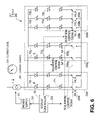
- FIG. 6 is a simplified electrical block diagram of another LED circuit used to drive the LED arrays shown in FIG. 4 , in accordance with an embodiment of the invention.
- FIG. 7 is a partly schematic side elevation or plan view of an embodiment employing multiple LED arrays of different emission wavelengths optically connected to separate light pipe integrators through multiple-respective fiber bundles;
- FIG. 8 is a simplified electrical block diagram of one embodiment of an LED circuit used to drive the LED arrays shown in FIG. 7 .
- FIG. 2 shows a single path embodiment of a multimedia projector 30 of the present invention that employs multiple, relatively monochromatic light sources 32 of two or more different wavelengths.
- Light sources 32 are light emitting devices (LEDs) or LED arrays and are driven by an LED circuit 200 powered by a power supply 34 .
- the LEDs are preferably light emitting diodes or laser diodes, but can be any device capable of emitting light when driven by an LED circuit 200 .
- Light emitted from light source 32 generally propagates along separate and common portions of an optical path 36 that may include light transmission guides 38 , an optical integrator 40 , one or more optical path lenses 42 , a display device 44 , a projection lens group 46 and various other optical components known to skilled persons.
- Display device 44 is preferably a digital micro-mirror device (DMD) but may alternatively be a reflective liquid crystal on semiconductor (LCOS) array device or an LCD light valve.
- Projection lens group 46 preferably includes a fixed focal length lens but may also include a varifocal or zoom lens.
- the optical components are preferably held together by a magnesium die-cast optical frame 48 (only a portion of which is shown) within a projector housing (not shown) which is mechanically rigid and dissipates heat.
- Such frames and housings are well known to skilled persons and can be adapted to house a cooling fan 50 for cooling the optical components and facilitate cooling air flow.
- Power supply 34 can also be used to power a cooling fan (not shown in FIG. 2 ) and display controller 56 .
- Display controller 56 includes a microprocessor which is capable of receiving color image data from a multimedia device 58 , such as a personal computer or a video device, and processes the image data into frame sequential red, green, and blue image data, sequential frames of which are conveyed to display device 44 in proper synchronism with control signals sent to LED circuit 200 or power supply 34 to activate and control the light sources 32 that emit the corresponding color.
- a multimedia device 58 such as a personal computer or a video device
- display controller 56 controls a high-density array of digitally deflected mirrors in display device 44 such that light propagating from lens 42 is selectively reflected by each mirror in the array either toward projection lens 46 or toward a light-absorbing surface 60 mounted on or near optical frame 48 .
- the light reflecting off mirrors of display device 44 oriented in the ON direction propagates through projection lens 46 for display on a screen (not shown), and the light reflecting off mirrors of display device 44 oriented in the OFF direction is absorbed by light-absorbing surface 60 .
- DMD 44 is preferably a Texas Instruments Model DMD 1076 spatial light modulator composed of a rectangular array of aluminum micro mechanical mirrors, each of which can be individually deflected at an angle of, for example, ⁇ 10 degrees or more about a hinged diagonal axis.
- the deflection angle (either positive or negative) of the mirrors is individually, controlled by changing the memory contents of underlying addressing circuitry and mirror reset signals.
- display device 44 is, for example, a transmissive LCD
- the optical path 36 could propagate through it and straight through projection lens 46 without any bends.
- display device 44 is a transmissive LCD
- the light from light transmission guides 38 is first polarized by a polarizer that may form part of LCD 44 to create light having a selected pass orientation.
- the polarized light is then modulated by an informational pattern of pixels in LCD 44 .
- the fully inactive pixels rotate the polarized light by 90°, and the fully active pixels pass the polarized light without rotation.
- the modulated light then passes through a front polarizer (or analyzer) that blocks the rotated light of the fully activated pixels and passes the nonrotated light of the fully inactive pixels.
- the modulated light particularly the light passing through the inactive pixels, is directed through projection lens 46 for viewing.
- LCDs 44 would be reflective LCDs and for FIG. 9 LCDs 44 would be transmissive LCDs such as XGA-resolution LCDs manufactured by Sony Electronic, Inc., under model number LCX017AL.
- FIG. 3 presents an embodiment in which light sources 32 comprise multiple LED arrays 70 of multiple LEDs 72 on a substrate 74 and light transmission guides 38 include optical fibers 76 .
- Light sources 32 may also comprise arrays of multiple laser diodes as the multiple LED arrays 70 without departing from the principles of the invention. Ends of optical fibers 76 extend through, and are held in place by, holes in a cover plate 80 and are mated to LEDs 72 in a one-to-one relationship. In this embodiment, the LEDs 72 and holes are aligned in rows 82 and columns 84 .
- light sources 32 include multiple LED arrays 70 which, when supplied with about 200 Watts, each emit light in one of the three additive primary wavelengths: red, green, and blue, at an efficiency of about 30%–50%.
- the blue LEDs 72 b can be HPWL series, manufactured by Hewlett Packard (HP), that emit 4.1 lumens per Watt in a wavelength range of 455–485 nm.
- the green LEDs 72 g can be HPWL series, also manufactured by HP, that emit 11.6 lumens per Watt in a wavelength range of 515–545 nm;
- the red LEDs 72 r can be HPWL series, also manufactured by HP, that emit 11 lumens per Watt in a wavelength range of 610–650 ⁇ m.
- LEDs 72 can be spaced apart as desired to facilitate dissipation of heat. Skilled persons will also appreciate that LED array 70 may comprise a side emitting bar of laser diodes.
- LED array 70 is attached to 18 optical fibers 76 that are collected into one or more optical bundles 86 that may have a cumulative output area of less than 56 mm 2 .
- LED array 70 has a greater area of substrate surface 114 that the output area of its respective optical fiber bundle 86 so the light exiting the bundle output area has greater intensity (and less heat) than the light emitted from surface 114 of the LED array 70 .
- a single LED array 70 can contain LEDs that all emit the same wavelength or can have rows 82 , columns 84 , or groupings of different wavelength LEDs 72 b , 72 g , and/or 72 r as demonstrated in FIG. 3 .
- emission intensity, heat dissipation characteristics, and manufacturing cost may also play a role in determining the spacing and size of LEDs 72 and/or the size and number of LED arrays 70 that are employed.
- FIG. 4 shows one embodiment of a single path projector 30 employing single color LED arrays 70 r , 70 g , and 70 b having respective red, green, and blue emission wavelengths.
- Optical fibers 76 from each similarly colored LED 72 , LED array 70 , or group of LED arrays 70 can be bundled into a common fiber bundle 86 , which can be subsequently coupled into an optical integrator 40 .
- display controller 56 generates control signals to LED circuit 200 / 220 and power supply 34 (as explained in more detail in FIGS.
- An LED-lighted single path projector 30 provides a light-weight, simple, bright, and inexpensive multimedia projection system.
- a variety of LED color options can be employed.
- white light from additional LED arrays or other white sources such as HID or arc lamps can be employed in a separate color time frame or selectively added to frames employing other colors.
- LED arrays 70 r , 70 g , and 70 b can be employed simultaneously to create a white color time frame.
- the output ends of approximately 200 or more fiber bundles 86 are coupled to the input end of optical integrator 40 . If photometrically weighted intensity (white balanced at optimum luminance) of the blue, green, and red LED arrays 70 described above are desired, then approximately 45 blue LEDs 72 , 105 green LEDs 72 , and 50 red LEDs 72 would be employed to produce 2000 lumens of white light. Skilled persons will appreciate that white balancing can be accomplished or fine tuned by modulating the amount of time for which each different color LED array 70 is activated.
- FIG. 5 illustrates one embodiment of an LED circuit 200 used to drive LED arrays 70 r , 70 g , and 70 b in the single path embodiment shown in FIG. 4 .
- LED circuit 200 contains LEDs 72 where each similarly colored LEDs 72 r , 72 g , and 72 b are arranged in series to form color channels 204 r , 204 g , and 204 b for each color.
- Display controller 56 generates control signals 202 in a sequence that corresponds to the sequence of the frame sequential color image data from personal computer 58 to control power supply 34 , which powers the current source 206 to LED circuit 200 .
- the control signals 202 operate to cause the power supply 34 to turn the power to current source 2060 N or OFF.
- the control signals can also operate to cause the power supply 34 to adjust the power to current source 206 to change the current level 210 . Higher current levels 210 cause the LEDs to emit brighter light and lower current levels cause the LEDs to emit dimmer light.
- display controller 56 generates control signals 202 , also in a sequence that corresponds to the sequence of the frame sequential color image data from personal computer 58 , to control switches SW_R 208 r , SW_G 208 g , and SW_B 208 b .
- switches SW_R 208 r When the switches 208 are in the OPEN position the current path 212 is interrupted, and corresponding color channels 204 and LEDs 72 are turned OFF (i.e. do not emit light), and when switches 208 are in the CLOSED position the current path 212 is resumed, and corresponding color channels 204 and LEDs 72 are turned ON (i.e. emit light).
- LED circuit 200 allows full brightness of the light source 32 because it is unnecessary to blank the sequential image on the display device 44 to change the color or the color's brightness. As a result, the display controller 56 can maintain a constant current source 206 and constant light emission to provide the display device 44 with a full-time duty cycle. Moreover, instead of relying on fixed voltages and resistors to drop the voltage for the different color LEDs, which is an inefficient use of power, LED circuit 200 provides for lower power consumption by allowing for the fact that the different color LEDs 72 have different voltage drops. Specifically, the display controller 56 generates control signals 202 to power supply 34 and switches 208 to adjust the current level 210 in coordination with the current path 212 through the color channels 204 to accommodate the different voltage requirements of the different color LEDs 72 .
- FIG. 6 illustrates an alternative embodiment of an LED circuit 220 used to drive LED arrays 70 r , 70 g , and 70 b in the single path embodiment shown in FIG. 4 .
- LED circuit 220 in FIG. 6 contains LEDs 72 where each similarly colored LEDs 72 r , 72 g , and 72 b are arranged in various combinations of series parallel arrays to form color channels 204 r , 204 g , and 204 b for each color.
- Display controller generates control signals 202 to the power supply 34 and to the switches 208 in a manner similar to LED circuit 200 in FIG. 5 .
- the display controller 56 can then match the light output of each color channel with a constant current source 206 to adjust the final mixed white-point color emitted by light source 32 .
- the display controller 56 matches the light output of each color channel by generating control signals 202 to switches 208 to alter the current path 212 , thereby altering the number of LEDs 72 activated or de-activated (i.e. turned ON or OFF) for a given color.
- the combination of series-parallel arrays of each color LED provides redundancy so that when one or more LEDs 72 or channels 204 of a given color fail, other LEDs or channels are still available.
- the display controller 56 adjusts the duty cycle of each of the color channels 204 to re-balance the color emitted by the light source 32 by generating appropriate control signals 202 to power supply 34 and switches 208 .
- FIG. 7 shows an embodiment of a triple path projector 120 employing single color LED arrays 70 r , 70 g , and 70 b that emit light that propagates along separated respective optical paths 36 r , 36 g , and 36 b , including propagating through respective fiber bundles 86 r , 86 g , and 86 b to respective separate light pipe integrators 40 and through respective display devices 44 r , 44 g , and 44 b , which are preferably LCDs.
- Optical paths 36 r , 36 g , and 36 b meet at an optical combiner 122 , which emits a composite image to lenses 42 and 46 .
- Display controller 56 generates control signals to LED circuit 240 and power 34 to synchronize the continuous light output of groups of similarly colored LEDs 72 with the color image data from personal computer 58 (as explained in more detail in FIG. 8 ).
- LED circuit 240 and power 34 to synchronize the continuous light output of groups of similarly colored LEDs 72 with the color image data from personal computer 58 (as explained in more detail in FIG. 8 ).
- a variety of LED color options can be employed.
- white light from additional LED arrays or other white sources such as HID or arc lamps can be input, for example, into a fourth side of combiner 122 to enhance brightness and could be employed with or without a display device 44 .
- FIG. 8 illustrates an alternative embodiment of an LED circuit 240 used to drive LED arrays 70 r , 70 g , and 70 b in the triple path embodiment shown in FIG. 7 .
- LED circuit 240 in FIG. 8 contains LEDs 72 where, for example, similarly colored LEDs 72 r and 72 g are arranged in series to form color channels 204 r and 204 g , and similarly colored LEDs 72 b are arranged in a series parallel array to form color channel 204 b .
- Various combinations of series and series parallel arrays of LEDs 72 other than those illustrated in FIG. 8 may be used to form color channels 204 without departing from the principles or exceeding the scope of the invention.
- LED arrays 70 r , 70 g , and 70 b can be left on continuously and do not require color frame synchronization. Instead, using control signals 202 to control the power supply 34 and current level 210 of each separate current source 206 in LED circuit 240 , display controller 56 synchronizes the continuous light output provided to display devices 44 r , 44 g , and 44 b .
- the display devices 44 r , 44 g , and 44 b are properly oriented with respect to each other and combiner 122 to generate the composite image. Such an image could be about 50% brighter than in a single path embodiment where each color is projected only 1 ⁇ 3 of the time for each image frame.
- each LED array 70 is driven from a separate current source 206 and current level 210 as controlled by display controller 56 through power supply 34 .
- Display controller 56 generates control signals 202 to the power supply 34 in a manner similar to LED circuits 200 and 220 in FIGS. 5–6 .
- LED circuit 240 is provided with a display controller 56 that can simultaneously adjust the current level 210 of each individual LED array's separate current source 206 to achieve the desired continuous color output from each color channel 204 .
- the control signals 202 to the power supply 34 operate to adjust the brightness or intensity of the continuous color output and not just to turn the colors ON or OFF.
- LED circuit 240 may also be provided with various combinations of redundant LEDs 72 and LED arrays 70 to improve reliability.
- the current sources used in the embodiments of LED circuits 200 , 220 , and 240 can be either simple pass elements such as a field-effect transistor (FET) operated in a linear mode, or a switching regulator design such as is found in an HID ballast with current control. These types of current sources are well-known to those skilled in the art and thus will not be discussed further except as they pertain to the present invention.
- FET field-effect transistor
- this invention is suitable for use with many differently folding optical paths, separate wavelength light sources, and alternative display devices, display controllers, and FSC data formats. Accordingly, it will be appreciated that this invention is also applicable to color synchronization applications other than those found in multimedia projectors.
- the scope of the present invention should, therefore, be determined only by the following claims.
Landscapes
- Engineering & Computer Science (AREA)
- Multimedia (AREA)
- Signal Processing (AREA)
- Physics & Mathematics (AREA)
- Computer Hardware Design (AREA)
- General Physics & Mathematics (AREA)
- Theoretical Computer Science (AREA)
- Control Of Indicators Other Than Cathode Ray Tubes (AREA)
- Projection Apparatus (AREA)
- Semiconductor Lasers (AREA)
- Liquid Crystal (AREA)
- Liquid Crystal Display Device Control (AREA)
Abstract
Description
Claims (37)
Priority Applications (4)
| Application Number | Priority Date | Filing Date | Title |
|---|---|---|---|
| US09/823,448 US7088321B1 (en) | 2001-03-30 | 2001-03-30 | Method and apparatus for driving LED light sources for a projection display |
| PCT/US2002/008064 WO2002080136A1 (en) | 2001-03-30 | 2002-03-14 | Method and apparatus for driving led light sources for a projection display |
| JP2002578278A JP4173007B2 (en) | 2001-03-30 | 2002-03-14 | Method and apparatus for driving an LED light source for a projection display device |
| EP02715132A EP1397792A4 (en) | 2001-03-30 | 2002-03-14 | METHOD AND DEVICE FOR CONTROLLING LED LIGHT SOURCES FOR A PROJECTION DISPLAY |
Applications Claiming Priority (1)
| Application Number | Priority Date | Filing Date | Title |
|---|---|---|---|
| US09/823,448 US7088321B1 (en) | 2001-03-30 | 2001-03-30 | Method and apparatus for driving LED light sources for a projection display |
Publications (1)
| Publication Number | Publication Date |
|---|---|
| US7088321B1 true US7088321B1 (en) | 2006-08-08 |
Family
ID=25238794
Family Applications (1)
| Application Number | Title | Priority Date | Filing Date |
|---|---|---|---|
| US09/823,448 Expired - Lifetime US7088321B1 (en) | 2001-03-30 | 2001-03-30 | Method and apparatus for driving LED light sources for a projection display |
Country Status (4)
| Country | Link |
|---|---|
| US (1) | US7088321B1 (en) |
| EP (1) | EP1397792A4 (en) |
| JP (1) | JP4173007B2 (en) |
| WO (1) | WO2002080136A1 (en) |
Cited By (49)
| Publication number | Priority date | Publication date | Assignee | Title |
|---|---|---|---|---|
| US20050140937A1 (en) * | 2003-12-26 | 2005-06-30 | Olympus Corporation | Image projector |
| US20050149149A1 (en) * | 2002-10-07 | 2005-07-07 | Chung Dong-Chune C. | Phototherapy system and device |
| US20050174546A1 (en) * | 2004-02-10 | 2005-08-11 | Fujinon Corporation | Rear projection apparatus |
| US20050206325A1 (en) * | 2004-03-19 | 2005-09-22 | Tohoku Pioneer Corporation | Drive device and drive method of light emitting elements |
| US20050219475A1 (en) * | 2004-03-31 | 2005-10-06 | Kabushiki Kaisha Toshiba | Illumination device integrated into a projection type display, and projection type projector |
| US20050243223A1 (en) * | 2004-04-30 | 2005-11-03 | Slobodin David E | Light emitting device driving method and projection apparatus so equipped |
| US20060062013A1 (en) * | 2004-09-22 | 2006-03-23 | Olympus Corporation | Light guiding apparatus, illumination apparatus and image projection system |
| US20060072078A1 (en) * | 2004-10-01 | 2006-04-06 | Kim Su-Gun | Illumination unit having an LED and image projecting apparatus employing the same |
| US20060146297A1 (en) * | 2005-01-05 | 2006-07-06 | Lee Kye-Hoon | LED package, display panel, illumination system and projection system employing the same |
| US20060192924A1 (en) * | 2003-04-23 | 2006-08-31 | Seiko Epson Corporation | Projector and optical device |
| US20060221305A1 (en) * | 2005-03-30 | 2006-10-05 | 3M Innovative Properties Company | Illumination system and projection system using same |
| US20060262282A1 (en) * | 2005-05-20 | 2006-11-23 | 3M Innovative Properties Company | Multicolor illuminator system |
| US20070001943A1 (en) * | 2005-07-01 | 2007-01-04 | Samsung Electronics Co., Ltd. | Display apparatus and control method thereof |
| US20070019166A1 (en) * | 2004-03-31 | 2007-01-25 | Brother Kogyo Kabushiki Kaisha | Projection Apparatus and Three-Dimensional-Shape Detection Apparatus |
| US20070030401A1 (en) * | 2005-08-03 | 2007-02-08 | Wen-Chang Chien | Projection apparatus, illumination module and color-level correcting method therefor |
| US20070126994A1 (en) * | 2005-12-05 | 2007-06-07 | Samsung Electronics Co., Ltd. | Optical device and projection system comprising the same |
| US20070195276A1 (en) * | 2003-07-16 | 2007-08-23 | Plut William J | Projection-type display devices with reduced speckle |
| US7282887B1 (en) * | 2006-02-16 | 2007-10-16 | Williams Kevin R | Laser diode triggered soft start controller for a polyphase electric motor |
| US20070268700A1 (en) * | 2004-11-19 | 2007-11-22 | Whiterock Design, Llc | Optical system with array light source |
| US20080007885A1 (en) * | 2006-07-05 | 2008-01-10 | Texas Instruments Incorporated | System for improving LED illumination reliability in projection display systems |
| US20080043150A1 (en) * | 2005-09-01 | 2008-02-21 | Texas Instruments Incorporated | Managing the Color Temperature for a Light Source Array |
| US20080252863A1 (en) * | 2007-04-16 | 2008-10-16 | Mitsubishi Electric Corporation | Projection display apparatus |
| US20090009730A1 (en) * | 2007-07-02 | 2009-01-08 | Texas Instruments Incorporated | Light Recycling in a Micromirror-Based Projection Display System |
| US20090033603A1 (en) * | 2007-08-01 | 2009-02-05 | Himax Technologies Limited | Projection type display apparatus |
| US20090066718A1 (en) * | 2007-09-07 | 2009-03-12 | Andrew Ian Russell | System and Method for Image-based Color Sequence Reallocation |
| US20090066620A1 (en) * | 2007-09-07 | 2009-03-12 | Andrew Ian Russell | Adaptive Pulse-Width Modulated Sequences for Sequential Color Display Systems |
| US20090091467A1 (en) * | 2007-10-09 | 2009-04-09 | Ries Ii Jack Leighton | Extended life led fixture |
| US20090231358A1 (en) * | 2008-02-14 | 2009-09-17 | Photonica, Inc. | Hybrid Telecom Network-structured Architecture and System for Digital Image Distribution, Display and Projection |
| US20090244499A1 (en) * | 2008-03-31 | 2009-10-01 | Terry Alan Bartlett | System and Method for a Projection Display System Using an Optical Lightguide |
| US20090303443A1 (en) * | 2006-07-27 | 2009-12-10 | Dilitronics Gmbh | Image Projection Device |
| CN101339351B (en) * | 2007-07-05 | 2010-05-26 | 上海飞锐光电科技有限公司 | Compact structure three piece type LCOS projector optical engine |
| CN101359097B (en) * | 2007-07-31 | 2010-05-26 | 上海飞锐光电科技有限公司 | Optical engines of hand-held three-sheet type LCOS projector |
| CN101846869A (en) * | 2009-03-27 | 2010-09-29 | 三洋电机株式会社 | Projection display apparatus |
| US20110157557A1 (en) * | 2008-08-06 | 2011-06-30 | Airbus Operations Gmbh | Area projection system for reproducing a visual signal on a surface |
| WO2011084837A1 (en) * | 2010-01-05 | 2011-07-14 | 3M Innovative Properties Company | Controlling light sources for colour sequential image displaying |
| US20110204327A1 (en) * | 2008-10-17 | 2011-08-25 | National University Corporation Hokkaido University | Semiconductor light-emitting element array and manufacturing method thereof |
| US20110274131A1 (en) * | 2009-01-20 | 2011-11-10 | Furukawa Electric Co., Ltd. | Two-dimensional surface-emitting laser array element, surface-emitting laser device and light source |
| US20120043911A1 (en) * | 2010-08-20 | 2012-02-23 | Semiconductor Energy Laboratory Co., Ltd. | Lighting Device |
| US8199100B1 (en) * | 2006-05-31 | 2012-06-12 | The Board Of Trustees Of The Leland Stanford Junior University | Display arrangement and approaches therefor |
| US20120236373A1 (en) * | 2011-03-18 | 2012-09-20 | Ricoh Company, Limited | Light-source control device, light-source control method, image reading device, and image forming apparatus |
| US20130038838A1 (en) * | 2011-06-03 | 2013-02-14 | Texas Instruments Incorporated | Optically efficient polarized projector |
| US20150310800A1 (en) * | 2012-11-29 | 2015-10-29 | Leyard Optoelectronic Co., Ltd | LED Display |
| US9355589B2 (en) * | 2012-11-29 | 2016-05-31 | Leyard Optoelectronic Co., Ltd. | LED display |
| US20170043594A1 (en) * | 2015-01-26 | 2017-02-16 | Fuji Xerox Co., Ltd. | Light emitting elements drive control device, droplets-deposited layer drying device and image processing apparatus |
| US9605823B2 (en) * | 2015-06-18 | 2017-03-28 | Bruce Alexander BARHAM | Lighting apparatus |
| US9651854B2 (en) | 2014-08-21 | 2017-05-16 | Coretronic Corporation | Projector |
| CN109254487A (en) * | 2018-09-17 | 2019-01-22 | 苏州佳世达光电有限公司 | Projection arrangement |
| US20190369254A1 (en) * | 2018-05-29 | 2019-12-05 | Huawei Technologies Co., Ltd. | Liquid crystal on silicon (lcos) lidar scanner with multiple light sources |
| US11258995B2 (en) * | 2019-01-23 | 2022-02-22 | Qisda Corporation | Light emitting diode projector and drive circuit thereof |
Families Citing this family (17)
| Publication number | Priority date | Publication date | Assignee | Title |
|---|---|---|---|---|
| US7714824B2 (en) | 2001-06-11 | 2010-05-11 | Genoa Color Technologies Ltd. | Multi-primary display with spectrally adapted back-illumination |
| WO2004107025A2 (en) * | 2003-05-27 | 2004-12-09 | Genoa Color Technologies Ltd. | Multi-primary display with spectrally adapted back-illumination |
| US7019736B2 (en) | 2002-03-20 | 2006-03-28 | Hewlett-Packard Development Company, L.P. | Method and apparatus for image display |
| KR100659531B1 (en) | 2003-11-27 | 2006-12-19 | 삼성에스디아이 주식회사 | Backlight driving circuit |
| JP2005257790A (en) * | 2004-03-09 | 2005-09-22 | Olympus Corp | Illumination apparatus and image projection apparatus using the same |
| JP2005259426A (en) * | 2004-03-10 | 2005-09-22 | Inter Action Corp | Light irradiation apparatus and image sensor testing apparatus |
| EP1581010A1 (en) * | 2004-03-26 | 2005-09-28 | Sony Deutschland GmbH | Image generation unit |
| KR100637437B1 (en) * | 2004-06-03 | 2006-10-20 | 삼성에스디아이 주식회사 | Liquid crystal display device |
| JP2006261160A (en) * | 2005-03-15 | 2006-09-28 | Mitsumi Electric Co Ltd | Inductive type LED driver |
| US7481541B2 (en) | 2005-04-22 | 2009-01-27 | Barco N.V. | Method and systems for projecting images |
| US7384150B2 (en) | 2005-05-27 | 2008-06-10 | 3M Innovative Properties Company | Light emitting diode (LED) illumination control system and method |
| FR2906396A1 (en) * | 2006-09-26 | 2008-03-28 | Thomson Licensing Sas | ELECTROLUMINESCENT DIODE ELEMENT ASSEMBLY FOR BACKLIGHT DEVICE, BACKLIGHT DEVICE, AND BACKLIGHT SCREEN. |
| US7547114B2 (en) | 2007-07-30 | 2009-06-16 | Ylx Corp. | Multicolor illumination device using moving plate with wavelength conversion materials |
| JP6000097B2 (en) * | 2012-12-06 | 2016-09-28 | 三菱電機株式会社 | Laser light source projector |
| TWI587277B (en) * | 2016-04-19 | 2017-06-11 | 邱智彥 | A display mould applicable to various displays |
| KR102496553B1 (en) * | 2017-12-29 | 2023-02-08 | 삼성디스플레이 주식회사 | Display device and driving method thereof |
| CN110677945A (en) * | 2019-09-24 | 2020-01-10 | 深圳市千百辉照明工程有限公司 | Synchronous terminal, LED light synchronous control method and system |
Citations (32)
| Publication number | Priority date | Publication date | Assignee | Title |
|---|---|---|---|---|
| US3740570A (en) * | 1971-09-27 | 1973-06-19 | Litton Systems Inc | Driving circuits for light emitting diodes |
| US3962702A (en) | 1974-03-01 | 1976-06-08 | Jenaer Glaswerk Schott & Gen. | Optical fiber display device |
| US4298869A (en) * | 1978-06-29 | 1981-11-03 | Zaidan Hojin Handotai Kenkyu Shinkokai | Light-emitting diode display |
| US4680579A (en) | 1983-09-08 | 1987-07-14 | Texas Instruments Incorporated | Optical system for projection display using spatial light modulator device |
| US4763975A (en) * | 1987-04-28 | 1988-08-16 | Spectra Diode Laboratories, Inc. | Optical system with bright light output |
| US4887074A (en) * | 1988-01-20 | 1989-12-12 | Michael Simon | Light-emitting diode display system |
| US4897639A (en) * | 1987-04-30 | 1990-01-30 | Fuji Photo Film Co., Ltd. | Image forming method and apparatus |
| US4943154A (en) | 1988-02-25 | 1990-07-24 | Matsushita Electric Industrial Co., Ltd. | Projection display apparatus |
| US5022043A (en) | 1989-12-20 | 1991-06-04 | Spectra-Physics | High power diode-pumped solid state laser with unstable resonator |
| US5108172A (en) * | 1989-08-11 | 1992-04-28 | Raf Electronics Corp. | Active matrix reflective image plane module and projection system |
| DE4234293A1 (en) * | 1992-10-12 | 1993-04-08 | Albert G Prof Dr Fischer | Flat matrix colour TV panel with quantum layer laser diodes - located in pattern circuit board using robot handling and emitting red, green and blue components |
| US5278542A (en) * | 1989-11-06 | 1994-01-11 | Texas Digital Systems, Inc. | Multicolor display system |
| US5293437A (en) * | 1992-06-03 | 1994-03-08 | Visual Optics, Inc. | Fiber optic display with direct driven optical fibers |
| US5430501A (en) | 1992-03-12 | 1995-07-04 | Mitsubishi Denki Kabushiki Kaisha | Compact video projector |
| US5526063A (en) * | 1992-07-24 | 1996-06-11 | Thomson-Csf | Video image projector with improve luminous efficiency |
| US5534949A (en) * | 1994-04-08 | 1996-07-09 | Hughes Aircraft Company | Two channel field sequential color display system |
| US5552840A (en) * | 1992-03-13 | 1996-09-03 | Sharp Kabushiki Kaisha | Three dimensional projection display reflecting divided polarized light on to reflective liquid crystal display elements |
| US5651599A (en) | 1991-02-22 | 1997-07-29 | Seiko Epson Corporation | Projection type liquid crystal projector |
| US5684368A (en) * | 1996-06-10 | 1997-11-04 | Motorola | Smart driver for an array of LEDs |
| US5724062A (en) * | 1992-08-05 | 1998-03-03 | Cree Research, Inc. | High resolution, high brightness light emitting diode display and method and producing the same |
| US5815221A (en) * | 1994-12-01 | 1998-09-29 | Mitsubishi Denki Kabushiki Kaisha | Projector apparatus |
| US5829858A (en) * | 1997-02-18 | 1998-11-03 | Levis; Maurice E. | Projector system with light pipe optics |
| US5920297A (en) | 1997-03-12 | 1999-07-06 | Hewlett-Packard Company | Front panel color annunciators for multi-channel instrument with color display |
| US5936599A (en) * | 1995-01-27 | 1999-08-10 | Reymond; Welles | AC powered light emitting diode array circuits for use in traffic signal displays |
| US5987190A (en) | 1992-10-01 | 1999-11-16 | Hudson Soft Co., Ltd. | Image processing system including a processor side memory and a display side memory |
| EP1006506A1 (en) | 1998-12-03 | 2000-06-07 | Hewlett-Packard Company | Optical vehicle display |
| US6097367A (en) * | 1996-09-06 | 2000-08-01 | Matsushita Electric Industrial Co., Ltd. | Display device |
| US6219014B1 (en) * | 1986-07-07 | 2001-04-17 | Texas Digital Systems, Inc. | Variable color display device having display area and background area |
| US6249088B1 (en) * | 1999-11-01 | 2001-06-19 | Philips Electronics North America Corporation | Three-dimensional lattice structure based led array for illumination |
| US6281949B1 (en) * | 1997-03-24 | 2001-08-28 | Sony Corporation | Apparatus for displaying a picture which involves spatially modulating a light beam |
| US6333724B1 (en) * | 1997-09-08 | 2001-12-25 | Kabushiki Kaisha Toshiba | Display device |
| US6480634B1 (en) * | 2000-05-18 | 2002-11-12 | Silicon Light Machines | Image projector including optical fiber which couples laser illumination to light modulator |
Family Cites Families (2)
| Publication number | Priority date | Publication date | Assignee | Title |
|---|---|---|---|---|
| US6184850B1 (en) * | 1991-09-04 | 2001-02-06 | Canon Kabushiki Kaisha | Image display apparatus with backlit display and method of driving the same |
| JP2000214825A (en) * | 1999-01-20 | 2000-08-04 | Nec Corp | Backlight display device and method |
-
2001
- 2001-03-30 US US09/823,448 patent/US7088321B1/en not_active Expired - Lifetime
-
2002
- 2002-03-14 EP EP02715132A patent/EP1397792A4/en not_active Withdrawn
- 2002-03-14 JP JP2002578278A patent/JP4173007B2/en not_active Expired - Lifetime
- 2002-03-14 WO PCT/US2002/008064 patent/WO2002080136A1/en not_active Ceased
Patent Citations (33)
| Publication number | Priority date | Publication date | Assignee | Title |
|---|---|---|---|---|
| US3740570A (en) * | 1971-09-27 | 1973-06-19 | Litton Systems Inc | Driving circuits for light emitting diodes |
| US3962702A (en) | 1974-03-01 | 1976-06-08 | Jenaer Glaswerk Schott & Gen. | Optical fiber display device |
| US4298869A (en) * | 1978-06-29 | 1981-11-03 | Zaidan Hojin Handotai Kenkyu Shinkokai | Light-emitting diode display |
| US4680579A (en) | 1983-09-08 | 1987-07-14 | Texas Instruments Incorporated | Optical system for projection display using spatial light modulator device |
| US6219014B1 (en) * | 1986-07-07 | 2001-04-17 | Texas Digital Systems, Inc. | Variable color display device having display area and background area |
| US4763975A (en) * | 1987-04-28 | 1988-08-16 | Spectra Diode Laboratories, Inc. | Optical system with bright light output |
| US4897639A (en) * | 1987-04-30 | 1990-01-30 | Fuji Photo Film Co., Ltd. | Image forming method and apparatus |
| US4887074A (en) * | 1988-01-20 | 1989-12-12 | Michael Simon | Light-emitting diode display system |
| US4943154A (en) | 1988-02-25 | 1990-07-24 | Matsushita Electric Industrial Co., Ltd. | Projection display apparatus |
| US5108172A (en) * | 1989-08-11 | 1992-04-28 | Raf Electronics Corp. | Active matrix reflective image plane module and projection system |
| US5278542A (en) * | 1989-11-06 | 1994-01-11 | Texas Digital Systems, Inc. | Multicolor display system |
| US5022043A (en) | 1989-12-20 | 1991-06-04 | Spectra-Physics | High power diode-pumped solid state laser with unstable resonator |
| US5651599A (en) | 1991-02-22 | 1997-07-29 | Seiko Epson Corporation | Projection type liquid crystal projector |
| US5430501A (en) | 1992-03-12 | 1995-07-04 | Mitsubishi Denki Kabushiki Kaisha | Compact video projector |
| US5552840A (en) * | 1992-03-13 | 1996-09-03 | Sharp Kabushiki Kaisha | Three dimensional projection display reflecting divided polarized light on to reflective liquid crystal display elements |
| US5293437A (en) * | 1992-06-03 | 1994-03-08 | Visual Optics, Inc. | Fiber optic display with direct driven optical fibers |
| US5526063A (en) * | 1992-07-24 | 1996-06-11 | Thomson-Csf | Video image projector with improve luminous efficiency |
| US5724062A (en) * | 1992-08-05 | 1998-03-03 | Cree Research, Inc. | High resolution, high brightness light emitting diode display and method and producing the same |
| US5987190A (en) | 1992-10-01 | 1999-11-16 | Hudson Soft Co., Ltd. | Image processing system including a processor side memory and a display side memory |
| DE4234293A1 (en) * | 1992-10-12 | 1993-04-08 | Albert G Prof Dr Fischer | Flat matrix colour TV panel with quantum layer laser diodes - located in pattern circuit board using robot handling and emitting red, green and blue components |
| US5534949A (en) * | 1994-04-08 | 1996-07-09 | Hughes Aircraft Company | Two channel field sequential color display system |
| US5815221A (en) * | 1994-12-01 | 1998-09-29 | Mitsubishi Denki Kabushiki Kaisha | Projector apparatus |
| US5936599A (en) * | 1995-01-27 | 1999-08-10 | Reymond; Welles | AC powered light emitting diode array circuits for use in traffic signal displays |
| US5684368A (en) * | 1996-06-10 | 1997-11-04 | Motorola | Smart driver for an array of LEDs |
| US6097367A (en) * | 1996-09-06 | 2000-08-01 | Matsushita Electric Industrial Co., Ltd. | Display device |
| US5829858A (en) * | 1997-02-18 | 1998-11-03 | Levis; Maurice E. | Projector system with light pipe optics |
| US5920297A (en) | 1997-03-12 | 1999-07-06 | Hewlett-Packard Company | Front panel color annunciators for multi-channel instrument with color display |
| US6281949B1 (en) * | 1997-03-24 | 2001-08-28 | Sony Corporation | Apparatus for displaying a picture which involves spatially modulating a light beam |
| US6333724B1 (en) * | 1997-09-08 | 2001-12-25 | Kabushiki Kaisha Toshiba | Display device |
| EP1006506A1 (en) | 1998-12-03 | 2000-06-07 | Hewlett-Packard Company | Optical vehicle display |
| US6396466B1 (en) * | 1998-12-03 | 2002-05-28 | Agilent Technologies | Optical vehicle display |
| US6249088B1 (en) * | 1999-11-01 | 2001-06-19 | Philips Electronics North America Corporation | Three-dimensional lattice structure based led array for illumination |
| US6480634B1 (en) * | 2000-05-18 | 2002-11-12 | Silicon Light Machines | Image projector including optical fiber which couples laser illumination to light modulator |
Cited By (102)
| Publication number | Priority date | Publication date | Assignee | Title |
|---|---|---|---|---|
| US20050149149A1 (en) * | 2002-10-07 | 2005-07-07 | Chung Dong-Chune C. | Phototherapy system and device |
| US7438719B2 (en) * | 2002-10-07 | 2008-10-21 | Natus Medical Incorporated | Phototherapy system and device |
| US20060192924A1 (en) * | 2003-04-23 | 2006-08-31 | Seiko Epson Corporation | Projector and optical device |
| US7553033B2 (en) * | 2003-04-23 | 2009-06-30 | Seiko Epson Corporation | Projector and optical device |
| US7510284B2 (en) * | 2003-07-16 | 2009-03-31 | Plut William J | Projection-type display devices including redundant laser sets |
| US20070195276A1 (en) * | 2003-07-16 | 2007-08-23 | Plut William J | Projection-type display devices with reduced speckle |
| US8147074B2 (en) | 2003-07-16 | 2012-04-03 | Transpacific Image, Llc | Positioning interfaces for projection display devices |
| US20100171936A1 (en) * | 2003-07-16 | 2010-07-08 | Plut William J | Positioning interfaces for projection display devices |
| US7806535B2 (en) | 2003-07-16 | 2010-10-05 | Plut William J | Low power projection display devices |
| US7703930B2 (en) | 2003-07-16 | 2010-04-27 | Plut William J | Positioning interfaces for projection display devices |
| US20070285344A1 (en) * | 2003-07-16 | 2007-12-13 | Plut William J | Low power projection display devices |
| US8366282B2 (en) | 2003-07-16 | 2013-02-05 | Transpacific Image, Llc | Positioning interfaces for projection display devices |
| US20070205300A1 (en) * | 2003-07-16 | 2007-09-06 | Plut William J | Positioning interfaces for projection display devices |
| US8641209B2 (en) | 2003-07-16 | 2014-02-04 | Transpacific Image, Llc | Positioning interfaces for projection display devices |
| US20080111974A1 (en) * | 2003-07-16 | 2008-05-15 | Plut William J | Projection-type display devices including redundant laser sets |
| US7237910B2 (en) * | 2003-12-26 | 2007-07-03 | Olympus Corporation | Image projector |
| US20050140937A1 (en) * | 2003-12-26 | 2005-06-30 | Olympus Corporation | Image projector |
| US7329010B2 (en) * | 2004-02-10 | 2008-02-12 | Fujinon Corporation | Rear projection apparatus |
| US20050174546A1 (en) * | 2004-02-10 | 2005-08-11 | Fujinon Corporation | Rear projection apparatus |
| US7274151B2 (en) * | 2004-03-19 | 2007-09-25 | Tohoku Pioneer Corporation | Drive device and drive method of light emitting elements |
| US20050206325A1 (en) * | 2004-03-19 | 2005-09-22 | Tohoku Pioneer Corporation | Drive device and drive method of light emitting elements |
| US20050219475A1 (en) * | 2004-03-31 | 2005-10-06 | Kabushiki Kaisha Toshiba | Illumination device integrated into a projection type display, and projection type projector |
| US20070019166A1 (en) * | 2004-03-31 | 2007-01-25 | Brother Kogyo Kabushiki Kaisha | Projection Apparatus and Three-Dimensional-Shape Detection Apparatus |
| US7845807B2 (en) * | 2004-03-31 | 2010-12-07 | Brother Kogyo Kabushiki Kaisha | Projection apparatus and three-dimensional-shape detection apparatus |
| US7408527B2 (en) * | 2004-04-30 | 2008-08-05 | Infocus Corporation | Light emitting device driving method and projection apparatus so equipped |
| US20050243223A1 (en) * | 2004-04-30 | 2005-11-03 | Slobodin David E | Light emitting device driving method and projection apparatus so equipped |
| US20060062013A1 (en) * | 2004-09-22 | 2006-03-23 | Olympus Corporation | Light guiding apparatus, illumination apparatus and image projection system |
| US7396136B2 (en) * | 2004-10-01 | 2008-07-08 | Samsung Electronics Co., Ltd. | Illumination unit having an LED and image projecting apparatus employing the same |
| US20060072078A1 (en) * | 2004-10-01 | 2006-04-06 | Kim Su-Gun | Illumination unit having an LED and image projecting apparatus employing the same |
| US7901089B2 (en) * | 2004-11-19 | 2011-03-08 | Whiterock Design, Llc | Optical system with array light source |
| US20070268700A1 (en) * | 2004-11-19 | 2007-11-22 | Whiterock Design, Llc | Optical system with array light source |
| US20060146297A1 (en) * | 2005-01-05 | 2006-07-06 | Lee Kye-Hoon | LED package, display panel, illumination system and projection system employing the same |
| US7789517B2 (en) * | 2005-01-05 | 2010-09-07 | Samsung Electronics Co., Ltd | LED package, display panel, illumination system and projection system employing the same |
| US7422330B2 (en) * | 2005-03-30 | 2008-09-09 | 3M Innovative Properties Company | Illumination system and projection system using same |
| US20060221305A1 (en) * | 2005-03-30 | 2006-10-05 | 3M Innovative Properties Company | Illumination system and projection system using same |
| US7410261B2 (en) | 2005-05-20 | 2008-08-12 | 3M Innovative Properties Company | Multicolor illuminator system |
| US20060262282A1 (en) * | 2005-05-20 | 2006-11-23 | 3M Innovative Properties Company | Multicolor illuminator system |
| US20070001943A1 (en) * | 2005-07-01 | 2007-01-04 | Samsung Electronics Co., Ltd. | Display apparatus and control method thereof |
| US8159419B2 (en) | 2005-07-01 | 2012-04-17 | Samsung Electronics Co., Ltd. | Display apparatus and control method thereof |
| US7956937B2 (en) * | 2005-08-03 | 2011-06-07 | Coretronic Corporation | Projection apparatus and color-level correcting method therefor |
| US20070030401A1 (en) * | 2005-08-03 | 2007-02-08 | Wen-Chang Chien | Projection apparatus, illumination module and color-level correcting method therefor |
| US20080043150A1 (en) * | 2005-09-01 | 2008-02-21 | Texas Instruments Incorporated | Managing the Color Temperature for a Light Source Array |
| US7934840B2 (en) * | 2005-12-05 | 2011-05-03 | Samsung Electronics Co., Ltd. | Optical device and projection system comprising the same |
| US20070126994A1 (en) * | 2005-12-05 | 2007-06-07 | Samsung Electronics Co., Ltd. | Optical device and projection system comprising the same |
| US7282887B1 (en) * | 2006-02-16 | 2007-10-16 | Williams Kevin R | Laser diode triggered soft start controller for a polyphase electric motor |
| US20070241700A1 (en) * | 2006-02-16 | 2007-10-18 | Williams Kevin R | Laser diode triggered soft start controller for a polyphase electric motor |
| US8199100B1 (en) * | 2006-05-31 | 2012-06-12 | The Board Of Trustees Of The Leland Stanford Junior University | Display arrangement and approaches therefor |
| US20080007885A1 (en) * | 2006-07-05 | 2008-01-10 | Texas Instruments Incorporated | System for improving LED illumination reliability in projection display systems |
| WO2008005915A3 (en) * | 2006-07-05 | 2008-06-26 | Texas Instruments Inc | System for improving illumination reliability in projection display systems |
| US8231230B2 (en) * | 2006-07-27 | 2012-07-31 | Dilitronics Gmbh | Image projection device |
| US20090303443A1 (en) * | 2006-07-27 | 2009-12-10 | Dilitronics Gmbh | Image Projection Device |
| US20080252863A1 (en) * | 2007-04-16 | 2008-10-16 | Mitsubishi Electric Corporation | Projection display apparatus |
| US7950808B2 (en) * | 2007-04-16 | 2011-05-31 | Mitsubishi Electric Corporation | Project display apparatus having diffusion element for reducing speckle |
| US20090009730A1 (en) * | 2007-07-02 | 2009-01-08 | Texas Instruments Incorporated | Light Recycling in a Micromirror-Based Projection Display System |
| US7959305B2 (en) * | 2007-07-02 | 2011-06-14 | Texas Instruments Incorporated | Light recycling in a micromirror-based projection display system |
| CN101339351B (en) * | 2007-07-05 | 2010-05-26 | 上海飞锐光电科技有限公司 | Compact structure three piece type LCOS projector optical engine |
| CN101359097B (en) * | 2007-07-31 | 2010-05-26 | 上海飞锐光电科技有限公司 | Optical engines of hand-held three-sheet type LCOS projector |
| US20090033603A1 (en) * | 2007-08-01 | 2009-02-05 | Himax Technologies Limited | Projection type display apparatus |
| TWI384313B (en) * | 2007-08-01 | 2013-02-01 | 奇景光電股份有限公司 | Display device |
| US8542167B2 (en) * | 2007-08-01 | 2013-09-24 | Himax Technologies Limited | Projection type display apparatus |
| US8253755B2 (en) | 2007-09-07 | 2012-08-28 | Texas Instruments Incorporated | System and method for image-based color sequence reallocation |
| US8305387B2 (en) | 2007-09-07 | 2012-11-06 | Texas Instruments Incorporated | Adaptive pulse-width modulated sequences for sequential color display systems |
| US20090066718A1 (en) * | 2007-09-07 | 2009-03-12 | Andrew Ian Russell | System and Method for Image-based Color Sequence Reallocation |
| US20090066620A1 (en) * | 2007-09-07 | 2009-03-12 | Andrew Ian Russell | Adaptive Pulse-Width Modulated Sequences for Sequential Color Display Systems |
| US20090128054A1 (en) * | 2007-10-09 | 2009-05-21 | Ries Ii Jack Leighton | Extended Life LED Fixture with Central Controller and LED Lamps |
| US20090128052A1 (en) * | 2007-10-09 | 2009-05-21 | Ries Ii Jack Leighton | Extended Life LED Fixture with Distributed Controller and Multi-Chip LEDS |
| US8242927B2 (en) | 2007-10-09 | 2012-08-14 | Abl Ip Holding Llc | Extended life LED fixture with central controller and LED lamps |
| US8237582B2 (en) | 2007-10-09 | 2012-08-07 | Abl Ip Holding Llc | Extended life LED fixture with distributed controller and multi-chip LEDs |
| US7839295B2 (en) | 2007-10-09 | 2010-11-23 | Abl Ip Holding Llc | Extended life LED fixture |
| US20090091467A1 (en) * | 2007-10-09 | 2009-04-09 | Ries Ii Jack Leighton | Extended life led fixture |
| US8237581B2 (en) | 2007-10-09 | 2012-08-07 | Abl Ip Holding Llc | Extended life LED fixture with central controller and multi-chip LEDs |
| US20090231358A1 (en) * | 2008-02-14 | 2009-09-17 | Photonica, Inc. | Hybrid Telecom Network-structured Architecture and System for Digital Image Distribution, Display and Projection |
| US9584778B2 (en) * | 2008-02-14 | 2017-02-28 | Sutherland C. Ellwood, Jr. | Hybrid telecom network-structured architecture and system for digital image distribution, display and projection |
| US8157388B2 (en) * | 2008-03-31 | 2012-04-17 | Texas Instruments Incorporated | System and method for a projection display system using an optical lightguide |
| US20090244499A1 (en) * | 2008-03-31 | 2009-10-01 | Terry Alan Bartlett | System and Method for a Projection Display System Using an Optical Lightguide |
| US8616704B2 (en) * | 2008-08-06 | 2013-12-31 | Airbus Operations Gmbh | Area projection system for reproducing a visual signal on a surface |
| US20110157557A1 (en) * | 2008-08-06 | 2011-06-30 | Airbus Operations Gmbh | Area projection system for reproducing a visual signal on a surface |
| US8519378B2 (en) | 2008-10-17 | 2013-08-27 | National University Corporation Hokkaido University | Semiconductor light-emitting element array including a semiconductor rod |
| US20110204327A1 (en) * | 2008-10-17 | 2011-08-25 | National University Corporation Hokkaido University | Semiconductor light-emitting element array and manufacturing method thereof |
| US20110274131A1 (en) * | 2009-01-20 | 2011-11-10 | Furukawa Electric Co., Ltd. | Two-dimensional surface-emitting laser array element, surface-emitting laser device and light source |
| US20100245774A1 (en) * | 2009-03-27 | 2010-09-30 | Sanyo Electric Co., Ltd. | Projection display apparatus |
| CN101846869A (en) * | 2009-03-27 | 2010-09-29 | 三洋电机株式会社 | Projection display apparatus |
| CN102726049A (en) * | 2010-01-05 | 2012-10-10 | 3M创新有限公司 | Controlling light sources for colour sequential image displaying |
| WO2011084837A1 (en) * | 2010-01-05 | 2011-07-14 | 3M Innovative Properties Company | Controlling light sources for colour sequential image displaying |
| KR20120018083A (en) * | 2010-08-20 | 2012-02-29 | 가부시키가이샤 한도오따이 에네루기 켄큐쇼 | Lighting device |
| US20120043911A1 (en) * | 2010-08-20 | 2012-02-23 | Semiconductor Energy Laboratory Co., Ltd. | Lighting Device |
| US8866407B2 (en) * | 2010-08-20 | 2014-10-21 | Semiconductor Energy Laboratory Co., Ltd. | Lighting device |
| US20120236373A1 (en) * | 2011-03-18 | 2012-09-20 | Ricoh Company, Limited | Light-source control device, light-source control method, image reading device, and image forming apparatus |
| US8711444B2 (en) * | 2011-03-18 | 2014-04-29 | Ricoh Company, Limited | Light-source control device, light-source control method, image reading device, and image forming apparatus |
| US9261764B2 (en) * | 2011-06-03 | 2016-02-16 | Texas Instruments Incorporated | Optically efficient polarized projector |
| US20130038838A1 (en) * | 2011-06-03 | 2013-02-14 | Texas Instruments Incorporated | Optically efficient polarized projector |
| US20150310800A1 (en) * | 2012-11-29 | 2015-10-29 | Leyard Optoelectronic Co., Ltd | LED Display |
| US9355589B2 (en) * | 2012-11-29 | 2016-05-31 | Leyard Optoelectronic Co., Ltd. | LED display |
| US9651854B2 (en) | 2014-08-21 | 2017-05-16 | Coretronic Corporation | Projector |
| US20170043594A1 (en) * | 2015-01-26 | 2017-02-16 | Fuji Xerox Co., Ltd. | Light emitting elements drive control device, droplets-deposited layer drying device and image processing apparatus |
| US9840093B2 (en) * | 2015-01-26 | 2017-12-12 | Fuji Xerox Co., Ltd. | Light emitting elements drive control device, droplets-deposited layer drying device and image processing apparatus |
| US9605823B2 (en) * | 2015-06-18 | 2017-03-28 | Bruce Alexander BARHAM | Lighting apparatus |
| US20190369254A1 (en) * | 2018-05-29 | 2019-12-05 | Huawei Technologies Co., Ltd. | Liquid crystal on silicon (lcos) lidar scanner with multiple light sources |
| US10921453B2 (en) * | 2018-05-29 | 2021-02-16 | Huawei Technologies Co., Ltd. | Liquid crystal on silicon (LCOS) lidar scanner with multiple light sources |
| CN109254487A (en) * | 2018-09-17 | 2019-01-22 | 苏州佳世达光电有限公司 | Projection arrangement |
| US10935875B2 (en) * | 2018-09-17 | 2021-03-02 | Qisda Corporation | Projector with a dust resistance capability for long term operations |
| US11258995B2 (en) * | 2019-01-23 | 2022-02-22 | Qisda Corporation | Light emitting diode projector and drive circuit thereof |
Also Published As
| Publication number | Publication date |
|---|---|
| JP4173007B2 (en) | 2008-10-29 |
| EP1397792A1 (en) | 2004-03-17 |
| EP1397792A4 (en) | 2008-03-12 |
| JP2004533111A (en) | 2004-10-28 |
| WO2002080136A1 (en) | 2002-10-10 |
Similar Documents
| Publication | Publication Date | Title |
|---|---|---|
| US7088321B1 (en) | Method and apparatus for driving LED light sources for a projection display | |
| US6224216B1 (en) | System and method employing LED light sources for a projection display | |
| USRE44279E1 (en) | Lamp power pulse modulation in color sequential projection displays | |
| US6252636B1 (en) | Pulsed two lamp single light valve display system | |
| US7530708B2 (en) | Surface emitting light source and projection display device using the same | |
| US6419365B1 (en) | Asymmetrical tunnel for spatially integrating light | |
| US8976080B2 (en) | Multi-segment imager | |
| US6553168B2 (en) | Projection system utilizing fiber optic illumination | |
| JP4445432B2 (en) | 2-panel LCD on silicon color management system | |
| US20120212707A1 (en) | Multi-Segment Imager | |
| US7168810B2 (en) | Method and apparatus for arranging light emitting devices in projection systems | |
| JP2004037958A (en) | Single-panel image projection display | |
| US20060001838A1 (en) | Illuminating device and projection type video display | |
| JP4183663B2 (en) | Illumination device and projection display device | |
| WO2018133501A1 (en) | Projection display system | |
| USRE41768E1 (en) | System and method employing reflective imaging devices for a projection display | |
| US20060098170A1 (en) | Projection display device with enhanced light utilization efficiency | |
| US7567384B2 (en) | Method and apparatus for combining light paths of like-colored light sources | |
| US20050110955A1 (en) | Projection device | |
| JP4947626B2 (en) | Image projection device | |
| JP2007003847A (en) | Illuminator and projection type image display device | |
| US20080158516A1 (en) | High brightness display systems using multiple spatial light modulators | |
| WO2024254355A1 (en) | Selective illumination of a spatial light modulator | |
| JP2006215120A (en) | Illuminator and projection type video display device | |
| HK1062937B (en) | Lamp power pulse modulation in color sequential projection displays |
Legal Events
| Date | Code | Title | Description |
|---|---|---|---|
| AS | Assignment |
Owner name: INFOCUS CORPORATION, OREGON Free format text: ASSIGNMENT OF ASSIGNORS INTEREST;ASSIGNOR:PARKER, FREDERICK S.;REEL/FRAME:011930/0352 Effective date: 20010402 |
|
| STCF | Information on status: patent grant |
Free format text: PATENTED CASE |
|
| AS | Assignment |
Owner name: RPX CORPORATION, CALIFORNIA Free format text: ASSIGNMENT OF ASSIGNORS INTEREST;ASSIGNOR:INFOCUS CORPORATION;REEL/FRAME:023538/0709 Effective date: 20091019 Owner name: SEIKO EPSON CORPORATION, JAPAN Free format text: ASSIGNMENT OF ASSIGNORS INTEREST;ASSIGNOR:RPX CORPORATION;REEL/FRAME:023538/0889 Effective date: 20091026 Owner name: RPX CORPORATION,CALIFORNIA Free format text: ASSIGNMENT OF ASSIGNORS INTEREST;ASSIGNOR:INFOCUS CORPORATION;REEL/FRAME:023538/0709 Effective date: 20091019 Owner name: SEIKO EPSON CORPORATION,JAPAN Free format text: ASSIGNMENT OF ASSIGNORS INTEREST;ASSIGNOR:RPX CORPORATION;REEL/FRAME:023538/0889 Effective date: 20091026 |
|
| FEPP | Fee payment procedure |
Free format text: PAYOR NUMBER ASSIGNED (ORIGINAL EVENT CODE: ASPN); ENTITY STATUS OF PATENT OWNER: LARGE ENTITY |
|
| FPAY | Fee payment |
Year of fee payment: 4 |
|
| FPAY | Fee payment |
Year of fee payment: 8 |
|
| MAFP | Maintenance fee payment |
Free format text: PAYMENT OF MAINTENANCE FEE, 12TH YEAR, LARGE ENTITY (ORIGINAL EVENT CODE: M1553) Year of fee payment: 12 |