US7077245B2 - Torque controlled brake - Google Patents
Torque controlled brake Download PDFInfo
- Publication number
- US7077245B2 US7077245B2 US10/760,673 US76067304A US7077245B2 US 7077245 B2 US7077245 B2 US 7077245B2 US 76067304 A US76067304 A US 76067304A US 7077245 B2 US7077245 B2 US 7077245B2
- Authority
- US
- United States
- Prior art keywords
- brake
- disc
- cam part
- friction surface
- cam
- Prior art date
- Legal status (The legal status is an assumption and is not a legal conclusion. Google has not performed a legal analysis and makes no representation as to the accuracy of the status listed.)
- Expired - Lifetime
Links
- 230000008878 coupling Effects 0.000 claims description 15
- 238000010168 coupling process Methods 0.000 claims description 15
- 238000005859 coupling reaction Methods 0.000 claims description 15
- 230000008859 change Effects 0.000 claims description 4
- 230000009471 action Effects 0.000 claims description 2
- 230000008901 benefit Effects 0.000 description 4
- 238000005381 potential energy Methods 0.000 description 4
- 230000007246 mechanism Effects 0.000 description 2
- 230000001133 acceleration Effects 0.000 description 1
- 230000002730 additional effect Effects 0.000 description 1
- 230000000694 effects Effects 0.000 description 1
- 239000000314 lubricant Substances 0.000 description 1
- 230000007257 malfunction Effects 0.000 description 1
- 238000000034 method Methods 0.000 description 1
- 230000010355 oscillation Effects 0.000 description 1
- 230000001360 synchronised effect Effects 0.000 description 1
Images


Classifications
-
- B—PERFORMING OPERATIONS; TRANSPORTING
- B66—HOISTING; LIFTING; HAULING
- B66D—CAPSTANS; WINCHES; TACKLES, e.g. PULLEY BLOCKS; HOISTS
- B66D5/00—Braking or detent devices characterised by application to lifting or hoisting gear, e.g. for controlling the lowering of loads
- B66D5/02—Crane, lift hoist, or winch brakes operating on drums, barrels, or ropes
- B66D5/12—Crane, lift hoist, or winch brakes operating on drums, barrels, or ropes with axial effect
- B66D5/14—Crane, lift hoist, or winch brakes operating on drums, barrels, or ropes with axial effect embodying discs
-
- F—MECHANICAL ENGINEERING; LIGHTING; HEATING; WEAPONS; BLASTING
- F16—ENGINEERING ELEMENTS AND UNITS; GENERAL MEASURES FOR PRODUCING AND MAINTAINING EFFECTIVE FUNCTIONING OF MACHINES OR INSTALLATIONS; THERMAL INSULATION IN GENERAL
- F16D—COUPLINGS FOR TRANSMITTING ROTATION; CLUTCHES; BRAKES
- F16D59/00—Self-acting brakes, e.g. coming into operation at a predetermined speed
Definitions
- the invention relates to a torque controlled brake arranged between a drive shaft and a driven shaft, said brake comprising a brake disc/clutch disc arrangement arranged between the drive shaft and the driven shaft and comprising a first disc that is axially movingly but non-rotatably arranged on the driven shaft and a second disc that is axially movingly arranged between the first disc and the drive shaft, a first set of friction surface means arranged between the first disc and the second disc, a second set of friction surface means arranged between the second disc and a body of the brake, a spring arrangement arranged to axially press the discs and the friction surface means co-operating therewith against each other in order to achieve a braking engagement, and cam means arranged between the drive shaft and the brake disc/clutch disc arrangement, said means comprising a first cam part that is non-rotatably fastened to the drive shaft and a second cam part that is non-rotatably arranged on the second disc, the cam means causing by the impact of torque and rotation of the drive shaft and
- Such a brake is disclosed in Finnish patent application 20010714.
- a particular aim has been to better control the loads from the direction of the load in order to avoid safety risks.
- What has also been attempted to avoid is the acceleration of the motor over the synchronous speed caused by the oscillation of the load.
- Another object has been to expand the applications of the brake.
- a substantial feature of this prior art solution is the use of two brake wheels, whereby the torques achieved with such wheels have been differently adjusted. This has enabled to customize the brake for various purposes and to provide the brake with additional properties, which previously have required specific arrangements.
- the structure should allow combining different functions in a more diversified manner.
- a brake according to the invention characterized in that the second disc is axially movingly arranged in relation to the second cam part, and that a third set of friction surface means is arranged between the second cam part and the first disc in order to move the torque from the drive shaft to the driven shaft.
- the invention is based on a second brake disc/clutch disc, which moves more freely than previously, and whose course of motion can be adjusted such that the brake can always be opened against the brake torque by means of additional friction surfaces arranged for this purpose, thus ensuring the opening of the brake (the operation of the cam means) always when the brake should be opened.
- flywheel mass is also arranged at the second disc, for instance by means of a separate coupling wheel, on which the second disc and preferably also the third set of friction surface means are arranged, for instance a load torque affecting an input shaft of the hoisting gear forces the driven wheel, when the drive force driving the hoisting gear ends, for instance when the current of an electric motor is switched off, to accelerate at first the flywheel mass and then the actuator, such as a rotor of an electric motor.
- the actuator such as a rotor of an electric motor.
- the appropriate dimensions of the structure allow providing such a torque remaining after the flywheel mass that is unable to open the brake. In a hoisting apparatus this is a very important feature that enables to avoid the load from descending or from abruptly falling, for instance if malfunction or failure occurs in the actuator. In such an unexpected situation, as well as during the end of a normal hoisting procedure, braking is smooth on account of such a structure, and abrupt heavy dynamic loads directed at the braking system are avoided.
- the brake according to the invention can also easily be provided with a sliding clutch required in chain hoists, if desired.
- the body of the brake comprises two parts, which are axially adjustable in relation to one another, whereby the position or the point of action of the second set of friction surface means can be adjusted and limited by means of a second body part.
- the torque of the clutch and the brake is provided using the same spring force of the spring arrangement and the ratio between the two is handled by selecting the ratio of corresponding friction surfaces to be the same as the ratio between the clutch torque and the brake torque.
- This arrangement provides such an advantage that when the torque of a sliding clutch is being adjusted, the torque of the brake changes at the same time in correct relation to the clutch torque.
- the clutch torque can be adjusted while the actuator rotates, in the simplest form by rotating the second body part of the brake, thus also providing the clutch with a precisely correct adjustment, since only a dynamic friction coefficient is employed during adjustment.
- the spring arrangement preferably comprises a spring array pressing the first disc towards the second cam part, and a second spring array pressing the first cam part towards the second cam part, and that the spring force of the first spring array is considerably greater than the spring force of the second spring array.
- the second spring array centres the cam parts in relation to one another and the force thereof is selected such that it does not excessively reduce the actual spring force of the first spring array providing the brake torque.
- the play in the first spring array also compensates for the wear of the friction surfaces.
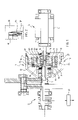
- FIG. 1 shows a longitudinal view in cross section of a brake according to the invention between a chain hoist and a hand-operated hoist, the brake being in a state in which the load is placed upon the brake;
- FIG. 2 shows an enlarged detail of a brake disc/clutch disc arrangement shown in FIG. 1 ;
- FIG. 3 illustrates the brake shown in FIG. 2 in a state in which the load is hoisted
- FIG. 4 illustrates an enlarged detail of a second spring array shown in FIG. 1 ;
- FIG. 5 illustrates an embodiment of the cam parts of the brake shown in the previous Figures.
- FIG. 6 shows a longitudinal view in cross section of the brake according to the invention in connection with the chain hoist and an electric motor using it, the brake being in a state in which the load is placed upon the brake.
- a torque controlled brake 1 according to the invention is shown that is arranged between a chain hoist 2 and a hand-operated hoist 3 .
- a rotor 4 of the hand-operated hoist 3 operates as a drive shaft of the system.
- the brake 1 comprises firstly cam parts 5 and 6 , the first one of which indicated with reference numeral 5 is non-rotatably fastened to the rotor 4 , while the second cam part 6 is rotatably and axially movingly arranged on an input shaft 7 of the chain hoist 2 , the input shaft functioning as the driven shaft of the system, in other words as the shaft driving the chain hoist 2 and provided with driving force from the rotor 4 of the hand-operated hoist 3 .
- a coupling wheel 8 is non-rotatably and axially non-movingly fastened to the second cam part 6 for providing flywheel mass to the described system.
- a brake disc/clutch disc arrangement is arranged between the cam parts 5 and 6 , i.e. between the rotor 4 and the input shaft 7 of the chain hoist 2 , the arrangement comprising a first disc 9 that is axially movingly but non-rotatably arranged on the input shaft 7 , and a second disc 10 that is axially movingly but non-rotatably arranged on the coupling wheel 8 using pins 11 fastened on the periphery of the coupling wheel 8 through which the second disc 10 is thus at the same time fastened to the second cam part 6 .
- a first set of friction surface means 12 is arranged between the discs 9 and 10 , for instance fastened to the first disc 9 (cf. FIG. 2 ), and a second set of friction surface means 14 is arranged between the second disc 10 and a body 13 of the brake, for instance fastened to the second disc 10 .
- Such friction surface means 12 and 14 are in this example substantially equal in size as regards the effective diameter and the friction surface area, but may also be of varying sizes.
- a spring arrangement 15 , 16 that presses said components 9 , 10 , 12 and 14 against one another.
- a spring arrangement comprises a first spring array 15 , which is arranged between a bearing 17 of the input shaft 7 and the first disc 9 to press the first disc 9 towards the second cam part 6 , and a second spring array 16 between a body 13 of the brake and a bearing 18 of the first cam part 5 pressing the first cam part 5 towards the second cam part 6 .
- the spring force of the first spring array 15 is considerably greater than the spring force of the second spring array 16 .
- the spring force of the second spring array should be selected such that it does not excessively reduce the actual spring force provided by the first spring array 15 providing the brake torque.
- the play of the second spring array 16 forms the wear margin of the friction surface means 12 , 14 and 19 .
- a third set of friction surface means 19 is by means of the coupling wheel 8 mounted on the second cam part 6 , said means being placed non-movably in relation to the coupling wheel 8 and the second cam part 6 and arranged to co-operate with the first disc 9 in order to move the torque from the drive shaft, or the rotor 4 , to the driven shaft, or to the input shaft 7 of the chain hoist 2 .
- the third set of friction surface means 19 can naturally also be fastened to the first disc 9 without changing the idea or operation thereof in anyway.
- the third set of friction surface means 19 may also operate in order to provide a braking engagement.
- the effective diameter of the third set of friction surface means is smaller than the corresponding measure of the first and second set of friction surface means 12 and 14 . This is not necessarily the case, but the location of the third set of friction surface means 19 sets the limits for the dimensions thereof.
- the cross section of both cam parts 5 and 6 is circular and comprises preferably kidney-shaped grooves 20 in the circumferential direction, the grooves being provided with a deep spot 22 in the middle in respect of a surrounding contact area 21 and low spots 23 at the ends, in which case the opposed cam parts 5 and 6 are connected to one another through the opposed grooves 20 and a ball 24 placed between each opposed pair of grooves.
- the cam parts 5 and 6 cause by impact of torque and rotation of the rotor 4 and counter-torque (of the brake torque) of the input shaft 7 to change the axial position between the discs 9 and 10 and the friction surface means 12 , 14 and 19 in order to detach at least partly the braking engagement against the power caused by the spring arrangement 15 , 16 and at the same time to provide an engagement transferring the torque between the first disc 9 and the coupling wheel 8 using the third set of friction surface means 19 as will be explained in more detail below.
- the body 13 of the brake comprises two parts 25 , 26 to be axially adjusted in relation to one another, whereby the adjustability is implemented using a thread arrangement 27 between the parts 25 and 26 so that the second set of friction surface means 14 is fastened to the second disc 10 , which is pressed against a third disc 28 that is axially movingly but non-rotatably arranged on the first body part 25 by means of pins 29 circularly arranged thereto, and the axial motion of the second disc 10 , the second set of friction surface means 14 and the third disc 28 in the direction of the braking power, or towards the body part 26 , is restricted and can be adjusted using the second body part 26 (the “cover part” of the brake) supporting the first cam part 5 .
- the axially moving fastening of the third disc 28 can naturally be implemented also to the second body part 26 , if it is structurally advantageous.
- the adjustability between the body parts 25 , 26 allowing the slidable clutch function is not necessary in all the applications of the invention. The adjustment in question and the effect thereof on the operation of the brake will be described below.
- FIGS. 1 and 3 show the hoisting apparatus 2 in uncased form, but in practice the apparatus is naturally placed in an appropriate case (cf. for instance the structure in FIG. 6 ), on which the components thereof can be supported and in which the required lubricant can be placed.
- an appropriate case cf. for instance the structure in FIG. 6
- the most essential features of the invention are the axially moving second disc 10 of the brake disc/clutch disc arrangement, the flywheel mass provided by means of the coupling wheel 8 between the input shaft 7 and the cam parts 5 , 6 and the torque achieved with the third set of friction surface means 19 in order to move the driving force from the rotor 4 to the input shaft 7 .
- the axial adjustability of the second set of friction surfaces 14 is essential as well.
- FIG. 1 shows a situation, in which a load 30 hanging from the chain hoist 2 rests upon the brake 1 .
- a situation occurs for instance when the rotation of the hand-operated hoist 3 is ended (or if it is damaged for some reason), in which case the second spring array 16 presses the first disc 9 and the first set of friction surface means 12 thereof against the second disc 10 , which in turn by means of the second set of friction surface means 14 thereof sliding in the pins 11 is pressed towards the third disc 28 , the motion of which the second body part 26 restricts and stops.
- Braking takes place rapidly, but still smoothly, since the second disc 10 together with the coupling wheel 8 ensures that the flywheel masses of the system are also slowed down during braking. If the brake were not used to decelerate the flywheel masses, the load would decelerate on the entire brake torque. In such a case the braking would occur too rapidly and an extremely high dynamic strain would be placed upon the components carrying the load.
- FIG. 3 the brake is in a state in which the load 30 is raised. Then the torque of the rotor 4 is transferred onto the first cam part 5 , whereby as the torque brought into the system increases, the first and the second cam part 5 and 6 are rotated in relation to one another and at the same time recede from one another.
- the second spring array 16 provides a smaller spring force than the first spring array 15 , the second spring array 16 is at first squeezed together, and thereafter also the first spring array 16 is squeezed together, whereby the coupling wheel 8 , which moves axially as much as the second cam part 6 , simultaneously pushes the first disc 9 away from the braking engagement with the second disc 10 , but remains in the engagement providing torque together with the first disc 9 by means of the third set of friction surface means 19 of the friction surfaces. Consequently the hoisting motion may take place without a dragging brake.
- Such suitability means that firstly the coupling wheel 8 is placed between the input shaft 7 of the hoisting apparatus 2 and the cam track array 5 , 6 , 20 , 24 , as described above, forcing the load torque to accelerate at first the flywheel mass of the coupling wheel 8 , whereby the remaining torque may accelerate the rotor 4 .
- the torque accelerating the rotor 4 through the cam track array 5 , 6 , 20 , 24 is made such by selecting the above conditions correctly that the torque arriving from the direction of the load 30 is unable to open the brake as described in the previous chapter.
- the torque of the rotor 4 allows opening the brake only so much that the load torque barely surpasses the brake torque.
- the potential energy of the load is passed as friction work as heat to the friction surface means 12 and 14 .
- This energy can be transferred for instance to the oil placed in the case formed of the body 3 of the brake.
- the oil may simultaneously be the oil of the hoisting apparatus, as shown in the embodiment described below in FIG. 5 .
- the load has to be “pushed” downwards when lowering the load 30 . Immediately as such a “push” ends, the brake takes hold of the load.
- a sliding clutch whose structure and advantages achieved therewith have been explained above, required in the chain hoist is connected to the brake.
- the torque of the clutch and the brake is provided using the same spring force of the spring array 15 , 16 and the ratio between the two is attended to by selecting the ratio of corresponding friction surfaces, i.e. the friction surface means 12 , 14 and 19 , to be the same as the ratio between the clutch torque and the brake torque.
- This arrangement provides such an advantage that when the torque of the sliding clutch is being adjusted, the brake torque changes at the same time in correct ratio as regards the clutch torque.
- the clutch torque can be adjusted when rotating the rotor 4 by revolving the second body part 26 and after finding the correct adjustment locking it in position for instance with screws, thus also providing the precisely correct adjustment of the clutch, since only a dynamic friction coefficient is used during adjustment.
- FIG. 1 shows that the distance between a support surface 31 on the second body part 26 of the second spring array 17 and the coupling wheel 8 remains constant during the adjustment, and therefore only the torque of the first spring array 15 and the clutch and the brake change when the sliding clutch is adjusted.
- a brake 1 ′ associated with an electric motor driven chain hoist 2 ′ are exactly the same as those of the manually operated system, except that a shaft 4 a ′ of the electric motor rotor 4 ′ as well as an extension 4 b ′ thereof form a drive shaft and the second cam part 6 , the brake disc/clutch disc arrangement 9 , 10 , 8 , a driven input shaft 7 ′ of a hoisting apparatus 2 ′ and the hoisting apparatus 2 ′ itself are arranged between an electric motor 3 ′ and the first cam part 5 on the drive shaft 4 b ′ in such a manner that the second cam part 6 with the components 8 , 9 fastened thereto may rotate therein and move axially and the input shaft 7 ′ of the driven hoisting apparatus 2 ′ may rotate, since the rotor 4 ′ is placed on the opposite side of the system compared with the manually operated system shown in FIGS.
- Parts 25 ′ and 26 ′ of a body 13 ′ of the brake are also shaped differently but operate similarly.
- the brake according to the invention functions as a load brake in hoisting apparatuses.
- the significant difference is that in the brake according to the invention the potential energy of the load is converted into heat only once, whereas in a Weston-type brake much more energy than the potential energy of the load is transferred into heat. Since the potential energy of the load is transferred into heat only once, the brake torque can in this invention be measured to be twice as great as the loading torque, in which case such a brake suffices as the only brake.
- the sliding clutch, the brake and the load braking function have been combined in the sense that when torque of the rotatable mechanism stops, the brake is automatically activated without requiring any additional guidance.
- the above-described sliding clutch function can be omitted, thus further simplifying the structure.
- the opening mechanism of the brake operates in both directions. This is a valuable feature, if the brake is applied for instance to different conveyors.
Landscapes
- Engineering & Computer Science (AREA)
- General Engineering & Computer Science (AREA)
- Mechanical Engineering (AREA)
- Braking Arrangements (AREA)
Abstract
Description
Claims (12)
Applications Claiming Priority (2)
| Application Number | Priority Date | Filing Date | Title |
|---|---|---|---|
| FI20030099 | 2003-01-22 | ||
| FI20030099A FI114503B (en) | 2003-01-22 | 2003-01-22 | Torque controlled brake |
Publications (2)
| Publication Number | Publication Date |
|---|---|
| US20040168865A1 US20040168865A1 (en) | 2004-09-02 |
| US7077245B2 true US7077245B2 (en) | 2006-07-18 |
Family
ID=8565408
Family Applications (1)
| Application Number | Title | Priority Date | Filing Date |
|---|---|---|---|
| US10/760,673 Expired - Lifetime US7077245B2 (en) | 2003-01-22 | 2004-01-21 | Torque controlled brake |
Country Status (8)
| Country | Link |
|---|---|
| US (1) | US7077245B2 (en) |
| EP (1) | EP1441139B1 (en) |
| JP (1) | JP3802533B2 (en) |
| KR (1) | KR100593742B1 (en) |
| CN (1) | CN1327147C (en) |
| DE (1) | DE602004006173T2 (en) |
| ES (1) | ES2282795T3 (en) |
| FI (1) | FI114503B (en) |
Cited By (1)
| Publication number | Priority date | Publication date | Assignee | Title |
|---|---|---|---|---|
| US20110037040A1 (en) * | 2009-08-13 | 2011-02-17 | Hess Daniel L | Fluid shear actuated hoist brake |
Families Citing this family (8)
| Publication number | Priority date | Publication date | Assignee | Title |
|---|---|---|---|---|
| US8196720B2 (en) * | 2006-01-10 | 2012-06-12 | D-Brake Llc | Brake apparatus and method |
| KR100965048B1 (en) | 2008-01-28 | 2010-06-21 | 왕현민 | Torque drive |
| DE102008021105A1 (en) * | 2008-04-28 | 2009-10-29 | Auma Riester Gmbh & Co. Kg | Mechanical brake |
| US8215471B2 (en) * | 2008-04-28 | 2012-07-10 | Auma Riester Gmbh & Co. Kg | Mechanical brake |
| US8448922B2 (en) * | 2009-09-25 | 2013-05-28 | The Rowland Company | Safety brake device for theatre hoist |
| DE102017120490A1 (en) * | 2017-09-06 | 2019-03-07 | Liebherr-Components Biberach Gmbh | The freefall winch |
| CN110985434B (en) * | 2019-11-29 | 2020-12-08 | 江苏中苏智能制造有限公司 | Mixed flow pump with clutch protection structure |
| CN110989705B (en) * | 2019-12-18 | 2024-08-23 | 青岛工和自动化设备有限公司 | Constant torsion controller |
Citations (14)
| Publication number | Priority date | Publication date | Assignee | Title |
|---|---|---|---|---|
| US1635708A (en) * | 1924-04-08 | 1927-07-12 | Skf Svenska Kullagerfab Ab | Front wheel brake for automobiles and the like |
| US3313381A (en) * | 1964-07-02 | 1967-04-11 | Borg Warner | Electro-magnetic braking system |
| US3332525A (en) | 1965-08-25 | 1967-07-25 | Dresser Ind | Friction brake and reversing control for electric hoists |
| US3399867A (en) | 1966-10-28 | 1968-09-03 | Eaton Yale & Towne | Weston brake hoist construction |
| US3433332A (en) | 1967-04-07 | 1969-03-18 | Eaton Yale & Towne | Hoist overload preventing device |
| US3825100A (en) | 1972-06-14 | 1974-07-23 | Eaton Corp | Hoist with constant pressure one way brake |
| US4690379A (en) | 1985-02-27 | 1987-09-01 | Kabushiki Kaisha Kito | Electric chain block |
| US4909359A (en) * | 1986-08-05 | 1990-03-20 | Akebono Brake Industry Co., Ltd. | Brake device |
| JPH10331864A (en) | 1997-06-04 | 1998-12-15 | Shin Nippon Hoiile Kogyo Kk | Creep prevention device for multiple disc clutch |
| US5853165A (en) * | 1995-03-02 | 1998-12-29 | R. Stahl Fordertechnik Gmbh | Chain hoist with a clutch adjustable by means of the brake |
| US6250438B1 (en) * | 2000-01-28 | 2001-06-26 | Yih Cherng Co., Ltd. | Disc brake for a bicycle |
| US6352243B1 (en) * | 1999-06-07 | 2002-03-05 | Vital Kogyo Kabushiki Kaisha | Chain hoist with overload prevent device |
| FI20010714A (en) | 2001-04-05 | 2002-10-06 | Kci Kone Cranes Int Oy | With the help of a torque opening disc brake |
| US6830141B1 (en) * | 2003-05-23 | 2004-12-14 | General Motors Corporation | Friction-based clutch actuation system |
Family Cites Families (1)
| Publication number | Priority date | Publication date | Assignee | Title |
|---|---|---|---|---|
| FI10714A (en) | 1925-05-23 | Radiator for aircraft |
-
2003
- 2003-01-22 FI FI20030099A patent/FI114503B/en not_active IP Right Cessation
-
2004
- 2004-01-20 KR KR1020040004118A patent/KR100593742B1/en not_active IP Right Cessation
- 2004-01-20 EP EP04100153A patent/EP1441139B1/en not_active Expired - Lifetime
- 2004-01-20 ES ES04100153T patent/ES2282795T3/en not_active Expired - Lifetime
- 2004-01-20 DE DE602004006173T patent/DE602004006173T2/en not_active Expired - Lifetime
- 2004-01-20 CN CNB2004100004437A patent/CN1327147C/en not_active Expired - Fee Related
- 2004-01-21 US US10/760,673 patent/US7077245B2/en not_active Expired - Lifetime
- 2004-01-22 JP JP2004014204A patent/JP3802533B2/en not_active Expired - Fee Related
Patent Citations (14)
| Publication number | Priority date | Publication date | Assignee | Title |
|---|---|---|---|---|
| US1635708A (en) * | 1924-04-08 | 1927-07-12 | Skf Svenska Kullagerfab Ab | Front wheel brake for automobiles and the like |
| US3313381A (en) * | 1964-07-02 | 1967-04-11 | Borg Warner | Electro-magnetic braking system |
| US3332525A (en) | 1965-08-25 | 1967-07-25 | Dresser Ind | Friction brake and reversing control for electric hoists |
| US3399867A (en) | 1966-10-28 | 1968-09-03 | Eaton Yale & Towne | Weston brake hoist construction |
| US3433332A (en) | 1967-04-07 | 1969-03-18 | Eaton Yale & Towne | Hoist overload preventing device |
| US3825100A (en) | 1972-06-14 | 1974-07-23 | Eaton Corp | Hoist with constant pressure one way brake |
| US4690379A (en) | 1985-02-27 | 1987-09-01 | Kabushiki Kaisha Kito | Electric chain block |
| US4909359A (en) * | 1986-08-05 | 1990-03-20 | Akebono Brake Industry Co., Ltd. | Brake device |
| US5853165A (en) * | 1995-03-02 | 1998-12-29 | R. Stahl Fordertechnik Gmbh | Chain hoist with a clutch adjustable by means of the brake |
| JPH10331864A (en) | 1997-06-04 | 1998-12-15 | Shin Nippon Hoiile Kogyo Kk | Creep prevention device for multiple disc clutch |
| US6352243B1 (en) * | 1999-06-07 | 2002-03-05 | Vital Kogyo Kabushiki Kaisha | Chain hoist with overload prevent device |
| US6250438B1 (en) * | 2000-01-28 | 2001-06-26 | Yih Cherng Co., Ltd. | Disc brake for a bicycle |
| FI20010714A (en) | 2001-04-05 | 2002-10-06 | Kci Kone Cranes Int Oy | With the help of a torque opening disc brake |
| US6830141B1 (en) * | 2003-05-23 | 2004-12-14 | General Motors Corporation | Friction-based clutch actuation system |
Cited By (2)
| Publication number | Priority date | Publication date | Assignee | Title |
|---|---|---|---|---|
| US20110037040A1 (en) * | 2009-08-13 | 2011-02-17 | Hess Daniel L | Fluid shear actuated hoist brake |
| US8246010B2 (en) | 2009-08-13 | 2012-08-21 | Hess Daniel L | Fluid shear actuated hoist brake |
Also Published As
| Publication number | Publication date |
|---|---|
| DE602004006173T2 (en) | 2008-01-10 |
| CN1521421A (en) | 2004-08-18 |
| CN1327147C (en) | 2007-07-18 |
| EP1441139A2 (en) | 2004-07-28 |
| FI20030099A0 (en) | 2003-01-22 |
| ES2282795T3 (en) | 2007-10-16 |
| JP2004225908A (en) | 2004-08-12 |
| US20040168865A1 (en) | 2004-09-02 |
| JP3802533B2 (en) | 2006-07-26 |
| DE602004006173D1 (en) | 2007-06-14 |
| FI20030099A (en) | 2004-07-23 |
| EP1441139B1 (en) | 2007-05-02 |
| KR20040067997A (en) | 2004-07-30 |
| FI114503B (en) | 2004-10-29 |
| EP1441139A3 (en) | 2005-03-30 |
| KR100593742B1 (en) | 2006-06-30 |
Similar Documents
| Publication | Publication Date | Title |
|---|---|---|
| EP2058268B1 (en) | Braking device with planar frictional surfaces for electric winch and electric winch | |
| EP1969256B1 (en) | Continuously variable transmission and control method thereof | |
| US9182021B2 (en) | Electric linear motion actuator and electric disk brake system | |
| US7077245B2 (en) | Torque controlled brake | |
| EP2891823A1 (en) | Electric direct-acting actuator and electric disc brake device | |
| EP1337764B1 (en) | Self-energizing disk brake | |
| JP2000344449A5 (en) | ||
| JPH0525800B2 (en) | ||
| EP1801449B1 (en) | Ball ramp brake | |
| US8246010B2 (en) | Fluid shear actuated hoist brake | |
| US6224039B1 (en) | Chain block | |
| US6877594B2 (en) | Disc brake to be opened by torque | |
| US20040149972A1 (en) | Chain block | |
| CA2363082A1 (en) | Lifting device | |
| JP3833886B2 (en) | Torque release type disc brake | |
| JP4132443B2 (en) | Speed governor | |
| JP3158185B2 (en) | Chain block | |
| JPS6014940B2 (en) | Sliding clutch device for small electric hoisting machines, etc. | |
| JPH04272094A (en) | Electric motor driven chain block | |
| RU2182554C1 (en) | Belt conveyor brake | |
| JPH02504Y2 (en) | ||
| JPS5943653B2 (en) | Brake device | |
| JPS5853482Y2 (en) | Belt type continuously variable transmission | |
| KR940001677Y1 (en) | Chain hoist | |
| JPH02147598A (en) | Emergent brake device |
Legal Events
| Date | Code | Title | Description |
|---|---|---|---|
| AS | Assignment |
Owner name: KCI KONECRANES PLC, FINLAND Free format text: ASSIGNMENT OF ASSIGNORS INTEREST;ASSIGNOR:KUIVAMAKI, ISMO;REEL/FRAME:015119/0459 Effective date: 20040219 |
|
| STCF | Information on status: patent grant |
Free format text: PATENTED CASE |
|
| FPAY | Fee payment |
Year of fee payment: 4 |
|
| FPAY | Fee payment |
Year of fee payment: 8 |
|
| AS | Assignment |
Owner name: KONECRANES PLC, FINLAND Free format text: CHANGE OF NAME;ASSIGNOR:KCI KONECRANES PLC;REEL/FRAME:037458/0576 Effective date: 20070315 |
|
| AS | Assignment |
Owner name: KONECRANES GLOBAL CORPORATION, FINLAND Free format text: ASSIGNMENT OF ASSIGNORS INTEREST;ASSIGNOR:KONECRANES PLC;REEL/FRAME:037485/0001 Effective date: 20151203 |
|
| MAFP | Maintenance fee payment |
Free format text: PAYMENT OF MAINTENANCE FEE, 12TH YEAR, LARGE ENTITY (ORIGINAL EVENT CODE: M1553) Year of fee payment: 12 |