US7074225B2 - Medical drilling machine - Google Patents
Medical drilling machine Download PDFInfo
- Publication number
- US7074225B2 US7074225B2 US10/637,024 US63702403A US7074225B2 US 7074225 B2 US7074225 B2 US 7074225B2 US 63702403 A US63702403 A US 63702403A US 7074225 B2 US7074225 B2 US 7074225B2
- Authority
- US
- United States
- Prior art keywords
- drive shaft
- hole
- casing
- drill bit
- drilling machine
- Prior art date
- Legal status (The legal status is an assumption and is not a legal conclusion. Google has not performed a legal analysis and makes no representation as to the accuracy of the status listed.)
- Expired - Fee Related, expires
Links
- 238000005553 drilling Methods 0.000 title claims description 39
- 239000000463 material Substances 0.000 claims abstract description 14
- 239000012780 transparent material Substances 0.000 claims abstract description 10
- 238000012546 transfer Methods 0.000 claims description 5
- 210000000988 bone and bone Anatomy 0.000 description 11
- 238000010276 construction Methods 0.000 description 7
- 238000010586 diagram Methods 0.000 description 6
- 238000009826 distribution Methods 0.000 description 3
- 238000004519 manufacturing process Methods 0.000 description 3
- 230000015572 biosynthetic process Effects 0.000 description 2
- 238000012937 correction Methods 0.000 description 2
- 238000000034 method Methods 0.000 description 2
- 230000005855 radiation Effects 0.000 description 2
- 230000003292 diminished effect Effects 0.000 description 1
- 238000003780 insertion Methods 0.000 description 1
- 230000037431 insertion Effects 0.000 description 1
- 210000003127 knee Anatomy 0.000 description 1
- 239000002184 metal Substances 0.000 description 1
- 238000005096 rolling process Methods 0.000 description 1
Images


Classifications
-
- A—HUMAN NECESSITIES
- A61—MEDICAL OR VETERINARY SCIENCE; HYGIENE
- A61B—DIAGNOSIS; SURGERY; IDENTIFICATION
- A61B17/00—Surgical instruments, devices or methods
- A61B17/16—Instruments for performing osteoclasis; Drills or chisels for bones; Trepans
- A61B17/17—Guides or aligning means for drills, mills, pins or wires
- A61B17/1725—Guides or aligning means for drills, mills, pins or wires for applying transverse screws or pins through intramedullary nails or pins
-
- A—HUMAN NECESSITIES
- A61—MEDICAL OR VETERINARY SCIENCE; HYGIENE
- A61B—DIAGNOSIS; SURGERY; IDENTIFICATION
- A61B17/00—Surgical instruments, devices or methods
- A61B17/16—Instruments for performing osteoclasis; Drills or chisels for bones; Trepans
- A61B17/1613—Component parts
- A61B17/1622—Drill handpieces
-
- A—HUMAN NECESSITIES
- A61—MEDICAL OR VETERINARY SCIENCE; HYGIENE
- A61B—DIAGNOSIS; SURGERY; IDENTIFICATION
- A61B17/00—Surgical instruments, devices or methods
- A61B17/16—Instruments for performing osteoclasis; Drills or chisels for bones; Trepans
- A61B17/17—Guides or aligning means for drills, mills, pins or wires
- A61B17/1703—Guides or aligning means for drills, mills, pins or wires using imaging means, e.g. by X-rays
-
- A—HUMAN NECESSITIES
- A61—MEDICAL OR VETERINARY SCIENCE; HYGIENE
- A61B—DIAGNOSIS; SURGERY; IDENTIFICATION
- A61B17/00—Surgical instruments, devices or methods
- A61B17/16—Instruments for performing osteoclasis; Drills or chisels for bones; Trepans
- A61B17/17—Guides or aligning means for drills, mills, pins or wires
- A61B17/1717—Guides or aligning means for drills, mills, pins or wires for applying intramedullary nails or pins
Definitions
- the present invention relates to a medical drilling machine with a drive shaft which is rotatably held and is housed in an X-ray transparent casing, and more particularly to a technique for achieving accurate boring operation.
- a hole In surgical operation or the like, there are instances where a hole must be bored with a medical drilling machine at a position that is not directly observable inside the body of a patient. Typically, such holes are bored in bone or transplant materials transplanted into the body. When boring the holes at a position which is not directly observable, X-ray images must be used to position the drill bit accurately.
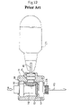
- FIG. 12 shows a conventional medical drilling machine disclosed in Japanese Patent Laid-Open Publication No. Hei 9-19437.
- This medical drilling machine 1 includes: a casing 11 made of X-ray transparent material; a drive shaft 16 housed inside the casing; and a pair of bevel gears 12 , 13 for transferring rotational force to the drive shaft 16 .
- One of the bevel gears 12 is coaxially arranged along the same axis as the drive shaft 16 , and the other bevel gear 13 is provided at one end of an input shaft 15 .
- the input shaft 15 is held in the casing 11 by a bearing 14 .
- the drive shaft 16 and the bevel gears 12 , 13 are also made of X-ray transparent material.
- the drive shaft 16 is held rotatably by two similarly shaped bearings 17 , 18 made of X-ray opaque materials.
- a chuck 20 is provided at one end of the drive shaft 16 , and a drill bit 19 is gripped by the chuck 20 .
- a drive motor 21 is attached to the input shaft 15 .
- X-rays are radiated along the direction in which the bolt hole will be bored (hereinafter, referred to as the “ideal axial line R”).
- the doctor firmly clutches the medical drilling machine 1 in his or her arm, and when the drilling machine enters into an X-ray radiation field T, an image such as shown in FIG. 13 is obtained by the X-rays.
- An axial tip 19 a of the drill bit 19 , an end surface 18 a of the bearing 18 , and the human bone B appear in the X-ray image. Therefore, the bolt hole can be formed in the bone by making the drill bit 19 rotate as the medical drilling machine 1 is advanced forward in a straight direction.
- the doctor When the doctor sees this image, the doctor understands that the drill bit 19 has slanted along a long axis D 1 across the length of the oval ring D. However, there still is a problem in that the doctor can not judge which direction the drill bit 19 is slanting along the long axis D 1 . As a result, the doctor would adjust the direction of the drill bit 19 in the wrong direction, causing the drill hole C to slant even further, or requiring time to adjust the direction of the drill bit 19 , thus creating a problem of lengthening the operation time.
- the present invention has been made to solve the above-mentioned problems, and it is therefore an object of this invention to provide a medical drilling machine that relieves burden to a user such as a doctor, while facilitating the boring of an accurate hole.
- a medical drilling machine includes: a drive shaft held in place in a rotatable fashion, gripping a drill bit by means of a chuck provided to an end of the drive shaft; a casing constituted of X-ray transparent material, being capable of housing the drive shaft; and a force transfer mechanism for transferring rotational force to the drive shaft.
- a first guide and a second guide constituted of X-ray opaque material are fixed at given distances from each other along an axial direction of the drive shaft inside the casing; the first guide and the second guide are arranged coaxially along an axial center of the drive shaft and are formed in mutually different shapes; and X-rays are radiated along a direction of an ideal axial line traveled by the drill bit, such that a slant direction of the drill bit with respect to the ideal axial line can be observed from any relative misalignment of, and the mutually different shapes of, the first and the second guides.
- the inventor of the present invention noticed that it is difficult to observe the accurate slant direction of the drill bit based only on whether outer shape of the two bearings depicted by X-rays matched up with each other or not, as was done in the conventional art. Therefore, the inventor provided the first and the second guides deliberately having the mutually different shapes.
- the user can accurately read the slant direction of the drill bit from the relative misalignment between the first and the second guides.
- the slant of the drill bit can be corrected quickly, to enable formation of the drill hole substantially corresponding to direction of the ideal axial line. This also contributes to alleviation of burden (work) for the doctor or other user.
- first and the second guides are configured having “mutually different shapes”, this means simply that their respective shapes do not completely match each other, and it means that it is sufficient if the guides can be distinguished one from the other when their axial centers become relatively misaligned with each other. Even if they have mutually similar shapes simply formed in different sizes, this is included in the concept of having “mutually different shapes” provided the guides can be mutually distinguished. Additionally, the same is true for example in a case where the guides have similar designs (e.g., as equilateral triangles having sides of equal lengths) but arranged at mutually different phases (e.g., when the topmost angles of the triangles are phased 60° from each other).
- the present invention also includes a case where the images of the guides overlap and the first guide and the second guide cannot be discerned one from the other when the axial centers of the guides are aligned with each other, but their mutually different shapes are emphasized when their axial centers become misaligned.
- the drive shaft is held in a rotatable fashion by means of a first bearing and a second bearing constituted of X-ray transparent material, and predetermined housing portions are formed to non-rotating portions of the first and the second bearings; and X-ray opaque material is inserted into the housing portions of the first and the second bearings to provide the first guide in the first bearing, and provide the second guide in the second bearing.
- housing portions to the inner surfaces of the cylindrical portions for housing the first and the second bearings and to insert X-ray opaque material into the housing portions in order to provide the first guide to the first bearing, and provide the second guide to the second bearing.
- the casing is provided with a drive motor for making the drive shaft rotate via the force transfer mechanism, and a battery for the drive motor. According to this construction, the entire machine becomes a single unit and becomes easier to use, enabling accurate positioning of the drill bit. Therefore, since the above-mentioned first and second guides can be utilized effectively, the slant of the drill bit can be corrected smoothly using on the guides.
- the drive motor is arranged to be displaced from the axial line of the drive shaft, and a motor shaft of the drive motor is arranged in parallel with the axial line, a grip portion is provided as an integral part of the casing, on an opposite side of the drive shaft from the side where the drive motor is located, and the battery is provided to a grip end side of the grip portion.
- the doctor or other user typically holds the medical drilling machine at various angles. Therefore, by adopting the above-mentioned construction the battery, the grip portion, the drill bit (the drive shaft) and the drive motor are lined up one after the other such that the heavier battery and the drive motor are positioned at either end, and the grip portion and the drill bit which function as a fulcrum or point of support are arranged between the battery and the drive motor. Therefore, the balance properties of the device as a whole are excellent, and the drill bit can be positioned quickly by gripping the grip portion, in addition to alleviating the burden on the arm of the doctor or other user.
- the drive motor is arranged to be displaced from the axial line of the drive shaft, and a motor shaft of the drive motor is arranged in parallel with the axial line; a grip portion is provided as an integral part of the casing, on an opposite side of the drive motor from the side where the drive shaft is located; and the battery is provided to a grip end side of the grip portion.
- a drive shaft through-hole is provided along the axial line of the drive shaft, and a casing through-hole is provided to the casing along the line of extension of the drive shaft through-hole; and the back end of the drill bit held by the drive shaft can be housed into both the drive shaft through-hole and the casing through-hole.
- a long drill bit can be used when boring a hole of considerable length along the axial direction into the bone.
- FIG. 1 is an overall constructional view showing a medical drilling machine according to an embodiment of the present invention
- FIG. 2 is a cross-sectional view taken along the line II—II in FIG. 1 ;
- FIG. 3 is a cross-sectional view taken along the line III—III in FIG. 1 ;
- FIG. 4 is a perspective view of an example of the medical drilling machine as it is being used
- FIGS. 5(A) and 5(B) are diagrams showing images produced by X-rays while the medical drilling machine is being used;
- FIG. 6 is a diagram of a bone having been operated on using the medical drilling machine
- FIG. 7 is a schematic view showing weight distribution in the medical drilling machine
- FIGS. 8(A) and (B) are perspective views showing other examples of the medical drilling machine being used.
- FIG. 9 is a schematic view of another example of guides in the medical drilling machine.
- FIG. 10 is a schematic view of yet another example of guides in the medical drilling machine.
- FIG. 11 is a schematic view of yet another example of guides in the medical drilling machine.
- FIG. 12 is an overall view of a conventional medical drill
- FIG. 13 is a diagram showing an image produced by X-rays while the conventional medical drill machine is being used;
- FIG. 14 is a diagram showing another image produced by X-rays while the conventional medical drill machine is being used.
- FIG. 15 is a diagram showing an example of a drill hole bored using the conventional medical drilling machine
- FIG. 1 shows a medical drilling machine (hereinafter, “drill machine”) 100 , in accordance with a first embodiment of the present invention.
- the drill machine 100 includes: a drill bit 102 ; a drive shaft 106 gripping the drill bit 102 by means of a chuck 104 provided at the end of the drive shaft; a casing 108 capable of housing the drive shaft 106 ; and a force transferring mechanism 110 for transferring rotational force to the drive shaft 106 .
- the drive shaft 106 is held rotatably by a first bearing 112 and a second bearing 114 provided inside the casing 108 .
- the drive shaft 106 , both the bearings 112 , 114 , and the casing 108 are made of X-ray transparent material.
- the force transferring mechanism 110 includes: a pinion 110 A provided to a motor shaft of the drive motor 116 ; and a gear 110 B which meshes with the pinion 110 A and is provided integrally around the drive shaft 106 . Therefore, the rotational force from the drive motor 116 is transferred through the pinion 110 A and the gear 110 B to the drive shaft 106 .
- a battery 118 for the drive motor 116 is also attached to the casing 108 .
- the first and the second bearings 112 , 114 are so-called “sliding bearings” shaped as sleeves, as can be seen close-up in FIG. 2 and FIG. 3 .
- Housing portions 112 A, 114 A are provided to non-rotating portions of the first and the second bearings 112 , 114 (however, in a “sliding bearing” the entire bearing is “non-rotating portion”).
- X-ray opaque materials 122 A, 124 A i.e., in the present example metal rods are used
- These X-ray opaque materials 122 A, 124 A constitute a first guide 122 in the first bearing 112 , and a second guide 124 in the second bearing 114 . Note, however, that if rolling bearings are used for the first and the second bearings, then only their outer rings affixed to the casing 108 will serve as the non-rotating portions.
- holes are formed to the outer surfaces of the first and the second bearings 112 , 114 at 90-degree intervals toward the radial center of the shaft.
- the length (depth) of these holes is such that the holes on the second bearing 114 side are longer (deeper) than those on the first bearing 112 side.
- the length of the above-mentioned X-ray opaque materials 122 A, 124 A are substantially the same length as the holes.
- first guide 122 and the second guide 124 are fixed at positions to create a predetermined distance L between the first guide and the second guide, along the drive shaft 106 inside the casing 108 . Further, the first guide 122 and the second guide 124 are positioned along the same axis as the drive axis 106 , but are formed in mutually different shapes.
- the drive motor 116 is arranged at a position displaced from an axial line P of the drive shaft 106 , and its motor axis is arranged parallel to the axial line P. Further, a grip portion 125 formed by a portion of the casing 108 is provided on the opposite side of the drive shaft 106 from the drive motor 116 side.
- the battery 118 is removeably attached to a grip end side of the grip portion 125 .
- the battery 118 is made removeable so that it can be exchanged for a new battery when the residual energy in the battery 118 is exhausted while performing operations. However, of course, the battery 118 may also be housed inside the casing 108 .
- a drive shaft through-hole 106 A is formed to the drive shaft 106 along the axial line P, and a casing through-hole 108 A is formed to the casing 108 along a linear extension from the above-mentioned drive shaft through-hole 106 A (i.e., in alignment with the axial line P).
- the drill bit 102 held by the drive shaft 106 can extend through both the drive shaft through-hole 106 A and the casing through-hole 108 A.
- FIG. 4 shows formation of a bolt hole C into a bone B below the knee of a human body H.
- X-rays are radiated in the direction of an ideal axial line R along which the drill bit 102 is to be advanced.
- An image reception apparatus (not shown in the diagram) is arranged at a place above the human body H along the direction traveled by the X-rays. When the X-rays do not arrive at the other side, this produces shadows of the materials (members) X-rays cannot transmit through.
- the ideal axial line R mentioned above refers to the axial direction along which the doctor plans to form the bolt hole C.
- FIG. 5(A) When the doctor inserts the drill machine 100 into the X-ray radiation field, an image E 1 as shown in FIG. 5(A) is obtained.
- This image E 1 shows, for example, the bone B, bone-setting material D inserted into the bone, an end surface of the drill bit 102 , the first and the second guides 122 , 124 , et cetera.
- the doctor can judge that the ideal axial line R and the drive axis 106 (or the drill bit 102 ) axial line P are, in fact, in alignment. Therefore, if the drill bit 102 is advanced straight forward in this position, the bolt hole C will be formed into the bone B exactly as desired.
- the drill 102 will not advance in a straight line.
- an image E 2 such as shown in FIG. 5(B) will be obtained.
- the first guide 122 and the second guide 124 are misaligned. Since the first guide and the second guide 124 are shaped differently, the doctor can observe the difference in shape, and can observe the slant direction (including the direction of the misalignment) of the drill bit 102 with respect to the ideal axial line R, based on the relative misalignment of the first guide 122 and the second guide 124 . For example, in the image E 2 , the second guide 124 (which is relatively longer) is displaced above the first guide 122 . Therefore, one can judge that the drill bit 102 has slanted upward with respect to the ideal axial line R.
- the slanting direction of the drill bit 102 can be immediately recognized and corrected, in order to bore the hole C substantially in line with the direction of the ideal axial line R.
- the bone-setting material D and the bolt F inserted into the bolt hole C can be firmly connected, for example, as shown in FIG. 6 .
- the structure becomes simple and manufacturing costs are reduced.
- this type of drill machine 100 is held at various angles by the doctor or other user, and it is particularly common for the grip portion 125 to be held horizontally. Therefore, if the machine is not integrally formed as a single unit, or if the weight of the machine is distributed poorly, a large burden is created for doctor.
- the present drill machine 100 in addition to the easy correction of the path traveled by the drill bit 102 by virtue of the guides 122 , 124 , since the drive motor 116 and the battery 118 are formed as a single unit, external wiring or piping or the like are unnecessary. This facilitates complicated handling of the drill machine 100 , and enables better positioning of the drill bit 102 .
- the grip portion 125 is held substantially horizontally, the battery 118 , the grip portion 125 , the drill bit 102 (the drive shaft) and the drive motor 116 are lined up in sequence such that the heavier battery 118 and the drive motor 116 are positioned at either end as shown schematically in FIG. 7 .
- This achieves excellently balanced weight distribution in the machine 100 .
- the burden borne by the arm of the doctor or other user is diminished.
- the present invention is not restricted to the configuration in which the parts are arranged in the sequence shown in FIG. 7 .
- they may be arranged with the battery 118 first, followed by the grip portion 125 , the drive motor 116 , and then the drill bit 102 , so as to give a heavier sense to both ends of the grip portion 125 to improve the weight distribution (this configuration is recited in claim 5 of the present invention).
- the drill bit when forming a relatively long insertion hole in a bone along the axial direction, the drill bit must also be equivalently longer.
- the tip of the drill bit diverges from the axial center when it rotates, whereby the drill bit is likely to drift from the location where the hole is intended.
- the back end of the drill bit 102 can be housed into the drive shaft through-hole 106 A and the casing through-hole 108 A, and furthermore, when the drill bit 102 is particularly long, the drill bit 102 may be passed through these holes 106 A, 108 A so as to protrude out from the rear side.
- the tip can be adjusted to an effective length Y as needed, whereby the long hole can be bored easily.
- the present embodiment showed the case where the fist and the second guides 122 , 124 are formed in mutually different shapes. Therefore, particularly when the direction of the ideal axial line R and the axial line P of the drive shaft 106 are aligned with each other, the images of the first and the second guides 122 , 124 overlap each other.
- the “mutually different shape” of the guides 122 , 124 can also include a configuration in which the images of the guides 122 , 124 do not overlap each other, and can thus be distinguished from each other at all times.
- both the first guide 122 and the second guide 124 are formed as rings. Even if the only difference between the two guides 122 , 124 is their relative sizes (i.e., even if they have the same shape), they can be distinguished from one another; therefore, this is included in the concept of the two guides 122 , 124 having “mutually different shapes.” Furthermore, this also includes a case such as shown in FIG. 10 , in which the first and the second guides 122 , 124 are formed as equilateral triangles of the same size arranged in different phase positions.
- the present embodiment illustrated the case where the guides 122 , 124 are provided inside the bearings 112 , 114 .
- the housing portions may be provided to cylinder portions 112 B, 114 B which hold the bearings 112 , 114 in place in the casing 108 , and the guides 122 , 124 may be inserted into the housing portions.
- the guides 122 , 124 may also be provided to yet another location.
- the present invention facilitates the positioning of the drill bit, and enables accurate boring of the hole.
Landscapes
- Health & Medical Sciences (AREA)
- Life Sciences & Earth Sciences (AREA)
- Surgery (AREA)
- Nuclear Medicine, Radiotherapy & Molecular Imaging (AREA)
- Biomedical Technology (AREA)
- Molecular Biology (AREA)
- Oral & Maxillofacial Surgery (AREA)
- Engineering & Computer Science (AREA)
- Dentistry (AREA)
- Heart & Thoracic Surgery (AREA)
- Medical Informatics (AREA)
- Orthopedic Medicine & Surgery (AREA)
- Animal Behavior & Ethology (AREA)
- General Health & Medical Sciences (AREA)
- Public Health (AREA)
- Veterinary Medicine (AREA)
- Pathology (AREA)
- Radiology & Medical Imaging (AREA)
- Surgical Instruments (AREA)
Abstract
Description
Claims (12)
Applications Claiming Priority (2)
| Application Number | Priority Date | Filing Date | Title |
|---|---|---|---|
| JP2001-25964 | 2001-02-01 | ||
| JP2001025964A JP2002224125A (en) | 2001-02-01 | 2001-02-01 | Medical drilling machine |
Publications (2)
| Publication Number | Publication Date |
|---|---|
| US20040138667A1 US20040138667A1 (en) | 2004-07-15 |
| US7074225B2 true US7074225B2 (en) | 2006-07-11 |
Family
ID=18890867
Family Applications (1)
| Application Number | Title | Priority Date | Filing Date |
|---|---|---|---|
| US10/637,024 Expired - Fee Related US7074225B2 (en) | 2001-02-01 | 2003-08-08 | Medical drilling machine |
Country Status (2)
| Country | Link |
|---|---|
| US (1) | US7074225B2 (en) |
| JP (1) | JP2002224125A (en) |
Cited By (4)
| Publication number | Priority date | Publication date | Assignee | Title |
|---|---|---|---|---|
| US20110166447A1 (en) * | 2008-09-03 | 2011-07-07 | Ao Technology Ag | Device for manipulating a bone or bone fragment or a surgical instrument, tool or implant and a method for positioning such a device |
| US8465491B2 (en) * | 2006-06-01 | 2013-06-18 | Osteo Innovations Llc | Bone drill |
| US20140262408A1 (en) * | 2013-03-15 | 2014-09-18 | Vidacare Corporation | Drivers and Drive System |
| US9216048B2 (en) | 2009-03-18 | 2015-12-22 | Integrated Spinal Concepts, Inc. | Image-guided minimal-step placement of screw into bone |
Families Citing this family (12)
| Publication number | Priority date | Publication date | Assignee | Title |
|---|---|---|---|---|
| JP2002224125A (en) | 2001-02-01 | 2002-08-13 | Nippon Yunitekku:Kk | Medical drilling machine |
| JP5431749B2 (en) * | 2009-03-04 | 2014-03-05 | テルモ株式会社 | Medical manipulator |
| JP5388106B2 (en) * | 2009-03-12 | 2014-01-15 | HOYA Technosurgical株式会社 | Medical drill equipment |
| KR101754138B1 (en) * | 2010-01-13 | 2017-07-05 | 제이씨비디, 엘엘씨 | Sacroiliac joint fixation fusion system |
| JP2013066562A (en) * | 2011-09-21 | 2013-04-18 | Kyocera Medical Corp | Extractor |
| US10070873B2 (en) * | 2014-06-30 | 2018-09-11 | Tornier, Inc. | Device for maintaining alignment of a cannulated shaft over a guide pin |
| US10390843B1 (en) * | 2015-02-03 | 2019-08-27 | Dartmouth-Hitchcock Clinic | Trajectory and aiming guide for use with fluoroscopy |
| ITUB20153646A1 (en) * | 2015-09-15 | 2017-03-15 | Sim Soluzioni Innovative Medicali Sagl | Guide device for the insertion of locking means for an intramedullary nail |
| CN110742673B (en) * | 2018-07-24 | 2021-03-16 | 上海库欣医疗科技有限公司 | Electric bone drill |
| CN109077777B (en) * | 2018-10-19 | 2024-05-17 | 北京天星博迈迪医疗器械有限公司 | Depth-controllable drilling device and drill bit assembly thereof |
| KR101993206B1 (en) * | 2018-12-05 | 2019-09-30 | 의료법인 명지의료재단 | Medical drill device for recognizing bend of drill bit |
| CN111839655B (en) * | 2020-07-24 | 2022-05-20 | 中南大学湘雅医院 | Multistage guiding and positioning type electric bone drill |
Citations (6)
| Publication number | Priority date | Publication date | Assignee | Title |
|---|---|---|---|---|
| JPH01501207A (en) | 1986-09-23 | 1989-04-27 | リスト,ハインツ―ユールゲン | surgical bone drilling machine |
| JPH053882A (en) | 1990-02-07 | 1993-01-14 | Smith & Nephew Richards Inc | Guide system for surgical instrument |
| JPH0919437A (en) | 1995-07-05 | 1997-01-21 | Japan Medical Dynamic Marketing Inc | Medical drill device |
| JPH1075960A (en) | 1996-09-02 | 1998-03-24 | Osada Res Inst Ltd | Wire driver hand piece |
| JPH11244300A (en) | 1997-12-19 | 1999-09-14 | Mtg Divestitures Inc | Guide pin arrangement device and method of using the same |
| JP2002224125A (en) | 2001-02-01 | 2002-08-13 | Nippon Yunitekku:Kk | Medical drilling machine |
-
2001
- 2001-02-01 JP JP2001025964A patent/JP2002224125A/en active Pending
-
2003
- 2003-08-08 US US10/637,024 patent/US7074225B2/en not_active Expired - Fee Related
Patent Citations (6)
| Publication number | Priority date | Publication date | Assignee | Title |
|---|---|---|---|---|
| JPH01501207A (en) | 1986-09-23 | 1989-04-27 | リスト,ハインツ―ユールゲン | surgical bone drilling machine |
| JPH053882A (en) | 1990-02-07 | 1993-01-14 | Smith & Nephew Richards Inc | Guide system for surgical instrument |
| JPH0919437A (en) | 1995-07-05 | 1997-01-21 | Japan Medical Dynamic Marketing Inc | Medical drill device |
| JPH1075960A (en) | 1996-09-02 | 1998-03-24 | Osada Res Inst Ltd | Wire driver hand piece |
| JPH11244300A (en) | 1997-12-19 | 1999-09-14 | Mtg Divestitures Inc | Guide pin arrangement device and method of using the same |
| JP2002224125A (en) | 2001-02-01 | 2002-08-13 | Nippon Yunitekku:Kk | Medical drilling machine |
Cited By (11)
| Publication number | Priority date | Publication date | Assignee | Title |
|---|---|---|---|---|
| US8465491B2 (en) * | 2006-06-01 | 2013-06-18 | Osteo Innovations Llc | Bone drill |
| US20110166447A1 (en) * | 2008-09-03 | 2011-07-07 | Ao Technology Ag | Device for manipulating a bone or bone fragment or a surgical instrument, tool or implant and a method for positioning such a device |
| US9119641B2 (en) * | 2008-09-03 | 2015-09-01 | Ao Technology Ag | Device for manipulating a bone or bone fragment or a surgical instrument, tool or implant and a method for positioning such a device |
| US9216048B2 (en) | 2009-03-18 | 2015-12-22 | Integrated Spinal Concepts, Inc. | Image-guided minimal-step placement of screw into bone |
| US9687306B2 (en) | 2009-03-18 | 2017-06-27 | Integrated Spinal Concepts, Inc. | Image-guided minimal-step placement of screw into bone |
| US10603116B2 (en) | 2009-03-18 | 2020-03-31 | Integrated Spinal Concepts, Inc. | Image-guided minimal-step placement of screw into bone |
| US11471220B2 (en) | 2009-03-18 | 2022-10-18 | Integrated Spinal Concepts, Inc. | Image-guided minimal-step placement of screw into bone |
| US20140262408A1 (en) * | 2013-03-15 | 2014-09-18 | Vidacare Corporation | Drivers and Drive System |
| US9615816B2 (en) * | 2013-03-15 | 2017-04-11 | Vidacare LLC | Drivers and drive systems |
| US10716582B2 (en) | 2013-03-15 | 2020-07-21 | Teleflex Life Sciences Limited | Drivers and drive systems |
| US11737765B2 (en) * | 2013-03-15 | 2023-08-29 | Teleflex Life Sciences Limited | Drivers and drive systems |
Also Published As
| Publication number | Publication date |
|---|---|
| JP2002224125A (en) | 2002-08-13 |
| US20040138667A1 (en) | 2004-07-15 |
Similar Documents
| Publication | Publication Date | Title |
|---|---|---|
| US7074225B2 (en) | Medical drilling machine | |
| US7226456B2 (en) | Trackable medical tool for use in image guided surgery | |
| CN103998093B (en) | Lead an orientation tool | |
| EP3137249B1 (en) | Rotary tool with improved coupling assembly | |
| US20050038443A1 (en) | Surgical tools for joint replacement | |
| JP6949021B2 (en) | Surgical instrument with telescopic nose mechanism | |
| US9066730B2 (en) | Medical device | |
| US8157563B2 (en) | Guide device able to interact with a number of sleeves disposed in a tooth template | |
| KR101595597B1 (en) | Cutting accessory for use with a surgical handpiece, the accessory having features that faciltiate the coarse or fine adjustment of the accessory shaft | |
| EP2364652B1 (en) | Remotely operated actuator | |
| JP2000070283A (en) | Surgical handpiece with driving power adjustable in angle | |
| US20080058804A1 (en) | Precision Assembleable Surgical Tool Handle with Limited-Play Interconnect Mechanism | |
| JP6812362B2 (en) | System for orthopedic implant preparation | |
| US20200078130A1 (en) | Tool placement manipulator | |
| JP2019126725A (en) | Adaptor for use with driver, drill and cannula for drilling into bone | |
| ES2269731T3 (en) | DRILLING TOOL. | |
| EP0650793A1 (en) | Keyless drill Chuck | |
| US11331112B2 (en) | Adjustable depth limiting drill guide and suture transporting method | |
| JP2019512285A (en) | Apparatus for sterile coupling of a percutaneous surgical instrument and drive tool and method of performing such coupling | |
| EP2567667A1 (en) | Treatment tool | |
| CN211156474U (en) | Medical implant delivery device | |
| CN107847234A (en) | Orthopaedic instrumentation | |
| CN102579105A (en) | Tubular holder for holding tail end of mechanical arm of holding bone drill | |
| JP5388106B2 (en) | Medical drill equipment | |
| CN215384368U (en) | Bone file switching device for hip joint |
Legal Events
| Date | Code | Title | Description |
|---|---|---|---|
| AS | Assignment |
Owner name: JAPAN UNIVERSAL TECHNOLOGIES, INC., JAPAN Free format text: ASSIGNMENT OF ASSIGNORS INTEREST;ASSIGNOR:KIMURA, JUNICHI;REEL/FRAME:014861/0180 Effective date: 20031208 |
|
| FPAY | Fee payment |
Year of fee payment: 4 |
|
| AS | Assignment |
Owner name: HOYA TECHNOSURGICAL CORPORATION, JAPAN Free format text: CHANGE OF NAME;ASSIGNOR:JAPAN UNIVERSAL TECHNOLOGIES, INC.;REEL/FRAME:031915/0304 Effective date: 20131001 |
|
| FPAY | Fee payment |
Year of fee payment: 8 |
|
| FEPP | Fee payment procedure |
Free format text: PAYOR NUMBER ASSIGNED (ORIGINAL EVENT CODE: ASPN); ENTITY STATUS OF PATENT OWNER: LARGE ENTITY |
|
| FEPP | Fee payment procedure |
Free format text: MAINTENANCE FEE REMINDER MAILED (ORIGINAL EVENT CODE: REM.) |
|
| LAPS | Lapse for failure to pay maintenance fees |
Free format text: PATENT EXPIRED FOR FAILURE TO PAY MAINTENANCE FEES (ORIGINAL EVENT CODE: EXP.) |
|
| STCH | Information on status: patent discontinuation |
Free format text: PATENT EXPIRED DUE TO NONPAYMENT OF MAINTENANCE FEES UNDER 37 CFR 1.362 |
|
| FP | Lapsed due to failure to pay maintenance fee |
Effective date: 20180711 |