US7073403B2 - Method and apparatus for the collection of samples - Google Patents
Method and apparatus for the collection of samples Download PDFInfo
- Publication number
- US7073403B2 US7073403B2 US10/988,915 US98891504A US7073403B2 US 7073403 B2 US7073403 B2 US 7073403B2 US 98891504 A US98891504 A US 98891504A US 7073403 B2 US7073403 B2 US 7073403B2
- Authority
- US
- United States
- Prior art keywords
- sampling
- sampler
- gas
- sampling tubes
- tubes
- Prior art date
- Legal status (The legal status is an assumption and is not a legal conclusion. Google has not performed a legal analysis and makes no representation as to the accuracy of the status listed.)
- Expired - Lifetime, expires
Links
Images


Classifications
-
- G—PHYSICS
- G08—SIGNALLING
- G08B—SIGNALLING OR CALLING SYSTEMS; ORDER TELEGRAPHS; ALARM SYSTEMS
- G08B21/00—Alarms responsive to a single specified undesired or abnormal condition and not otherwise provided for
- G08B21/02—Alarms for ensuring the safety of persons
- G08B21/12—Alarms for ensuring the safety of persons responsive to undesired emission of substances, e.g. pollution alarms
- G08B21/14—Toxic gas alarms
Definitions
- This invention relates to methods and devices to confirm the presence or absence of a chemical agent after a monitor for the detection of that agent alarms.
- NRT near-real-time
- TWA sub time weighted average
- NRT confirmation techniques in current use typically employ a depot area air monitoring system (DAAMS tube) for the collection of confirmation samples.
- the DAAMS system uses solid sorbents packed within a glass or stainless steel tube to collect the sample. The sample is then thermally desorbed into a gas chromatograph for separation and detection.
- Use of the DAAMS system is advantageous in that it allows the trapping and concentration of a large volume sample in a single sampling tube without the use of trapping solvents that would otherwise dilute the sample.
- the DAAMS tubes are reusable and generate virtually no waste.
- Major disadvantages of the DAAMS system are that it requires unique and proprietary automatic thermal desorption equipment for sample introduction and that the entire sample is consumed during the analysis, thus precluding multiple or repeat analysis of a sample.
- the TWA concentrations for most chemical agents require that the NRT monitor operate at its maximum achievable sensitivity and selectivity and its minimum cycle time. Consequently, there are a number of parameters that affect the efficacy of NRT confirmation monitoring. Among those parameters are the sampling rate and the kind or type of sampling that is conducted.
- the sampling rate for a NRT confirmation system is dependent upon the sensitivity of the method used to analyze the confirmation sample. Sensitivity of the confirmation analysis is typically no better than is that of the NRT monitor. Hence, the sampling rate for the confirmation sampler needs to be as high if not higher than the sampling rate for the NRT sampler.
- the NRT monitor In on-demand sampling, the NRT monitor is used to control the operation of a confirmation sampler placed at the same location. When the NRT monitor generates an alarm, it also produces a signal that turns on, or energizes, the confirmation sampler.
- the confirmation sampler employs three DAAMS tubes. The confirmation sampler, upon receiving an alarm signal from the NRT monitor, draws air through the first DAAMS tube for a pre-set time period, typically about fifteen minutes. If the NRT monitor is still in alarm status at the end of the first sampling period, the confirmation sampler sequences to the second DAAMS tube. Otherwise, the confirmation sampler waits for the next alarm event that is captured with the next tube in the sequence. That mode of operation continues until all three DAAMS tubes have been used or the tubes have been collected and the sampler reset.
- On-demand sampling also has unique advantages and disadvantages.
- One advantage is the near elimination of contaminant or interferent buildup on the tube as well as the accumulation of chemical agent that is present in the atmosphere at levels below the detectability limit of the NRT monitor.
- the pump used to draw sample through the DAAMS tubes operates only when an alarm event is suspected, thus considerably increasing pump life. Logistical difficulties and concerns associated with changing out DAAMS tubes in the field are reduced as well.
- a primary disadvantage to on-demand sampling that the atmosphere which causes the NRT monitor to trigger an alarm is not sampled by the confirmation sampler. Rather, the sampled atmosphere is that one present a short time, a few minutes, after the triggering event. That circumstance opens the possibility of being unable to confirm a transient, or single cycle, event.
- An improved confirmation sampler for an analytical monitor employs at least a pair of sorbent-packed sample tubes that sample and purge out of phase one with the other. While one tube is sampling, the other tube is purging to remove any contaminants collected during its sampling cycle.
- the sampler includes control means that synchronize its operation with that of the monitor so that when the monitor is sampling so also is one of the tubes of the confirmation sampler.
- An alarm generated by the monitor upon detection of a chemical agent or other compound of interest causes the confirmation sampler to retain and not desorb the tube that was collected for that particular cycle, leaving it available for retrieval and analysis. If an alarm is not generated upon completion of a particular monitor cycle, sampling by the confirmation sampler is initiated upon the start of the next monitor cycle using the other sample tube.
- the first tube is simultaneously desorbed to remove any contaminants that may have been collected during its sampling cycle and to ready it for reuse.
- FIG. 1 is a generally schematic view depicting the arrangement of an NRT monitor and a confirmation sampler arranged in accordance with this invention
- FIG. 2 is a schematic view showing the components of the confirmation sampler of this invention in a first sampling configuration
- FIG. 3 is a schematic view of the sampler of FIG. 2 in a second sampling configuration
- FIG. 4 is a depiction of the timing cycles of the NRT monitor and confirmation sampler
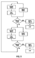
- FIG. 5 is a decision flow chart of the sampling system of this invention.
- FIG. 6 is another embodiment of the confirmation sampler of this invention.
- FIG. 7 is an alternative embodiment of the sampler that is shown in FIG. 6 ;
- FIG. 8 is yet another embodiment of the FIG. 6 sampler.
- System 10 includes a NRT monitor 12 and a confirmation sampler 14 .
- Monitor 12 and sampler 14 are arranged to draw common samples of ambient air or other gaseous atmosphere from a source 16 by way of sample lines 17 and 18 .
- Monitor 12 is arranged to generate an alarm signal 21 upon detection of a chemical agent and, at the same time, to send a signal 23 to sampler 14 .
- Signal 23 causes sampler 14 to retain the just-taken sample in a manner that will be described in detail later.
- the NRT monitor also generates another signal 25 _separate from the alarm signal.
- Signal 25 marks the start of an NRT monitor cycle
- _and confirmation sampler 14 uses that signal to synchronize the initiation of its own sampling cycle.
- sampler 14 includes two four-port, two-position valves 31 , 32 .
- Two sampling tubes, 34 , 35 are arranged in communication with the two valves in a manner to be described in more detail.
- FIG. 2 shows the valves 31 , 32 in a first position whereat tube 34 is in sampling position
- FIG. 3 shows the valves 31 , 32 in a second position whereat tube 35 is in sampling position.
- valve 31 a flowing sample from the source of air or gas being monitored is introduced into valve 31 by way of sample introduction line 18 .
- Valve 31 in its first position, routes the sample out of the valve by way of line 39 into and through sample tube 34 where the chemical agent, if present, is captured by a solid sorbent packed within the tube.
- Tubes 34 and 35 are preferably standard DAAMS tubes, but may be any other sorbent-packed sample tube.
- the solid sorbent packed within the tubes may be, for example, alumina, silica, activated carbon, a molecular sieve or other sorbent depending upon the properties of the chemical agent being monitored.
- Vacuum pump 44 After leaving tube 34 , the gas sample is routed via line 41 through valve 32 and passes by way of exit line 43 to the inlet of a vacuum pump_ 44 .
- Vacuum pump 44 in turn,_exhausts the air or other gas that is being sampled into a mass flow controller 45 _which sets the rate at which pump 44 draws gas through the system. Controller 45 then discharges the sampled gas back to the atmosphere by way of discharge line 47 .
- tube 35 While a gas sample is passing through tube 34 , tube 35 is being purged to remove any chemical agent, contaminant or interferent that might have been captured on the tube packing during a previous sampling. Purging, or regeneration, is accomplished by flowing a heated purge gas through the system by way of line 49 and valve 32 and through sample tube 35 and to valve 31 via conduit 50 . The gas is then discharged to atmosphere after passing through an optional charcoal trap 51 that captures any purged compounds desorbed from tube 35 .
- the purge gas is preferably an inert gas such as nitrogen or helium. In those installations where the confirmation sampler is conveniently located in relation to the NRT monitor the inert purge gas used by the NRT monitor can be shared with the purge gas for the confirmation sampler.
- Sample tubes 34 and 35 are provided with heat exchange means 55 and 57 respectively to heat the tubes and the purge gas passing therethrough to temperatures at which thermal desorption proceeds.
- Heat exchange means 55 and 57 may also serve to cool the tubes after desorption and, using a thermoelectric cooler, it is possible to achieve both heating and cooling using a single element.
- the purge gas may be heated prior its entry into the sample tubes using heat exchange means 53 that is located upstream of the sample tubes.
- Means 53 may comprise any conventional heating means or may comprise a thermoelectric cooler that can provide a heated gas stream to desorb the tube and a colder gas stream to cool the tube after desorption has been completed. Sub ambient cooling allows faster cycle times since the tube can be brought down to its sampling temperature more rapidly than if allowed to cool in an ambient temperature gas stream.
- FIG. 3 illustrates the system with valves 31 and 32 in the second position that serves to reverse the flow paths of gas through the system.
- valve 31 routes the incoming sample in line 47 through sample tube 35 by way of line 50 , and then to valve 32 , vacuum pump 44 and mass flow controller 45 .
- a heated purge gas stream 49 is passed through sample tube 34 to valve 31 , and out of the system through charcoal trap 51 .
- the confirmation sampling system of this invention includes two, sorbent-packed sample tubes, preferably DAAMS tubes, which alternately sample the local atmosphere that is being monitored. While one tube is sampling, the other tube is purging to remove any contaminants collected during its sampling cycle. That sampling cycle is synchronized with the sampling cycle of the NRT monitor so that a confirmation sample is taken contemporaneously with each sample taken by the NRT monitor. If an alarm is generated by the NRT monitor, the confirmation sample for that cycle is not desorbed, and is therefore available for retrieval and analysis.
- two, sorbent-packed sample tubes preferably DAAMS tubes, which alternately sample the local atmosphere that is being monitored. While one tube is sampling, the other tube is purging to remove any contaminants collected during its sampling cycle. That sampling cycle is synchronized with the sampling cycle of the NRT monitor so that a confirmation sample is taken contemporaneously with each sample taken by the NRT monitor. If an alarm is generated by the NRT monitor, the confirmation sample for that cycle is not desorbed, and is therefore available for retrieval and analysis.
- FIG. 4 The manner in which the timing cycles of the NRT monitor and the confirmation sampler are coordinated is schematically illustrated in FIG. 4 .
- That Figure shows three cycles of the NRT monitor, designated along the bottom time line as cycles a, b, and c.
- a timing signal 25 at the beginning of each monitor cycle synchronizes the cycle of the confirmation sampler with that of the monitor.
- the top time line depicts the condition of sample tube 34
- the middle time line depicts the condition of sample tube 35 over that same three-cycle time period.
- the NRT monitor first draws a gas sample through a sorbent-packed sample tube for a predetermined period of time, then desorbs any chemical compounds captured during the sampling into an analyzer which may be a gas chromatograph, mass spectrometer, or other suitable analytical device to determine whether or not the chemical agent being monitored is present. In the meantime, a portion of the same gas stream sampled by the NRT monitor is passed through sample tube 34 .
- the confirmation sampler constantly polls the NRT monitor to see if an alarm has been generated. If the NRT analyzer reports the presence of the chemical agent that is being monitored, it sounds an alarm and the system proceeds in the manner diagrammed in FIG. 5 .
- the NRT monitor fails to detect the presence of the chemical agent, it begins a new cycle, cycle b, of sampling, desorbing and analyzing.
- cycle b tube 34 is first desorbed and is then cooled to prepare it to again sample the gas stream during cycle c.
- tube 35 is sampling and, if the NRT monitor fails to alarm, tube 35 is then desorbed and cooled during cycle c to prepare it to again sample during the following cycle.
- the cycles a, b, and c repeat endlessly.
- FIG. 5 sets out a logic diagram that illustrates the control decisions that govern operation of the confirmation sampling system of this invention over a complete operating cycle.
- a representative portion of the atmosphere being monitored is passed through the first sample tube, tube 35 , in synchronization with the sampling cycle of the NRT monitor.
- the confirmation sampler continuously polls the NRT monitor to see whether an alarm signal is generated by the monitor. If an alarm is generated, indicating that the chemical agent of concern is present, tube 35 is not desorbed but instead is preserved for retrieval and confirmation analysis.
- a second, follow-on sample is then obtained using the second sample tube, tube 34 . As soon as the tube 34 sample is finished the system stops, preserving both the concurrently taken sample 35 and the follow-on sample 34 for retrieval and analysis.
- more than two samples may be collected and preserved after the NRT monitor generates an alarm so as to obtain a more complete record of the triggering event.
- FIG. 6 illustrates another embodiment of the confirmation sampler 14 of this invention.
- Sampler 14 in this embodiment, includes a four-port, two-position valve 61 , a two-port, two-position valve 63 , and four check valves 64 , 65 , 66 , and 67 .
- Two sampling tubes, 34 , 35 are arranged in association with the valves in a manner that will be further described.
- FIG. 6 shows valve 61 in a first position whereat tube 34 is in a sampling position.
- vacuum pump 71 pulls a flowing sample of the air or other gas that is being monitored through line 18 that is connected to the sample source.
- the sample is pulled first through check valve 64 , which opens under the pressure of the sample gas, and then through sampling tube 34 .
- Sample gas exiting from tube 34 is directed through heater 73 (which is off while tube 34 is sampling), through valve 61 , and then to the inlet side of pump 71 .
- Sampling rate is monitored and controlled by means of a flow meter/controller 75 located just downstream of pump 71 .
- Check valves 66 and 67 remain closed under the positive pressure of gas exiting flow meter 75 causing the gas exhaust through line 77 .
- Sample tube 35 is desorbed, or purged, during a part of the time that tube 34 is in a sampling position.
- Valve 63 controls the flow of purge gas from supply line 49 .
- the purge gas may be air, nitrogen, or other suitable gas.
- Valve 61 directs the purge gas flow through heater 79 and then through sampling tube 35 in a direction counter to that of the gas flow during sampling.
- Hot purge gas, now containing contaminants that were sorbed onto the packing of sampling tube 35 exits from heater 79 and causes check valve 66 to open while check valves 65 and 67 remain closed. The opening of check valve 66 provides a path for the purge gas to exhaust through line 77 .
- tube 35 is first purged and then cooled during the time that sample gas is passing through tube 34 . Cooling of the sampling tube and its sorbent packing is necessary to prepare it for its sampling cycle, and cooling is accomplished by turning heater 79 to its off position while continuing the flow of purge gas through heater 79 and tube 35 . It is possible to shorten the time required for cooling tube 35 by refrigerating the purge gas before its entry into tube 35 , but refrigeration is not ordinarily required for satisfactory operation.
- valve 61 At the end of a predetermined time period, valve 61 is caused to move from its first to its second position, thus starting a new cycle in a fashion that is more completely described in the discussion of FIGS. 4 and 5 .
- sample gas passes from source 18 , through check valve 65 and into sample tube 35 .
- Gas exiting tube 35 passes through heater 79 (which is off during the time that tube 35 is in a sampling position), through valve 61 and into vacuum pump 71 .
- gas exiting pump 71 is directed through flow controller 75 and closed check valves 66 and 67 cause the gas to exhaust at 77 .
- valve 63 allows purge gas to flow through heater 73 , sampling tube 34 , and then out of the system by way of check valve 67 and exhaust 77 .
- Heater 73 is in its on position during the desorption of contaminants from the packing of sampling tube 34 . That cycle repeats endlessly until the NRT analyzer reports the presence of the chemical agent being monitored, at which time the system proceeds in the manner diagrammed in FIG. 5 .
- FIG. 7 illustrates an alternative embodiment of the FIG. 6 sampler.
- This embodiment includes the same arrangement of a four-port, two-position valve 61 , a two-port, two-position valve 63 , four check valves 64 , 65 , 66 , and 67 , and a pair of sampling tubes 34 , 35 as does the FIG. 6 embodiment.
- FIG. 7 shows valve 63 in a first position whereat tube 34 is in a sampling position.
- vacuum pump 71 pulls a flowing sample of the air or other gas that is being monitored through line 18 that is connected to the sample source. The sample is pulled first through check valve 64 , which opens under the pressure of the sample gas, and then through sampling tube 34 .
- Sample gas exiting from tube 34 is directed through heater 73 (which is off while tube 34 is sampling), through valve 61 , and then to the inlet side of pump 71 .
- Sampling rate is monitored and controlled by means of a flow meter/controller 75 located just downstream of pump 71 .
- Check valves 66 and 67 remain closed under the positive pressure of gas exiting flow meter 75 causing the gas to exhaust through line 77 .
- Sample tube 35 is desorbed, or purged, during a part of the time that tube 34 is in a sampling position.
- Valve 63 controls the flow of purge gas from supply line 49 .
- the purge gas may be air, nitrogen, or other suitable gas.
- Valve 61 directs the purge gas flow through heater 79 and then through sampling tube 35 in a direction counter to that of the gas flow during sampling.
- Hot purge gas, now containing contaminants that were sorbed onto the packing of sampling tube 35 exits from heater 79 and causes check valve 66 to open while check valves 65 and 67 remain closed. The opening of check valve 66 provides a path 79 separate from the purge gas exhaust stream 77 .
- Stream 79 is then directed to an analytical instrument (not shown) such as a gas chromatograph, infrared detector, or mass spectrometer. It is preferred that the entire path between the sample tube exit and the entry port of the analytical instrument be heated in order to avoid any condensation of the analyte on the tube walls.
- an analytical instrument such as a gas chromatograph, infrared detector, or mass spectrometer. It is preferred that the entire path between the sample tube exit and the entry port of the analytical instrument be heated in order to avoid any condensation of the analyte on the tube walls.
- This sampler embodiment may also be used as a stand-alone sampling device, in addition to its use as a confirmation sampler, by incorporation of a timer 81 into the system to generate a control signal 82 that causes valve 61 to toggle between its two positions. Maintaining the interval between timer signals constant fixes the same size because the flow rate through the sample tubes is controlled by means 75 . That will permit a quantitative, rather than simply qualitative, analysis to be performed.
- FIG. 8 Yet another embodiment of the FIGS. 6 and 7 samplers is shown in FIG. 8 .
- pump 71 is arranged downstream from flow meter/controller 75 , and sample tube heaters 85 and 86 replace purge gas heaters 73 and 74 of the other embodiments.
- pump 71 be an electric motor driven, diaphragm pump. Electric motors powering such pumps typically have a low starting torque, and are unable to start the pump against the back pressure which develops if power to the system is interrupted during operation.
- a two-port, two-position solenoid valve 88 is arranged such that it is in an open position as shown upon loss of power to pump 77 .
- valve 61 may be controlled by means of a timer to allow operation of the system as a stand-alone sampling device.
Landscapes
- Health & Medical Sciences (AREA)
- General Health & Medical Sciences (AREA)
- Toxicology (AREA)
- Engineering & Computer Science (AREA)
- Environmental & Geological Engineering (AREA)
- Business, Economics & Management (AREA)
- Emergency Management (AREA)
- Physics & Mathematics (AREA)
- General Physics & Mathematics (AREA)
- Sampling And Sample Adjustment (AREA)
Abstract
Description
Claims (15)
Priority Applications (1)
| Application Number | Priority Date | Filing Date | Title |
|---|---|---|---|
| US10/988,915 US7073403B2 (en) | 2002-10-03 | 2004-11-15 | Method and apparatus for the collection of samples |
Applications Claiming Priority (2)
| Application Number | Priority Date | Filing Date | Title |
|---|---|---|---|
| US10/263,584 US6819253B2 (en) | 2001-10-05 | 2002-10-03 | Method and apparatus for the collection of near real time confirmation samples |
| US10/988,915 US7073403B2 (en) | 2002-10-03 | 2004-11-15 | Method and apparatus for the collection of samples |
Related Parent Applications (1)
| Application Number | Title | Priority Date | Filing Date |
|---|---|---|---|
| US10/263,584 Continuation-In-Part US6819253B2 (en) | 2001-10-05 | 2002-10-03 | Method and apparatus for the collection of near real time confirmation samples |
Publications (2)
| Publication Number | Publication Date |
|---|---|
| US20050092109A1 US20050092109A1 (en) | 2005-05-05 |
| US7073403B2 true US7073403B2 (en) | 2006-07-11 |
Family
ID=34549051
Family Applications (1)
| Application Number | Title | Priority Date | Filing Date |
|---|---|---|---|
| US10/988,915 Expired - Lifetime US7073403B2 (en) | 2002-10-03 | 2004-11-15 | Method and apparatus for the collection of samples |
Country Status (1)
| Country | Link |
|---|---|
| US (1) | US7073403B2 (en) |
Cited By (5)
| Publication number | Priority date | Publication date | Assignee | Title |
|---|---|---|---|---|
| US20090031827A1 (en) * | 2007-08-05 | 2009-02-05 | University Of Kuwait | Smart sample Extraction Device and Method |
| US20100011843A1 (en) * | 2006-04-20 | 2010-01-21 | Kenneth Graham Smith | Particle monitor |
| US20110154918A1 (en) * | 2009-12-30 | 2011-06-30 | Syage Jack A | Surface sampling mobile chemical detection probe |
| US8863595B2 (en) | 2007-08-05 | 2014-10-21 | Kuwait University | Sample extraction device |
| US9296540B1 (en) | 2012-12-06 | 2016-03-29 | Randall Stuart Fike | Sorbent holder system for storage or transport having a cleansing element |
Families Citing this family (7)
| Publication number | Priority date | Publication date | Assignee | Title |
|---|---|---|---|---|
| US10006891B2 (en) * | 2009-11-25 | 2018-06-26 | Flir Detection, Inc. | Analytical instrumentation, analytical instrument assemblies, and analytical methods |
| US9250218B2 (en) | 2009-12-07 | 2016-02-02 | S.T.I. Security Technology Integration Ltd. | Method and apparatus for inspecting a gas sample |
| GB201314252D0 (en) | 2013-08-08 | 2013-09-25 | Smiths Detection Watford Ltd | Apparatus and method |
| CN107807209B (en) * | 2017-11-20 | 2024-05-14 | 北京国网富达科技发展有限责任公司 | Micro-water density monitoring device for gas |
| WO2019169121A1 (en) * | 2018-02-28 | 2019-09-06 | Mls Acq, Inc. D/B/A Max Analytical Technologies | Thermal desorption tube collection system and method |
| CN109655564A (en) * | 2019-01-18 | 2019-04-19 | 武汉市天虹仪表有限责任公司 | A kind of two-way continuous sample introduction device and method |
| CN111435127A (en) * | 2019-08-10 | 2020-07-21 | 北京高斯匹克技术有限公司 | Online analysis system for organic matters in air |
Citations (11)
| Publication number | Priority date | Publication date | Assignee | Title |
|---|---|---|---|---|
| US1559461A (en) * | 1921-05-28 | 1925-10-27 | Ruben Samuel | Gas and vapor indicating device |
| US5259233A (en) * | 1991-04-24 | 1993-11-09 | American Air Liquide | Counterflow valve |
| US5325705A (en) * | 1990-12-14 | 1994-07-05 | Novapure Corporation | In-line detector system for real-time determination of impurity concentration in a flowing gas stream |
| US5542284A (en) * | 1994-10-18 | 1996-08-06 | Queen's University At Kingston | Method and instrument for measuring differential oxygen concentration between two flowing gas streams |
| US5770793A (en) * | 1996-02-24 | 1998-06-23 | Dragerwerk Aktiengesellschaft | Method for determining the concentration of a substance in a gas |
| US5961936A (en) * | 1996-12-12 | 1999-10-05 | Johnson & Johnson | Arrangement for adapting a gas generation and recovery system to a target volume |
| US6068686A (en) * | 1997-10-07 | 2000-05-30 | Sorensen; Ian W. | Scrubber system and method of removing pollutants from a fluid |
| US6415646B1 (en) * | 1998-12-16 | 2002-07-09 | DRäGER SICHERHEITSTECHNIK GMBH | Method for measuring gas concentrations |
| US6477906B1 (en) * | 1999-03-02 | 2002-11-12 | Roger Peterson Family Limited | Automatic multi-sorbent tube air sampler |
| US6597286B2 (en) * | 2001-03-22 | 2003-07-22 | Taiwan Semiconductor Manufacturing Co., Ltd | Hazardous material monitor/control method and system providing hazardous material response and control procedures integral therewith |
| US6819253B2 (en) * | 2001-10-05 | 2004-11-16 | Eai Corporation | Method and apparatus for the collection of near real time confirmation samples |
-
2004
- 2004-11-15 US US10/988,915 patent/US7073403B2/en not_active Expired - Lifetime
Patent Citations (12)
| Publication number | Priority date | Publication date | Assignee | Title |
|---|---|---|---|---|
| US1559461A (en) * | 1921-05-28 | 1925-10-27 | Ruben Samuel | Gas and vapor indicating device |
| US5325705A (en) * | 1990-12-14 | 1994-07-05 | Novapure Corporation | In-line detector system for real-time determination of impurity concentration in a flowing gas stream |
| US5259233A (en) * | 1991-04-24 | 1993-11-09 | American Air Liquide | Counterflow valve |
| US5542284A (en) * | 1994-10-18 | 1996-08-06 | Queen's University At Kingston | Method and instrument for measuring differential oxygen concentration between two flowing gas streams |
| US5770793A (en) * | 1996-02-24 | 1998-06-23 | Dragerwerk Aktiengesellschaft | Method for determining the concentration of a substance in a gas |
| US5961936A (en) * | 1996-12-12 | 1999-10-05 | Johnson & Johnson | Arrangement for adapting a gas generation and recovery system to a target volume |
| US6068686A (en) * | 1997-10-07 | 2000-05-30 | Sorensen; Ian W. | Scrubber system and method of removing pollutants from a fluid |
| US6284019B1 (en) * | 1997-10-07 | 2001-09-04 | Ian W. Sorensen | Scrubber and method for removing pollutants from a gas with intermediate sump for collecting filtering agent |
| US6415646B1 (en) * | 1998-12-16 | 2002-07-09 | DRäGER SICHERHEITSTECHNIK GMBH | Method for measuring gas concentrations |
| US6477906B1 (en) * | 1999-03-02 | 2002-11-12 | Roger Peterson Family Limited | Automatic multi-sorbent tube air sampler |
| US6597286B2 (en) * | 2001-03-22 | 2003-07-22 | Taiwan Semiconductor Manufacturing Co., Ltd | Hazardous material monitor/control method and system providing hazardous material response and control procedures integral therewith |
| US6819253B2 (en) * | 2001-10-05 | 2004-11-16 | Eai Corporation | Method and apparatus for the collection of near real time confirmation samples |
Cited By (7)
| Publication number | Priority date | Publication date | Assignee | Title |
|---|---|---|---|---|
| US20100011843A1 (en) * | 2006-04-20 | 2010-01-21 | Kenneth Graham Smith | Particle monitor |
| US8316692B2 (en) * | 2006-04-20 | 2012-11-27 | Scantech International Pty Ltd. | Particle monitor and method using an analysis chamber and heated purge gas |
| US20090031827A1 (en) * | 2007-08-05 | 2009-02-05 | University Of Kuwait | Smart sample Extraction Device and Method |
| US8863595B2 (en) | 2007-08-05 | 2014-10-21 | Kuwait University | Sample extraction device |
| US20110154918A1 (en) * | 2009-12-30 | 2011-06-30 | Syage Jack A | Surface sampling mobile chemical detection probe |
| US8402842B2 (en) | 2009-12-30 | 2013-03-26 | Morpho Detection, Inc | Surface sampling mobile chemical detection probe |
| US9296540B1 (en) | 2012-12-06 | 2016-03-29 | Randall Stuart Fike | Sorbent holder system for storage or transport having a cleansing element |
Also Published As
| Publication number | Publication date |
|---|---|
| US20050092109A1 (en) | 2005-05-05 |
Similar Documents
| Publication | Publication Date | Title |
|---|---|---|
| US7073403B2 (en) | Method and apparatus for the collection of samples | |
| US11454618B2 (en) | Coupled analytical instruments for dual mode FTIR/GC-FTIR | |
| US8939011B2 (en) | On-line analyzer for VOCs and method of using the same | |
| US5014541A (en) | Continuous air monitoring apparatus and method | |
| CN112415119B (en) | Cold trap pre-concentration system and method | |
| US6819253B2 (en) | Method and apparatus for the collection of near real time confirmation samples | |
| US20110201126A1 (en) | Interface to a mass spectrometer | |
| CN113791133B (en) | A direct measurement method and detection system for non-methane total hydrocarbons | |
| US7087434B2 (en) | Automatic portable formaldehyde analyzer | |
| CN112285259B (en) | Ion mobility spectrometry device | |
| CN218188003U (en) | Gas pre-concentration equipment | |
| JPH06167482A (en) | Volatile hydrocarbon continuously automatic analyzer | |
| JP3494945B2 (en) | Organic compound analyzer | |
| KR200293795Y1 (en) | Gaseous sample injection apparatus for gaschromatography | |
| JP2001033437A (en) | Method for measuring trace quantity of helium in metal | |
| JPH1114517A (en) | Gas sampling device and sampling method | |
| WO1999040422A1 (en) | A valveless gas chromatographic system with pulsed injection and temperature programmed elution | |
| Hayes et al. | Operations of the Automated Radioxenon Sampler/Analyzer—ARSA | |
| US20210116430A1 (en) | Chemical agent detector with 30 second cycle | |
| JPH05232095A (en) | Continuous automatic analyzer for volatile hydrocarbon | |
| JPH02122237A (en) | Method and apparatus for sampling and analyzing fluid hydrocarbon as sample | |
| JPH05256842A (en) | Method and device for analyzing small amount of organic compound | |
| JP2007017170A (en) | Monitoring system for trace toxic substance | |
| JPH11230954A (en) | Gas constituent sucking pipe inspection device | |
| KR100536581B1 (en) | Conditioning device and method for air sampling tube |
Legal Events
| Date | Code | Title | Description |
|---|---|---|---|
| AS | Assignment |
Owner name: EAI CORPORATION, MARYLAND Free format text: ASSIGNMENT OF ASSIGNORS INTEREST;ASSIGNORS:ALBRO, THOMAS G.;BERENDS, JR., JOHN C.;REEL/FRAME:017893/0800 Effective date: 20060511 |
|
| STCF | Information on status: patent grant |
Free format text: PATENTED CASE |
|
| AS | Assignment |
Owner name: SCIENCE APPLICATIONS INTERNATIONAL CORPORATION, CA Free format text: ASSIGNMENT OF ASSIGNORS INTEREST;ASSIGNOR:EAI CORPORATION;REEL/FRAME:020353/0009 Effective date: 20071229 |
|
| FPAY | Fee payment |
Year of fee payment: 4 |
|
| FPAY | Fee payment |
Year of fee payment: 8 |
|
| AS | Assignment |
Owner name: LEIDOS, INC., VIRGINIA Free format text: CHANGE OF NAME;ASSIGNOR:SCIENCE APPLICATIONS INTERNATIONAL CORPORATION;REEL/FRAME:032662/0426 Effective date: 20130927 |
|
| AS | Assignment |
Owner name: CITIBANK, N.A., DELAWARE Free format text: SECURITY INTEREST;ASSIGNOR:LEIDOS, INC.;REEL/FRAME:039809/0801 Effective date: 20160816 Owner name: CITIBANK, N.A., DELAWARE Free format text: SECURITY INTEREST;ASSIGNOR:LEIDOS, INC.;REEL/FRAME:039818/0272 Effective date: 20160816 |
|
| MAFP | Maintenance fee payment |
Free format text: PAYMENT OF MAINTENANCE FEE, 12TH YEAR, LARGE ENTITY (ORIGINAL EVENT CODE: M1553) Year of fee payment: 12 |
|
| AS | Assignment |
Owner name: LEIDOS, INC., VIRGINIA Free format text: RELEASE BY SECURED PARTY;ASSIGNOR:CITIBANK, N.A., AS COLLATERAL AGENT;REEL/FRAME:051632/0742 Effective date: 20200117 Owner name: LEIDOS, INC., VIRGINIA Free format text: RELEASE BY SECURED PARTY;ASSIGNOR:CITIBANK, N.A., AS COLLATERAL AGENT;REEL/FRAME:051632/0819 Effective date: 20200117 |