US7022936B2 - Plasma arc torch trigger system - Google Patents
Plasma arc torch trigger system Download PDFInfo
- Publication number
- US7022936B2 US7022936B2 US10/674,915 US67491503A US7022936B2 US 7022936 B2 US7022936 B2 US 7022936B2 US 67491503 A US67491503 A US 67491503A US 7022936 B2 US7022936 B2 US 7022936B2
- Authority
- US
- United States
- Prior art keywords
- selector
- plasma arc
- arc torch
- operating
- mode
- Prior art date
- Legal status (The legal status is an assumption and is not a legal conclusion. Google has not performed a legal analysis and makes no representation as to the accuracy of the status listed.)
- Expired - Lifetime
Links
Images


Classifications
-
- H—ELECTRICITY
- H05—ELECTRIC TECHNIQUES NOT OTHERWISE PROVIDED FOR
- H05H—PLASMA TECHNIQUE; PRODUCTION OF ACCELERATED ELECTRICALLY-CHARGED PARTICLES OR OF NEUTRONS; PRODUCTION OR ACCELERATION OF NEUTRAL MOLECULAR OR ATOMIC BEAMS
- H05H1/00—Generating plasma; Handling plasma
- H05H1/24—Generating plasma
- H05H1/26—Plasma torches
- H05H1/32—Plasma torches using an arc
- H05H1/34—Details, e.g. electrodes, nozzles
- H05H1/36—Circuit arrangements
-
- H—ELECTRICITY
- H05—ELECTRIC TECHNIQUES NOT OTHERWISE PROVIDED FOR
- H05H—PLASMA TECHNIQUE; PRODUCTION OF ACCELERATED ELECTRICALLY-CHARGED PARTICLES OR OF NEUTRONS; PRODUCTION OR ACCELERATION OF NEUTRAL MOLECULAR OR ATOMIC BEAMS
- H05H1/00—Generating plasma; Handling plasma
- H05H1/24—Generating plasma
- H05H1/26—Plasma torches
- H05H1/32—Plasma torches using an arc
- H05H1/34—Details, e.g. electrodes, nozzles
- H05H1/3473—Safety means
Definitions
- the present invention relates generally to plasma arc torches and more particularly to devices and methods for operating a plasma arc torch in different operating modes.
- Plasma arc torches are commonly used for cutting, marking, gouging, and welding metal workpieces by directing a high energy plasma stream consisting of ionized gas particles toward the workpiece.
- the plasma arc torch is typically connected to a power supply that provides both gas and electric power for operation of the plasma arc torch and is operable through a trigger disposed within a torch handle for activation of the gas and the electric power. Because the plasma arc torch creates intense localized heating at relatively high plasma exit velocities, inadvertent operation of the trigger could result in a risk of personal injury and/or damage to surrounding objects.
- control systems and devices are commonly provided in plasma arc torches of the known art.
- control systems are provided within some known art power supplies, which are often at a remote location relative to the operator, to initiate or terminate gas flow to the plasma arc torch.
- control systems require the operator to either look away from the torch or the workpiece where an operation is being performed or delay operations in order to manipulate the gas flow. Accordingly, the use of gas control systems within the power supply is somewhat inefficient and increases the risk of inadvertent torch operation.
- control circuits are also known that isolate current flow to the torch until gas flow is initiated. Further, audible warnings are provided in some known systems to notify the operator that the torch is ready for operation so that the torch is not improperly used.
- gas flow only i.e. no electric power
- gas flow only is often advantageous in certain applications such as for cooling torch components, (e.g., electrode, tip), or the workpiece.
- cooling torch components e.g., electrode, tip
- many plasma arc devices do not provide for a gas only mode of operation, and those that do provide for such a mode require the operator to initiate and terminate the gas flow at the power supply, not local to the plasma arc torch where operations are being performed.
- operation of a gas only mode is relatively time consuming and cumbersome in plasma arc torch systems of the known art.
- Inadvertent torch operation may also occur when the trigger is prematurely depressed by the operator while the torch is being positioned for operation.
- the trigger may also be inadvertently depressed when the torch is being disassembled for maintenance or when being placed down onto a surface or object that causes the trigger to be depressed.
- devices have been provided with plasma arc torch triggers of the known art to reduce the risk of inadvertent torch operation through engagement of the trigger.
- One known trigger system provides a safety member to prevent inadvertent operation of the torch, wherein the operator must reposition the safety member in order to depress the trigger.
- engagement of the safety member requires increased manual dexterity of the operator (generally wearing gloves) to engage the trigger for operation of the plasma arc torch, which is often cumbersome and time consuming when the plasma arc torch is continually being ignited and turned off
- a need remains in the art for a device and method that provides gas control local to the torch and operator, and which provides for multiple operating modes to control the gas flow separate from the electric power.
- a further need exists for a device and method that reduces the risk of inadvertent torch operation and that requires less manual dexterity than trigger systems of the known art.
- the present invention provides an apparatus for delivering gas and electric power to a plasma arc torch that comprises a selector with at least a first operating position and a second operating position.
- the first operating position operates the apparatus in a first mode to deliver gas to the plasma arc torch
- the second operating position operates the apparatus in a second mode to deliver gas and electric power to the plasma arc torch.
- the selector may further comprise a neutral position for selecting a neutral mode in which delivery of gas and electric power to the plasma arc torch is inhibited.
- a plasma arc apparatus whether operated manually or automated, should be construed by those skilled in the art to be an apparatus that generates or uses plasma for cutting, welding, spraying, gouging, or marking operations, among others. Accordingly, the specific reference to plasma arc cutting torches or plasma arc torches herein should not be construed as limiting the scope of the present invention. Furthermore, the specific reference to providing gas to a plasma arc torch should not be construed as limiting the scope of the present invention, such that other fluids, e.g. liquids, may also be provided to the plasma arc torch in accordance with the teachings of the present invention.
- a trigger system for use in a plasma arc torch operates a selector among one or more of a first operating position, a second operating position, and a neutral position.
- the first operating position operates the trigger system in a first mode to deliver gas to the plasma arc torch
- the second operating position operates the trigger system in a second mode to deliver gas and electric power to the plasma arc torch
- the neutral position operates the trigger system in a neutral mode in which delivery of gas and electric power to the plasma arc torch is inhibited.
- a plasma arc torch in another form of the present invention, comprises a gas control device and a housing disposed within a torch handle, wherein the housing is operable with the gas control device.
- the plasma arc torch comprises a power switch disposed within the torch handle and a selector disposed within the housing, wherein the selector is operable with the power switch. Accordingly, the selector is operable to a first operating position such that the housing activates the gas control device, thereby operating the plasma arc torch in a first mode to deliver gas to the plasma arc torch.
- the selector is operable to a second operating position such that the selector activates the power switch, thereby operating the plasma arc torch in a second mode to deliver gas and electric power to the plasma arc torch.
- the selector may comprise a neutral position such that delivery of gas and electric power to the plasma arc torch is inhibited.
- a housing is provided that is disposed within a trigger system of a plasma arc torch.
- a selector is disposed within the housing and is operable between at least a first operating position and a second operating position, and preferably a neutral position, wherein the first and second operating positions activate the gas and electric power, respectively, and the neutral position inhibits delivery of the gas and electric power as previously described.
- the present invention provides a selector for use in a trigger system of a plasma arc apparatus that is operable between a first operating position, a second operating position, and a neutral position as previously described.
- the selector preferably comprises a post to limit operation of the trigger system such that delivery of gas and electric power to the plasma arc torch is inhibited.
- the selector comprises an engagement member that activates a power switch disposed within the plasma arc torch to provide the gas and the electric power.
- the present invention also provides methods of operating a plasma arc torch among one or more of a first operating mode wherein gas is delivered to the plasma arc torch, a second operating mode wherein gas and electric power are delivered to the plasma arc torch, and a neutral mode wherein delivery of gas and electric power to the plasma arc torch is inhibited.
- FIG. 1 is a perspective view of a manually operated plasma arc apparatus constructed in accordance with the principles of the present invention
- FIG. 2 is a side view of a trigger system disposed within plasma arc torch handle and constructed in accordance with the principles of the present invention
- FIG. 3A is a cross-sectional view of a trigger system disposed within a plasma arc torch handle with a selector in a first operating position and constructed in accordance with the principles of the present invention
- FIG. 3B is a cross-sectional view of a trigger system disposed within a plasma arc torch handle with a selector in a second operating position and constructed in accordance with the principles of the present invention
- FIG. 3C is a cross-sectional view of a trigger system disposed within a plasma arc torch handle with a selector in a neutral position and constructed in accordance with the principles of the present invention
- FIG. 4 is an exploded perspective view of a trigger system within a plasma arc torch and constructed in accordance with the principles of the present invention
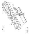
- FIG. 5 is an exploded perspective view of a selector positioned for assembly into a housing of a trigger system and constructed in accordance with the principles of the present invention
- FIG. 6A is a top view of a selector resiliently biased to a neutral position within a housing of a trigger system and constructed in accordance with the principles of the present invention
- FIG. 6B is an exterior perspective view of a selector disposed within a housing of a trigger system and constructed in accordance with the principles of the present invention
- FIG. 7 is a perspective view of a trigger system disposed within a second half of a plasma arc torch handle, with a selector in a neutral position, and constructed in accordance with the principles of the present invention
- FIG. 8 is a perspective view of a selector within a trigger system positioned in a first operating position and constructed in accordance with the principles of the present invention
- FIG. 9 is a perspective view of a selector positioned in a second operating position and constructed in accordance with the principles of the present invention.
- FIG. 10 is a cross-sectional view of an alternate embodiment of a trigger system, wherein a selector activates gas and electric power in accordance with the teachings of the present invention.
- a trigger system is generally operable with a manually operated plasma arc apparatus as indicated by reference numeral 10 in FIG. 1 .
- the manually operated plasma arc apparatus 10 comprises a plasma arc torch 12 connected to a power supply 14 through a torch lead 16 , which may be available in a variety of lengths according to a specific application.
- the power supply 14 provides both gas and electric power, which flow through the torch lead 16 , for operation of the plasma arc torch 12 as described in greater detail below.
- the trigger system 20 comprises a housing 22 disposed within a torch handle 24 of the plasma arc torch 12 , and a selector 26 disposed within the housing 22 .
- the selector 26 is operable between at least one of a first operating position, a second operating position, and preferably a neutral position, which are described in further detail below.
- the selector 26 operates the plasma arc apparatus 10 (not shown) in a first mode to deliver gas to the plasma arc torch 12 .
- the selector 26 operates the plasma arc apparatus 10 in a second mode to deliver gas and electric power to the plasma arc torch 12 .
- the selector 26 when the selector 26 is in the neutral position, delivery of gas and electric power to the plasma arc torch 12 is inhibited. Accordingly, an operator may select the first mode to provide gas only for operations such as cooling torch components, or the operator may select the second mode to provide gas and electric power for operations such as cutting workpieces.
- FIG. 3A illustrates the first operating position of the selector 26 that causes the plasma arc apparatus 10 (not shown) to operate in a first mode to deliver gas to the plasma arc torch 12 .
- the selector 26 is preferably slidably operable along the housing 22 in the direction of arrow A such that a post 28 of the selector 26 clears a stop 30 defined within the torch handle 24 .
- the housing 22 is then pivoted in the direction of arrow B about axis X such that the housing 22 activates a gas control device 32 to initiate gas flow from the power supply 14 (not shown) to the plasma arc torch 12 .
- the first mode supplies gas only to the plasma arc torch 12 .
- FIG. 3B illustrates the second operating position of the selector 26 that causes the plasma arc apparatus 10 to operate in a second mode to deliver gas and electric power to the plasma arc torch 12 .
- the selector 26 is slidably operable along the housing 22 in the direction of arrow C such that the post 28 again clears the stop 30 .
- the housing 22 is then pivoted in the direction of arrow B about axis X while the selector 26 continues to be slidably operated along the housing 22 in the direction of arrow C.
- an engagement member 34 of the selector 26 activates a power switch 36 disposed within the torch handle 24 , which activates the supply of electric power from the power supply 14 to the plasma arc torch 12 .
- the housing 22 activates the gas control device 32 as previously described to initiate gas flow from the power supply 14 to the plasma arc torch 12 . Accordingly, the plasma arc torch 12 is operated in the second mode with the supply of both gas and electric power.
- the gas control device 32 may be omitted from the plasma arc torch 12 such that gas flow is activated by a gas control device within the power supply 14 .
- the gas control device may be controlled by the power switch 36 or by an alternate switch (not shown) that may be activated by either the selector 26 or the housing 22 in the second operating position of the selector 26 .
- a second stop 31 is positioned within the torch handle 24 as shown. Accordingly, if an operator attempts to move the selector 26 forward in the direction of arrow A, the second stop 31 prevents such movement.
- the second stop 31 may simply be removed to allow for motion of the selector 26 in the direction of arrow A to activate the gas control device 32 .
- the neutral position of the selector 26 is illustrated, which causes the plasma arc apparatus 10 to operate in a neutral mode to inhibit the supply of gas and electric power to the plasma arc torch 12 .
- the selector 26 is resiliently biased to the neutral position from first and second operating positions.
- the post 28 of the selector 26 is engaged with an adjacent member within the plasma arc torch, preferably the stop 30 within the torch handle 24 , such that upward movement of the selector 26 and pivoting of the housing 22 in the direction of arrow B is limited, thereby inhibiting the delivery of gas and electric power to the plasma arc torch 12 .
- the selector 26 In order to pivot the housing 22 for operation of the plasma arc torch 12 in either the first or second mode, therefore, the selector 26 must be moved to either the first operating position or the second operating, respectively.
- the selector 26 is preferably biased to the neutral position with a first spring 38 and a second spring 39 disposed within the housing 22 .
- both the first spring 38 and the second spring 39 are partially compressed when the selector 26 is in the neutral position.
- the first spring 38 compresses further, and compression of the second spring 39 is reduced as shown in FIG. 3A .
- the second spring 39 compresses further, and compression of the first spring 38 is reduced as shown in FIG. 3B .
- the first spring 38 and the second spring 39 resiliently bias the selector 26 to the neutral position.
- the torch handle 24 comprises a first handle half 44 and a second handle half 46 , in which the trigger system 40 according to the present invention is disposed.
- the housing 22 of the trigger system 40 comprises two pins 48 and 50 that engage a pin bearing cup 52 on the second handle half 46 and a pin bearing cup 54 (shown dashed) on the first handle half 44 .
- the housing 22 comprises a first retention tab 56 that engages portions 58 of the handle halves 44 and 46 at a distal end of the housing 22 .
- the housing 22 comprises second and third retention tabs 60 and 62 that engage portions 64 of the handle halves 44 and 46 at a proximal end of the housing 22 . Accordingly, the retention tabs 56 , 60 , and 62 retain the housing 22 within the assembled handle halves 44 and 46 , while the pins 48 and 50 allow the housing 22 to pivot during operation as described in greater detail below.
- proximal or proximal direction should be construed as meaning towards or in the direction of the power supply 14 (not shown), and the terms distal or distal direction should be construed as meaning towards or in the direction of a torch head 76 .
- the gas control device 32 is also disposed within the torch handle 24 and is positioned and retained by mating brackets 68 located within the handle halves 44 and 46 . Accordingly, the brackets 68 secure the gas control device 32 within the torch handle 24 and properly position the gas control device 32 for activation by the housing 22 , as described in greater detail below, to activate the supply of gas to the plasma arc torch 12 .
- the power switch 36 is disposed within the second handle half 46 , preferably using one or more switch pins 72 that mate with one or more apertures 74 provided in the power switch 36 . Accordingly, the switch pins 72 properly position the power switch 36 for activation by the selector 26 , as described in greater detail below, to activate the supply of electric power to the plasma arc torch 12 .
- the torch head 76 is also disposed within the plasma arc torch 12 and is positioned by shoulders 78 on the handle halves 44 and 46 .
- both gas and electric power are provided to the torch head 76 through operation of the trigger system 40 according to the present invention such that a plasma stream is generated and plasma is ejected from a tip 80 for operations such as cutting, marking, gouging, or spraying, among others.
- the first handle half 44 is placed adjacent the second handle half 46 and is secured thereto, preferably using a plurality of mechanical fasteners (not shown) through fastening holes 82 .
- the handle halves may be connected using a quick disconnect as disclosed in copending application titled “Modular Plasma Arc Torch,” filed Feb. 26, 2002, which is commonly assigned with the present application and the contents of which are incorporated herein by reference.
- the torch handle 24 provides thermal and electric isolation between the components disposed therein and an operator holding the plasma arc torch 12 .
- a nonconductive material such as Nylon is used for the material of the first handle half 64 and the second handle half 66 .
- the retention members e.g. first ledges 58 , second ledges 64 , brackets 68 , located within the first handle half 46 and the second handle half 48 are preferably integrally molded with the torch handle 24 , although separate members may be mounted therein in accordance with the teachings of the present invention.
- the housing 22 and the selector 26 of the trigger system 40 are described in further detail.
- the selector 26 is assembled into the housing 22 by inserting the selector 26 in the direction of arrow D into an aperture 84 defined by the housing 22 .
- the selector 26 is then translated in the direction of arrow E until the engagement member 34 of the selector 26 is properly positioned within the housing 22 .
- a housing first spring boss 90 is formed within a distal portion of the housing 22 and a selector first spring boss 92 is formed within a distal portion of the selector 26 to position and retain the first spring 38 .
- a housing second spring boss 94 is formed within a proximal portion of the housing 22 and a selector second spring post 96 (shown dashed) is formed within a proximal portion of the selector 26 to position and retain the second spring 39 .
- an engagement cup 98 is defined within the housing 22 for operation of the gas control device 32 (not shown) as described in greater detail below.
- the housing 22 also defines slide retainers 100 , which provide a boundary for the selector 26 to maintain proper orientation thereof during operation.
- the exterior of the trigger system 40 is illustrated, wherein the selector 26 preferably defines raised ribs 102 to facilitate an improved grip between the hands or gloves of an operator and the selector 26 , which further aids in positioning the selector 26 . Additionally, the selector 26 is preferably disposed between parallel guides 104 to prevent rotation or misalignment of the selector 26 during operation.
- the trigger system 40 fully assembled within an exemplary embodiment of the present invention is illustrated in further detail.
- the post 28 of the selector 26 is in slideable contact with the stop 30 of the torch handle 24 such that the housing 22 is inhibited from pivoting about axis F, which is formed along a common centerline of the pins 48 and 50 of the housing 22 .
- the first spring 38 and the second spring 39 resiliently bias the selector 26 as shown.
- Such a position of the selector 26 is defined as the neutral position of the trigger system 40 , wherein the neutral mode is selected. Accordingly, the housing is prevented from pivoting, and thus the gas control device 32 and the power switch 36 cannot be actuated. As a result, the supply of gas and electric power, respectively, to the plasma arc torch 12 is inhibited in the neutral mode.
- the trigger system 40 is shown with the selector 26 in the first operating position, in which only gas is provided to the plasma arc torch 12 in the first operating mode.
- the operator moves the selector 26 in the direction of arrow G until the post 28 is disengaged from, or clears, the stop 30 as shown. Accordingly, the first spring 38 is further compressed, and compression of the second spring 39 is reduced.
- the housing 22 may be pivoted about axis F in the direction of arrow H. Accordingly, the engagement cup 98 engages the gas control device 32 to activate gas flow to the plasma arc torch 12 .
- the trigger system 40 is shown with the selector 26 in the second operating position, in which gas and electric power are provided to the plasma arc torch 12 in the second operating mode.
- the operator moves the selector 26 in the direction of arrow I until the post 28 disengages from, or clears, the stop 30 as shown. Accordingly, the second spring 39 is further compressed, compression of the first spring 38 is reduced.
- the housing 22 may be pivoted about axis F in the direction of arrow J, while the selector 26 continues to be moved in the direction of arrow I.
- the engagement cup 98 activates the gas control device 32 to activate gas flow to the plasma arc torch 12 and the engagement member 34 of the selector 26 activates the power switch 36 to initiate electric power to the plasma arc torch 12 .
- the combination of translating the selector 26 in the direction of arrow I and pivoting of the housing 22 about axis F provides the requisite physical contact between the engagement cup 98 and the gas control device 32 and between the engagement member 34 and the power switch 36 to activate both gas and electric power to the plasma arc torch 12 .
- the trigger system 40 in another form may be configured such that the selector 26 activates the gas control device 32 rather than the housing 22 as previously described.
- the selector 26 further comprises an extension 120 that activates the gas control device 32 to activate the supply of working gas to the plasma arc torch 12 .
- the gas control device 32 may be one of many possible devices such as a gas control valve, a switch that activates a gas control device (e.g., solenoid) in a power supply, or a solenoid, among others.
- Gas control within the handle 28 is further described in copending application titled “Torch Handle Gas Control,” filed Feb. 26, 2002, which is commonly assigned with the present application and the contents of which are incorporated by reference.
- the trigger system 40 of the present invention provides multiple operating modes for a plasma arc apparatus. Namely, at least a first operating mode is provided such that gas only is provided for operations such as cooling torch components or workpieces, along with a second operating mode such that gas and electric power are provided for operation of the plasma arc torch, and preferably a neutral mode is provided such that the supply of gas and electric power to the plasma arc torch inhibited.
- a first operating mode is provided such that gas only is provided for operations such as cooling torch components or workpieces
- a second operating mode such that gas and electric power are provided for operation of the plasma arc torch
- a neutral mode is provided such that the supply of gas and electric power to the plasma arc torch inhibited.
- the power switch 36 as shown is preferably a microswitch having a switch depressible arm to make or break electrical contact and to allow or prevent the flow of electric power, or current, although a variety of electrical switches may be employed without departing from the spirit and scope of the invention.
- the selector 26 may be resiliently biased to the neutral position by alternate methods other than the first and second spring such as positioning slots within, for example, the housing 22 . Additionally, the housing 22 and the selector 26 may follow other motions rather than the pivoting and sliding as described herein to activate the gas control device and the power switch. Accordingly, such variations are not to be regarded as a departure from the spirit and scope of the invention.
Landscapes
- Physics & Mathematics (AREA)
- Engineering & Computer Science (AREA)
- Plasma & Fusion (AREA)
- Spectroscopy & Molecular Physics (AREA)
- Plasma Technology (AREA)
Abstract
Description
Claims (50)
Priority Applications (1)
| Application Number | Priority Date | Filing Date | Title |
|---|---|---|---|
| US10/674,915 US7022936B2 (en) | 2002-02-26 | 2003-09-30 | Plasma arc torch trigger system |
Applications Claiming Priority (2)
| Application Number | Priority Date | Filing Date | Title |
|---|---|---|---|
| US10/083,219 US6700091B2 (en) | 2002-02-26 | 2002-02-26 | Plasma arc torch trigger system |
| US10/674,915 US7022936B2 (en) | 2002-02-26 | 2003-09-30 | Plasma arc torch trigger system |
Related Parent Applications (1)
| Application Number | Title | Priority Date | Filing Date |
|---|---|---|---|
| US10/083,219 Continuation US6700091B2 (en) | 2002-02-26 | 2002-02-26 | Plasma arc torch trigger system |
Publications (2)
| Publication Number | Publication Date |
|---|---|
| US20050098544A1 US20050098544A1 (en) | 2005-05-12 |
| US7022936B2 true US7022936B2 (en) | 2006-04-04 |
Family
ID=27753254
Family Applications (2)
| Application Number | Title | Priority Date | Filing Date |
|---|---|---|---|
| US10/083,219 Expired - Lifetime US6700091B2 (en) | 2002-02-26 | 2002-02-26 | Plasma arc torch trigger system |
| US10/674,915 Expired - Lifetime US7022936B2 (en) | 2002-02-26 | 2003-09-30 | Plasma arc torch trigger system |
Family Applications Before (1)
| Application Number | Title | Priority Date | Filing Date |
|---|---|---|---|
| US10/083,219 Expired - Lifetime US6700091B2 (en) | 2002-02-26 | 2002-02-26 | Plasma arc torch trigger system |
Country Status (3)
| Country | Link |
|---|---|
| US (2) | US6700091B2 (en) |
| AU (1) | AU2003213288A1 (en) |
| WO (1) | WO2003073802A2 (en) |
Cited By (1)
| Publication number | Priority date | Publication date | Assignee | Title |
|---|---|---|---|---|
| USD914071S1 (en) | 2018-11-02 | 2021-03-23 | Esab Ab | Welding device enclosure |
Families Citing this family (26)
| Publication number | Priority date | Publication date | Assignee | Title |
|---|---|---|---|---|
| US6992262B2 (en) * | 2003-10-09 | 2006-01-31 | Illinois Tool Works Inc. | Method and apparatus for localized control of a plasma cutter |
| US7022935B1 (en) * | 2003-12-08 | 2006-04-04 | Illinois Tool Works Inc. | Plasma-cutting torch with integrated high frequency starter |
| US7372623B2 (en) * | 2005-03-29 | 2008-05-13 | Asml Netherlands B.V. | Multi-layer spectral purity filter, lithographic apparatus including such a spectral purity filter, device manufacturing method, and device manufactured thereby |
| US7232970B1 (en) * | 2005-06-03 | 2007-06-19 | Li-Hsueh Chen | Safety start switch for a pneumatic tool |
| US7989727B2 (en) * | 2006-09-13 | 2011-08-02 | Hypertherm, Inc. | High visibility plasma arc torch |
| US9662747B2 (en) | 2006-09-13 | 2017-05-30 | Hypertherm, Inc. | Composite consumables for a plasma arc torch |
| US10098217B2 (en) | 2012-07-19 | 2018-10-09 | Hypertherm, Inc. | Composite consumables for a plasma arc torch |
| US9560732B2 (en) | 2006-09-13 | 2017-01-31 | Hypertherm, Inc. | High access consumables for a plasma arc cutting system |
| US10194516B2 (en) | 2006-09-13 | 2019-01-29 | Hypertherm, Inc. | High access consumables for a plasma arc cutting system |
| US8952294B2 (en) * | 2007-05-21 | 2015-02-10 | Illinois Tool Works Inc. | Welding torch handle utilizing slot for trigger attachment |
| US9186743B2 (en) * | 2009-11-16 | 2015-11-17 | Illinois Tool Works Inc. | Welding and gouging systems with multiple power settings |
| JP5471573B2 (en) * | 2010-02-19 | 2014-04-16 | 日立工機株式会社 | Electric tool |
| EP2521228B1 (en) | 2011-05-05 | 2014-01-01 | ABB Research Ltd. | Device and method for quick closing of an electric circuit and a use of the device |
| US8772668B2 (en) * | 2011-08-19 | 2014-07-08 | Illinois Tool Works Inc. | Plasma torch and torch handle having ergonomic features |
| US8640345B2 (en) * | 2011-09-30 | 2014-02-04 | Robert Bosch Gmbh | Lockout forward flip lever for power saw |
| US8872049B2 (en) | 2012-04-18 | 2014-10-28 | Milwaukee Electric Tool Corporation | Trigger lock-on lock-off mechanism |
| ITVI20130219A1 (en) * | 2013-09-05 | 2015-03-06 | Trafimet Spa | WELDING OR PLASMA TORCH AND DEVICE THAT USES SUCH TORCH. |
| US9737953B2 (en) * | 2014-02-24 | 2017-08-22 | Lincoln Global, Inc. | Manual plasma system with remote control |
| BR102014021846A2 (en) * | 2014-09-03 | 2015-12-01 | Powermig Automação E Soldagem Ltda | plasma torch control and identification circuit |
| US9833860B1 (en) | 2016-07-22 | 2017-12-05 | Lincoln Global, Inc. | System and method for plasma arc transfer for plasma cutting |
| WO2018076007A1 (en) * | 2016-10-21 | 2018-04-26 | Hypertherm, Inc. | Plasma power tool |
| WO2018132682A1 (en) | 2017-01-13 | 2018-07-19 | Hypertherm, Inc. | Disabling plasma arc torches and related systems and methods |
| EP3606293B1 (en) * | 2017-03-31 | 2022-09-07 | Fuji Corporation | Plasma generation device |
| EP3943749A1 (en) | 2017-04-28 | 2022-01-26 | Graco Minnesota Inc. | Portable hydraulic power unit |
| USD968490S1 (en) * | 2019-08-06 | 2022-11-01 | Tec.Mo. S.R.L. | Trigger handle for a plasma torch |
| USD904318S1 (en) | 2019-12-13 | 2020-12-08 | Graco Minnesota Inc. | Control pendant |
Citations (6)
| Publication number | Priority date | Publication date | Assignee | Title |
|---|---|---|---|---|
| US3581051A (en) * | 1967-08-01 | 1971-05-25 | Nat Res Dev | Welding apparatus |
| US3662147A (en) * | 1970-03-26 | 1972-05-09 | Ogden Eng Corp | Welding gun trigger control circuit |
| US5039837A (en) * | 1990-02-23 | 1991-08-13 | Tescom Corporation | Plasma torch head, body, handle and control circuitry |
| US5357076A (en) | 1991-04-12 | 1994-10-18 | The Lincoln Electric Company | Plasma torch with identification circuit |
| US5597497A (en) * | 1994-12-20 | 1997-01-28 | Hypertherm, Inc. | Switch mechanism for operating a plasma arc torch, other tools or weapons |
| US5698122A (en) * | 1995-12-05 | 1997-12-16 | The Miller Group Ltd. | Dual switch for semi automatic welding gun |
Family Cites Families (8)
| Publication number | Priority date | Publication date | Assignee | Title |
|---|---|---|---|---|
| US3469070A (en) | 1967-06-29 | 1969-09-23 | Arthur A Bernard | Arc welding gun |
| US3629547A (en) | 1970-02-09 | 1971-12-21 | Tweco Prod Inc | Semiautomatic welding apparatus |
| US3873796A (en) | 1973-07-06 | 1975-03-25 | Black & Decker Mfg Co | Trigger mechanism for hand-operated power device including independently operable locking devices providing automatic lock off and manual lock-on operation |
| US4250366A (en) | 1979-03-30 | 1981-02-10 | Dover Corporation | Trigger assembly for arc welding gun |
| US4554432A (en) | 1984-10-05 | 1985-11-19 | Dover Corporation | Components for gas metal arc welding gun |
| US4731518A (en) | 1986-12-12 | 1988-03-15 | The Lincoln Electric Company | Gun and cable for gas metal arc welding |
| US5338917A (en) | 1992-02-26 | 1994-08-16 | Tweco Products, Inc. | Ergonomic welding gun with quick disconnect cable assembly |
| US6025574A (en) | 1998-08-07 | 2000-02-15 | Illinois Tool Works Inc | Trigger locking pin mechanism for mig gun |
-
2002
- 2002-02-26 US US10/083,219 patent/US6700091B2/en not_active Expired - Lifetime
-
2003
- 2003-02-25 AU AU2003213288A patent/AU2003213288A1/en not_active Abandoned
- 2003-02-25 WO PCT/US2003/005763 patent/WO2003073802A2/en not_active Application Discontinuation
- 2003-09-30 US US10/674,915 patent/US7022936B2/en not_active Expired - Lifetime
Patent Citations (6)
| Publication number | Priority date | Publication date | Assignee | Title |
|---|---|---|---|---|
| US3581051A (en) * | 1967-08-01 | 1971-05-25 | Nat Res Dev | Welding apparatus |
| US3662147A (en) * | 1970-03-26 | 1972-05-09 | Ogden Eng Corp | Welding gun trigger control circuit |
| US5039837A (en) * | 1990-02-23 | 1991-08-13 | Tescom Corporation | Plasma torch head, body, handle and control circuitry |
| US5357076A (en) | 1991-04-12 | 1994-10-18 | The Lincoln Electric Company | Plasma torch with identification circuit |
| US5597497A (en) * | 1994-12-20 | 1997-01-28 | Hypertherm, Inc. | Switch mechanism for operating a plasma arc torch, other tools or weapons |
| US5698122A (en) * | 1995-12-05 | 1997-12-16 | The Miller Group Ltd. | Dual switch for semi automatic welding gun |
Cited By (1)
| Publication number | Priority date | Publication date | Assignee | Title |
|---|---|---|---|---|
| USD914071S1 (en) | 2018-11-02 | 2021-03-23 | Esab Ab | Welding device enclosure |
Also Published As
| Publication number | Publication date |
|---|---|
| US20050098544A1 (en) | 2005-05-12 |
| AU2003213288A1 (en) | 2003-09-09 |
| US20030160031A1 (en) | 2003-08-28 |
| WO2003073802A2 (en) | 2003-09-04 |
| AU2003213288A8 (en) | 2003-09-09 |
| US6700091B2 (en) | 2004-03-02 |
| WO2003073802A3 (en) | 2003-11-27 |
Similar Documents
| Publication | Publication Date | Title |
|---|---|---|
| US7022936B2 (en) | Plasma arc torch trigger system | |
| US5597497A (en) | Switch mechanism for operating a plasma arc torch, other tools or weapons | |
| EP1487604B1 (en) | Start cartridge ; plasma arc torch with such cartridge and method of initiating a pilot arc torch by using such cartridge | |
| US9486874B2 (en) | Control assembly for a welding gun | |
| US6979799B2 (en) | System and method for operating and locking a trigger of a welding gun | |
| EP2011375B1 (en) | High visibility plasma arc torch | |
| EP1676665B1 (en) | System of conserving plasma torch consumable | |
| US4967055A (en) | Plasma torch | |
| US7582844B2 (en) | Torch handle gas control | |
| EP1676666A2 (en) | Method and system of conserving plasma torch consumable | |
| JP2001502110A (en) | Plasma arc torch and method using contact starting system | |
| US6096993A (en) | Safety device for a plasma torch | |
| JP2004074278A (en) | Welding gun having contact tip and method for operating the same | |
| EP2745653B1 (en) | Plasma torch and torch handle having ergonomic features | |
| JP2004525770A (en) | Strain release mechanism for plasma arc torch | |
| CN107639329B (en) | System and method for plasma arc transfer for plasma cutting | |
| US20150163892A1 (en) | Method and apparatus for recycling shield gas in a plasma arc torch | |
| EP1631129A2 (en) | Multi-position head plasma torch | |
| WO1996039255A1 (en) | Safety apparatus for high pressure liquid jet system | |
| KR102030579B1 (en) | torch apparatus for tig welding | |
| JP2005329434A (en) | Electrode for plasma torch | |
| JP3220616B2 (en) | Plasma arc transfer type cutting device | |
| US20050155964A1 (en) | Woodburning device | |
| KR20190090135A (en) | Soldering Iron |
Legal Events
| Date | Code | Title | Description |
|---|---|---|---|
| AS | Assignment |
Owner name: THERMAL DYNAMICS CORPORATION, NEW HAMPSHIRE Free format text: ASSIGNMENT OF ASSIGNORS INTEREST;ASSIGNORS:JONES, JOSEPH P.;HORNER-RICHARDSON, KEVIN D.;KINERSON, KEVIN J.;REEL/FRAME:016841/0386 Effective date: 20020226 |
|
| STCF | Information on status: patent grant |
Free format text: PATENTED CASE |
|
| AS | Assignment |
Owner name: GENERAL ELECTRIC CAPITAL CORPORATION, AS AGENT, CO Free format text: SECURITY AGREEMENT;ASSIGNOR:THERMAL DYNAMICS CORPORATION;REEL/FRAME:023094/0514 Effective date: 20090814 Owner name: GENERAL ELECTRIC CAPITAL CORPORATION, AS AGENT,CON Free format text: SECURITY AGREEMENT;ASSIGNOR:THERMAL DYNAMICS CORPORATION;REEL/FRAME:023094/0514 Effective date: 20090814 |
|
| AS | Assignment |
Owner name: REGIONS BANK, GEORGIA Free format text: PATENT SECURITY AGREEMENT;ASSIGNOR:THERMAL DYNAMICS CORPORATION;REEL/FRAME:023163/0056 Effective date: 20090814 Owner name: REGIONS BANK,GEORGIA Free format text: PATENT SECURITY AGREEMENT;ASSIGNOR:THERMAL DYNAMICS CORPORATION;REEL/FRAME:023163/0056 Effective date: 20090814 |
|
| FPAY | Fee payment |
Year of fee payment: 4 |
|
| AS | Assignment |
Owner name: U.S. BANK NATIONAL ASSOCIATION, AS COLLATERAL TRUS Free format text: SECURITY AGREEMENT;ASSIGNOR:THERMAL DYNAMICS CORPORATION;REEL/FRAME:025441/0313 Effective date: 20101203 |
|
| AS | Assignment |
Owner name: GENERAL ELECTRIC CAPITAL CORPORATION, AS AGENT, CO Free format text: SECURITY AGREEMENT;ASSIGNOR:THERMAL DYNAMICS CORPORATION;REEL/FRAME:025451/0613 Effective date: 20101203 |
|
| FPAY | Fee payment |
Year of fee payment: 8 |
|
| AS | Assignment |
Owner name: VICTOR TECHNOLOGIES GROUP, INC., MISSOURI Free format text: RELEASE OF SECURITY INTEREST;ASSIGNOR:U.S BANK, NATIONAL ASSOCIATION;REEL/FRAME:033370/0775 Effective date: 20140414 |
|
| AS | Assignment |
Owner name: VICTOR EQUIPMENT COMPANY, NEW JERSEY Free format text: RELEASE OF SECURITY INTEREST;ASSIGNOR:GENERAL ELECTRIC CAPITAL CORPORATION;REEL/FRAME:033421/0785 Effective date: 20140414 Owner name: THERMAL DYNAMICS CORPORATION, MISSOURI Free format text: RELEASE OF SECURITY INTEREST;ASSIGNOR:GENERAL ELECTRIC CAPITAL CORPORATION;REEL/FRAME:033421/0785 Effective date: 20140414 Owner name: STOODY COMPANY, MISSOURI Free format text: RELEASE OF SECURITY INTEREST;ASSIGNOR:GENERAL ELECTRIC CAPITAL CORPORATION;REEL/FRAME:033421/0785 Effective date: 20140414 |
|
| AS | Assignment |
Owner name: TWECO PRODUCTS, INC., MISSOURI Free format text: LIEN;ASSIGNOR:REGIONS BANK;REEL/FRAME:033646/0880 Effective date: 20100630 |
|
| AS | Assignment |
Owner name: DEUTSCHE BANK AG NEW YORK BRANCH, NEW YORK Free format text: SECURITY INTEREST;ASSIGNORS:VICTOR TECHNOLOGIES INTERNATIONAL INC.;VICTOR EQUIPMENT COMPANY;THERMAL DYNAMICS CORPORATION;AND OTHERS;REEL/FRAME:033831/0404 Effective date: 20140813 |
|
| AS | Assignment |
Owner name: DISTRIBUTION MINING & EQUIPMENT COMPANY, LLC, DELAWARE Free format text: RELEASE BY SECURED PARTY;ASSIGNOR:DEUTSCHE BANK AG NEW YORK BRANCH;REEL/FRAME:035903/0051 Effective date: 20150605 Owner name: CONSTELLATION PUMPS CORPORATION, DELAWARE Free format text: RELEASE BY SECURED PARTY;ASSIGNOR:DEUTSCHE BANK AG NEW YORK BRANCH;REEL/FRAME:035903/0051 Effective date: 20150605 Owner name: ANDERSON GROUP INC., SOUTH CAROLINA Free format text: RELEASE BY SECURED PARTY;ASSIGNOR:DEUTSCHE BANK AG NEW YORK BRANCH;REEL/FRAME:035903/0051 Effective date: 20150605 Owner name: EMSA HOLDINGS INC., SOUTH CAROLINA Free format text: RELEASE BY SECURED PARTY;ASSIGNOR:DEUTSCHE BANK AG NEW YORK BRANCH;REEL/FRAME:035903/0051 Effective date: 20150605 Owner name: HOWDEN GROUP LIMITED, SCOTLAND Free format text: RELEASE BY SECURED PARTY;ASSIGNOR:DEUTSCHE BANK AG NEW YORK BRANCH;REEL/FRAME:035903/0051 Effective date: 20150605 Owner name: HOWDEN AMERICAN FAN COMPANY, SOUTH CAROLINA Free format text: RELEASE BY SECURED PARTY;ASSIGNOR:DEUTSCHE BANK AG NEW YORK BRANCH;REEL/FRAME:035903/0051 Effective date: 20150605 Owner name: STOODY COMPANY, MISSOURI Free format text: RELEASE BY SECURED PARTY;ASSIGNOR:DEUTSCHE BANK AG NEW YORK BRANCH;REEL/FRAME:035903/0051 Effective date: 20150605 Owner name: COLFAX CORPORATION, MARYLAND Free format text: RELEASE BY SECURED PARTY;ASSIGNOR:DEUTSCHE BANK AG NEW YORK BRANCH;REEL/FRAME:035903/0051 Effective date: 20150605 Owner name: HOWDEN COMPRESSORS, INC., SOUTH CAROLINA Free format text: RELEASE BY SECURED PARTY;ASSIGNOR:DEUTSCHE BANK AG NEW YORK BRANCH;REEL/FRAME:035903/0051 Effective date: 20150605 Owner name: VICTOR EQUIPMENT COMPANY, MISSOURI Free format text: RELEASE BY SECURED PARTY;ASSIGNOR:DEUTSCHE BANK AG NEW YORK BRANCH;REEL/FRAME:035903/0051 Effective date: 20150605 Owner name: IMO INDUSTRIES INC., DELAWARE Free format text: RELEASE BY SECURED PARTY;ASSIGNOR:DEUTSCHE BANK AG NEW YORK BRANCH;REEL/FRAME:035903/0051 Effective date: 20150605 Owner name: CLARUS FLUID INTELLIGENCE, LLC, WASHINGTON Free format text: RELEASE BY SECURED PARTY;ASSIGNOR:DEUTSCHE BANK AG NEW YORK BRANCH;REEL/FRAME:035903/0051 Effective date: 20150605 Owner name: DISTRIBUTION MINING & EQUIPMENT COMPANY, LLC, DELA Free format text: RELEASE BY SECURED PARTY;ASSIGNOR:DEUTSCHE BANK AG NEW YORK BRANCH;REEL/FRAME:035903/0051 Effective date: 20150605 Owner name: THE ESAB GROUP INC., SOUTH CAROLINA Free format text: RELEASE BY SECURED PARTY;ASSIGNOR:DEUTSCHE BANK AG NEW YORK BRANCH;REEL/FRAME:035903/0051 Effective date: 20150605 Owner name: SHAWEBONE HOLDINGS INC., SOUTH CAROLINA Free format text: RELEASE BY SECURED PARTY;ASSIGNOR:DEUTSCHE BANK AG NEW YORK BRANCH;REEL/FRAME:035903/0051 Effective date: 20150605 Owner name: ALLOY RODS GLOBAL INC., DELAWARE Free format text: RELEASE BY SECURED PARTY;ASSIGNOR:DEUTSCHE BANK AG NEW YORK BRANCH;REEL/FRAME:035903/0051 Effective date: 20150605 Owner name: ESAB AB, SWEDEN Free format text: RELEASE BY SECURED PARTY;ASSIGNOR:DEUTSCHE BANK AG NEW YORK BRANCH;REEL/FRAME:035903/0051 Effective date: 20150605 Owner name: VICTOR TECHNOLOGIES INTERNATIONAL, INC., MISSOURI Free format text: RELEASE BY SECURED PARTY;ASSIGNOR:DEUTSCHE BANK AG NEW YORK BRANCH;REEL/FRAME:035903/0051 Effective date: 20150605 Owner name: HOWDEN NORTH AMERICA INC., SOUTH CAROLINA Free format text: RELEASE BY SECURED PARTY;ASSIGNOR:DEUTSCHE BANK AG NEW YORK BRANCH;REEL/FRAME:035903/0051 Effective date: 20150605 Owner name: TOTAL LUBRICATION MANAGEMENT COMPANY, TEXAS Free format text: RELEASE BY SECURED PARTY;ASSIGNOR:DEUTSCHE BANK AG NEW YORK BRANCH;REEL/FRAME:035903/0051 Effective date: 20150605 Owner name: ALCOTEC WIRE CORPORATION, MICHIGAN Free format text: RELEASE BY SECURED PARTY;ASSIGNOR:DEUTSCHE BANK AG NEW YORK BRANCH;REEL/FRAME:035903/0051 Effective date: 20150605 |
|
| AS | Assignment |
Owner name: VICTOR EQUIPMENT COMPANY, MISSOURI Free format text: MERGER;ASSIGNOR:THERMAL DYNAMICS CORPORATION;REEL/FRAME:037711/0952 Effective date: 20141219 |
|
| MAFP | Maintenance fee payment |
Free format text: PAYMENT OF MAINTENANCE FEE, 12TH YEAR, LARGE ENTITY (ORIGINAL EVENT CODE: M1553) Year of fee payment: 12 |