US700960A - Loading attachment for hand-trucks. - Google Patents
Loading attachment for hand-trucks. Download PDFInfo
- Publication number
- US700960A US700960A US8665501A US1901086655A US700960A US 700960 A US700960 A US 700960A US 8665501 A US8665501 A US 8665501A US 1901086655 A US1901086655 A US 1901086655A US 700960 A US700960 A US 700960A
- Authority
- US
- United States
- Prior art keywords
- truck
- lever
- hand
- trucks
- box
- Prior art date
- Legal status (The legal status is an assumption and is not a legal conclusion. Google has not performed a legal analysis and makes no representation as to the accuracy of the status listed.)
- Expired - Lifetime
Links
Images
Classifications
-
- B—PERFORMING OPERATIONS; TRANSPORTING
- B62—LAND VEHICLES FOR TRAVELLING OTHERWISE THAN ON RAILS
- B62B—HAND-PROPELLED VEHICLES, e.g. HAND CARTS OR PERAMBULATORS; SLEDGES
- B62B1/00—Hand carts having only one axis carrying one or more transport wheels; Equipment therefor
- B62B1/10—Hand carts having only one axis carrying one or more transport wheels; Equipment therefor in which the load is intended to be transferred totally to the wheels
Definitions
- This invention relates to an improved attachment for hand-trucks designed to facilitate the operation of loading boxes and the like thereon.
- the invention embraces generally the application to the lower part of a hand-truck of an auxiliary foot-lever which extends rearwardly from the hand-truck in such position that the f oot of the person using the truck may engage the same, said lever being adapted to engage at its forward end a part of the truck in such manner that when downward pressure is applied to the rear end of the lever, which is designed to occur when the truck is being tilted rearwardly in loading a box thereon, said auxiliary lever will exert power to assist the tilting of the truck and raising the box or case thereon.
- My invention is capable of being attached to a truck already in use and may also be made a part of the truck in its original construction.
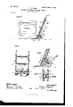
- Figure l is a vertical section of a hand-truck provided with my improved attachment, showing such truck with the nose thereof under a box or case preparatory to loading said box on the truck.
- Fig. 2 is a rearview of a truck and the attachment.
- Fig. 3 is an enlarged vertical section of the lower part of the tru ok, showing my improved attachment in position for exerting lifting power on the lower end of the truck.
- Fig. 4. is a horizontal section taken on line 4 4. of Fig. 8.
- A designates as a whole a hand-truck of common form
- Said truck is provided with the usual nose A', adapted to be inserted beneath the box or case in the manner shown in Fig. 1 preparatory to loading said box or case thereon.
- B designates a lever'which is located in rear of the lower part of the truck and is pivoted near its lower end upon a transverse pivot-pin O, extending through laterally-separated lugs c, projecting rearwardly from a bearing-bracket C, ⁇ attached to the rear face of the lowermost cross-bar a of the truck, said lever being provided with a lug b, which is located between and has overlapping engagement with the lugs c of the bracket C.
- the forward end of said lever B projects beneath the lower cross-bar of the truck-frame and is provided with a short upturned portion b', adapted for engagement with the under surface of said lowermost cross-bar or preferably and as herein shown with a metal wearing-plate 0.5, attached to the under side of said bar.
- the lever Bis adapted to bearat its lower side against the upper side of the axle d3, on which the supportingwheels are mounted, and in order to permit accurate engagement of the lever with said cross-bar orwearing-plate the lever is adapted to fit somewhat loosely on its pivot-pin.
- Said lever is ⁇ formed atits rear end to provide a flat footpiece 222,"adapted to be engaged by the foot of the person using the truck to depress said lever.
- the lever is provided in its part engaging the shaft a3 with a wearingplate h3, set into the under surface of the lever, as shown in Fig. 3.
- D designates a spring which is constructed to normally hold the lever in its uppermost position substantially parallel with the side members of the truck, as shown in Fig. 1, when the device is not in use.
- Said spring as herein shown, is made of a single piece of wire bent to form a loop, which encircles said lever and the forward ends of which wire are attached by means of screws d or otherwise the same time the truck is tilted rearwardly said lever against the action of the spring D into the position shown in Fig. 3,with the for- -V tirely out of the way of the ordinary use of i raising a box.
- the l side members of said looped spring are coiled between their ends to give suitable resiliency to the spring.
- the bracket C is provided with a stop-lug c', which is located in position to engage the lever when thrown upwardly, as shown in Figs. l, 2, and Il, to limit the upward movement thereof and to prevent said lever from swinging so far toward the truck as to make it inconvenient for the person using the truck to apply his foot to said lever.
- the nose of said truck is inserted between the lower corner of the box and the door when the box is to be loaded on the truck, and in accordance with the usual method of loading the box on the truck the upper part of the box is pulled rearwardly against the truck by means of a hand-hook or the like, while at about the axle a3 as a fulcrum.
- the foot of the operator is placed upon the rear end of the lever Bto depress ward end of the lever bearing upwardly against the frame of the truck and the intermediate part thereof bearing downwardly against the axle of the truck.
- auxiliary device By the use of the auxiliary device described a person is enabled without assistance to load upon a truck a box or case of much greater weight than would be possible without the employment of such attachment. The services of an attendant may, therefore, often be dispensed with in loading heavy boxes,
- An attachment for hand-trucks comprising a lever and means for pivotally attaching said lever to the truck-frame, said lever being adapted at its forward end to bear upwardly against the truck-frame, a spring engaging said lever and adapted to throw the lever upwardly when not in use, and a stop for limiting the upward throw of the lever under the action of said spring.
Landscapes
- Engineering & Computer Science (AREA)
- Chemical & Material Sciences (AREA)
- Combustion & Propulsion (AREA)
- Transportation (AREA)
- Mechanical Engineering (AREA)
- Handcart (AREA)
Description
Patented May 27, |902.
T. J. LYNCH. LOADING ATTACHMENT FOR HAND TRUCKS.
(Application led Dec. 20, 1901.)
(No Model.)
e 4g ma( ma Nonms 51ans co.4 PunroLiTmwAsmnGTnN; m c.
IINTTTD STATES ATnNT OFFICE.
THOMAS J. LYNCH, OF OTTAWA, ILLINOIS.
LOADI NG ATTACH M ENT FO R HAN D-TRUCKS.
SPECIFICATION formingpart of Letters VPatent No. 700,960, dated May 27, 1902- Application filed December 20, 1901. Serial No. 86,655. (No model.)
To if/ZZ whom it 11mg/ concern:
Be it known that I, THOMAS J. LYNCH, of Ottawa, in the county of Lasalle and State of Illinois, have invented certain new and useful Improvements in Loading Attachments for Hand-Trucks; and I do hereby declare that the following is a full, clear, and exact description thereof, reference being had to the accompanying drawings, and to the letters of reference marked thereon, which form a part of this specication.
This invention relates to an improved attachment for hand-trucks designed to facilitate the operation of loading boxes and the like thereon.
The invention embraces generally the application to the lower part of a hand-truck of an auxiliary foot-lever which extends rearwardly from the hand-truck in such position that the f oot of the person using the truck may engage the same, said lever being adapted to engage at its forward end a part of the truck in such manner that when downward pressure is applied to the rear end of the lever, which is designed to occur when the truck is being tilted rearwardly in loading a box thereon, said auxiliary lever will exert power to assist the tilting of the truck and raising the box or case thereon.
My invention is capable of being attached to a truck already in use and may also be made a part of the truck in its original construction.
The invention consists in the matters hereinafter set forth, and more particularly pointed out in the appended claims.
In the drawings, Figure l is a vertical section of a hand-truck provided with my improved attachment, showing such truck with the nose thereof under a box or case preparatory to loading said box on the truck. Fig. 2 is a rearview of a truck and the attachment. Fig. 3 is an enlarged vertical section of the lower part of the tru ok, showing my improved attachment in position for exerting lifting power on the lower end of the truck. Fig. 4. is a horizontal section taken on line 4 4. of Fig. 8.
As shown in said drawings, A designates as a whole a hand-truck of common form,
embracing side members a, on the upper ends of which the handles are formed, connecting cross-bars a', supporting-wheels a2, rotatively mounted on an axle a3, which latter is secured at its ends in suitable bearing-brackets 0.4, attached to the side members, near the lower ends thereof. Said truck is provided with the usual nose A', adapted to be inserted beneath the box or case in the manner shown in Fig. 1 preparatory to loading said box or case thereon. i
Referring now to the parts constituting my improvements, B designates a lever'which is located in rear of the lower part of the truck and is pivoted near its lower end upon a transverse pivot-pin O, extending through laterally-separated lugs c, projecting rearwardly from a bearing-bracket C,`attached to the rear face of the lowermost cross-bar a of the truck, said lever being provided with a lug b, which is located between and has overlapping engagement with the lugs c of the bracket C. The forward end of said lever B projects beneath the lower cross-bar of the truck-frame and is provided with a short upturned portion b', adapted for engagement with the under surface of said lowermost cross-bar or preferably and as herein shown with a metal wearing-plate 0.5, attached to the under side of said bar. The lever Bis adapted to bearat its lower side against the upper side of the axle d3, on which the supportingwheels are mounted, and in order to permit accurate engagement of the lever with said cross-bar orwearing-plate the lever is adapted to fit somewhat loosely on its pivot-pin. Said lever is `formed atits rear end to provide a flat footpiece 222,"adapted to be engaged by the foot of the person using the truck to depress said lever. Desirably the lever is provided in its part engaging the shaft a3 with a wearingplate h3, set into the under surface of the lever, as shown in Fig. 3.
D designates a spring which is constructed to normally hold the lever in its uppermost position substantially parallel with the side members of the truck, as shown in Fig. 1, when the device is not in use. Said spring, as herein shown, is made of a single piece of wire bent to form a loop, which encircles said lever and the forward ends of which wire are attached by means of screws d or otherwise the same time the truck is tilted rearwardly said lever against the action of the spring D into the position shown in Fig. 3,with the for- -V tirely out of the way of the ordinary use of i raising a box.
conveniently of the lowermost cross-bar. The l side members of said looped spring are coiled between their ends to give suitable resiliency to the spring. The bracket C is provided with a stop-lug c', which is located in position to engage the lever when thrown upwardly, as shown in Figs. l, 2, and Il, to limit the upward movement thereof and to prevent said lever from swinging so far toward the truck as to make it inconvenient for the person using the truck to apply his foot to said lever.
The operation of the device is as follows: When the device is used in connection with the common form of truck shown in the drawings, the nose of said truck is inserted between the lower corner of the box and the door when the box is to be loaded on the truck, and in accordance with the usual method of loading the box on the truck the upper part of the box is pulled rearwardly against the truck by means of a hand-hook or the like, while at about the axle a3 as a fulcrum. Just before the truck is tilted rearwardly in the manner described the foot of the operator is placed upon the rear end of the lever Bto depress ward end of the lever bearing upwardly against the frame of the truck and the intermediate part thereof bearing downwardly against the axle of the truck. The truck is now tilted rearwardly, and simultaneously therewith pressure is exerted upon the rear end of thelever, which acts conjointly with the power applied to the handles of the truck to assist in tilting the latter rearwardly to raise the boxupon the truck. A s the lever bears against the axle a3 of the truck its fulcrum is practically coincident with the fulcrum of the truck when the latter is tilted rearwardly, so that powerof said auxiliary lever is advantageously applied to assist in tilting the truck and raising the box thereon. Moreover, b v reason of the fact that the fulcrum of said lever is located closely adjacent to the weight end thereof it is obvious that the application of power is enormously increased to assist in After the box has been loaded on-the truck the foot of the person using the truck is released from the lever, and the spring Dl-acts to throw the lever upwardly into its inactive position, in which position it is enthetruck.
By the use of the auxiliary device described a person is enabled without assistance to load upon a truck a box or case of much greater weight than would be possible without the employment of such attachment. The services of an attendant may, therefore, often be dispensed with in loading heavy boxes,
which in the employment of the ordinary truck would require two persons to load.
It is obvious that my improved attachment may be. readily applied to trucks already in use without marring or weakening any of the parts of the truck, and it is also obvious that the same may be employed in connection with special forms of trucks-such, for instance,
as those wherein suitable clutch devices are employed to assist in loading boxes or cases thereon.
Many changes may be made in the structural details of the device herein illustrated without departing from the spirit of my invention, and I do not wish to be limited to such details except as hereinafter made the subject of specific claims.
I claim as my inventionl. An attachment for hand-trucks comprising a lever and means for pivotally attaching said lever to the truck-frame, said lever being adapted at its forward end to bear upwardly against the truck-frame, a spring engaging said lever and adapted to throw the lever upwardly when not in use, and a stop for limiting the upward throw of the lever under the action of said spring.
2. The combination with a hand-truck, of a lever pivoted between its ends to said truckframe and bearing downwardly on the axle of the truck, which latter constitutes the fulcrum of the lever, said lever extending forwardly under and bearing upwardly against the frame of the truck; and extending rearwardly from its fulcrum in position to be engaged by the foot of the person using the truck, a spring applied to the lever for holding the same in its uppermost position and a stop for limiting the upward movement of the lever.
8. The combination with a hand-truck, of a pivoted lever adapted to bear downwardly against the axle` which latter constitutes a fulcrum for the lever, said lever extending at its forward end under and bearing upward against the truck-frame, and extending at its rear end in position to be engaged by the foot of the operator, a spring applied to the lever for holding the same in its uppermost position, and a stop for limiting the upward movement of said lever with the free end thereof separated a distance from the truckframe,to be readily engaged by the footof the operator.
In testimony that I claim the foregoing as inyinvention I alix my signature, in presence of two witnesses, this 5th day of December, A. D. 1901.
THOMAS J. LYNCH.
Vitnesses:
TAYLOR E. BROWN, GERTRUDE BRYCE.
IOO
IIO
Priority Applications (1)
| Application Number | Priority Date | Filing Date | Title |
|---|---|---|---|
| US8665501A US700960A (en) | 1901-12-20 | 1901-12-20 | Loading attachment for hand-trucks. |
Applications Claiming Priority (1)
| Application Number | Priority Date | Filing Date | Title |
|---|---|---|---|
| US8665501A US700960A (en) | 1901-12-20 | 1901-12-20 | Loading attachment for hand-trucks. |
Publications (1)
| Publication Number | Publication Date |
|---|---|
| US700960A true US700960A (en) | 1902-05-27 |
Family
ID=2769491
Family Applications (1)
| Application Number | Title | Priority Date | Filing Date |
|---|---|---|---|
| US8665501A Expired - Lifetime US700960A (en) | 1901-12-20 | 1901-12-20 | Loading attachment for hand-trucks. |
Country Status (1)
| Country | Link |
|---|---|
| US (1) | US700960A (en) |
Cited By (1)
| Publication number | Priority date | Publication date | Assignee | Title |
|---|---|---|---|---|
| US2546876A (en) * | 1947-05-26 | 1951-03-27 | Jesse H Sutherland | Hand truck, including tilting means therefor |
-
1901
- 1901-12-20 US US8665501A patent/US700960A/en not_active Expired - Lifetime
Cited By (1)
| Publication number | Priority date | Publication date | Assignee | Title |
|---|---|---|---|---|
| US2546876A (en) * | 1947-05-26 | 1951-03-27 | Jesse H Sutherland | Hand truck, including tilting means therefor |
Similar Documents
| Publication | Publication Date | Title |
|---|---|---|
| US700960A (en) | Loading attachment for hand-trucks. | |
| US672152A (en) | Truck. | |
| US2546876A (en) | Hand truck, including tilting means therefor | |
| US623669A (en) | Truck | |
| US1124767A (en) | Barrel-truck. | |
| US641286A (en) | Truck. | |
| US1000163A (en) | Dumping or unpacking truck. | |
| US831701A (en) | Warehouse-truck-wheel check. | |
| US650629A (en) | Truck. | |
| US310485A (en) | Daniel s | |
| US979089A (en) | Piano-truck. | |
| US1146146A (en) | Stirrup attachment for lever-operated devices. | |
| US429140A (en) | Hand-truck | |
| US233292A (en) | Hand-truck | |
| US675896A (en) | Truck. | |
| US581409A (en) | Portable barrel-platform | |
| US261063A (en) | Barrel-truck | |
| US938917A (en) | Hand-truck. | |
| US294142A (en) | Truck | |
| US253004A (en) | Hand-truck | |
| US1135545A (en) | Elevating-truck. | |
| US372470A (en) | Dumping wagon | |
| US480192A (en) | Mop-wringer | |
| US914245A (en) | Lifting-jack for vehicles. | |
| US219867A (en) | Improvement in trucks |