US7008303B2 - Web lift system for chemical mechanical planarization - Google Patents
Web lift system for chemical mechanical planarization Download PDFInfo
- Publication number
- US7008303B2 US7008303B2 US10/408,032 US40803203A US7008303B2 US 7008303 B2 US7008303 B2 US 7008303B2 US 40803203 A US40803203 A US 40803203A US 7008303 B2 US7008303 B2 US 7008303B2
- Authority
- US
- United States
- Prior art keywords
- web
- platen
- polishing
- polishing material
- moving
- Prior art date
- Legal status (The legal status is an assumption and is not a legal conclusion. Google has not performed a legal analysis and makes no representation as to the accuracy of the status listed.)
- Expired - Fee Related, expires
Links
Images


Classifications
-
- B—PERFORMING OPERATIONS; TRANSPORTING
- B24—GRINDING; POLISHING
- B24B—MACHINES, DEVICES, OR PROCESSES FOR GRINDING OR POLISHING; DRESSING OR CONDITIONING OF ABRADING SURFACES; FEEDING OF GRINDING, POLISHING, OR LAPPING AGENTS
- B24B37/00—Lapping machines or devices; Accessories
- B24B37/11—Lapping tools
- B24B37/12—Lapping plates for working plane surfaces
- B24B37/16—Lapping plates for working plane surfaces characterised by the shape of the lapping plate surface, e.g. grooved
-
- B—PERFORMING OPERATIONS; TRANSPORTING
- B24—GRINDING; POLISHING
- B24B—MACHINES, DEVICES, OR PROCESSES FOR GRINDING OR POLISHING; DRESSING OR CONDITIONING OF ABRADING SURFACES; FEEDING OF GRINDING, POLISHING, OR LAPPING AGENTS
- B24B21/00—Machines or devices using grinding or polishing belts; Accessories therefor
- B24B21/004—Machines or devices using grinding or polishing belts; Accessories therefor using abrasive rolled strips
-
- B—PERFORMING OPERATIONS; TRANSPORTING
- B24—GRINDING; POLISHING
- B24B—MACHINES, DEVICES, OR PROCESSES FOR GRINDING OR POLISHING; DRESSING OR CONDITIONING OF ABRADING SURFACES; FEEDING OF GRINDING, POLISHING, OR LAPPING AGENTS
- B24B21/00—Machines or devices using grinding or polishing belts; Accessories therefor
- B24B21/008—Machines comprising two or more tools or having several working posts
-
- B—PERFORMING OPERATIONS; TRANSPORTING
- B24—GRINDING; POLISHING
- B24B—MACHINES, DEVICES, OR PROCESSES FOR GRINDING OR POLISHING; DRESSING OR CONDITIONING OF ABRADING SURFACES; FEEDING OF GRINDING, POLISHING, OR LAPPING AGENTS
- B24B21/00—Machines or devices using grinding or polishing belts; Accessories therefor
- B24B21/18—Accessories
- B24B21/20—Accessories for controlling or adjusting the tracking or the tension of the grinding belt
Definitions
- Embodiments of the present invention relate generally to a web lift system and a method for lifting a web in a polishing system.
- CMP chemical mechanical planarization
- Birang et al. disclose a CMP system having a planarization system that is supplied wafers from cassettes located in an adjacent liquid filled bath.
- a transfer mechanism, or robot facilitates the transfer of the wafers from the bath to a transfer station.
- the transfer station generally contains a load cup that positions wafers into one of four processing heads mounted to a carousel. The carousel moves each processing head sequentially over the load cup to receive a wafer.
- the carousel moves the processing heads and wafers through the planarization stations for polishing.
- the wafers are planarized by moving the wafer relative to a polishing material in the presence of a slurry or other polishing fluid medium.
- the polishing material may include an abrasive surface.
- the slurry typically contains both chemicals and abrasives that aid in the removal of material from the wafer.
- Conventional polishing pads are generally comprised of a foamed polymer having a textured or porous surface.
- the textured or porous surface functions to retain the polishing fluid that normally contains abrasive slurry on the polishing pad during the polishing operation.
- the abrasives in slurry provide the mechanical component of the planarization process planarizes (i.e., polishes) the substrate in concert with chemical agents present in the polishing fluid.
- the fixed abrasive material comprises a plurality of abrasive particles suspended in a resin binder that is disposed in discrete elements on a backing sheet.
- abrasive particles are contained in the polishing material itself, systems utilizing fixed abrasive material generally use polishing fluid that do not contain abrasives. Such polishing fluids enhance the service life of their fluid delivery systems.
- Both conventional and fixed abrasive polishing material are generally available in stick-down form or in the form of a web.
- conventional polishing material may loose ability to adequately retain polishing fluid over the course of polishing a number of substrates as the polishing surface of the material is consumed by the polishing process.
- Fixed abrasive material is typically used in web form.
- the polishing process wears down the abrasive elements disposed on the web.
- the web is periodically indexed to remove portions of the web that may have become worn, replacing those portions with an unused portion of the web.
- indexing the web across a polishing platen is sometimes difficult.
- the polishing and other fluids that come in contact with the web may cause surface tension or attraction to develop between the web and the underlying surface of the platen. This surface tension must be over-come to accomplish advancement of the web. If the attraction between the web and platen is great, the indexing means may not be able to index the web or the web may become damaged during the indexing process.
- Providing a cushion of gas between the web and platen assists in overcoming the attraction between the web and platen.
- the gas lifts the web to a spaced-apart relation to the platen where the web may be freely indexed.
- providing gas to the area between the web and platen is complicated, and requires rotary union and process tubing to be routed through an already crowded platen.
- the system includes a platen that has a first lift member disposed adjacent a first side and a second lift member disposed adjacent a second side.
- the platen is adapted to support the web of polishing media that is disposed between the first and the second lift members.
- At least one of the lift members has a retracted and an extended position, the extended position adapted to place the web in a spaced-apart relation with the platen.
- the system further comprises a web of polishing material and a polishing head adapted to retain the substrate while moving the substrate relative to the web in a polishing pattern.
- a method for lifting a web of polishing material includes the steps of supporting a web of polishing media on a platen between a first lift member and a second lift member and moving at least one of the first lift member or the second lift member to an extended position relative the platen that places the web in a spaced-apart relation with the platen.
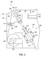
- FIG. 1 is a plan view of one embodiment of a chemical mechanical planarization system of the invention
- FIG. 2 is a sectional view of a polishing station taken along section line 2 — 2 of FIG. 1 ;
- FIG. 3 is an elevation of one embodiment of a lift assembly in a raised position
- FIG. 4 is an elevation of one embodiment of a lift assembly in a lowered position
- FIG. 5 is an elevation of another embodiment of a lift assembly.
- FIG. 1 depicts a plan view of one embodiment of a chemical mechanical planarization system 100 having one or more lift assemblies 108 (shown as two lift assemblies 108 A and 108 B in the embodiment depicted in FIG. 2 ).
- the exemplary system 100 generally comprises a factory interface 102 , a loading robot 104 , and a polishing module 106 .
- the loading robot 104 is disposed proximate the factory interface 102 and the polishing module 106 to facilitate the transfer of substrates 122 therebetween.
- the factory interface 102 generally includes a cleaning module 116 and one or more wafer cassettes 118 .
- An interface robot 120 is employed to transfer substrates 122 between the wafer cassettes 118 , the cleaning module 116 and an input module 124 .
- the input module 124 is positioned to facilitate transfer of substrates 122 between the polishing module 106 and the factory interface 102 by the loading robot 104 .
- unpolished substrates 122 retrieved from the cassettes 118 by the interface robot 120 may be transferred to the input module 124 where the substrates 122 may be accessed by the loading robot 104 while polished substrates 122 returning from the polishing module 106 may be placed in the input module 124 by the loading robot 104 .
- Polished substrates 122 are typically passed from the input module 124 through the cleaning module 116 before the factory interface robot 120 returns the cleaned substrates 122 to the cassettes 118 .
- An example of such a factory interface 102 that may be used to advantage is disclosed in U.S. patent application Ser. No. 09/547,189, filed Apr. 11, 2000, which is hereby incorporated by reference.
- the loading robot 104 is generally positioned proximate the factory interface 102 and the polishing module 106 such that the range of motion provided by the robot 104 facilitates transfer of the substrates 122 therebetween.
- An example of a loading robot 104 is a 4-Link robot, manufactured by Kensington Laboratories, Inc., located in Richmond, Calif.
- the exemplary loading robot 104 has an articulated arm 126 having a rotary actuator 128 at its distal end.
- An edge contact gripper 130 is coupled to the rotary actuator 128 .
- the rotary actuator 128 permits the substrate 122 secured by the gripper 130 to be orientated in either a vertical or a horizontal orientation without contacting the feature side 120 of the substrate 122 and possibly causing scratching or damage to the exposed features. Additionally, the edge contact gripper 130 securely holds the substrate 122 during transfer, thus decreasing the probability that the substrate 122 will become disengaged.
- other types of grippers such as electrostatic grippers, vacuum grippers and mechanical clamps, may be substituted.
- One polishing module 106 that can be used to advantage with the present invention is a Mirra® Chemical Mechanical Polisher, manufactured by Applied Materials, Inc., located in Santa Clara, Calif.
- Other polishing modules 102 including those that use polishing pads, polishing webs, or a combination thereof may also be used to advantage.
- Other systems that benefit include systems that move a substrate relative a polishing surface in a rotational, linearly or in other motion within a plane.
- the exemplary polishing module 106 has a transfer station 136 , a plurality of polishing stations 132 and a carousel 134 disposed on an upper or first side 138 of a machine base 140 .
- the transfer station 136 comprises at least an input buffer station 142 , an output buffer station 144 , a transfer robot 146 , and a load cup assembly 148 .
- the loading robot 104 places the substrate 122 onto the input buffer station 142 .
- the transfer robot 146 has two gripper assemblies, each having pneumatic gripper fingers that grab the substrate 122 by the substrate's edge.
- the transfer robot 146 lifts the substrate 122 from the input buffer station 142 and rotates the gripper and substrate 122 to position the substrate 122 over the load cup assembly 148 , then places the substrate 122 down onto the load cup assembly 148 .
- An example of a transfer station that may be used to advantage is described by Tobin in U.S. patent application Ser. No. 09/314,771, filed Oct. 6, 1999, which is hereby incorporated by reference.
- the carousel 134 is generally described by Tolles in the previously incorporated U.S. Pat. No. 5,804,507. Generally, the carousel 134 is centrally disposed on the base 140 .
- the carousel 134 typically includes a plurality of arms 150 , each supporting a polishing head assembly 152 . Two of the arms 150 depicted in FIG. 1 are shown in phantom such that a polishing surface 131 of one of the polishing stations 132 and the transfer station 136 may be seen.
- the carousel 134 is indexable such that the polishing head assemblies 152 may be moved between the polishing stations 132 and the transfer station 136 .
- a chemical mechanical polishing process is performed at each polishing station 132 .
- a conditioning device 182 is disposed on the base 140 adjacent each polishing station 132 .
- the conditioning device 182 periodically conditions the polishing surface 131 to maintain uniform polishing results.
- FIG. 2 depicts a sectional view of the polishing head assembly 152 supported above the polishing station 132 .
- the polishing head assembly 152 generally comprises a drive system 202 coupled to a polishing head 204 .
- the drive system 202 generally provides rotational motion to the polishing head 204 .
- the polishing head 204 additionally may be actuated to extend towards the polishing station 132 such that the substrate 122 retained in the polishing head 204 may be disposed on the polishing station 132 .
- the drive system 202 is coupled to a carrier 208 that translates upon a rail 210 disposed in the arm 150 of the carousel 134 .
- a ball screw or other linear motion device 212 couples the carrier 208 to the carousel 134 and positions the drive system 202 and polishing head 204 along the rail 210 .
- the polishing head 204 is a TITAN HEADTM wafer carrier manufactured by Applied Materials, Inc., Santa Clara, Calif.
- the polishing head 204 comprises a housing 214 having an extending lip 216 that defines a center recess 218 in which is disposed a bladder 220 .
- the bladder 220 may be comprised of an elastomeric material or thermoplastic elastomer such as ethylene propylene, silicone and HYTRELTM.
- the bladder 220 is coupled to a fluid source (not shown) such that the bladder 220 may be controllably inflated or deflated.
- the bladder 220 when in contact with the substrate 122 , retains the substrate 122 within the polishing head 204 by deflating, thus creating a vacuum between the substrate 122 and the bladder 220 .
- a retaining ring 224 circumscribes the polishing head 204 to retain the substrate 122 within the polishing head 204 while polishing.
- the web of polishing material 252 may have a smooth surface, a textured surface, a surface containing a fixed abrasive or a combination thereof.
- the web of polishing material 252 may be in the form of a roll or sheet (e.g., pad) of material that may be advanced across or releasably fixed to the polishing surface.
- the web of polishing material 252 is releasably fixed by adhesives, vacuum, mechanical clamps or by other holding methods to the platen 230 .
- the web of polishing material 252 may include fixed abrasives.
- Fixed abrasive typically comprises a plurality of abrasive particles suspending in a resin binder that is disposed in discrete elements on a backing sheet. Examples of such fixed abrasive pads are described in U.S. Pat. No. 5,692,950, by Rutherford et al. (issued Dec. 2, 1997) and U.S. Pat. No. 5,453,312, by Haas et al. (issued Sep. 26, 1995), both of which are hereby incorporated by reference.
- the web of polishing material 252 may optionally comprise conventional polishing material without fixed abrasives.
- Conventional polishing material is generally comprised of polyurethane.
- Conventional polishing material typically uses polishing fluids that includes entrained abrasives.
- Subpads used with conventional material are generally lower in hardness (i.e., softer) than the subpads typically used with fixed abrasive webs 252 .
- Conventional material i.e., pads without fixed abrasives is available from Rodel, Inc., of Newark, Del.
- the polishing station 132 generally comprises a platen 230 that is disposed on the base 140 .
- the platen 230 is typically comprised of aluminum.
- the platen 230 is supported above the base 140 by a bearing 238 so that the platen 230 may rotate in relation to the base 140 .
- An area of the base 140 circumscribed by the bearing 238 is open and provides a conduit for the electrical, mechanical, pneumatic, control signals and connections communicating with the platen 230 .
- Conventional bearings, rotary unions and slip rings are provided such that electrical, mechanical, pneumatic, control signals and connections may be coupled between the base 140 and the rotating platen 230 .
- the platen 230 is typically coupled to a motor 232 that provides the rotational motion to the platen 230 .
- the platen 230 has an upper portion 236 that supports the web of polishing material 252 .
- a top surface 260 of the platen 230 contains a center recess 276 extending into the top portion 236 .
- the top portion 236 may optionally include a plurality of passages 244 disposed adjacent to the recess 276 .
- the passages 244 are coupled to a fluid source (not shown). Fluid flowing through the passages 244 may be used to control the temperature of the platen 230 and the polishing material 252 disposed thereon.
- a subpad 278 and a subplate 280 are disposed in the center recess 276 .
- the subpad 278 is typically a plastic, such as polycarbonate or foamed polyurethane. Generally, the hardness or durometer of the subpad may be chosen to produce a particular polishing result.
- the subpad 278 generally maintains the polishing material 252 parallel to the plane of the substrate 122 held in the polishing head 204 and promotes global planarization of the substrate 122 .
- the subplate 280 is positioned between the subpad 278 and the bottom of the recess 276 such that the upper surface of the subpad 278 is coplanar with the top surface 260 of the platen 230 .
- Both the subpad 278 and the subplate 280 optionally contain a plurality of apertures (not shown) that are generally disposed in a pattern such that the polishing motion of the substrate 122 does not cause a discrete portion of the substrate 122 to pass repeatedly over the apertures while polishing as compared to the other portions of the substrate 122 .
- a vacuum port 284 is provided in the recess 276 and is coupled to an external pump 282 . When a vacuum is drawn through the vacuum port 284 , the air removed between the polishing material 252 and the subpad 278 causes the polishing material 252 to be firmly secured to the subpad 278 during polishing.
- An example of such polishing material retention system is disclosed in U.S.
- polishing material 252 252 to the platen 230 , for example adhesives, bonding, electrostatic chucks, mechanical clamps and other retention mechanisms.
- a blast of gas e.g., air
- the air pressure within the recess 276 moves through the apertures (not shown) disposed in the subpad 278 and subplate 280 and lifts the polishing material 252 from the subpad 278 and the top surface 260 of the platen 230 .
- the polishing material 252 rides upon the cushion of air such that it may be freely indexed across the platen 230 .
- the subpad 278 may be a porous material that permits gas (e.g., air) to permeate therethrough and lift the polishing material 252 from the platen 230 .
- gas e.g., air
- the supply roll 240 generally contains a portion of the web of polishing media 252 wound thereon.
- the web of polishing media 252 is fed over a lift member 242 of the lift assembly 108 A and across the top surface 260 of the platen.
- the web of polishing media 252 is fed over a lift member 246 of the lift assembly 108 B and to a take-up roll 248 disposed to the other side of the platen 230 .
- the lift members 242 , 246 may be a roller, a rod, a bar or other member configured to allow the web 252 to move thereover with minimal damage to the web, particulate generation or contamination of the web.
- the supply roll 240 is removably coupled to the platen 230 to facilitate loading another unwind roll containing unused polishing media once the web of polishing media 252 is consumed over the course of polishing a number of substrates.
- the supply roll 240 is coupled to a slip clutch 250 or similar device that prevents the web of polishing media 252 from inadvertently unwinding from the supply roll 240 .
- the supply roll 240 is covered by a housing 254 that protects the supply roll 240 from damage and contamination.
- a gas is disposed in the volume between the housing 254 and the platen 230 which flows out a gap 256 defined between an edge 258 of the housing 254 and the web of polishing media 252 disposed on the lift member 242 .
- the gas flowing through the gap 256 prevents contaminants such as polishing fluids and byproducts from coming in contact with the unused portion of the web of polishing media 252 disposed on the supply roll 240 enclosed by the housing 254 .
- the take-up roll 248 generally is removably coupled to the platen 230 to facilitate removal of used polishing media that is wound thereon.
- the take-up roll 248 is coupled to a tensioning device 262 that keeps the web of polishing media 252 keeps taunt between the supply roll 240 and take-up roll 248 .
- a housing 264 is disposed over the take-up roll 248 protects the take-up roll 248 from damage and contamination.
- the web of polishing media 252 is advanced between the supply roll 240 and take-up roll 248 by an indexing means 266 .
- the indexing means 266 comprises a drive roller 268 and an idler 270 that pinches the web of polishing media 252 therebetween.
- the drive roller 256 generally is coupled the platen 230 .
- the drive roller 256 is connected to a controlled motor such as a stepper and an encoder (motor and encoder not shown).
- the indexing means 266 enables a predetermined length of polishing to be pulled off the supply roll 240 by drive roller 256 as the drive roller 256 is controllably rotated. A corresponding length of polishing is wound on the take-up roll 248 as the web of polishing media 252 is advanced across the platen 230 .
- the lift assemblies 108 A or 108 B is raised to an extended position to maintain the web of polishing media 252 in a spaced-apart relation to the platen 230 .
- the web 252 may be freely advanced without having to overcome surface tension due to fluid disposed between the web and the platen or possibly creating particulate by contacting the backside of the web with the platen while the web is moving.
- FIG. 3 depicts one embodiment of the platen 230 having the lift assembly 108 A in the extended position.
- the lift assembly 108 A is generally lifts the web of polishing material 252 into a spaced-apart relation with the top surface 260 of the platen 230 (and subpad 278 ) defining a gap 300 .
- the lift assembly 108 A generally includes the lift member 242 and a displacement means 302 for moving the lift member 242 between the extended position shown in FIG. 3 and a retracted position shown in FIGS. 2 and 4 .
- the displacement means 302 may include gas pots, springs, linear actuators, pneumatic cylinders, hydraulic cylinders, ball screws, solenoids, and other motion control devices.
- the lift assembly 108 A includes a rod 304 and bearing block 306 .
- the rod 304 is slidably disposed in the bearing block 306 that is coupled to the platen 230 via a plurality of mounting screws 322 .
- the block 306 may have solid, roller or ball bearings such as a pillow block.
- the rod 304 has a first end 308 and a second end 310 .
- the first end 308 of the rod 304 is coupled to the lift member 242 .
- a bearing 312 may be disposed between the rod 304 and lift member 242 to enhance the rotation of the lift member 242 when in the extended position.
- the bearing 312 and lift member 242 may be replaced with a lift member or bar that lifts the web of polishing media 252 .
- the bar should have a radius or chamfered edge to prevent damage to the web 252 as it is indexed across the bar.
- a first collar 314 and a second collar 318 are disposed on the rod 304 .
- the first collar 314 and second collar 318 may be secured in various positions along the length of the rod 304 .
- the collars 314 and 318 include a set screw to fix the collar in relation to the rod 304 .
- the first collar 314 is disposed between the first end 308 of the rod 304 and the block 306 .
- the second collar 318 is disposed between the second end 310 of the rod 304 and the block 304 .
- the first collar 314 captures a spring 316 between the first collar 314 and the block 306 while the second collar 318 may be positioned to limit the extension of the lift member 242 (and thus the length of the gap 300 ).
- the first collar 314 may be positioned along the rod 304 such that the first collar 314 determines the amount of compression on the spring 316 when lift assembly 108 A is in the extended position.
- the spring 316 may be any energy storage device that produces or can be activated to produce an upward force on the rod 304 .
- Such devices include pneumatic cylinders, solenoids, hydraulic cylinders, compression springs, belleville washers, elastomers and the like.
- the spring 316 comprises a coil spring. The spring 316 is selected to provide the force and travel needed to move the web 252 into the spaced-apart relation with the platen 230 when the slip-clutch 250 (and indexing means 266 ) feeds out a length of web 252 and to maintain the gap 300 while the web is advanced across the platen 230 .
- the housing 254 may include a hinge 272 that allowed the edge 258 to follow the movement of the lift assembly 108 A while maintaining the gap 256 (i.e., to prevent the housing from contacting the web when the lift assembly 108 A is in the extended position).
- the housing 264 may be similarly constructed.
- FIG. 4 depicts the platen 230 having the lift assemblies 108 A and 108 B in the retracted position.
- the spring 316 is compressed allowing the lift member 242 to be seated on a bracket 320 that is coupled to the plenum 230 .
- an outer surface 402 of the bearing 312 seats against a mating surface 404 of the bracket 406 .
- the bracket 320 is coupled to the plenum 230 by fasteners 408 , but optionally, the bracket 320 may be integrally incorporated into the plenum 230 .
- the tensioning of the web 252 also seats the lift member 246 of the second lift assembly 108 B on a bracket 414 .
- the second lift assembly 108 B is substantially similar to the first lift assembly 108 A described with reference to FIG. 3 .
- the second lift assembly 108 B generally has a greater bias force than the first lift assembly 108 A that causes the second lift assembly 108 B to unseat (i.e., extend) before and be seated after the first lift assembly 108 A.
- the sequencing of the movement between the first and second lift assemblies 108 A, 108 B keeps the web of polishing material 252 from dragging across the platen 230 or subpad 278 when wound upon the take-up roll 248 .
- the lift assemblies 108 A, 108 B may comprise substantially identical bias forces such that the lift assemblies 108 A, 108 B move substantially simultaneously.
- one embodiment of the second lift assembly 108 A may include a spring 410 that provides a greater bias force that the spring 316 of the first lift assembly 108 A.
- a collar 412 that retains the spring 410 to the second lift assembly 108 B may be positioned to compress the spring 410 more than the spring 316 , thereby generating a greater bias force in the second lift assembly 108 B when the springs 316 and 410 are identical.
- other methods of creating a difference in the bias forces between the springs may be utilized such as using different free lengths, wire diameters, spring materials, spring constants and the like.
- the second lift assembly may be replaced by a roller or other device to guide the polishing media on top of the platen.
- the second lift assembly 108 B depicted in FIG. 4 may be replaced by fixing the member 246 to the platen 230 .
- FIG. 5 depicts another embodiment of a lift assembly 502 .
- the lift assembly 502 is coupled to the platen 230 that is configured substantially the same as described in reference to FIGS. 2 , 3 and 4 except where the indexing means 266 of FIG. 2 is incorporated into the lift assembly 502 .
- the lift assembly 502 includes a lift member 504 that is similar to the lift member 242 described in reference to FIG. 2 .
- the lift member 504 is coupled to the actuator 506 that is coupled to the platen 230 .
- the actuator 506 may be a pneumatic cylinder, a hydraulic cylinder, a lead screw, a solenoid or other linear motion device that can move the lift member 504 to an extended position.
- the actuator 506 may optionally be interfaced with a stroke limiting device 510 to control the distance the lift member 504 travels when the lift assembly 502 is extended.
- stroke limiting devices 510 are commonly offered as options on pneumatic cylinders, but may alternatively comprise threaded adjusters, shaft collars, or mechanical stops.
- polishing material 252 As the lift member 504 moves a predetermined distance, a corresponding predetermined length of polishing material 252 is unwound from the roll 240 . As the lift member 504 returns to the retracted position, the polishing material 252 is advanced across the platen 230 by the tensioning device 262 that winds the polishing material onto the take-up roll 248 .
Landscapes
- Engineering & Computer Science (AREA)
- Mechanical Engineering (AREA)
- Finish Polishing, Edge Sharpening, And Grinding By Specific Grinding Devices (AREA)
Abstract
Generally, a method and system for lifting a web of polishing material is provided. In one embodiment, the system includes a platen that has a first lift member disposed adjacent to a first side and a second lift member disposed adjacent to a second side. The platen is adapted to support the web of polishing media that is disposed between the first and the second lift members. A method includes supporting a web of polishing media on a platen between a first lift member and a second lift member and moving at least the first lift member or the second lift member to an extended position relative the platen that places the web in a spaced-apart relation with the platen.
Description
This application is a continuation application of U.S. patent application Ser. No. 09/651,657, filed Aug. 29, 2000, now U.S. Pat. No. 6,561,884 which is hereby incorporated by reference in its entirety.
1. Field of Invention
Embodiments of the present invention relate generally to a web lift system and a method for lifting a web in a polishing system.
2. Background of Invention
In semiconductor wafer processing, the use of chemical mechanical planarization, or CMP, has gained favor due to the enhanced ability to increase device density on a semiconductor workpiece, or substrate, such as a wafer. As the demand for planarization of layers formed on wafers in semiconductor fabrication increases, the requirement for greater system (i.e., process tool) throughput with less wafer damage and enhanced wafer planarization has also increased.
An exemplary CMP system that addresses these issues is described in U.S. patent application Ser. No. 09/244,456, filed Feb. 4, 1999 to Birang et al., which is incorporated by reference in its entirety. Birang et al. disclose a CMP system having a planarization system that is supplied wafers from cassettes located in an adjacent liquid filled bath. A transfer mechanism, or robot, facilitates the transfer of the wafers from the bath to a transfer station. The transfer station generally contains a load cup that positions wafers into one of four processing heads mounted to a carousel. The carousel moves each processing head sequentially over the load cup to receive a wafer. As the processing heads are loaded, the carousel moves the processing heads and wafers through the planarization stations for polishing. The wafers are planarized by moving the wafer relative to a polishing material in the presence of a slurry or other polishing fluid medium. The polishing material may include an abrasive surface. The slurry typically contains both chemicals and abrasives that aid in the removal of material from the wafer. After completion of the planarization process, the wafer is returned back through the transfer station to the proper cassette located in the bath.
Conventional polishing pads are generally comprised of a foamed polymer having a textured or porous surface. The textured or porous surface functions to retain the polishing fluid that normally contains abrasive slurry on the polishing pad during the polishing operation. The abrasives in slurry provide the mechanical component of the planarization process planarizes (i.e., polishes) the substrate in concert with chemical agents present in the polishing fluid.
One type of polishing material that may be utilized for chemical mechanical polishing is known as a fixed abrasive material. The fixed abrasive material comprises a plurality of abrasive particles suspended in a resin binder that is disposed in discrete elements on a backing sheet. As the abrasive particles are contained in the polishing material itself, systems utilizing fixed abrasive material generally use polishing fluid that do not contain abrasives. Such polishing fluids enhance the service life of their fluid delivery systems.
Both conventional and fixed abrasive polishing material are generally available in stick-down form or in the form of a web. Generally, conventional polishing material may loose ability to adequately retain polishing fluid over the course of polishing a number of substrates as the polishing surface of the material is consumed by the polishing process.
Fixed abrasive material is typically used in web form. Generally, the polishing process wears down the abrasive elements disposed on the web. To maintain a polishing surface that produces uniform polishing results, the web is periodically indexed to remove portions of the web that may have become worn, replacing those portions with an unused portion of the web.
However, indexing the web across a polishing platen is sometimes difficult. The polishing and other fluids that come in contact with the web may cause surface tension or attraction to develop between the web and the underlying surface of the platen. This surface tension must be over-come to accomplish advancement of the web. If the attraction between the web and platen is great, the indexing means may not be able to index the web or the web may become damaged during the indexing process.
Providing a cushion of gas between the web and platen assists in overcoming the attraction between the web and platen. The gas lifts the web to a spaced-apart relation to the platen where the web may be freely indexed. However, providing gas to the area between the web and platen is complicated, and requires rotary union and process tubing to be routed through an already crowded platen.
Therefore, there is a need for a system that lifts a web of polishing material from a platen so that the web may be freely moved across the platen.
One aspect of the present invention generally provides a system for lifting a web of polishing material. In one embodiment, the system includes a platen that has a first lift member disposed adjacent a first side and a second lift member disposed adjacent a second side. The platen is adapted to support the web of polishing media that is disposed between the first and the second lift members. At least one of the lift members has a retracted and an extended position, the extended position adapted to place the web in a spaced-apart relation with the platen. In another embodiment, the system further comprises a web of polishing material and a polishing head adapted to retain the substrate while moving the substrate relative to the web in a polishing pattern.
In another aspect of the invention, a method for lifting a web of polishing material is provided. In one embodiment, the method includes the steps of supporting a web of polishing media on a platen between a first lift member and a second lift member and moving at least one of the first lift member or the second lift member to an extended position relative the platen that places the web in a spaced-apart relation with the platen.
The teachings of the present invention can be readily understood by considering the following detailed description in conjunction with the accompanying drawings, in which:
To facilitate understanding, identical reference numerals have been used, where possible, to designate identical elements that are common to the figures.
The factory interface 102 generally includes a cleaning module 116 and one or more wafer cassettes 118. An interface robot 120 is employed to transfer substrates 122 between the wafer cassettes 118, the cleaning module 116 and an input module 124. The input module 124 is positioned to facilitate transfer of substrates 122 between the polishing module 106 and the factory interface 102 by the loading robot 104. For example, unpolished substrates 122 retrieved from the cassettes 118 by the interface robot 120 may be transferred to the input module 124 where the substrates 122 may be accessed by the loading robot 104 while polished substrates 122 returning from the polishing module 106 may be placed in the input module 124 by the loading robot 104. Polished substrates 122 are typically passed from the input module 124 through the cleaning module 116 before the factory interface robot 120 returns the cleaned substrates 122 to the cassettes 118. An example of such a factory interface 102 that may be used to advantage is disclosed in U.S. patent application Ser. No. 09/547,189, filed Apr. 11, 2000, which is hereby incorporated by reference.
The loading robot 104 is generally positioned proximate the factory interface 102 and the polishing module 106 such that the range of motion provided by the robot 104 facilitates transfer of the substrates 122 therebetween. An example of a loading robot 104 is a 4-Link robot, manufactured by Kensington Laboratories, Inc., located in Richmond, Calif.
The exemplary loading robot 104 has an articulated arm 126 having a rotary actuator 128 at its distal end. An edge contact gripper 130 is coupled to the rotary actuator 128. The rotary actuator 128 permits the substrate 122 secured by the gripper 130 to be orientated in either a vertical or a horizontal orientation without contacting the feature side 120 of the substrate 122 and possibly causing scratching or damage to the exposed features. Additionally, the edge contact gripper 130 securely holds the substrate 122 during transfer, thus decreasing the probability that the substrate 122 will become disengaged. Optionally, other types of grippers, such as electrostatic grippers, vacuum grippers and mechanical clamps, may be substituted.
One polishing module 106 that can be used to advantage with the present invention is a Mirra® Chemical Mechanical Polisher, manufactured by Applied Materials, Inc., located in Santa Clara, Calif. Other polishing modules 102 including those that use polishing pads, polishing webs, or a combination thereof may also be used to advantage. Other systems that benefit include systems that move a substrate relative a polishing surface in a rotational, linearly or in other motion within a plane.
The exemplary polishing module 106 has a transfer station 136, a plurality of polishing stations 132 and a carousel 134 disposed on an upper or first side 138 of a machine base 140. In one embodiment, the transfer station 136 comprises at least an input buffer station 142, an output buffer station 144, a transfer robot 146, and a load cup assembly 148. The loading robot 104 places the substrate 122 onto the input buffer station 142. The transfer robot 146 has two gripper assemblies, each having pneumatic gripper fingers that grab the substrate 122 by the substrate's edge. The transfer robot 146 lifts the substrate 122 from the input buffer station 142 and rotates the gripper and substrate 122 to position the substrate 122 over the load cup assembly 148, then places the substrate 122 down onto the load cup assembly 148. An example of a transfer station that may be used to advantage is described by Tobin in U.S. patent application Ser. No. 09/314,771, filed Oct. 6, 1999, which is hereby incorporated by reference.
The carousel 134 is generally described by Tolles in the previously incorporated U.S. Pat. No. 5,804,507. Generally, the carousel 134 is centrally disposed on the base 140. The carousel 134 typically includes a plurality of arms 150, each supporting a polishing head assembly 152. Two of the arms 150 depicted in FIG. 1 are shown in phantom such that a polishing surface 131 of one of the polishing stations 132 and the transfer station 136 may be seen. The carousel 134 is indexable such that the polishing head assemblies 152 may be moved between the polishing stations 132 and the transfer station 136.
Generally, a chemical mechanical polishing process is performed at each polishing station 132.
A conditioning device 182 is disposed on the base 140 adjacent each polishing station 132. The conditioning device 182 periodically conditions the polishing surface 131 to maintain uniform polishing results.
The drive system 202 is coupled to a carrier 208 that translates upon a rail 210 disposed in the arm 150 of the carousel 134. A ball screw or other linear motion device 212 couples the carrier 208 to the carousel 134 and positions the drive system 202 and polishing head 204 along the rail 210.
In one embodiment, the polishing head 204 is a TITAN HEAD™ wafer carrier manufactured by Applied Materials, Inc., Santa Clara, Calif. Generally, the polishing head 204 comprises a housing 214 having an extending lip 216 that defines a center recess 218 in which is disposed a bladder 220. The bladder 220 may be comprised of an elastomeric material or thermoplastic elastomer such as ethylene propylene, silicone and HYTREL™. The bladder 220 is coupled to a fluid source (not shown) such that the bladder 220 may be controllably inflated or deflated. The bladder 220, when in contact with the substrate 122, retains the substrate 122 within the polishing head 204 by deflating, thus creating a vacuum between the substrate 122 and the bladder 220. A retaining ring 224 circumscribes the polishing head 204 to retain the substrate 122 within the polishing head 204 while polishing.
Disposed between the polishing head assembly 154 and the polishing station 132 is a web of polishing material 252. The web of polishing material 252 may have a smooth surface, a textured surface, a surface containing a fixed abrasive or a combination thereof. The web of polishing material 252 may be in the form of a roll or sheet (e.g., pad) of material that may be advanced across or releasably fixed to the polishing surface. Typically, the web of polishing material 252 is releasably fixed by adhesives, vacuum, mechanical clamps or by other holding methods to the platen 230.
The web of polishing material 252 may include fixed abrasives. Fixed abrasive typically comprises a plurality of abrasive particles suspending in a resin binder that is disposed in discrete elements on a backing sheet. Examples of such fixed abrasive pads are described in U.S. Pat. No. 5,692,950, by Rutherford et al. (issued Dec. 2, 1997) and U.S. Pat. No. 5,453,312, by Haas et al. (issued Sep. 26, 1995), both of which are hereby incorporated by reference.
The web of polishing material 252 may optionally comprise conventional polishing material without fixed abrasives. Conventional polishing material is generally comprised of polyurethane. Conventional polishing material typically uses polishing fluids that includes entrained abrasives. Subpads used with conventional material are generally lower in hardness (i.e., softer) than the subpads typically used with fixed abrasive webs 252. Conventional material (i.e., pads without fixed abrasives) is available from Rodel, Inc., of Newark, Del.
The polishing station 132 generally comprises a platen 230 that is disposed on the base 140. The platen 230 is typically comprised of aluminum. The platen 230 is supported above the base 140 by a bearing 238 so that the platen 230 may rotate in relation to the base 140. An area of the base 140 circumscribed by the bearing 238 is open and provides a conduit for the electrical, mechanical, pneumatic, control signals and connections communicating with the platen 230.
Conventional bearings, rotary unions and slip rings (not shown) are provided such that electrical, mechanical, pneumatic, control signals and connections may be coupled between the base 140 and the rotating platen 230. The platen 230 is typically coupled to a motor 232 that provides the rotational motion to the platen 230.
The platen 230 has an upper portion 236 that supports the web of polishing material 252. A top surface 260 of the platen 230 contains a center recess 276 extending into the top portion 236. The top portion 236 may optionally include a plurality of passages 244 disposed adjacent to the recess 276. The passages 244 are coupled to a fluid source (not shown). Fluid flowing through the passages 244 may be used to control the temperature of the platen 230 and the polishing material 252 disposed thereon.
A subpad 278 and a subplate 280 are disposed in the center recess 276. The subpad 278 is typically a plastic, such as polycarbonate or foamed polyurethane. Generally, the hardness or durometer of the subpad may be chosen to produce a particular polishing result. The subpad 278 generally maintains the polishing material 252 parallel to the plane of the substrate 122 held in the polishing head 204 and promotes global planarization of the substrate 122. The subplate 280 is positioned between the subpad 278 and the bottom of the recess 276 such that the upper surface of the subpad 278 is coplanar with the top surface 260 of the platen 230.
Both the subpad 278 and the subplate 280 optionally contain a plurality of apertures (not shown) that are generally disposed in a pattern such that the polishing motion of the substrate 122 does not cause a discrete portion of the substrate 122 to pass repeatedly over the apertures while polishing as compared to the other portions of the substrate 122. A vacuum port 284 is provided in the recess 276 and is coupled to an external pump 282. When a vacuum is drawn through the vacuum port 284, the air removed between the polishing material 252 and the subpad 278 causes the polishing material 252 to be firmly secured to the subpad 278 during polishing. An example of such polishing material retention system is disclosed in U.S. patent application Ser. No. 09/258,036, filed Feb. 25, 1999, by Sommer et al., which is hereby incorporated by reference. The reader should note that other types of devices may be utilized to fix the polishing material 252 to the platen 230, for example adhesives, bonding, electrostatic chucks, mechanical clamps and other retention mechanisms.
Optionally, to assist in releasing the polishing material 252 from the subpad 278 and platen 230 prior to advancing the polishing material 252, surface tension caused by fluid that may be disposed between the subpad 278 and the polishing material 252, a blast of gas (e.g., air) may be provided through the vacuum port 284 or other port (not shown) into the recess 276 by the pump 282 (or other pump). The air pressure within the recess 276 moves through the apertures (not shown) disposed in the subpad 278 and subplate 280 and lifts the polishing material 252 from the subpad 278 and the top surface 260 of the platen 230. The polishing material 252 rides upon the cushion of air such that it may be freely indexed across the platen 230. Alternatively, the subpad 278 may be a porous material that permits gas (e.g., air) to permeate therethrough and lift the polishing material 252 from the platen 230. Such a method for releasing the web 252 is described in U.S. patent application No. 60/157,303, filed Oct. 1, 1999, by Butterfield, et al., and is hereby incorporated by reference in its entirety.
Mounted to one side of the platen 230 is a supply roll 240. The supply roll 240 generally contains a portion of the web of polishing media 252 wound thereon. The web of polishing media 252 is fed over a lift member 242 of the lift assembly 108A and across the top surface 260 of the platen. The web of polishing media 252 is fed over a lift member 246 of the lift assembly 108B and to a take-up roll 248 disposed to the other side of the platen 230. The lift members 242, 246 may be a roller, a rod, a bar or other member configured to allow the web 252 to move thereover with minimal damage to the web, particulate generation or contamination of the web.
The supply roll 240 is removably coupled to the platen 230 to facilitate loading another unwind roll containing unused polishing media once the web of polishing media 252 is consumed over the course of polishing a number of substrates. The supply roll 240 is coupled to a slip clutch 250 or similar device that prevents the web of polishing media 252 from inadvertently unwinding from the supply roll 240.
The supply roll 240 is covered by a housing 254 that protects the supply roll 240 from damage and contamination. To further prevent contamination of the supply roll 240, a gas is disposed in the volume between the housing 254 and the platen 230 which flows out a gap 256 defined between an edge 258 of the housing 254 and the web of polishing media 252 disposed on the lift member 242. The gas flowing through the gap 256 prevents contaminants such as polishing fluids and byproducts from coming in contact with the unused portion of the web of polishing media 252 disposed on the supply roll 240 enclosed by the housing 254.
The take-up roll 248 generally is removably coupled to the platen 230 to facilitate removal of used polishing media that is wound thereon. The take-up roll 248 is coupled to a tensioning device 262 that keeps the web of polishing media 252 keeps taunt between the supply roll 240 and take-up roll 248. A housing 264 is disposed over the take-up roll 248 protects the take-up roll 248 from damage and contamination.
The web of polishing media 252 is advanced between the supply roll 240 and take-up roll 248 by an indexing means 266. In one embodiment, the indexing means 266 comprises a drive roller 268 and an idler 270 that pinches the web of polishing media 252 therebetween. The drive roller 256 generally is coupled the platen 230. The drive roller 256 is connected to a controlled motor such as a stepper and an encoder (motor and encoder not shown). The indexing means 266 enables a predetermined length of polishing to be pulled off the supply roll 240 by drive roller 256 as the drive roller 256 is controllably rotated. A corresponding length of polishing is wound on the take-up roll 248 as the web of polishing media 252 is advanced across the platen 230.
Before the web of polishing media 252 is advanced across the platen 230, at least one of the lift assemblies 108A or 108B is raised to an extended position to maintain the web of polishing media 252 in a spaced-apart relation to the platen 230. In a spaced-apart relation, the web 252 may be freely advanced without having to overcome surface tension due to fluid disposed between the web and the platen or possibly creating particulate by contacting the backside of the web with the platen while the web is moving.
In one embodiment, the lift assembly 108A includes a rod 304 and bearing block 306. The rod 304 is slidably disposed in the bearing block 306 that is coupled to the platen 230 via a plurality of mounting screws 322. The block 306 may have solid, roller or ball bearings such as a pillow block.
The rod 304 has a first end 308 and a second end 310. The first end 308 of the rod 304 is coupled to the lift member 242. A bearing 312 may be disposed between the rod 304 and lift member 242 to enhance the rotation of the lift member 242 when in the extended position. Alternatively, the bearing 312 and lift member 242 may be replaced with a lift member or bar that lifts the web of polishing media 252. The bar should have a radius or chamfered edge to prevent damage to the web 252 as it is indexed across the bar.
A first collar 314 and a second collar 318 are disposed on the rod 304. The first collar 314 and second collar 318 may be secured in various positions along the length of the rod 304. In one embodiment, the collars 314 and 318 include a set screw to fix the collar in relation to the rod 304.
The first collar 314 is disposed between the first end 308 of the rod 304 and the block 306. The second collar 318 is disposed between the second end 310 of the rod 304 and the block 304. The first collar 314 captures a spring 316 between the first collar 314 and the block 306 while the second collar 318 may be positioned to limit the extension of the lift member 242 (and thus the length of the gap 300). The first collar 314 may be positioned along the rod 304 such that the first collar 314 determines the amount of compression on the spring 316 when lift assembly 108A is in the extended position.
The spring 316 may be any energy storage device that produces or can be activated to produce an upward force on the rod 304. Such devices include pneumatic cylinders, solenoids, hydraulic cylinders, compression springs, belleville washers, elastomers and the like. In one embodiment, the spring 316 comprises a coil spring. The spring 316 is selected to provide the force and travel needed to move the web 252 into the spaced-apart relation with the platen 230 when the slip-clutch 250 (and indexing means 266) feeds out a length of web 252 and to maintain the gap 300 while the web is advanced across the platen 230.
The housing 254 may include a hinge 272 that allowed the edge 258 to follow the movement of the lift assembly 108A while maintaining the gap 256 (i.e., to prevent the housing from contacting the web when the lift assembly 108A is in the extended position). The housing 264 may be similarly constructed.
The tensioning of the web 252 also seats the lift member 246 of the second lift assembly 108B on a bracket 414. The second lift assembly 108B is substantially similar to the first lift assembly 108A described with reference to FIG. 3 . The second lift assembly 108B generally has a greater bias force than the first lift assembly 108A that causes the second lift assembly 108B to unseat (i.e., extend) before and be seated after the first lift assembly 108A. The sequencing of the movement between the first and second lift assemblies 108A, 108B keeps the web of polishing material 252 from dragging across the platen 230 or subpad 278 when wound upon the take-up roll 248. Alternatively, the lift assemblies 108A, 108B may comprise substantially identical bias forces such that the lift assemblies 108A, 108B move substantially simultaneously.
To achieve the sequencing between the first and the second lift assemblies 108A, 108B, one embodiment of the second lift assembly 108A may include a spring 410 that provides a greater bias force that the spring 316 of the first lift assembly 108A. Alternatively, a collar 412 that retains the spring 410 to the second lift assembly 108B may be positioned to compress the spring 410 more than the spring 316, thereby generating a greater bias force in the second lift assembly 108B when the springs 316 and 410 are identical. Optionally, other methods of creating a difference in the bias forces between the springs may be utilized such as using different free lengths, wire diameters, spring materials, spring constants and the like.
In another embodiment where one lift assembly is utilized, the second lift assembly may be replaced by a roller or other device to guide the polishing media on top of the platen. For example, the second lift assembly 108B depicted in FIG. 4 may be replaced by fixing the member 246 to the platen 230.
In one embodiment the lift assembly 502 includes a lift member 504 that is similar to the lift member 242 described in reference to FIG. 2 . The lift member 504 is coupled to the actuator 506 that is coupled to the platen 230. The actuator 506 may be a pneumatic cylinder, a hydraulic cylinder, a lead screw, a solenoid or other linear motion device that can move the lift member 504 to an extended position. The actuator 506 may optionally be interfaced with a stroke limiting device 510 to control the distance the lift member 504 travels when the lift assembly 502 is extended. Such stroke limiting devices 510 are commonly offered as options on pneumatic cylinders, but may alternatively comprise threaded adjusters, shaft collars, or mechanical stops.
As the lift member 504 moves a predetermined distance, a corresponding predetermined length of polishing material 252 is unwound from the roll 240. As the lift member 504 returns to the retracted position, the polishing material 252 is advanced across the platen 230 by the tensioning device 262 that winds the polishing material onto the take-up roll 248.
Although the teachings of the present invention that have been shown and described in detail herein, those skilled in the art can readily devise other varied embodiments that still incorporate the teachings and do not depart from the scope and spirit of the invention.
Claims (15)
1. A method for moving a web of polishing material comprising the steps of:
supporting a portion of the web of polishing material on a platen between a first member and a second member; and
moving at least one of the first or the second members against an underside of the web to an extended position relative the platen that places the portion of the web in a spaced-apart relation with the platen.
2. The method of claim 1 , wherein the step of moving at least one of the first or the second members comprises moving the first member and the second member.
3. The method of claim 1 , wherein the step of moving further comprises unwinding a portion of the web.
4. The method of claim 1 , wherein the step of moving further comprises at least partially extending the first member before extending the second member.
5. The method of claim 1 further comprising the step of winding the web to return any extended member to a retracted position.
6. The method of claim 1 , wherein the step of moving pulls the web from a supply roll.
7. The method of claim 1 , wherein the step of moving the first or the second member further comprises actuating a linear motion device.
8. The method of claim 7 , wherein the linear motion device is a cylinder, solenoid or lead screw.
9. A method for moving a web of polishing material comprising the steps of:
polishing a first substrate on a portion of the web of polishing material supported on a platen; and
mechanically pushing the web of polishing material away from the platen to place the portion of the web of polishing material and the platen in a spaced-apart relation after polishing the substrate.
10. The method of claim 9 further comprising advancing the mechanically spaced web.
11. The method of claim 10 further comprising:
mechanically lowering the mechanically spaced web of polishing material back into contact with the platen; and
polishing a second substrate.
12. The method of claim 11 , wherein the step of mechanioally pushing further comprises:
actuating a first roller guiding the web of polishing material onto an upper surface of the platen away from the platen.
13. The method of claim 12 , wherein the step of mechanically pushing further comprises:
actuating a second roller disposed on a side of the platen opposite the first roller and having the web of polishing material disposed thereover away from the platen.
14. A method for moving a web of polishing material comprising the steps of:
mechanically pushing a portion of the web of polishing material away from a platen adapted to support the web of polishing mateilal during processing;
advancing the mechanically spaced portion of the web of polishing material across the platen;
returning the mechanically spaced portion of the web of polishing material into contact with the platen; and
polishing a substrate on the platen.
15. The method of claim 14 , wherein the step of mechanically pushing further comprises:
moving a roller having the web passing thereover and disposed between a supply roll having another portion of the web of polishing material wound thereon end the platen.
Priority Applications (1)
| Application Number | Priority Date | Filing Date | Title |
|---|---|---|---|
| US10/408,032 US7008303B2 (en) | 2000-08-29 | 2003-04-03 | Web lift system for chemical mechanical planarization |
Applications Claiming Priority (2)
| Application Number | Priority Date | Filing Date | Title |
|---|---|---|---|
| US09/651,657 US6561884B1 (en) | 2000-08-29 | 2000-08-29 | Web lift system for chemical mechanical planarization |
| US10/408,032 US7008303B2 (en) | 2000-08-29 | 2003-04-03 | Web lift system for chemical mechanical planarization |
Related Parent Applications (1)
| Application Number | Title | Priority Date | Filing Date |
|---|---|---|---|
| US09/651,657 Continuation US6561884B1 (en) | 2000-08-29 | 2000-08-29 | Web lift system for chemical mechanical planarization |
Publications (2)
| Publication Number | Publication Date |
|---|---|
| US20030171069A1 US20030171069A1 (en) | 2003-09-11 |
| US7008303B2 true US7008303B2 (en) | 2006-03-07 |
Family
ID=24613687
Family Applications (2)
| Application Number | Title | Priority Date | Filing Date |
|---|---|---|---|
| US09/651,657 Expired - Fee Related US6561884B1 (en) | 2000-08-29 | 2000-08-29 | Web lift system for chemical mechanical planarization |
| US10/408,032 Expired - Fee Related US7008303B2 (en) | 2000-08-29 | 2003-04-03 | Web lift system for chemical mechanical planarization |
Family Applications Before (1)
| Application Number | Title | Priority Date | Filing Date |
|---|---|---|---|
| US09/651,657 Expired - Fee Related US6561884B1 (en) | 2000-08-29 | 2000-08-29 | Web lift system for chemical mechanical planarization |
Country Status (1)
| Country | Link |
|---|---|
| US (2) | US6561884B1 (en) |
Cited By (23)
| Publication number | Priority date | Publication date | Assignee | Title |
|---|---|---|---|---|
| US20080279659A1 (en) * | 2007-05-07 | 2008-11-13 | Lintec Corporation | Transferring device and transferring method |
| US20090191791A1 (en) * | 2008-01-30 | 2009-07-30 | Ebara Corporation | Polishing method and polishing apparatus |
| US20110223838A1 (en) * | 2010-03-12 | 2011-09-15 | Duescher Wayne O | Fixed-spindle and floating-platen abrasive system using spherical mounts |
| US20110223837A1 (en) * | 2010-03-12 | 2011-09-15 | Duescher Wayne O | Fixed-spindle floating-platen workpiece loader apparatus |
| US20110223836A1 (en) * | 2010-03-12 | 2011-09-15 | Duescher Wayne O | Three-point fixed-spindle floating-platen abrasive system |
| US20110223835A1 (en) * | 2010-03-12 | 2011-09-15 | Duescher Wayne O | Three-point spindle-supported floating abrasive platen |
| US8337280B2 (en) | 2010-09-14 | 2012-12-25 | Duescher Wayne O | High speed platen abrading wire-driven rotary workholder |
| US8430717B2 (en) | 2010-10-12 | 2013-04-30 | Wayne O. Duescher | Dynamic action abrasive lapping workholder |
| US8641476B2 (en) | 2011-10-06 | 2014-02-04 | Wayne O. Duescher | Coplanar alignment apparatus for rotary spindles |
| US8647172B2 (en) | 2010-03-12 | 2014-02-11 | Wayne O. Duescher | Wafer pads for fixed-spindle floating-platen lapping |
| US8647170B2 (en) | 2011-10-06 | 2014-02-11 | Wayne O. Duescher | Laser alignment apparatus for rotary spindles |
| US8696405B2 (en) | 2010-03-12 | 2014-04-15 | Wayne O. Duescher | Pivot-balanced floating platen lapping machine |
| US8758088B2 (en) | 2011-10-06 | 2014-06-24 | Wayne O. Duescher | Floating abrading platen configuration |
| US8845394B2 (en) | 2012-10-29 | 2014-09-30 | Wayne O. Duescher | Bellows driven air floatation abrading workholder |
| US8998677B2 (en) | 2012-10-29 | 2015-04-07 | Wayne O. Duescher | Bellows driven floatation-type abrading workholder |
| US8998678B2 (en) | 2012-10-29 | 2015-04-07 | Wayne O. Duescher | Spider arm driven flexible chamber abrading workholder |
| US9011207B2 (en) | 2012-10-29 | 2015-04-21 | Wayne O. Duescher | Flexible diaphragm combination floating and rigid abrading workholder |
| US9039488B2 (en) | 2012-10-29 | 2015-05-26 | Wayne O. Duescher | Pin driven flexible chamber abrading workholder |
| US9199354B2 (en) | 2012-10-29 | 2015-12-01 | Wayne O. Duescher | Flexible diaphragm post-type floating and rigid abrading workholder |
| US9233452B2 (en) | 2012-10-29 | 2016-01-12 | Wayne O. Duescher | Vacuum-grooved membrane abrasive polishing wafer workholder |
| US9604339B2 (en) | 2012-10-29 | 2017-03-28 | Wayne O. Duescher | Vacuum-grooved membrane wafer polishing workholder |
| US10926378B2 (en) | 2017-07-08 | 2021-02-23 | Wayne O. Duescher | Abrasive coated disk islands using magnetic font sheet |
| US11691241B1 (en) * | 2019-08-05 | 2023-07-04 | Keltech Engineering, Inc. | Abrasive lapping head with floating and rigid workpiece carrier |
Families Citing this family (11)
| Publication number | Priority date | Publication date | Assignee | Title |
|---|---|---|---|---|
| US6482072B1 (en) * | 2000-10-26 | 2002-11-19 | Applied Materials, Inc. | Method and apparatus for providing and controlling delivery of a web of polishing material |
| US6808442B1 (en) * | 2001-12-20 | 2004-10-26 | Lam Research Corporation | Apparatus for removal/remaining thickness profile manipulation |
| US6726532B2 (en) * | 2002-07-24 | 2004-04-27 | Taiwan Semiconductor Manufacturing Co., Ltd | Belt tensioning assembly for CMP apparatus |
| US10265719B2 (en) | 2011-04-13 | 2019-04-23 | Durr Megtec, Llc | Method and apparatus for coating discrete patches |
| KR102059028B1 (en) * | 2011-06-03 | 2019-12-24 | 바브콕 앤드 윌콕스 메그텍, 엘엘시 | Web lifter/stabilizer and method |
| CN107571124A (en) * | 2017-10-19 | 2018-01-12 | 江门市霈霖卫浴科技有限公司 | A kind of level Four gradient flexibility sander |
| CN107553273A (en) * | 2017-10-19 | 2018-01-09 | 江门市霈霖卫浴科技有限公司 | Circular water outlet plate automatically grinding platform |
| US11717936B2 (en) * | 2018-09-14 | 2023-08-08 | Applied Materials, Inc. | Methods for a web-based CMP system |
| GB202008190D0 (en) * | 2020-03-04 | 2020-07-15 | Ocado Innovation Ltd | Wheel |
| CN113275667B (en) * | 2021-05-19 | 2022-07-29 | 湖北博英精工科技股份有限公司 | Gear grinding device |
| CN115464519B (en) * | 2022-10-26 | 2024-02-13 | 天津市春鹏预应力钢绞线有限公司 | System for removing oxide layer on surface of metal wire |
Citations (45)
| Publication number | Priority date | Publication date | Assignee | Title |
|---|---|---|---|---|
| US3376578A (en) | 1966-05-31 | 1968-04-02 | Bruce A. Sawyer | Magnetic positioning device |
| US3929551A (en) | 1974-07-11 | 1975-12-30 | Buckbee Mears Co | Sealing apparatus for continuous moving web |
| US4347689A (en) | 1980-10-20 | 1982-09-07 | Verbatim Corporation | Method for burnishing |
| US4373991A (en) | 1982-01-28 | 1983-02-15 | Western Electric Company, Inc. | Methods and apparatus for polishing a semiconductor wafer |
| US4521995A (en) | 1980-05-23 | 1985-06-11 | Disco Co., Ltd. | Wafer attracting and fixing device |
| US4571799A (en) | 1980-12-22 | 1986-02-25 | Anorad Corporation | Method for producing air bearing pads for positioning table |
| US4603867A (en) | 1984-04-02 | 1986-08-05 | Motorola, Inc. | Spinner chuck |
| US4642943A (en) | 1985-11-21 | 1987-02-17 | Taylor Jr Joseph R | Belt abrading apparatus and method |
| JPS62162466A (en) | 1986-01-09 | 1987-07-18 | Rohm Co Ltd | Lapping device for wafer |
| JPH02269553A (en) | 1989-04-06 | 1990-11-02 | Rodeele Nitta Kk | Polishing method and device thereof |
| JPH0328371A (en) | 1989-06-23 | 1991-02-06 | Matsushita Electric Ind Co Ltd | Production of thin film |
| US5036630A (en) | 1990-04-13 | 1991-08-06 | International Business Machines Corporation | Radial uniformity control of semiconductor wafer polishing |
| US5065547A (en) | 1988-06-06 | 1991-11-19 | Speedfam Company, Ltd. | Surface processing machine for hard disks and the like |
| US5076024A (en) | 1990-08-24 | 1991-12-31 | Intelmatec Corporation | Disk polisher assembly |
| US5088240A (en) | 1989-09-22 | 1992-02-18 | Exclusive Design Company, Inc. | Automated rigid-disk finishing system providing in-line process control |
| JPH0453682A (en) | 1990-06-19 | 1992-02-21 | Mitsubishi Electric Corp | Polishing tool |
| US5099615A (en) | 1989-09-22 | 1992-03-31 | Exclusive Design Company, Inc. | Automated rigid-disk finishing system providing in-line process control |
| JPH04250967A (en) | 1990-12-28 | 1992-09-07 | Amitec Kk | Stepping press device for wide belt sander |
| US5209027A (en) | 1989-10-13 | 1993-05-11 | Tdk Corporation | Polishing of the rear surface of a stamper for optical disk reproduction |
| US5276999A (en) | 1990-06-09 | 1994-01-11 | Bando Kiko Co., Ltd. | Machine for polishing surface of glass plate |
| US5377451A (en) | 1993-02-23 | 1995-01-03 | Memc Electronic Materials, Inc. | Wafer polishing apparatus and method |
| US5399125A (en) | 1993-06-11 | 1995-03-21 | Dozier; Robert L. | Belt grinder |
| JPH07111256A (en) | 1993-10-13 | 1995-04-25 | Toshiba Corp | Semiconductor manufacturing apparatus |
| US5423716A (en) | 1994-01-05 | 1995-06-13 | Strasbaugh; Alan | Wafer-handling apparatus having a resilient membrane which holds wafer when a vacuum is applied |
| US5476413A (en) | 1993-09-30 | 1995-12-19 | Shin-Etsu Handotai Co., Ltd. | Apparatus for polishing the periphery portion of a wafer |
| US5486129A (en) | 1993-08-25 | 1996-01-23 | Micron Technology, Inc. | System and method for real-time control of semiconductor a wafer polishing, and a polishing head |
| US5490808A (en) | 1993-01-28 | 1996-02-13 | Minnesota Mining And Manufacturing Company | Abrasive attachment system for rotative abrading applications |
| US5531861A (en) | 1993-09-29 | 1996-07-02 | Motorola, Inc. | Chemical-mechanical-polishing pad cleaning process for use during the fabrication of semiconductor devices |
| US5536202A (en) | 1994-07-27 | 1996-07-16 | Texas Instruments Incorporated | Semiconductor substrate conditioning head having a plurality of geometries formed in a surface thereof for pad conditioning during chemical-mechanical polish |
| US5558568A (en) | 1994-10-11 | 1996-09-24 | Ontrak Systems, Inc. | Wafer polishing machine with fluid bearings |
| EP0756917A1 (en) | 1994-04-22 | 1997-02-05 | Kabushiki Kaisha Toshiba | Separation type grinding surface plate and grinding apparatus using same |
| US5624299A (en) | 1993-12-27 | 1997-04-29 | Applied Materials, Inc. | Chemical mechanical polishing apparatus with improved carrier and method of use |
| EP0774323A2 (en) | 1995-10-27 | 1997-05-21 | Applied Materials, Inc. | Apparatus and method for polishing substrates |
| US5635083A (en) | 1993-08-06 | 1997-06-03 | Intel Corporation | Method and apparatus for chemical-mechanical polishing using pneumatic pressure applied to the backside of a substrate |
| JPH09225821A (en) | 1996-02-27 | 1997-09-02 | Ebara Corp | Polishing device and method |
| EP0818272A1 (en) | 1996-07-12 | 1998-01-14 | Applied Materials, Inc. | Holding a polishing pad on a platen in a chemical mechanical polishing system |
| US5722877A (en) | 1996-10-11 | 1998-03-03 | Lam Research Corporation | Technique for improving within-wafer non-uniformity of material removal for performing CMP |
| US6062959A (en) | 1997-11-05 | 2000-05-16 | Aplex Group | Polishing system including a hydrostatic fluid bearing support |
| US6135859A (en) | 1999-04-30 | 2000-10-24 | Applied Materials, Inc. | Chemical mechanical polishing with a polishing sheet and a support sheet |
| EP1052063A1 (en) | 1999-05-03 | 2000-11-15 | Applied Materials, Inc. | System for chemical mechanical planarization |
| JP2001071250A (en) | 1999-07-09 | 2001-03-21 | Applied Materials Inc | Fixed abrasive belt polisher |
| US6241585B1 (en) | 1999-06-25 | 2001-06-05 | Applied Materials, Inc. | Apparatus and method for chemical mechanical polishing |
| US6244944B1 (en) | 1999-08-31 | 2001-06-12 | Micron Technology, Inc. | Method and apparatus for supporting and cleaning a polishing pad for chemical-mechanical planarization of microelectronic substrates |
| US6273796B1 (en) * | 1999-09-01 | 2001-08-14 | Micron Technology, Inc. | Method and apparatus for planarizing a microelectronic substrate with a tilted planarizing surface |
| US6273800B1 (en) | 1999-08-31 | 2001-08-14 | Micron Technology, Inc. | Method and apparatus for supporting a polishing pad during chemical-mechanical planarization of microelectronic substrates |
Family Cites Families (92)
| Publication number | Priority date | Publication date | Assignee | Title |
|---|---|---|---|---|
| US585317A (en) * | 1897-06-29 | And erwin lavens | ||
| DE225093C (en) | ||||
| US1353967A (en) * | 1919-10-29 | 1920-09-28 | William A Lorenz | Disk grinding-machine |
| US1665749A (en) * | 1924-03-24 | 1928-04-10 | Mattison Machine Works | Double-belt sander |
| US2646654A (en) | 1950-03-17 | 1953-07-28 | Minnesota Mining & Mfg | Device for dressing coated abrasive belts |
| DE1037308B (en) | 1957-01-11 | 1958-08-21 | Buetfering Maschfab Geb | Device for cleaning sanding belts |
| DE1104379B (en) | 1959-09-30 | 1961-04-06 | Albert Fezer | Suction head with conical sealing collar |
| US4412400A (en) * | 1980-10-20 | 1983-11-01 | Verbatim Corporation | Apparatus for burnishing |
| JPS5937051A (en) | 1982-08-25 | 1984-02-29 | Toray Ind Inc | Dust adhesion prevention device for air cleaner |
| JPS60228070A (en) | 1985-03-25 | 1985-11-13 | Hitachi Ltd | Both sides polishing machine |
| US4918870A (en) | 1986-05-16 | 1990-04-24 | Siltec Corporation | Floating subcarriers for wafer polishing apparatus |
| JPH079896B2 (en) | 1988-10-06 | 1995-02-01 | 信越半導体株式会社 | Polishing equipment |
| US4910155A (en) | 1988-10-28 | 1990-03-20 | International Business Machines Corporation | Wafer flood polishing |
| US5234867A (en) | 1992-05-27 | 1993-08-10 | Micron Technology, Inc. | Method for planarizing semiconductor wafers with a non-circular polishing pad |
| DE69206685T2 (en) | 1991-06-06 | 1996-07-04 | Commissariat Energie Atomique | Polishing machine with a tensioned fine grinding belt and an improved workpiece carrier head |
| US5212910A (en) | 1991-07-09 | 1993-05-25 | Intel Corporation | Composite polishing pad for semiconductor process |
| JPH06509519A (en) | 1991-07-30 | 1994-10-27 | ミネソタ・マイニング・アンド・マニュファクチュアリング・カンパニー | Coated abrasive tool dressed with multi-point cutting tool |
| US5197999A (en) | 1991-09-30 | 1993-03-30 | National Semiconductor Corporation | Polishing pad for planarization |
| JP2985490B2 (en) * | 1992-02-28 | 1999-11-29 | 信越半導体株式会社 | Heat removal method of polishing machine |
| US5329732A (en) | 1992-06-15 | 1994-07-19 | Speedfam Corporation | Wafer polishing method and apparatus |
| US5498199A (en) | 1992-06-15 | 1996-03-12 | Speedfam Corporation | Wafer polishing method and apparatus |
| US5310455A (en) | 1992-07-10 | 1994-05-10 | Lsi Logic Corporation | Techniques for assembling polishing pads for chemi-mechanical polishing of silicon wafers |
| US5299393A (en) | 1992-07-21 | 1994-04-05 | International Business Machines Corporation | Slurry containment device for polishing semiconductor wafers |
| US5216843A (en) | 1992-09-24 | 1993-06-08 | Intel Corporation | Polishing pad conditioning apparatus for wafer planarization process |
| US5384986A (en) | 1992-09-24 | 1995-01-31 | Ebara Corporation | Polishing apparatus |
| US5562529A (en) | 1992-10-08 | 1996-10-08 | Fujitsu Limited | Apparatus and method for uniformly polishing a wafer |
| US5232875A (en) | 1992-10-15 | 1993-08-03 | Micron Technology, Inc. | Method and apparatus for improving planarity of chemical-mechanical planarization operations |
| US5398459A (en) | 1992-11-27 | 1995-03-21 | Kabushiki Kaisha Toshiba | Method and apparatus for polishing a workpiece |
| US5442828A (en) | 1992-11-30 | 1995-08-22 | Ontrak Systems, Inc. | Double-sided wafer scrubber with a wet submersing silicon wafer indexer |
| US5487697A (en) | 1993-02-09 | 1996-01-30 | Rodel, Inc. | Polishing apparatus and method using a rotary work holder travelling down a rail for polishing a workpiece with linear pads |
| US5554064A (en) | 1993-08-06 | 1996-09-10 | Intel Corporation | Orbital motion chemical-mechanical polishing apparatus and method of fabrication |
| US5443416A (en) | 1993-09-09 | 1995-08-22 | Cybeq Systems Incorporated | Rotary union for coupling fluids in a wafer polishing apparatus |
| JP2513426B2 (en) | 1993-09-20 | 1996-07-03 | 日本電気株式会社 | Wafer polishing machine |
| US5584746A (en) | 1993-10-18 | 1996-12-17 | Shin-Etsu Handotai Co., Ltd. | Method of polishing semiconductor wafers and apparatus therefor |
| US5564965A (en) | 1993-12-14 | 1996-10-15 | Shin-Etsu Handotai Co., Ltd. | Polishing member and wafer polishing apparatus |
| US5582534A (en) | 1993-12-27 | 1996-12-10 | Applied Materials, Inc. | Orbital chemical mechanical polishing apparatus and method |
| US5643053A (en) * | 1993-12-27 | 1997-07-01 | Applied Materials, Inc. | Chemical mechanical polishing apparatus with improved polishing control |
| US5547417A (en) | 1994-03-21 | 1996-08-20 | Intel Corporation | Method and apparatus for conditioning a semiconductor polishing pad |
| US5595529A (en) | 1994-03-28 | 1997-01-21 | Speedfam Corporation | Dual column abrading machine |
| JPH07297195A (en) | 1994-04-27 | 1995-11-10 | Speedfam Co Ltd | Method and apparatus for flattening semiconductor device |
| US5562524A (en) | 1994-05-04 | 1996-10-08 | Gill, Jr.; Gerald L. | Polishing apparatus |
| JPH07328915A (en) * | 1994-06-03 | 1995-12-19 | Ebara Corp | Polishing device |
| US5548505A (en) | 1994-07-15 | 1996-08-20 | Oktrak Systems, Inc. | Scrubber control system |
| US5534106A (en) | 1994-07-26 | 1996-07-09 | Kabushiki Kaisha Toshiba | Apparatus for processing semiconductor wafers |
| DE69512971T2 (en) * | 1994-08-09 | 2000-05-18 | Ontrak Systems Inc., Milpitas | Linear polisher and wafer planarization process |
| JP2933488B2 (en) * | 1994-08-10 | 1999-08-16 | 日本電気株式会社 | Polishing method and polishing apparatus |
| JP3418467B2 (en) * | 1994-10-19 | 2003-06-23 | 株式会社荏原製作所 | Polishing equipment |
| JP3566417B2 (en) | 1994-10-31 | 2004-09-15 | 株式会社荏原製作所 | Polishing equipment |
| US5791969A (en) | 1994-11-01 | 1998-08-11 | Lund; Douglas E. | System and method of automatically polishing semiconductor wafers |
| US5643044A (en) | 1994-11-01 | 1997-07-01 | Lund; Douglas E. | Automatic chemical and mechanical polishing system for semiconductor wafers |
| US5549511A (en) | 1994-12-06 | 1996-08-27 | International Business Machines Corporation | Variable travel carrier device and method for planarizing semiconductor wafers |
| US5522965A (en) | 1994-12-12 | 1996-06-04 | Texas Instruments Incorporated | Compact system and method for chemical-mechanical polishing utilizing energy coupled to the polishing pad/water interface |
| JPH08168953A (en) | 1994-12-16 | 1996-07-02 | Ebara Corp | Dressing device |
| US5527424A (en) | 1995-01-30 | 1996-06-18 | Motorola, Inc. | Preconditioner for a polishing pad and method for using the same |
| US5558563A (en) | 1995-02-23 | 1996-09-24 | International Business Machines Corporation | Method and apparatus for uniform polishing of a substrate |
| US5597346A (en) | 1995-03-09 | 1997-01-28 | Texas Instruments Incorporated | Method and apparatus for holding a semiconductor wafer during a chemical mechanical polish (CMP) process |
| JPH08252765A (en) * | 1995-03-16 | 1996-10-01 | Fujitsu Ltd | Polishing device, polishing cloth conveying device, polishing cloth sticking device, and polishing cloth |
| JP3483648B2 (en) * | 1995-03-24 | 2004-01-06 | 東芝機械株式会社 | Polishing equipment |
| US5533923A (en) | 1995-04-10 | 1996-07-09 | Applied Materials, Inc. | Chemical-mechanical polishing pad providing polishing unformity |
| US5908530A (en) * | 1995-05-18 | 1999-06-01 | Obsidian, Inc. | Apparatus for chemical mechanical polishing |
| US5578529A (en) | 1995-06-02 | 1996-11-26 | Motorola Inc. | Method for using rinse spray bar in chemical mechanical polishing |
| US5554065A (en) | 1995-06-07 | 1996-09-10 | Clover; Richmond B. | Vertically stacked planarization machine |
| US5599423A (en) | 1995-06-30 | 1997-02-04 | Applied Materials, Inc. | Apparatus and method for simulating and optimizing a chemical mechanical polishing system |
| US5569062A (en) | 1995-07-03 | 1996-10-29 | Speedfam Corporation | Polishing pad conditioning |
| JPH0929634A (en) | 1995-07-13 | 1997-02-04 | Riken Korandamu Kk | Dressing device for polishing belt |
| US5645471A (en) | 1995-08-11 | 1997-07-08 | Minnesota Mining And Manufacturing Company | Method of texturing a substrate using an abrasive article having multiple abrasive natures |
| US5611943A (en) | 1995-09-29 | 1997-03-18 | Intel Corporation | Method and apparatus for conditioning of chemical-mechanical polishing pads |
| US5938507A (en) | 1995-10-27 | 1999-08-17 | Applied Materials, Inc. | Linear conditioner apparatus for a chemical mechanical polishing system |
| US5961372A (en) * | 1995-12-05 | 1999-10-05 | Applied Materials, Inc. | Substrate belt polisher |
| US5792709A (en) * | 1995-12-19 | 1998-08-11 | Micron Technology, Inc. | High-speed planarizing apparatus and method for chemical mechanical planarization of semiconductor wafers |
| US5575706A (en) | 1996-01-11 | 1996-11-19 | Taiwan Semiconductor Manufacturing Company Ltd. | Chemical/mechanical planarization (CMP) apparatus and polish method |
| JPH09248753A (en) | 1996-03-11 | 1997-09-22 | Sanshin:Kk | Method and device for flatly polishing surface of device wafer |
| US6022807A (en) * | 1996-04-24 | 2000-02-08 | Micro Processing Technology, Inc. | Method for fabricating an integrated circuit |
| US5800248A (en) * | 1996-04-26 | 1998-09-01 | Ontrak Systems Inc. | Control of chemical-mechanical polishing rate across a substrate surface |
| US5916012A (en) * | 1996-04-26 | 1999-06-29 | Lam Research Corporation | Control of chemical-mechanical polishing rate across a substrate surface for a linear polisher |
| US5762536A (en) * | 1996-04-26 | 1998-06-09 | Lam Research Corporation | Sensors for a linear polisher |
| JP2873937B2 (en) * | 1996-05-24 | 1999-03-24 | 工業技術院長 | Optical microfabrication method for glass |
| JP3611404B2 (en) * | 1996-06-21 | 2005-01-19 | 株式会社荏原製作所 | Polishing device |
| JPH1034514A (en) * | 1996-07-24 | 1998-02-10 | Sanshin:Kk | Surface polishing method and device therefor |
| US5795218A (en) * | 1996-09-30 | 1998-08-18 | Micron Technology, Inc. | Polishing pad with elongated microcolumns |
| US5747386A (en) * | 1996-10-03 | 1998-05-05 | Micron Technology, Inc. | Rotary coupling |
| US5899801A (en) * | 1996-10-31 | 1999-05-04 | Applied Materials, Inc. | Method and apparatus for removing a substrate from a polishing pad in a chemical mechanical polishing system |
| US5871390A (en) * | 1997-02-06 | 1999-02-16 | Lam Research Corporation | Method and apparatus for aligning and tensioning a pad/belt used in linear planarization for chemical mechanical polishing |
| US6149506A (en) * | 1998-10-07 | 2000-11-21 | Keltech Engineering | Lapping apparatus and method for high speed lapping with a rotatable abrasive platen |
| US5873769A (en) * | 1997-05-30 | 1999-02-23 | Industrial Technology Research Institute | Temperature compensated chemical mechanical polishing to achieve uniform removal rates |
| GB9712457D0 (en) * | 1997-06-17 | 1997-08-20 | Smiths Industries Plc | Electrical connection |
| US6102777A (en) * | 1998-03-06 | 2000-08-15 | Keltech Engineering | Lapping apparatus and method for high speed lapping with a rotatable abrasive platen |
| US5897426A (en) * | 1998-04-24 | 1999-04-27 | Applied Materials, Inc. | Chemical mechanical polishing with multiple polishing pads |
| US6103628A (en) * | 1998-12-01 | 2000-08-15 | Nutool, Inc. | Reverse linear polisher with loadable housing |
| US6244935B1 (en) * | 1999-02-04 | 2001-06-12 | Applied Materials, Inc. | Apparatus and methods for chemical mechanical polishing with an advanceable polishing sheet |
| US6491570B1 (en) | 1999-02-25 | 2002-12-10 | Applied Materials, Inc. | Polishing media stabilizer |
| US6220942B1 (en) * | 1999-04-02 | 2001-04-24 | Applied Materials, Inc. | CMP platen with patterned surface |
-
2000
- 2000-08-29 US US09/651,657 patent/US6561884B1/en not_active Expired - Fee Related
-
2003
- 2003-04-03 US US10/408,032 patent/US7008303B2/en not_active Expired - Fee Related
Patent Citations (48)
| Publication number | Priority date | Publication date | Assignee | Title |
|---|---|---|---|---|
| US3376578A (en) | 1966-05-31 | 1968-04-02 | Bruce A. Sawyer | Magnetic positioning device |
| US3929551A (en) | 1974-07-11 | 1975-12-30 | Buckbee Mears Co | Sealing apparatus for continuous moving web |
| US4521995A (en) | 1980-05-23 | 1985-06-11 | Disco Co., Ltd. | Wafer attracting and fixing device |
| US4347689A (en) | 1980-10-20 | 1982-09-07 | Verbatim Corporation | Method for burnishing |
| US4571799A (en) | 1980-12-22 | 1986-02-25 | Anorad Corporation | Method for producing air bearing pads for positioning table |
| US4373991A (en) | 1982-01-28 | 1983-02-15 | Western Electric Company, Inc. | Methods and apparatus for polishing a semiconductor wafer |
| US4603867A (en) | 1984-04-02 | 1986-08-05 | Motorola, Inc. | Spinner chuck |
| US4642943A (en) | 1985-11-21 | 1987-02-17 | Taylor Jr Joseph R | Belt abrading apparatus and method |
| JPS62162466A (en) | 1986-01-09 | 1987-07-18 | Rohm Co Ltd | Lapping device for wafer |
| US5065547A (en) | 1988-06-06 | 1991-11-19 | Speedfam Company, Ltd. | Surface processing machine for hard disks and the like |
| JPH02269553A (en) | 1989-04-06 | 1990-11-02 | Rodeele Nitta Kk | Polishing method and device thereof |
| JPH0328371A (en) | 1989-06-23 | 1991-02-06 | Matsushita Electric Ind Co Ltd | Production of thin film |
| US5088240A (en) | 1989-09-22 | 1992-02-18 | Exclusive Design Company, Inc. | Automated rigid-disk finishing system providing in-line process control |
| US5099615A (en) | 1989-09-22 | 1992-03-31 | Exclusive Design Company, Inc. | Automated rigid-disk finishing system providing in-line process control |
| US5209027A (en) | 1989-10-13 | 1993-05-11 | Tdk Corporation | Polishing of the rear surface of a stamper for optical disk reproduction |
| US5036630A (en) | 1990-04-13 | 1991-08-06 | International Business Machines Corporation | Radial uniformity control of semiconductor wafer polishing |
| US5276999A (en) | 1990-06-09 | 1994-01-11 | Bando Kiko Co., Ltd. | Machine for polishing surface of glass plate |
| JPH0453682A (en) | 1990-06-19 | 1992-02-21 | Mitsubishi Electric Corp | Polishing tool |
| US5076024A (en) | 1990-08-24 | 1991-12-31 | Intelmatec Corporation | Disk polisher assembly |
| JPH04250967A (en) | 1990-12-28 | 1992-09-07 | Amitec Kk | Stepping press device for wide belt sander |
| US5490808A (en) | 1993-01-28 | 1996-02-13 | Minnesota Mining And Manufacturing Company | Abrasive attachment system for rotative abrading applications |
| US5377451A (en) | 1993-02-23 | 1995-01-03 | Memc Electronic Materials, Inc. | Wafer polishing apparatus and method |
| US5399125A (en) | 1993-06-11 | 1995-03-21 | Dozier; Robert L. | Belt grinder |
| US5635083A (en) | 1993-08-06 | 1997-06-03 | Intel Corporation | Method and apparatus for chemical-mechanical polishing using pneumatic pressure applied to the backside of a substrate |
| US5486129A (en) | 1993-08-25 | 1996-01-23 | Micron Technology, Inc. | System and method for real-time control of semiconductor a wafer polishing, and a polishing head |
| US5531861A (en) | 1993-09-29 | 1996-07-02 | Motorola, Inc. | Chemical-mechanical-polishing pad cleaning process for use during the fabrication of semiconductor devices |
| US5476413A (en) | 1993-09-30 | 1995-12-19 | Shin-Etsu Handotai Co., Ltd. | Apparatus for polishing the periphery portion of a wafer |
| JPH07111256A (en) | 1993-10-13 | 1995-04-25 | Toshiba Corp | Semiconductor manufacturing apparatus |
| US5624299A (en) | 1993-12-27 | 1997-04-29 | Applied Materials, Inc. | Chemical mechanical polishing apparatus with improved carrier and method of use |
| US5423716A (en) | 1994-01-05 | 1995-06-13 | Strasbaugh; Alan | Wafer-handling apparatus having a resilient membrane which holds wafer when a vacuum is applied |
| EP0756917A1 (en) | 1994-04-22 | 1997-02-05 | Kabushiki Kaisha Toshiba | Separation type grinding surface plate and grinding apparatus using same |
| US5536202A (en) | 1994-07-27 | 1996-07-16 | Texas Instruments Incorporated | Semiconductor substrate conditioning head having a plurality of geometries formed in a surface thereof for pad conditioning during chemical-mechanical polish |
| US5558568A (en) | 1994-10-11 | 1996-09-24 | Ontrak Systems, Inc. | Wafer polishing machine with fluid bearings |
| US5593344A (en) | 1994-10-11 | 1997-01-14 | Ontrak Systems, Inc. | Wafer polishing machine with fluid bearings and drive systems |
| EP0774323A2 (en) | 1995-10-27 | 1997-05-21 | Applied Materials, Inc. | Apparatus and method for polishing substrates |
| JPH09225821A (en) | 1996-02-27 | 1997-09-02 | Ebara Corp | Polishing device and method |
| EP0818272A1 (en) | 1996-07-12 | 1998-01-14 | Applied Materials, Inc. | Holding a polishing pad on a platen in a chemical mechanical polishing system |
| US5722877A (en) | 1996-10-11 | 1998-03-03 | Lam Research Corporation | Technique for improving within-wafer non-uniformity of material removal for performing CMP |
| US6062959A (en) | 1997-11-05 | 2000-05-16 | Aplex Group | Polishing system including a hydrostatic fluid bearing support |
| US6135859A (en) | 1999-04-30 | 2000-10-24 | Applied Materials, Inc. | Chemical mechanical polishing with a polishing sheet and a support sheet |
| EP1052063A1 (en) | 1999-05-03 | 2000-11-15 | Applied Materials, Inc. | System for chemical mechanical planarization |
| JP2000353679A (en) | 1999-05-03 | 2000-12-19 | Applied Materials Inc | System for chemical and mechanical planarization |
| US6241585B1 (en) | 1999-06-25 | 2001-06-05 | Applied Materials, Inc. | Apparatus and method for chemical mechanical polishing |
| JP2001071250A (en) | 1999-07-09 | 2001-03-21 | Applied Materials Inc | Fixed abrasive belt polisher |
| US6244944B1 (en) | 1999-08-31 | 2001-06-12 | Micron Technology, Inc. | Method and apparatus for supporting and cleaning a polishing pad for chemical-mechanical planarization of microelectronic substrates |
| US6273800B1 (en) | 1999-08-31 | 2001-08-14 | Micron Technology, Inc. | Method and apparatus for supporting a polishing pad during chemical-mechanical planarization of microelectronic substrates |
| US6361417B2 (en) * | 1999-08-31 | 2002-03-26 | Micron Technology, Inc. | Method and apparatus for supporting a polishing pad during chemical-mechanical planarization of microelectronic substrates |
| US6273796B1 (en) * | 1999-09-01 | 2001-08-14 | Micron Technology, Inc. | Method and apparatus for planarizing a microelectronic substrate with a tilted planarizing surface |
Non-Patent Citations (5)
| Title |
|---|
| Butterfield, et al., "Platen With Web Release Apparatus", U.S. Appl. No. 09/676,395, filed Sep. 29, 2000. |
| Franklin, et al., "Integrated Platen Assembly for a Chemical Mechanical Planarization System", U.S. Appl. No. 09/931,156, filed Aug. 16, 2001. |
| Li, et al., "Platen for Retaining Polishing Material", U.S. Appl. No. 09/709,769, filed Nov. 10, 2000. |
| Sommer, et al., "Polishing Media Stabilizer", U.S. Appl. No. 09/258,036, filed Feb. 25, 1999. |
| White, et al., "Web Lift System for Chemical Mechanical Planarization", U.S. Appl. No. 09/651,657, filed Aug. 29, 2000. |
Cited By (30)
| Publication number | Priority date | Publication date | Assignee | Title |
|---|---|---|---|---|
| US7875144B2 (en) * | 2007-05-07 | 2011-01-25 | Lintec Corporation | Transferring device and transferring method |
| US20080279659A1 (en) * | 2007-05-07 | 2008-11-13 | Lintec Corporation | Transferring device and transferring method |
| US8430716B2 (en) | 2008-01-30 | 2013-04-30 | Ebara Corporation | Polishing method and polishing apparatus |
| US20090191791A1 (en) * | 2008-01-30 | 2009-07-30 | Ebara Corporation | Polishing method and polishing apparatus |
| US8647171B2 (en) | 2010-03-12 | 2014-02-11 | Wayne O. Duescher | Fixed-spindle floating-platen workpiece loader apparatus |
| US8696405B2 (en) | 2010-03-12 | 2014-04-15 | Wayne O. Duescher | Pivot-balanced floating platen lapping machine |
| US20110223835A1 (en) * | 2010-03-12 | 2011-09-15 | Duescher Wayne O | Three-point spindle-supported floating abrasive platen |
| US8328600B2 (en) | 2010-03-12 | 2012-12-11 | Duescher Wayne O | Workpiece spindles supported floating abrasive platen |
| US8740668B2 (en) | 2010-03-12 | 2014-06-03 | Wayne O. Duescher | Three-point spindle-supported floating abrasive platen |
| US20110223837A1 (en) * | 2010-03-12 | 2011-09-15 | Duescher Wayne O | Fixed-spindle floating-platen workpiece loader apparatus |
| US20110223836A1 (en) * | 2010-03-12 | 2011-09-15 | Duescher Wayne O | Three-point fixed-spindle floating-platen abrasive system |
| US8500515B2 (en) | 2010-03-12 | 2013-08-06 | Wayne O. Duescher | Fixed-spindle and floating-platen abrasive system using spherical mounts |
| US8602842B2 (en) | 2010-03-12 | 2013-12-10 | Wayne O. Duescher | Three-point fixed-spindle floating-platen abrasive system |
| US8647172B2 (en) | 2010-03-12 | 2014-02-11 | Wayne O. Duescher | Wafer pads for fixed-spindle floating-platen lapping |
| US20110223838A1 (en) * | 2010-03-12 | 2011-09-15 | Duescher Wayne O | Fixed-spindle and floating-platen abrasive system using spherical mounts |
| US8337280B2 (en) | 2010-09-14 | 2012-12-25 | Duescher Wayne O | High speed platen abrading wire-driven rotary workholder |
| US8430717B2 (en) | 2010-10-12 | 2013-04-30 | Wayne O. Duescher | Dynamic action abrasive lapping workholder |
| US8641476B2 (en) | 2011-10-06 | 2014-02-04 | Wayne O. Duescher | Coplanar alignment apparatus for rotary spindles |
| US8647170B2 (en) | 2011-10-06 | 2014-02-11 | Wayne O. Duescher | Laser alignment apparatus for rotary spindles |
| US8758088B2 (en) | 2011-10-06 | 2014-06-24 | Wayne O. Duescher | Floating abrading platen configuration |
| US8998677B2 (en) | 2012-10-29 | 2015-04-07 | Wayne O. Duescher | Bellows driven floatation-type abrading workholder |
| US8845394B2 (en) | 2012-10-29 | 2014-09-30 | Wayne O. Duescher | Bellows driven air floatation abrading workholder |
| US8998678B2 (en) | 2012-10-29 | 2015-04-07 | Wayne O. Duescher | Spider arm driven flexible chamber abrading workholder |
| US9011207B2 (en) | 2012-10-29 | 2015-04-21 | Wayne O. Duescher | Flexible diaphragm combination floating and rigid abrading workholder |
| US9039488B2 (en) | 2012-10-29 | 2015-05-26 | Wayne O. Duescher | Pin driven flexible chamber abrading workholder |
| US9199354B2 (en) | 2012-10-29 | 2015-12-01 | Wayne O. Duescher | Flexible diaphragm post-type floating and rigid abrading workholder |
| US9233452B2 (en) | 2012-10-29 | 2016-01-12 | Wayne O. Duescher | Vacuum-grooved membrane abrasive polishing wafer workholder |
| US9604339B2 (en) | 2012-10-29 | 2017-03-28 | Wayne O. Duescher | Vacuum-grooved membrane wafer polishing workholder |
| US10926378B2 (en) | 2017-07-08 | 2021-02-23 | Wayne O. Duescher | Abrasive coated disk islands using magnetic font sheet |
| US11691241B1 (en) * | 2019-08-05 | 2023-07-04 | Keltech Engineering, Inc. | Abrasive lapping head with floating and rigid workpiece carrier |
Also Published As
| Publication number | Publication date |
|---|---|
| US6561884B1 (en) | 2003-05-13 |
| US20030171069A1 (en) | 2003-09-11 |
Similar Documents
| Publication | Publication Date | Title |
|---|---|---|
| US7008303B2 (en) | Web lift system for chemical mechanical planarization | |
| EP1052059A2 (en) | Method for chemical mechanical planarization | |
| US6241585B1 (en) | Apparatus and method for chemical mechanical polishing | |
| KR100315722B1 (en) | Polishing machine for flattening substrate surface | |
| US7040964B2 (en) | Polishing media stabilizer | |
| KR100638290B1 (en) | Wafer conveying apparatus, wafer polishing apparatus and wafer manufacturing method | |
| US6604988B2 (en) | Polishing apparatus and method with belt drive system adapted to extend the lifetime of a refreshing polishing belt provided therein | |
| US20070212976A1 (en) | Smart polishing media assembly for planarizing substrates | |
| US6677239B2 (en) | Methods and compositions for chemical mechanical polishing | |
| US6817923B2 (en) | Chemical mechanical processing system with mobile load cup | |
| US20030066604A1 (en) | Integrated platen assembly for a chemical mechanical planarization | |
| US6482072B1 (en) | Method and apparatus for providing and controlling delivery of a web of polishing material | |
| EP1052060A2 (en) | Method for chemical mechanical planarization | |
| WO2002028595A1 (en) | Polishing apparatus and method with a refreshing polishing belt and loadable housing | |
| US8012000B2 (en) | Extended pad life for ECMP and barrier removal | |
| US6659849B1 (en) | Platen with debris control for chemical mechanical planarization | |
| US20020016136A1 (en) | Conditioner for polishing pads | |
| US20030224678A1 (en) | Web pad design for chemical mechanical polishing | |
| US6612914B2 (en) | Platen with lateral web tensioner | |
| US6679755B1 (en) | Chemical mechanical planarization system | |
| EP1088622A2 (en) | Platen with web release apparatus | |
| US7048607B1 (en) | System and method for chemical mechanical planarization | |
| US20240082982A1 (en) | Processing system, pad transporting apparatus, liquid-receiving apparatus, and polishing apparatus | |
| JP2005524971A (en) | Air platen for leading and trailing edge control | |
| EP1106305A2 (en) | Chemical mechanical planarization system |
Legal Events
| Date | Code | Title | Description |
|---|---|---|---|
| AS | Assignment |
Owner name: APPLIED MATERIALS, INC., CALIFORNIA Free format text: ASSIGNMENT OF ASSIGNORS INTEREST;ASSIGNORS:WHITE, JOHN M.;SOMMER, PHILLIP R.;SOMEKH, SASSON;REEL/FRAME:013945/0565;SIGNING DATES FROM 20000815 TO 20000829 |
|
| CC | Certificate of correction | ||
| FPAY | Fee payment |
Year of fee payment: 4 |
|
| REMI | Maintenance fee reminder mailed | ||
| LAPS | Lapse for failure to pay maintenance fees | ||
| STCH | Information on status: patent discontinuation |
Free format text: PATENT EXPIRED DUE TO NONPAYMENT OF MAINTENANCE FEES UNDER 37 CFR 1.362 |
|
| FP | Lapsed due to failure to pay maintenance fee |
Effective date: 20140307 |