US699404A - Printer's chase. - Google Patents
Printer's chase. Download PDFInfo
- Publication number
- US699404A US699404A US3571800A US1900035718A US699404A US 699404 A US699404 A US 699404A US 3571800 A US3571800 A US 3571800A US 1900035718 A US1900035718 A US 1900035718A US 699404 A US699404 A US 699404A
- Authority
- US
- United States
- Prior art keywords
- pieces
- corner
- chase
- bars
- mortise
- Prior art date
- Legal status (The legal status is an assumption and is not a legal conclusion. Google has not performed a legal analysis and makes no representation as to the accuracy of the status listed.)
- Expired - Lifetime
Links
Images
Classifications
-
- B—PERFORMING OPERATIONS; TRANSPORTING
- B41—PRINTING; LINING MACHINES; TYPEWRITERS; STAMPS
- B41B—MACHINES OR ACCESSORIES FOR MAKING, SETTING, OR DISTRIBUTING TYPE; TYPE; PHOTOGRAPHIC OR PHOTOELECTRIC COMPOSING DEVICES
- B41B1/00—Elements or appliances for hand composition; Chases, quoins, or galleys
- B41B1/18—Chases
Definitions
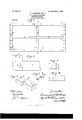
- Figure 1 is a top plan of a chase constructed according to my invention, including cross-pieces which render the device suitable for book-work.
- Fig.2 is an enlarged plan of one of the corner-pieces with the end bar removed from same, side bar attached to same, and partly broken away.
- Fig. 3 is an end elevation of one of said bars.
- Fig. 4 is a side elevation of one of the corner-pieces.
- Fig. 5 is a perspective view of one of the intel-mediate members used in adapting the device for book-work.
- Fig. (5 is a perspective view, partly broken away, of the middle part of one of the cross-pieces used in book-work.
- the entire chase may be lifted by raising opposite corner-pieces.
- the weight of the side bars will hold same in proper engagement with the corner-pieces.
- the side bars 1 and end bars 2 are provided with a tenon or dovetail 3 at each end.
- the corner-pieces 4 are each provided with sockets or mortises 5 for receiving said dovetails.
- the members 6 are provided with a similar mortise 5 at each end and the mortise 7 on the inner side.
- the mortise 7 is of uniform diameter from top to bottom, while the mortises 5 are preferably made of less diameter at the bottom than at the top, as illustrated in Fig. 4.
- the dovetails 3 are also of less diameter at the bottom than at the top, as shown in Fig. 3.
- said dovetails are made in the form of a truncated wedge with trapezoidal base.
- the cross-pieces 8 and 9 are provided at each end with a dovetail 10 of suitable form to fit the mortise 7.
- the crosspieces 8 and 9 are each provided with a mortise 11 at their middle part, which permits said cross-pieces to lie in the same horizontal plane.
- Each corner-piece 4 has one of its mortises 5 located farther from the corner than its other mortise 5. This provides for slightly altering the dimensions of the chase by interchanging the corner-pieces.
- the parts will be connected substantially as shown in Fig. 1.
- the members 6 and cross-pieces 8 and 9 will be omitted and the side and end bars will be connected directly with the corner-pieces at each end.
- the operator will merely lift the side and end bars free from the corner-pieces and will substitute other side and end bars of the desired lengths.
- a printers chase comprising the cornerpieces, and the detachable side and end bars connecting said corner-pieces and forming therewitharigid rectangular frame; said corner-pieces and bars being separable only When oppositely moved transversely to a plane extending through all of said sections, and each of said corner-pieces having one of its ends for attachment to said bars farther removed from the corner than its other end for attachment to said bars, substantially as described.
- a printers chase comprising the cornerpieces, and the detachable side and end bars connecting said corner-pieces and forming therewith a rigid rectangular frame; said corner-pieces and bars being separable only when oppositely moved transversely to a plane extending .through all of said sections; said bars having all of their attaching ends of uniform shape and size, and said cornerpieces each having their attaching parts formed oppositely to said attaching ends and adapted for receiving and securing any of said attaching ends and each of said cornerpieces having one of its attaching parts located farther from the corner than its other attaching part, substantially as described.
- a printers chase comprising the cornerpieces, and the detachable side and end bars connecting said corner-pieces and forming therewith a rigid rectangular frame; said corner-pieces and bars being separable only when oppositely moved transversely to a plane extending through all of said sections; said bars having at each end a dovetail in the form of a truncated Wedge with trapezoidal base, and said corner-pieces having mortises fitting said dovetails, and all of said dovetails being of uniform size and shape, and adapted to similarly fit in any of said mortises, each of said corner-pieces having one of its mortises located farther from the corner than its other mortise, substantially as described.
Landscapes
- Accessory Devices And Overall Control Thereof (AREA)
Description
Patented May 6, I902.
I]. s. MBGREAL, Decd.
A. S. MBGREAL, Administratrix.
PRINTERS CHASE.
(Application filed Nov. 7, 1900.)
N4, J 1% 1 P 7 7 u vw 6 W/ 3 m w m? y 7 7 M 6 t 0,0 A Wfl f3 Urrn STATES ATENT OFFICE.
DOMINICK S. MCGREAL, OF CHICAGO, ILLINOIS; ANNA S. MCGREAL, ADMIN- ISTRATRIX OF SAID DOMINICK S. MCGREAL, DECEASED, ASSIGNOR OF ONE-HALF TO JACOB P. RAPP, OF CHICAGO, ILLINOIS.
PRINTERS CHASE.
SPECIFICATION forming part of Letters Patent No. 699,404, dated May 6, 1902. Application filed November 7, 1900. Serial No. 35,718. (No model.)
and complementary parts all of suitable con-.
struction to permit an operator to readily combine same in the form of printers chases of different dimensions. It will be understood that in using the old solid chases it is necessary to provide a large amount of furniture for locking up forms of difierent dimensions. For convenience it has been necessary to provide a large number of solid chases of diiferent sizes. NVith my construction it is necessary only to provide side and end bars of diderent lengths. These can be combined with corner-pieces, so as to alter the chase to a large number of different dimensions.
It is well known that in all printing-houses a vast amount of time and labor is lost in looking for wooden furniture to dress up a solid chase which is too large to accommodate the form. An additional difiioulty is that after the compositor has locked his small form in a large chase he finds his form sprung from the stone, thus necessitating his unlockin g and doctoring the furniture to obviate the spring. The operator may have to do this several times before having a perfect lock-up. By the use of my construction the operator can always make his chase of. suitable size for the form. This will avoid the working up of the leads, slugs, quadrats, 850., caused by a springy form.
The construction and operation of my device will be understood from the following description with reference to the accompanying drawings, in which Figure 1 is a top plan of a chase constructed according to my invention, including cross-pieces which render the device suitable for book-work. Fig.2 is an enlarged plan of one of the corner-pieces with the end bar removed from same, side bar attached to same, and partly broken away. Fig. 3 is an end elevation of one of said bars. Fig. 4 is a side elevation of one of the corner-pieces. Fig. 5 is a perspective view of one of the intel-mediate members used in adapting the device for book-work. Fig. (5 is a perspective view, partly broken away, of the middle part of one of the cross-pieces used in book-work.
The entire chase may be lifted by raising opposite corner-pieces. The weight of the side bars will hold same in proper engagement with the corner-pieces.
1n the form shown the side bars 1 and end bars 2 are provided with a tenon or dovetail 3 at each end. The corner-pieces 4 are each provided with sockets or mortises 5 for receiving said dovetails. The members 6 are provided with a similar mortise 5 at each end and the mortise 7 on the inner side. The mortise 7 is of uniform diameter from top to bottom, while the mortises 5 are preferably made of less diameter at the bottom than at the top, as illustrated in Fig. 4. The dovetails 3 are also of less diameter at the bottom than at the top, as shown in Fig. 3. Thus it will be seen that said dovetails are made in the form of a truncated wedge with trapezoidal base. This form of joint insures that the parts will be held firmly in place when pressed home and permits same to be readily separated. The cross-pieces 8 and 9 are provided at each end with a dovetail 10 of suitable form to fit the mortise 7. The crosspieces 8 and 9 are each provided with a mortise 11 at their middle part, which permits said cross-pieces to lie in the same horizontal plane.
It will be understood that additional side bars 1 and end bars 2 of different lengths will be provided to be substituted for those shown. The cross-pieces 8 and 9 will also be provided in different lengths suitable for book-work of diiferent dimensions.
Each corner-piece 4 has one of its mortises 5 located farther from the corner than its other mortise 5. This provides for slightly altering the dimensions of the chase by interchanging the corner-pieces.
The operation of my device is as follows: 10:;
For book-work the parts will be connected substantially as shown in Fig. 1. For ordinary job-Work the members 6 and cross-pieces 8 and 9 will be omitted and the side and end bars will be connected directly with the corner-pieces at each end. To alter the dimensions of the chase, the operator will merely lift the side and end bars free from the corner-pieces and will substitute other side and end bars of the desired lengths.
It will be understood that some of the details in the structure shown may be altered without departing from the spirit of my invention. I therefore do not confine myself to such details except as hereinafter limited in the claims.
What I claim as my invention, and desire to secure by Letters Patent, is
1. A printers chase comprising the cornerpieces, and the detachable side and end bars connecting said corner-pieces and forming therewitharigid rectangular frame; said corner-pieces and bars being separable only When oppositely moved transversely to a plane extending through all of said sections, and each of said corner-pieces having one of its ends for attachment to said bars farther removed from the corner than its other end for attachment to said bars, substantially as described.
2. A printers chase comprising the cornerpieces, and the detachable side and end bars connecting said corner-pieces and forming therewith a rigid rectangular frame; said corner-pieces and bars being separable only when oppositely moved transversely to a plane extending .through all of said sections; said bars having all of their attaching ends of uniform shape and size, and said cornerpieces each having their attaching parts formed oppositely to said attaching ends and adapted for receiving and securing any of said attaching ends and each of said cornerpieces having one of its attaching parts located farther from the corner than its other attaching part, substantially as described.
3. A printers chase comprising the cornerpieces, and the detachable side and end bars connecting said corner-pieces and forming therewith a rigid rectangular frame; said corner-pieces and bars being separable only when oppositely moved transversely to a plane extending through all of said sections; said bars having at each end a dovetail in the form of a truncated Wedge with trapezoidal base, and said corner-pieces having mortises fitting said dovetails, and all of said dovetails being of uniform size and shape, and adapted to similarly fit in any of said mortises, each of said corner-pieces having one of its mortises located farther from the corner than its other mortise, substantially as described.
Signed at Chicago this 3d day of November, 1900.
DOMINIOK S. MCGREAL.
Witnesses:
WM. R. RUMMLER, GLEN O. STEPHENS.
Priority Applications (1)
| Application Number | Priority Date | Filing Date | Title |
|---|---|---|---|
| US3571800A US699404A (en) | 1900-11-07 | 1900-11-07 | Printer's chase. |
Applications Claiming Priority (1)
| Application Number | Priority Date | Filing Date | Title |
|---|---|---|---|
| US3571800A US699404A (en) | 1900-11-07 | 1900-11-07 | Printer's chase. |
Publications (1)
| Publication Number | Publication Date |
|---|---|
| US699404A true US699404A (en) | 1902-05-06 |
Family
ID=2767934
Family Applications (1)
| Application Number | Title | Priority Date | Filing Date |
|---|---|---|---|
| US3571800A Expired - Lifetime US699404A (en) | 1900-11-07 | 1900-11-07 | Printer's chase. |
Country Status (1)
| Country | Link |
|---|---|
| US (1) | US699404A (en) |
Cited By (1)
| Publication number | Priority date | Publication date | Assignee | Title |
|---|---|---|---|---|
| US3075261A (en) * | 1959-09-29 | 1963-01-29 | Nat Sales System Inc | Advertising mat kit |
-
1900
- 1900-11-07 US US3571800A patent/US699404A/en not_active Expired - Lifetime
Cited By (1)
| Publication number | Priority date | Publication date | Assignee | Title |
|---|---|---|---|---|
| US3075261A (en) * | 1959-09-29 | 1963-01-29 | Nat Sales System Inc | Advertising mat kit |
Similar Documents
| Publication | Publication Date | Title |
|---|---|---|
| US699404A (en) | Printer's chase. | |
| US408213A (en) | Brsck-mold | |
| US87339A (en) | Improvement in printers furniture | |
| US406862A (en) | Stereotype-plate and base | |
| US675529A (en) | Printer's chase. | |
| US973323A (en) | Mold for making hollow building-blocks. | |
| US1394307A (en) | Printer's chase | |
| US414145A (en) | Foot-brush | |
| US417478A (en) | Printer s chase | |
| US386675A (en) | Paper or bill file | |
| US51898A (en) | Self and joseph m | |
| US324699A (en) | Quoin and side-stick | |
| US234877A (en) | o o o o o p | |
| US724530A (en) | Combined printer's galley and chase. | |
| US682840A (en) | Printer's chase. | |
| US842198A (en) | Mounting-block for printing-plates. | |
| US807177A (en) | Skeleton-frame rule for printing. | |
| US212228A (en) | Improvement in apparatus for casting stereotypes | |
| US698587A (en) | Printing-block for oil-cloth-printing machines. | |
| US371274A (en) | Printer s furniture | |
| US691967A (en) | Separable or sectional printer's chase. | |
| US2583495A (en) | Printer's chase | |
| US616782A (en) | Hans goldzier | |
| US2251227A (en) | Type chase | |
| US979586A (en) | Line unit-case for printing-machines. |