US6952616B2 - Medical lead and method for electrode attachment - Google Patents
Medical lead and method for electrode attachment Download PDFInfo
- Publication number
- US6952616B2 US6952616B2 US09/822,728 US82272801A US6952616B2 US 6952616 B2 US6952616 B2 US 6952616B2 US 82272801 A US82272801 A US 82272801A US 6952616 B2 US6952616 B2 US 6952616B2
- Authority
- US
- United States
- Prior art keywords
- conductor
- region
- lead
- insulator
- lead body
- Prior art date
- Legal status (The legal status is an assumption and is not a legal conclusion. Google has not performed a legal analysis and makes no representation as to the accuracy of the status listed.)
- Expired - Lifetime, expires
Links
- 238000000034 method Methods 0.000 title description 11
- 239000004020 conductor Substances 0.000 claims description 113
- 238000003466 welding Methods 0.000 claims description 48
- 239000012212 insulator Substances 0.000 claims description 36
- 239000000853 adhesive Substances 0.000 claims description 8
- 230000001070 adhesive effect Effects 0.000 claims description 8
- 238000002513 implantation Methods 0.000 abstract description 2
- 239000011810 insulating material Substances 0.000 description 9
- 238000004519 manufacturing process Methods 0.000 description 8
- 239000000463 material Substances 0.000 description 8
- 229910052751 metal Inorganic materials 0.000 description 8
- 239000002184 metal Substances 0.000 description 8
- BASFCYQUMIYNBI-UHFFFAOYSA-N platinum Chemical compound [Pt] BASFCYQUMIYNBI-UHFFFAOYSA-N 0.000 description 6
- 208000027418 Wounds and injury Diseases 0.000 description 5
- 238000013461 design Methods 0.000 description 5
- 210000001519 tissue Anatomy 0.000 description 5
- 238000002788 crimping Methods 0.000 description 4
- 238000010438 heat treatment Methods 0.000 description 4
- 229910001220 stainless steel Inorganic materials 0.000 description 4
- 239000010935 stainless steel Substances 0.000 description 4
- BQCADISMDOOEFD-UHFFFAOYSA-N Silver Chemical compound [Ag] BQCADISMDOOEFD-UHFFFAOYSA-N 0.000 description 3
- 230000000747 cardiac effect Effects 0.000 description 3
- 238000010276 construction Methods 0.000 description 3
- PCHJSUWPFVWCPO-UHFFFAOYSA-N gold Chemical compound [Au] PCHJSUWPFVWCPO-UHFFFAOYSA-N 0.000 description 3
- 229910052737 gold Inorganic materials 0.000 description 3
- 239000010931 gold Substances 0.000 description 3
- 210000000056 organ Anatomy 0.000 description 3
- 229910052697 platinum Inorganic materials 0.000 description 3
- -1 polyethylene Polymers 0.000 description 3
- 229910052709 silver Inorganic materials 0.000 description 3
- 239000004332 silver Substances 0.000 description 3
- RYGMFSIKBFXOCR-UHFFFAOYSA-N Copper Chemical compound [Cu] RYGMFSIKBFXOCR-UHFFFAOYSA-N 0.000 description 2
- 229910002835 Pt–Ir Inorganic materials 0.000 description 2
- 229910045601 alloy Inorganic materials 0.000 description 2
- 239000000956 alloy Substances 0.000 description 2
- 229910052802 copper Inorganic materials 0.000 description 2
- 239000010949 copper Substances 0.000 description 2
- 238000005530 etching Methods 0.000 description 2
- 150000002739 metals Chemical class 0.000 description 2
- 239000000203 mixture Substances 0.000 description 2
- 238000000465 moulding Methods 0.000 description 2
- 238000012552 review Methods 0.000 description 2
- 229910052720 vanadium Inorganic materials 0.000 description 2
- LEONUFNNVUYDNQ-UHFFFAOYSA-N vanadium atom Chemical compound [V] LEONUFNNVUYDNQ-UHFFFAOYSA-N 0.000 description 2
- 229910052779 Neodymium Inorganic materials 0.000 description 1
- 239000004698 Polyethylene Substances 0.000 description 1
- 239000004642 Polyimide Substances 0.000 description 1
- 238000002679 ablation Methods 0.000 description 1
- 230000000712 assembly Effects 0.000 description 1
- 238000000429 assembly Methods 0.000 description 1
- 239000011248 coating agent Substances 0.000 description 1
- 238000000576 coating method Methods 0.000 description 1
- 230000000694 effects Effects 0.000 description 1
- 229920000840 ethylene tetrafluoroethylene copolymer Polymers 0.000 description 1
- 239000002223 garnet Substances 0.000 description 1
- 210000005003 heart tissue Anatomy 0.000 description 1
- 208000014674 injury Diseases 0.000 description 1
- 238000003780 insertion Methods 0.000 description 1
- 230000037431 insertion Effects 0.000 description 1
- 238000013507 mapping Methods 0.000 description 1
- 239000000155 melt Substances 0.000 description 1
- 238000002844 melting Methods 0.000 description 1
- 230000008018 melting Effects 0.000 description 1
- 238000012806 monitoring device Methods 0.000 description 1
- 230000002107 myocardial effect Effects 0.000 description 1
- QEFYFXOXNSNQGX-UHFFFAOYSA-N neodymium atom Chemical compound [Nd] QEFYFXOXNSNQGX-UHFFFAOYSA-N 0.000 description 1
- 210000000944 nerve tissue Anatomy 0.000 description 1
- 230000000926 neurological effect Effects 0.000 description 1
- 210000000578 peripheral nerve Anatomy 0.000 description 1
- 239000004033 plastic Substances 0.000 description 1
- 229920003023 plastic Polymers 0.000 description 1
- HWLDNSXPUQTBOD-UHFFFAOYSA-N platinum-iridium alloy Chemical compound [Ir].[Pt] HWLDNSXPUQTBOD-UHFFFAOYSA-N 0.000 description 1
- 229920000573 polyethylene Polymers 0.000 description 1
- 229920001721 polyimide Polymers 0.000 description 1
- 229920001296 polysiloxane Polymers 0.000 description 1
- 239000004810 polytetrafluoroethylene Substances 0.000 description 1
- 229920001343 polytetrafluoroethylene Polymers 0.000 description 1
- 229920002635 polyurethane Polymers 0.000 description 1
- 239000004814 polyurethane Substances 0.000 description 1
- 229920000915 polyvinyl chloride Polymers 0.000 description 1
- 239000004800 polyvinyl chloride Substances 0.000 description 1
- 239000007787 solid Substances 0.000 description 1
- 210000001032 spinal nerve Anatomy 0.000 description 1
- 230000000638 stimulation Effects 0.000 description 1
- 230000008733 trauma Effects 0.000 description 1
- 210000003462 vein Anatomy 0.000 description 1
Images


Classifications
-
- A—HUMAN NECESSITIES
- A61—MEDICAL OR VETERINARY SCIENCE; HYGIENE
- A61N—ELECTROTHERAPY; MAGNETOTHERAPY; RADIATION THERAPY; ULTRASOUND THERAPY
- A61N1/00—Electrotherapy; Circuits therefor
- A61N1/02—Details
- A61N1/04—Electrodes
- A61N1/05—Electrodes for implantation or insertion into the body, e.g. heart electrode
- A61N1/056—Transvascular endocardial electrode systems
Definitions
- the present invention relates to a medical leads and particularly to medical leads having unitary construction.
- Implantable leads form an electrical connection between a pulse generator or other electronic device and a tissue or structure in the body.
- leads transmit electric signals used to stimulate cardiac or nerve tissue in one direction and signals generated by sensors placed in proximity to particular organs or tissues in the opposite direction.
- Leads typically include one or more electrodes at the lead's distal end. The electrodes are designed to form an electrical connection with a tissue or organ.
- most leads also include a lead connector at the lead body's proximal end. Lead connectors are adapted to electrically and mechanically connect leads to the pulse generators or other electronic medical devices.
- a conductor connects the electrode to the lead connector. Commonly, the conductor takes the form of a single or multifilar wire coil.
- an insulating material typically surrounds the conductors.
- Spinal chord stimulation leads are typically formed with individually insulated conductors surrounded by a separate lead body tube. Together, the conductor and the insulating material form the lead body. The lead body couples the lead connector at the proximal end with the electrode at the distal end.
- Band electrodes may also be connected to a conductor by etching away a region of insulator, applying a coating of electrically conductive adhesive, and then placing the band electrode around the conductor.
- This etching method is complex, not amenable to automation, and expensive. Therefore, a need exists for a method that reduces complexity and is easily automated to reduce production costs.
- band electrodes are electrically connected to coiled conductors by placing a soft metal in a hole cut into an insulating sleeve. An electrode is placed over the metal and crimped or swaged to bring the electrode, soft metal and coiled conductors into electrical contact and to secure the electrode the lead body.
- the crimping or swaging method of connection results in electrical connections between the conductor and the band electrode that may fail. Further, swaging to electrically connect an electrode to a conductor is time consuming and difficult to implement with the modern reduced diameter leads. Hence, a need exists for an improved manufacturing technique to secure band electrodes to conductors that reduces the time, complexity and cost while increasing reliability.
- a medical lead in accordance with the present invention includes a lead body, at least one band electrode and at least one band conductor.
- the lead body extends the length of the lead and includes a seamless insulator between the proximal and distal ends of the lead insulating at least one conductor within the lead body.
- At least one band electrode and at least one band connector are secured between the proximal and distal end of the lead body and electrically connected to the conductor.
- the band connector is positioned adjacent the proximal end of the lead body and the band electrode is positioned adjacent the distal end of the lead body. Further, the band electrode and the band connector may be electrically connected to the conductor by welding to a conductive pad within a welding region.
- FIG. 1 illustrates a perspective view of a lead in accordance with the present invention
- FIG. 2 illustrates a longitudinal cross-sectional view of a of a lead showing an embodiment of the connection between a coiled conductor and a band with a conductive pad;
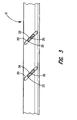
- FIG. 3 illustrates a top view of a lead, as shown in FIG. 2 , without the band;
- FIG. 4 illustrates a longitudinal cross-sectional view of a of a lead showing the connection between a coiled conductor and a band with an elongated conductive element
- FIG. 5 illustrates a top view of a lead, as shown in FIG. 4 , without the band;
- FIG. 6A illustrates a cross-sectional longitudinal view of a band electrode, as shown in FIGS. 4 and 5 ;
- FIG. 6B illustrates and end view of the band electrode, as in FIG. 6 A.
- the present invention provides a medical lead and a method for lead manufacture.
- the invention is described generally in the context of a neurostimulating lead and a method for manufacturing a neurostimulating lead as a specific example for illustrative purpose only.
- the appended claims are not intended to be limited to any specific example or embodiment described in this patent.
- leads in accordance with the present invention may be used for a wide variety of applications including, but not limited to, leads and catheters for use with cardiac monitoring devices, neurostimulating devices, neuromonitoring devices or other medical devices using leads or catheters.
- the reference numerals are generally repeated where identical elements appear in more than one figure.
- FIG. 1 illustrates an embodiment of a seam-less lead 10 in accordance with the present invention.
- Leads designed for neurostimulation typically have two or more longitudinally spaced band electrode 14 and the lead's distal end and an equivalent number of band connectors 15 at the proximal end to connect the lead to the particularly medical device.
- Lead 10 includes a lead body 12 , four band electrodes 14 and four connector bands 15 , for exemplary purposes.
- Connector bands 15 are shown disposed about a sleeve 19 secured over the lead body to increase the diameter allowing insertion of a reduced diameter lead's connector into a standard connector port of a medical device.
- one or more band electrode 14 and one or more band connectors 15 are provided.
- Lead 10 is generally configured to transmit an electric signal from a pulse generator (not shown) to a spinal nerve or peripheral nerve.
- band electrodes 14 are typically located at the distal end of lead 10 .
- Lead body 12 includes flexible lead insulator surrounding one or more conductors. The conductors are electrically coupled to band electrodes 14 at the distal end and band connectors 15 at the proximal end of lead 10 .
- lead body 12 is flexible, elastomeric structure having a round cross-section. Alternatively, lead body's cross-section could be any number of shapes appropriate for the specific application.
- the diameter of lead body 12 may vary between the proximal end and distal end of lead 10 . Depending on the particular application, the diameter of lead body 12 may be smaller than 2 French for neurological and myocardial mapping/ablation leads and can be sizes larger than 12 French for other applications.
- the lead insulator is generally configured to insulate the conductors and to present a smooth biocompatible external surface to body tissues and form a continuous and seam-less structure between the proximal and distal ends of lead 10 .
- the insulator material is typically selected based on biocompatibility, biostability and durability for the particular application.
- the insulator material may be silicone, polyurethane, polyethylene, polyimide, polyvinylchloride, PTFE, ETFE, or other materials known to those skilled in the art.
- alloys and blends of these materials may also be formulated to control the relative flexibility, torqueability, and pushability of the lead.
- the conductors 22 may take the form of solid wires, drawn-filled-tube (DFT), drawn-brazed-strand (DBS), stranded cables or other forms that will be recognized by those skilled in the art.
- the conductors may be composed of stainless steel, MP35N, or other conductive materials known to those skilled in the art. The number, size, and composition of the conductors will depend on particular application for the lead.
- At least one band electrode 14 is positioned at the distal end of lead body 12 to electrically contact a target tissue or organ and at least one band connector 15 is positioned at the proximal end of lead body 12 to electrically connect the conductors to the neurostimulator.
- the band electrodes 14 and band connectors 15 are typically made of a conductive material such as platinum, gold, silver, platinum-iridium, stainless steel, MP35N or other conductive metals or alloys thereof known to those skilled in the art.
- Band electrodes 14 and band connectors 15 typically composed of a material thin enough to allow for welding of the elements to the underlying conductive pad, as discussed below.
- band electrodes 14 are typically between 1 and 10 millimeters long and have a diameter between about 2 and about 8 French but are more typically between 4 and 6 French.
- band connections 15 have a size and configuration appropriate to connect the lead to a particular neurostimulator.
- FIG. 2 illustrates the details of an embodiment of the connection between a conductor 22 and band electrode 14 in accordance with the present invention.
- band electrodes 14 and band connectors 15 should be considered synonymous and band electrode 14 will be used throughout the remainder of the description.
- Band electrode 14 is disposed about lead body. Lead body 12 is shown with four spirally wound conductors 22 connected at two locations to band electrode 14 .
- Band electrode 14 is connected lead body 12 at welding regions 20 by a weld through band electrode 14 to electrically connect the band to conductive pad 24 .
- the distal end and proximal end of band electrode 14 are positioned to extend over welding regions 20 .
- Band electrode 14 is connected to the same conductor 22 twice for exemplary purpose. A single band may be connected to multiple conductors if desired.
- FIG. 3 illustrates a top view of a lead body having the insulating material removed to form welding region 20 by exposing conductor 22 .
- Welding region 20 provides access to conductor(s) 22 for electrically connecting band electrode 14 to conductor 22 .
- Welding region 20 is typically formed by removing the insulating material from lead body 10 . The insulating material is removed to expose small sections of the individual conductors 22 without breaching an inner lumen, if present. Typically, an excimer laser is used to remove the insulating material. When the insulator is removed by laser, welding region 20 may be in the form of a groove in the insulator.
- welding region 20 may take a variety of forms and orientations that expose a sufficient surface area of conductor 22 to form an electrical connection with a conductive pad, discussed below.
- welding region 20 is typically formed such that the groove runs parallel to conductor 22 .
- sufficient surface area of conductor 22 is exposed to secure a conductive pad 22 or an elongated conductive element 34 , shown in FIG. 4 , to conductor 22 .
- a conductive pad 24 is positioned within welding region 20 during manufacture to facilitate the electrical connection of band electrode 14 and conductor 22 .
- Conductive pad 24 may be formed by centering a length of wire or other piece of material over the welding region and melting the wire or material at a point over the welding region 20 . As the material melts, the ends of the wire are drawn into the welding region to form the conductive pad.
- a weld 26 is typically used to secure the conductive pad 24 in electrical contact with conductor 22 .
- conductive pad 24 may be secured using an adhesive.
- Conductive pad 22 may be composed of any of a variety of conductive materials that can be welded or secured with adhesives.
- Conductive pad 24 is positioned within welding region 20 so that conductive pad 24 is in electrical contact with conductor 22 . Typically, conductive pad is welded to the conductor prior to placing band electrode 14 over the welding regions and conductive pads 24 .
- a pulsed Neodymium:yttrium-arsenic-garnet (YAG) laser may be used to weld conductive pad 24 to conductor 22 .
- FIG. 2 shows a side view of a cross-section of two grooves 20 that expose two regions of the same conductor 22 .
- Band electrode 14 is placed over lead body 12 of lead 10 and welded to conductive pads 24 , thereby securing band electrode 14 to lead body 12 and electrically connecting conductor 22 and band electrode 14 .
- Band electrode 14 may be further secured to lead body 12 by swaging, crimping and/or adhesives.
- the band electrode may be secured to the lead body by heating the lead body. Heating the lead body stress-relieves the plastic increasing the outside diameter and securing the band electrode over the lead body.
- heating the lead body may be used to create a lead having a uniform diameter between band electrode 14 and lead body 12 .
- FIGS. 4 and 5 illustrate the details of another embodiment of a connection between conductor 22 and a band electrode 14 in accordance with the present invention.
- an elongated conductive element 34 is used to electrically connect band electrode 14 to conductor 22 .
- the elongated conductive element may be in the form of a wire, a ribbon wire, or a cable.
- the metal may be stainless steel, MP35N, Pt—Ir, platinum, silver, gold, copper, vanadium or other metal that will be recognized by one skilled in the art upon review of this disclosure.
- a distal end of elongated conductive element 34 is electrically connected to band electrode 14 .
- FIG. 4 shows a longitudinal cross-section of a lead body having four spirally wound conductors.
- One or more welding regions 20 are formed through the insulating material by removing the insulating material from lead body 10 .
- the insulating material is removed with a laser.
- the proximal end of elongated conductive element 34 is positioned within welding region 20 so that the proximal end is in electrical contact with conductor 22 .
- the proximal end is secured to conductor 22 prior to placing band electrode 14 over lead body 12 .
- proximal end is typically welded although a conductive adhesive or other method of conductively attaching the proximal end may be used.
- the elongated conductive element 34 and attached proximal end are typically configured to allow band electrode 14 to pass over elongated conductive element 34 during assembly. The distal ends of elongated conductive elements 34 may then be electrically connected to band electrode 14 .
- FIGS. 4 and 5 illustrate a single exemplary connection between conductor 22 and band electrode 14 by welds 26 and 28 .
- FIG. 4 shows only one groove 20 exposing conductor 22 .
- the proximal end of elongated conductive element 24 is positioned within groove 20 is welded to conductor 22 .
- Band electrode 14 is placed over lead body 12 and welded to elongated conductive element 34 , thereby electrically connecting conductor 22 and band electrode 14 .
- Band electrode 14 may be further secured to lead body 12 by swaging, crimping, adhesives and/or insert molding. In addition, swaging may reduce the outside diameter of band electrode 14 to permit the manufacture of a lead of uniform diameter.
- lead body 12 may be expanded by heating to create a uniform diameter between band electrode 14 and lead body 12 .
- FIGS. 6A and 6B illustrate a novel embodiment of band electrode 14 which may be used in conjunction with the present invention.
- Band electrode 14 includes an inner wall 42 defining a lumen 44 .
- At least one projection 46 is formed on the inner wall 42 .
- Projections 46 define a space between inner wall 42 and an outer surface of the lead body during assembly.
- Projections 46 may be molded on the inner surface; formed by crimping the exterior surface of the band; or added as separate elements secured to the inner surface of the band.
- Projections 46 have a height 45 which defines the amount of space between the outer surface of the lead body and inner wall 42 . Height 45 is generally selected to allow conductive pads 24 and/or conductive elements 34 to pass beneath the inner wall during assembly.
- three projections are provided at positions around the circumference of band electrode 14 to center band electrode 14 over lead body 12 during assembly. Centering band electrode 14 so that height 45 is substantially the same around the circumference of the lead body assures clearance of the conductive element during assembly.
Landscapes
- Health & Medical Sciences (AREA)
- Heart & Thoracic Surgery (AREA)
- Nuclear Medicine, Radiotherapy & Molecular Imaging (AREA)
- Cardiology (AREA)
- Engineering & Computer Science (AREA)
- Biomedical Technology (AREA)
- Radiology & Medical Imaging (AREA)
- Life Sciences & Earth Sciences (AREA)
- Animal Behavior & Ethology (AREA)
- General Health & Medical Sciences (AREA)
- Public Health (AREA)
- Veterinary Medicine (AREA)
- Vascular Medicine (AREA)
- Electrotherapy Devices (AREA)
Abstract
Description
Claims (15)
Priority Applications (3)
| Application Number | Priority Date | Filing Date | Title |
|---|---|---|---|
| US09/822,728 US6952616B2 (en) | 2000-09-26 | 2001-03-30 | Medical lead and method for electrode attachment |
| US11/074,572 US20050256557A1 (en) | 2000-09-26 | 2005-03-08 | Medical lead and method for medical lead manufacture |
| US11/329,442 US7555349B2 (en) | 2000-09-26 | 2006-01-11 | Lead body and method of lead body construction |
Applications Claiming Priority (2)
| Application Number | Priority Date | Filing Date | Title |
|---|---|---|---|
| US09/670,062 US7039470B1 (en) | 2000-09-26 | 2000-09-26 | Medical lead and method for medical lead manufacture |
| US09/822,728 US6952616B2 (en) | 2000-09-26 | 2001-03-30 | Medical lead and method for electrode attachment |
Related Parent Applications (1)
| Application Number | Title | Priority Date | Filing Date |
|---|---|---|---|
| US09/670,062 Continuation-In-Part US7039470B1 (en) | 2000-09-26 | 2000-09-26 | Medical lead and method for medical lead manufacture |
Related Child Applications (1)
| Application Number | Title | Priority Date | Filing Date |
|---|---|---|---|
| US11/074,572 Continuation US20050256557A1 (en) | 2000-09-26 | 2005-03-08 | Medical lead and method for medical lead manufacture |
Publications (2)
| Publication Number | Publication Date |
|---|---|
| US20020038139A1 US20020038139A1 (en) | 2002-03-28 |
| US6952616B2 true US6952616B2 (en) | 2005-10-04 |
Family
ID=35310405
Family Applications (2)
| Application Number | Title | Priority Date | Filing Date |
|---|---|---|---|
| US09/822,728 Expired - Lifetime US6952616B2 (en) | 2000-09-26 | 2001-03-30 | Medical lead and method for electrode attachment |
| US11/074,572 Abandoned US20050256557A1 (en) | 2000-09-26 | 2005-03-08 | Medical lead and method for medical lead manufacture |
Family Applications After (1)
| Application Number | Title | Priority Date | Filing Date |
|---|---|---|---|
| US11/074,572 Abandoned US20050256557A1 (en) | 2000-09-26 | 2005-03-08 | Medical lead and method for medical lead manufacture |
Country Status (1)
| Country | Link |
|---|---|
| US (2) | US6952616B2 (en) |
Cited By (17)
| Publication number | Priority date | Publication date | Assignee | Title |
|---|---|---|---|---|
| US20050222660A1 (en) * | 2004-03-30 | 2005-10-06 | Cardiac Pacemakers, Inc. | Electrode and insulation assembly for a lead and method therefor |
| US20050228469A1 (en) * | 2004-04-12 | 2005-10-13 | Cardiac Pacemakers, Inc. | Electrode and conductor interconnect and method therefor |
| US20060074470A1 (en) * | 2004-10-04 | 2006-04-06 | Biotronik Crm Patent Ag | Electrode lead |
| US7239922B1 (en) | 2003-11-03 | 2007-07-03 | Advanced Neuromodulation Systems, Inc. | Implantable cable having securely attached ring contacts and method of manufacturing the same |
| US20080028739A1 (en) * | 2004-11-23 | 2008-02-07 | Advanced Neuromodulation Systems, Inc. | Method for producing a multielectrode lead |
| US20090012591A1 (en) * | 2007-07-05 | 2009-01-08 | Advanced Bionics Corporation | Lead with contacts formed by coiled conductor and methods of manufacture and use |
| US20100004525A1 (en) * | 2008-07-05 | 2010-01-07 | Peter Osypka | Medical catheter with several poles or electrodes |
| US20100181109A1 (en) * | 2007-06-29 | 2010-07-22 | Koninklijke Philips Electronics N.V. | Transmission cable for use in radio-frequency magnetic or electrical fields |
| US20110005829A1 (en) * | 2009-07-13 | 2011-01-13 | Boston Scientific Neuromodulation Corporation | Method for fabricating a neurostimulation lead contact array |
| US20110072658A1 (en) * | 2009-09-30 | 2011-03-31 | Don Dye | System and method for fabricating a stimulation lead |
| US20120172717A1 (en) * | 2010-12-30 | 2012-07-05 | Edward Gonda | Deflectable medical devices and methods of manufacturing therefor |
| US8406896B2 (en) | 2009-06-29 | 2013-03-26 | Boston Scientific Neuromodulation Corporation | Multi-element contact assemblies for electrical stimulation systems and systems and methods of making and using |
| US8406897B2 (en) | 2009-08-19 | 2013-03-26 | Boston Scientific Neuromodulation Corporation | Systems and methods for disposing one or more layers of material between lead conductor segments of electrical stimulation systems |
| US8484841B1 (en) | 2010-03-31 | 2013-07-16 | Advanced Neuromodulation Systems, Inc. | Method of fabricating a stimulation lead for applying electrical pulses to tissue of a patient |
| US8818525B2 (en) | 2011-02-11 | 2014-08-26 | Medtronic, Inc. | Lead having thin distal end portion |
| US10213856B2 (en) | 2015-10-19 | 2019-02-26 | Biosense Webster (Israel) Ltd. | Preparation of micro-electrodes |
| US12108983B2 (en) | 2019-05-03 | 2024-10-08 | Biosense Webster (Israel) Ltd. | Device, system and method to ablate cardiac tissue |
Families Citing this family (14)
| Publication number | Priority date | Publication date | Assignee | Title |
|---|---|---|---|---|
| US20040249430A1 (en) * | 2003-06-03 | 2004-12-09 | Medtronic, Inc. | Implantable medical electrical lead |
| US7715926B2 (en) * | 2004-04-23 | 2010-05-11 | Medtronic, Inc. | Medical device conductor junctions |
| US20070276458A1 (en) * | 2004-04-23 | 2007-11-29 | Boser Gregory A | Novel medical device conductor junctions |
| EP1987761B1 (en) * | 2007-05-03 | 2019-10-23 | F. Hoffmann-La Roche AG | Tube-like sensor for proving an analyte |
| US8560086B2 (en) | 2010-12-02 | 2013-10-15 | St. Jude Medical, Atrial Fibrillation Division, Inc. | Catheter electrode assemblies and methods of construction therefor |
| WO2012103201A2 (en) * | 2011-01-26 | 2012-08-02 | Boston Scientific Neuromodulation Corporation | Systems and methods for making and using electrical stimulation systems with improved rf compatibility |
| US20120221084A1 (en) | 2011-02-28 | 2012-08-30 | Medtronic, Inc. | Medical Electrical Lead |
| EP2938252B1 (en) * | 2012-12-31 | 2019-05-15 | Volcano Corporation | Intravascular device and production method thereof |
| US10575743B2 (en) | 2013-04-11 | 2020-03-03 | Biosense Webster (Israel) Ltd. | High electrode density basket catheter |
| US10602947B2 (en) * | 2013-04-11 | 2020-03-31 | Biosense Webster (Israel), Ltd. | High density electrode structure |
| IL234511B (en) * | 2013-10-25 | 2020-08-31 | Biosense Webster Israel Ltd | Connection of electrodes to wires coiled on a core |
| US10772566B2 (en) | 2016-05-17 | 2020-09-15 | Biosense Weber (Israel) Ltd. | Multi-electrode catheter spine and method of making the same |
| DE102019218477B4 (en) | 2019-11-28 | 2022-01-05 | Heraeus Deutschland GmbH & Co. KG | Micro-lead for directional stimulation |
| EP3991781B1 (en) * | 2020-10-29 | 2025-06-25 | Heraeus Medevio GmbH & Co. KG | Electrode-electrical conductor system for a medical device |
Citations (40)
| Publication number | Priority date | Publication date | Assignee | Title |
|---|---|---|---|---|
| US4280511A (en) | 1980-02-25 | 1981-07-28 | Medtronic, Inc. | Ring electrode for pacing lead and process of making same |
| US4355646A (en) * | 1980-11-26 | 1982-10-26 | Medtronic, Inc. | Transvenous defibrillating lead |
| US4381014A (en) | 1980-10-10 | 1983-04-26 | Medtronic, Inc. | Ring electrode for pacing lead and method of making same |
| US4432377A (en) | 1982-01-29 | 1984-02-21 | Medtronic, Inc. | Biomedical lead with ring electrode and method of making same |
| US4437474A (en) | 1982-07-16 | 1984-03-20 | Cordis Corporation | Method for making multiconductor coil and the coil made thereby |
| US4444195A (en) | 1981-11-02 | 1984-04-24 | Cordis Corporation | Cardiac lead having multiple ring electrodes |
| US4559951A (en) | 1982-11-29 | 1985-12-24 | Cardiac Pacemakers, Inc. | Catheter assembly |
| US4566467A (en) | 1984-06-20 | 1986-01-28 | Cordis Corporation | Electrical connection between coiled lead conductor and lead tip electrode |
| US4590950A (en) | 1982-12-20 | 1986-05-27 | Telectronics Pty, Limited | Electrical connection |
| US4592372A (en) | 1984-05-22 | 1986-06-03 | Cordis Corporation | Pacing/sensing electrode sleeve and method of forming same |
| US4614395A (en) | 1985-04-04 | 1986-09-30 | Cordis Corporation | Quick connector to medical electrical lead |
| US4706682A (en) | 1985-08-21 | 1987-11-17 | Minnesota Mining And Manufacturing Company | External ear canal electrode to be placed proximate the tympanic membrane |
| US4764324A (en) | 1983-12-12 | 1988-08-16 | Warren Burnham | Method of making a catheter |
| US4848352A (en) | 1987-02-13 | 1989-07-18 | Telectronics, N.V. | Method for cardiac pacing and sensing using combination of electrodes |
| US4890623A (en) | 1988-03-14 | 1990-01-02 | C. R. Bard, Inc. | Biopotential sensing device and method for making |
| US4934049A (en) | 1989-07-07 | 1990-06-19 | Medtronic, Inc. | Method for fabrication of a medical electrode |
| US4944088A (en) | 1988-05-25 | 1990-07-31 | Medtronic, Inc. | Ring electrode for multiconductor pacing leads |
| US5016646A (en) | 1988-11-29 | 1991-05-21 | Telectronics, N.V. | Thin electrode lead and connections |
| US5040544A (en) | 1988-02-16 | 1991-08-20 | Medtronic, Inc. | Medical electrical lead and method of manufacture |
| US5118400A (en) | 1990-01-29 | 1992-06-02 | Spire Corporation | Method of making biocompatible electrodes |
| US5178957A (en) | 1989-05-02 | 1993-01-12 | Minnesota Mining And Manufacturing Company | Noble metal-polymer composites and flexible thin-film conductors prepared therefrom |
| US5251643A (en) | 1990-12-22 | 1993-10-12 | Peter Osypka | Multipolar cardiac pacemaker lead |
| US5324322A (en) | 1992-04-20 | 1994-06-28 | Case Western Reserve University | Thin film implantable electrode and method of manufacture |
| US5350404A (en) * | 1991-04-12 | 1994-09-27 | Incontrol, Inc. | Lead system for use with an atrial defibrillator and method |
| US5374285A (en) | 1992-07-31 | 1994-12-20 | Aries S.R.L. | Spinal electrode catheter |
| US5417208A (en) * | 1993-10-12 | 1995-05-23 | Arrow International Investment Corp. | Electrode-carrying catheter and method of making same |
| US5431681A (en) | 1993-09-22 | 1995-07-11 | Pacesetter, Inc. | Combination pacing and defibrillating lead having sensing capability |
| US5433742A (en) | 1993-11-19 | 1995-07-18 | Willis; Allan | Conductive adhesive band for cathether electrode |
| US5458629A (en) | 1994-02-18 | 1995-10-17 | Medtronic, Inc. | Implantable lead ring electrode and method of making |
| US5582609A (en) | 1993-10-14 | 1996-12-10 | Ep Technologies, Inc. | Systems and methods for forming large lesions in body tissue using curvilinear electrode elements |
| US5609622A (en) | 1993-02-01 | 1997-03-11 | W. L. Gore & Associates, Inc. | Implantable electrode with conductive polytetrafluoroethylene elecrode |
| US5712462A (en) * | 1995-10-13 | 1998-01-27 | Medtronic, Inc. | Implantable medical device with high reliability electrical connection using reactive metals |
| US5788692A (en) | 1995-06-30 | 1998-08-04 | Fidus Medical Technology Corporation | Mapping ablation catheter |
| US5796044A (en) | 1997-02-10 | 1998-08-18 | Medtronic, Inc. | Coiled wire conductor insulation for biomedical lead |
| US5928277A (en) | 1998-02-19 | 1999-07-27 | Medtronic, Inc. | One piece defibrillation lead circuit |
| US6018684A (en) | 1998-07-30 | 2000-01-25 | Cardiac Pacemakers, Inc. | Slotted pacing/shocking electrode |
| US6151520A (en) | 1999-01-26 | 2000-11-21 | Ge Medical Systems Information Technologies, Inc. | Connector for fetal probe |
| US6208881B1 (en) | 1998-10-20 | 2001-03-27 | Micropure Medical, Inc. | Catheter with thin film electrodes and method for making same |
| US6253111B1 (en) | 1998-03-30 | 2001-06-26 | Pacesetter, Inc. | Multi-conductor lead |
| US6324415B1 (en) | 1997-07-30 | 2001-11-27 | Intermedics Inc. | Cardiac lead with minimized inside diameter of sleeve |
Family Cites Families (10)
| Publication number | Priority date | Publication date | Assignee | Title |
|---|---|---|---|---|
| US3572344A (en) * | 1968-12-31 | 1971-03-23 | Medtronic Inc | Electrode apparatus with lead construction |
| US4630611A (en) * | 1981-02-02 | 1986-12-23 | Medtronic, Inc. | Orthogonally-sensing lead |
| US4458695A (en) * | 1982-07-16 | 1984-07-10 | Cordis Corporation | Multipolar electrode assembly for pacing lead |
| US5488768A (en) * | 1993-09-24 | 1996-02-06 | Ventritex, Inc. | Method of forming a defibrillation electrode connection |
| US5762631A (en) * | 1995-07-14 | 1998-06-09 | Localmed, Inc. | Method and system for reduced friction introduction of coaxial catheters |
| WO1998029055A2 (en) * | 1996-12-19 | 1998-07-09 | Medtronic, Inc. | Medical electrical lead |
| US6249708B1 (en) * | 1997-08-26 | 2001-06-19 | Angeion Corporation | Fluted channel construction for a multi-conductor catheter lead |
| US6400992B1 (en) * | 1999-03-18 | 2002-06-04 | Medtronic, Inc. | Co-extruded, multi-lumen medical lead |
| US6493590B1 (en) * | 2000-02-09 | 2002-12-10 | Micronet Medical, Inc. | Flexible band electrodes for medical leads |
| US7039470B1 (en) * | 2000-09-26 | 2006-05-02 | Micronet Medical, Inc. | Medical lead and method for medical lead manufacture |
-
2001
- 2001-03-30 US US09/822,728 patent/US6952616B2/en not_active Expired - Lifetime
-
2005
- 2005-03-08 US US11/074,572 patent/US20050256557A1/en not_active Abandoned
Patent Citations (41)
| Publication number | Priority date | Publication date | Assignee | Title |
|---|---|---|---|---|
| US4280511A (en) | 1980-02-25 | 1981-07-28 | Medtronic, Inc. | Ring electrode for pacing lead and process of making same |
| US4381014A (en) | 1980-10-10 | 1983-04-26 | Medtronic, Inc. | Ring electrode for pacing lead and method of making same |
| US4355646A (en) * | 1980-11-26 | 1982-10-26 | Medtronic, Inc. | Transvenous defibrillating lead |
| US4444195A (en) | 1981-11-02 | 1984-04-24 | Cordis Corporation | Cardiac lead having multiple ring electrodes |
| US4432377A (en) | 1982-01-29 | 1984-02-21 | Medtronic, Inc. | Biomedical lead with ring electrode and method of making same |
| US4437474A (en) | 1982-07-16 | 1984-03-20 | Cordis Corporation | Method for making multiconductor coil and the coil made thereby |
| US4559951A (en) | 1982-11-29 | 1985-12-24 | Cardiac Pacemakers, Inc. | Catheter assembly |
| US4590950A (en) | 1982-12-20 | 1986-05-27 | Telectronics Pty, Limited | Electrical connection |
| US4764324A (en) | 1983-12-12 | 1988-08-16 | Warren Burnham | Method of making a catheter |
| US4592372A (en) | 1984-05-22 | 1986-06-03 | Cordis Corporation | Pacing/sensing electrode sleeve and method of forming same |
| US4566467A (en) | 1984-06-20 | 1986-01-28 | Cordis Corporation | Electrical connection between coiled lead conductor and lead tip electrode |
| US4614395A (en) | 1985-04-04 | 1986-09-30 | Cordis Corporation | Quick connector to medical electrical lead |
| US4706682A (en) | 1985-08-21 | 1987-11-17 | Minnesota Mining And Manufacturing Company | External ear canal electrode to be placed proximate the tympanic membrane |
| US4848352A (en) | 1987-02-13 | 1989-07-18 | Telectronics, N.V. | Method for cardiac pacing and sensing using combination of electrodes |
| US5040544A (en) | 1988-02-16 | 1991-08-20 | Medtronic, Inc. | Medical electrical lead and method of manufacture |
| US4890623A (en) | 1988-03-14 | 1990-01-02 | C. R. Bard, Inc. | Biopotential sensing device and method for making |
| US4944088A (en) | 1988-05-25 | 1990-07-31 | Medtronic, Inc. | Ring electrode for multiconductor pacing leads |
| US5016646A (en) | 1988-11-29 | 1991-05-21 | Telectronics, N.V. | Thin electrode lead and connections |
| US5178957A (en) | 1989-05-02 | 1993-01-12 | Minnesota Mining And Manufacturing Company | Noble metal-polymer composites and flexible thin-film conductors prepared therefrom |
| US4934049A (en) | 1989-07-07 | 1990-06-19 | Medtronic, Inc. | Method for fabrication of a medical electrode |
| US5118400A (en) | 1990-01-29 | 1992-06-02 | Spire Corporation | Method of making biocompatible electrodes |
| US5251643A (en) | 1990-12-22 | 1993-10-12 | Peter Osypka | Multipolar cardiac pacemaker lead |
| US5350404A (en) * | 1991-04-12 | 1994-09-27 | Incontrol, Inc. | Lead system for use with an atrial defibrillator and method |
| US5324322A (en) | 1992-04-20 | 1994-06-28 | Case Western Reserve University | Thin film implantable electrode and method of manufacture |
| US5374285A (en) | 1992-07-31 | 1994-12-20 | Aries S.R.L. | Spinal electrode catheter |
| US5609622A (en) | 1993-02-01 | 1997-03-11 | W. L. Gore & Associates, Inc. | Implantable electrode with conductive polytetrafluoroethylene elecrode |
| US5431681A (en) | 1993-09-22 | 1995-07-11 | Pacesetter, Inc. | Combination pacing and defibrillating lead having sensing capability |
| USRE35924E (en) | 1993-10-12 | 1998-10-13 | Arrow International Investment Corp. | Electrode-carrying catheter and method of making same |
| US5417208A (en) * | 1993-10-12 | 1995-05-23 | Arrow International Investment Corp. | Electrode-carrying catheter and method of making same |
| US5582609A (en) | 1993-10-14 | 1996-12-10 | Ep Technologies, Inc. | Systems and methods for forming large lesions in body tissue using curvilinear electrode elements |
| US5433742A (en) | 1993-11-19 | 1995-07-18 | Willis; Allan | Conductive adhesive band for cathether electrode |
| US5458629A (en) | 1994-02-18 | 1995-10-17 | Medtronic, Inc. | Implantable lead ring electrode and method of making |
| US5788692A (en) | 1995-06-30 | 1998-08-04 | Fidus Medical Technology Corporation | Mapping ablation catheter |
| US5712462A (en) * | 1995-10-13 | 1998-01-27 | Medtronic, Inc. | Implantable medical device with high reliability electrical connection using reactive metals |
| US5796044A (en) | 1997-02-10 | 1998-08-18 | Medtronic, Inc. | Coiled wire conductor insulation for biomedical lead |
| US6324415B1 (en) | 1997-07-30 | 2001-11-27 | Intermedics Inc. | Cardiac lead with minimized inside diameter of sleeve |
| US5928277A (en) | 1998-02-19 | 1999-07-27 | Medtronic, Inc. | One piece defibrillation lead circuit |
| US6253111B1 (en) | 1998-03-30 | 2001-06-26 | Pacesetter, Inc. | Multi-conductor lead |
| US6018684A (en) | 1998-07-30 | 2000-01-25 | Cardiac Pacemakers, Inc. | Slotted pacing/shocking electrode |
| US6208881B1 (en) | 1998-10-20 | 2001-03-27 | Micropure Medical, Inc. | Catheter with thin film electrodes and method for making same |
| US6151520A (en) | 1999-01-26 | 2000-11-21 | Ge Medical Systems Information Technologies, Inc. | Connector for fetal probe |
Cited By (30)
| Publication number | Priority date | Publication date | Assignee | Title |
|---|---|---|---|---|
| US7239922B1 (en) | 2003-11-03 | 2007-07-03 | Advanced Neuromodulation Systems, Inc. | Implantable cable having securely attached ring contacts and method of manufacturing the same |
| US7212868B2 (en) * | 2004-03-30 | 2007-05-01 | Cardiac Pacemakers, Inc. | Electrode and insulation assembly for a lead and method therefor |
| US20050222660A1 (en) * | 2004-03-30 | 2005-10-06 | Cardiac Pacemakers, Inc. | Electrode and insulation assembly for a lead and method therefor |
| US20050228469A1 (en) * | 2004-04-12 | 2005-10-13 | Cardiac Pacemakers, Inc. | Electrode and conductor interconnect and method therefor |
| US7617004B2 (en) * | 2004-10-04 | 2009-11-10 | Biotronik Crm Patent Ag | Electrode lead |
| US20060074470A1 (en) * | 2004-10-04 | 2006-04-06 | Biotronik Crm Patent Ag | Electrode lead |
| US7934366B2 (en) | 2004-11-23 | 2011-05-03 | Advanced Neuromodulation Systems, Inc. | Method for producing a multielectrode lead |
| US20080028739A1 (en) * | 2004-11-23 | 2008-02-07 | Advanced Neuromodulation Systems, Inc. | Method for producing a multielectrode lead |
| US8793869B2 (en) | 2004-11-23 | 2014-08-05 | Advanced Neuromodulation Systems, Inc. | Method for producing a multielectrode lead |
| US7698883B2 (en) | 2004-11-23 | 2010-04-20 | Advanced Neuromodulation Systems, Inc. | Method for producing a multielectrode lead |
| US20110167631A1 (en) * | 2004-11-23 | 2011-07-14 | Advanced Neuromodulation Systems, Inc. | Method for producing a multielectrode lead |
| US20100193065A1 (en) * | 2004-11-23 | 2010-08-05 | Advanced Neuromodulation Systems, Inc. | Method for producing a multielectrode lead |
| US20100181109A1 (en) * | 2007-06-29 | 2010-07-22 | Koninklijke Philips Electronics N.V. | Transmission cable for use in radio-frequency magnetic or electrical fields |
| US8847072B2 (en) | 2007-06-29 | 2014-09-30 | Koninklijke Philips N.V. | Transmission cable for use in radio-frequency magnetic or electrical fields |
| US7899548B2 (en) | 2007-07-05 | 2011-03-01 | Boston Scientific Neuromodulation Corporation | Lead with contacts formed by coiled conductor and methods of manufacture and use |
| US20090012591A1 (en) * | 2007-07-05 | 2009-01-08 | Advanced Bionics Corporation | Lead with contacts formed by coiled conductor and methods of manufacture and use |
| US20100004525A1 (en) * | 2008-07-05 | 2010-01-07 | Peter Osypka | Medical catheter with several poles or electrodes |
| US8406896B2 (en) | 2009-06-29 | 2013-03-26 | Boston Scientific Neuromodulation Corporation | Multi-element contact assemblies for electrical stimulation systems and systems and methods of making and using |
| US20110005829A1 (en) * | 2009-07-13 | 2011-01-13 | Boston Scientific Neuromodulation Corporation | Method for fabricating a neurostimulation lead contact array |
| US8694124B2 (en) | 2009-07-13 | 2014-04-08 | Boston Scientific Neuromodulation Corporation | Method for fabricating a neurostimulation lead contact array |
| US8249721B2 (en) | 2009-07-13 | 2012-08-21 | Boston Scientific Neuromodulation Corporation | Method for fabricating a neurostimulation lead contact array |
| US8406897B2 (en) | 2009-08-19 | 2013-03-26 | Boston Scientific Neuromodulation Corporation | Systems and methods for disposing one or more layers of material between lead conductor segments of electrical stimulation systems |
| US20110072658A1 (en) * | 2009-09-30 | 2011-03-31 | Don Dye | System and method for fabricating a stimulation lead |
| US8677619B2 (en) | 2009-09-30 | 2014-03-25 | Advanced Neuromodulation Systems, Inc. | System and method for fabricating a stimulation lead |
| US8484841B1 (en) | 2010-03-31 | 2013-07-16 | Advanced Neuromodulation Systems, Inc. | Method of fabricating a stimulation lead for applying electrical pulses to tissue of a patient |
| US8620399B2 (en) * | 2010-12-30 | 2013-12-31 | St. Jude Medical, Atrial Fibrillation Division, Inc. | Deflectable medical devices and methods of manufacturing therefor |
| US20120172717A1 (en) * | 2010-12-30 | 2012-07-05 | Edward Gonda | Deflectable medical devices and methods of manufacturing therefor |
| US8818525B2 (en) | 2011-02-11 | 2014-08-26 | Medtronic, Inc. | Lead having thin distal end portion |
| US10213856B2 (en) | 2015-10-19 | 2019-02-26 | Biosense Webster (Israel) Ltd. | Preparation of micro-electrodes |
| US12108983B2 (en) | 2019-05-03 | 2024-10-08 | Biosense Webster (Israel) Ltd. | Device, system and method to ablate cardiac tissue |
Also Published As
| Publication number | Publication date |
|---|---|
| US20020038139A1 (en) | 2002-03-28 |
| US20050256557A1 (en) | 2005-11-17 |
Similar Documents
| Publication | Publication Date | Title |
|---|---|---|
| US6952616B2 (en) | Medical lead and method for electrode attachment | |
| US7039470B1 (en) | Medical lead and method for medical lead manufacture | |
| US6456888B1 (en) | Geometry for coupling and electrode to a conductor | |
| US5458629A (en) | Implantable lead ring electrode and method of making | |
| US4590950A (en) | Electrical connection | |
| US6925334B1 (en) | Implantable medical lead having multiple, jointly insulated electrical conductors | |
| US4280511A (en) | Ring electrode for pacing lead and process of making same | |
| US4328812A (en) | Ring electrode for pacing lead | |
| US4592372A (en) | Pacing/sensing electrode sleeve and method of forming same | |
| US7818070B2 (en) | Method of manufacturing an implantable lead | |
| US7555349B2 (en) | Lead body and method of lead body construction | |
| US6185463B1 (en) | Implantable short resistant lead | |
| US6564107B1 (en) | Coil-less lead system | |
| US7051419B2 (en) | Neurostimulating lead | |
| US6181971B1 (en) | Joining conductor cables and electrodes on a multi-lumen lead body | |
| US6912423B2 (en) | Terminal connector assembly for a medical device and method therefor | |
| US5483022A (en) | Implantable conductor coil formed from cabled composite wire | |
| US8271100B2 (en) | Medical device conductor junctions | |
| US6973352B1 (en) | Steerable cardiac pacing and sensing catheter and guidewire for implanting leads | |
| US6253111B1 (en) | Multi-conductor lead | |
| US7168165B2 (en) | Fabrication of electrical medical leads employing multi-filar wire conductors | |
| US20020143377A1 (en) | Lead body and method of lead body construction | |
| US20050027341A1 (en) | System and method for providing a medical lead body having conductors that are wound in opposite directions | |
| JP2006517838A (en) | Reverse winding electrode | |
| US20040249430A1 (en) | Implantable medical electrical lead |
Legal Events
| Date | Code | Title | Description |
|---|---|---|---|
| AS | Assignment |
Owner name: MICRONET MEDICAL, INC., MINNESOTA Free format text: ASSIGNMENT OF ASSIGNORS INTEREST;ASSIGNORS:WESSMAN, BRADLEY J.;POHNDORF, PETER J.;REEL/FRAME:011671/0985 Effective date: 20010329 |
|
| STCF | Information on status: patent grant |
Free format text: PATENTED CASE |
|
| FEPP | Fee payment procedure |
Free format text: PAT HOLDER NO LONGER CLAIMS SMALL ENTITY STATUS, ENTITY STATUS SET TO UNDISCOUNTED (ORIGINAL EVENT CODE: STOL); ENTITY STATUS OF PATENT OWNER: LARGE ENTITY |
|
| FPAY | Fee payment |
Year of fee payment: 4 |
|
| AS | Assignment |
Owner name: ADVANCED NEUROMODULATION SYSTEMS, INC., TEXAS Free format text: MERGER;ASSIGNOR:MICRONET MEDICAL, INC.;REEL/FRAME:022494/0404 Effective date: 20080401 |
|
| FPAY | Fee payment |
Year of fee payment: 8 |
|
| FPAY | Fee payment |
Year of fee payment: 12 |