US6933822B2 - Magnetically influenced current or voltage regulator and a magnetically influenced converter - Google Patents
Magnetically influenced current or voltage regulator and a magnetically influenced converter Download PDFInfo
- Publication number
- US6933822B2 US6933822B2 US10/278,908 US27890802A US6933822B2 US 6933822 B2 US6933822 B2 US 6933822B2 US 27890802 A US27890802 A US 27890802A US 6933822 B2 US6933822 B2 US 6933822B2
- Authority
- US
- United States
- Prior art keywords
- winding
- turn
- main
- control
- main winding
- Prior art date
- Legal status (The legal status is an assumption and is not a legal conclusion. Google has not performed a legal analysis and makes no representation as to the accuracy of the status listed.)
- Expired - Fee Related, expires
Links
- 238000004804 winding Methods 0.000 claims abstract description 491
- 230000005291 magnetic effect Effects 0.000 claims abstract description 171
- 239000004020 conductor Substances 0.000 claims abstract description 97
- 239000000463 material Substances 0.000 claims abstract description 52
- 230000004907 flux Effects 0.000 claims description 107
- 230000035699 permeability Effects 0.000 claims description 19
- 239000000696 magnetic material Substances 0.000 claims description 18
- 230000000694 effects Effects 0.000 claims description 17
- 238000000034 method Methods 0.000 claims description 5
- 238000003780 insertion Methods 0.000 claims description 2
- 230000037431 insertion Effects 0.000 claims description 2
- 230000001360 synchronised effect Effects 0.000 claims 1
- 239000011162 core material Substances 0.000 description 185
- XEEYBQQBJWHFJM-UHFFFAOYSA-N Iron Chemical group [Fe] XEEYBQQBJWHFJM-UHFFFAOYSA-N 0.000 description 15
- 230000008859 change Effects 0.000 description 13
- 238000005516 engineering process Methods 0.000 description 11
- 239000000243 solution Substances 0.000 description 9
- 238000006243 chemical reaction Methods 0.000 description 7
- 238000010586 diagram Methods 0.000 description 7
- 229910052742 iron Inorganic materials 0.000 description 7
- 230000004075 alteration Effects 0.000 description 6
- 238000013461 design Methods 0.000 description 6
- 238000009826 distribution Methods 0.000 description 6
- 239000000843 powder Substances 0.000 description 6
- 239000004065 semiconductor Substances 0.000 description 6
- 230000008901 benefit Effects 0.000 description 5
- 230000033228 biological regulation Effects 0.000 description 5
- 230000000670 limiting effect Effects 0.000 description 5
- 230000001105 regulatory effect Effects 0.000 description 5
- 230000006698 induction Effects 0.000 description 4
- 238000012423 maintenance Methods 0.000 description 4
- 238000012546 transfer Methods 0.000 description 4
- 230000009466 transformation Effects 0.000 description 4
- 229910045601 alloy Inorganic materials 0.000 description 3
- 239000000956 alloy Substances 0.000 description 3
- 238000004364 calculation method Methods 0.000 description 3
- 230000005284 excitation Effects 0.000 description 3
- 239000003302 ferromagnetic material Substances 0.000 description 3
- 230000001939 inductive effect Effects 0.000 description 3
- 229910000697 metglas Inorganic materials 0.000 description 3
- 230000036961 partial effect Effects 0.000 description 3
- 229910000859 α-Fe Inorganic materials 0.000 description 3
- IJGRMHOSHXDMSA-UHFFFAOYSA-N Atomic nitrogen Chemical compound N#N IJGRMHOSHXDMSA-UHFFFAOYSA-N 0.000 description 2
- 230000001276 controlling effect Effects 0.000 description 2
- 230000003247 decreasing effect Effects 0.000 description 2
- 238000006073 displacement reaction Methods 0.000 description 2
- 230000009977 dual effect Effects 0.000 description 2
- 238000004146 energy storage Methods 0.000 description 2
- 230000001965 increasing effect Effects 0.000 description 2
- 239000011810 insulating material Substances 0.000 description 2
- 230000010354 integration Effects 0.000 description 2
- 238000004519 manufacturing process Methods 0.000 description 2
- 238000012545 processing Methods 0.000 description 2
- 230000001681 protective effect Effects 0.000 description 2
- 238000005086 pumping Methods 0.000 description 2
- 125000006850 spacer group Chemical group 0.000 description 2
- XLYOFNOQVPJJNP-UHFFFAOYSA-N water Substances O XLYOFNOQVPJJNP-UHFFFAOYSA-N 0.000 description 2
- 229910000531 Co alloy Inorganic materials 0.000 description 1
- 229910000976 Electrical steel Inorganic materials 0.000 description 1
- 229910001030 Iron–nickel alloy Inorganic materials 0.000 description 1
- XUIMIQQOPSSXEZ-UHFFFAOYSA-N Silicon Chemical compound [Si] XUIMIQQOPSSXEZ-UHFFFAOYSA-N 0.000 description 1
- 229910001035 Soft ferrite Inorganic materials 0.000 description 1
- QVYYOKWPCQYKEY-UHFFFAOYSA-N [Fe].[Co] Chemical compound [Fe].[Co] QVYYOKWPCQYKEY-UHFFFAOYSA-N 0.000 description 1
- 238000010521 absorption reaction Methods 0.000 description 1
- 230000000903 blocking effect Effects 0.000 description 1
- 229910017052 cobalt Inorganic materials 0.000 description 1
- 239000010941 cobalt Substances 0.000 description 1
- GUTLYIVDDKVIGB-UHFFFAOYSA-N cobalt atom Chemical compound [Co] GUTLYIVDDKVIGB-UHFFFAOYSA-N 0.000 description 1
- 238000010276 construction Methods 0.000 description 1
- 238000001816 cooling Methods 0.000 description 1
- 230000008878 coupling Effects 0.000 description 1
- 238000010168 coupling process Methods 0.000 description 1
- 238000005859 coupling reaction Methods 0.000 description 1
- 230000001419 dependent effect Effects 0.000 description 1
- 230000005684 electric field Effects 0.000 description 1
- 238000009713 electroplating Methods 0.000 description 1
- 230000020169 heat generation Effects 0.000 description 1
- 238000002347 injection Methods 0.000 description 1
- 239000007924 injection Substances 0.000 description 1
- 238000009413 insulation Methods 0.000 description 1
- XWHPIFXRKKHEKR-UHFFFAOYSA-N iron silicon Chemical compound [Si].[Fe] XWHPIFXRKKHEKR-UHFFFAOYSA-N 0.000 description 1
- 238000012886 linear function Methods 0.000 description 1
- 230000003137 locomotive effect Effects 0.000 description 1
- 230000005381 magnetic domain Effects 0.000 description 1
- 239000002184 metal Substances 0.000 description 1
- 229910052751 metal Inorganic materials 0.000 description 1
- 230000007935 neutral effect Effects 0.000 description 1
- 229910052757 nitrogen Inorganic materials 0.000 description 1
- 238000012856 packing Methods 0.000 description 1
- 229910000889 permalloy Inorganic materials 0.000 description 1
- 230000009467 reduction Effects 0.000 description 1
- 230000002441 reversible effect Effects 0.000 description 1
- 230000035945 sensitivity Effects 0.000 description 1
- 229910052710 silicon Inorganic materials 0.000 description 1
- 239000010703 silicon Substances 0.000 description 1
- 239000000126 substance Substances 0.000 description 1
- 230000001131 transforming effect Effects 0.000 description 1
Images


Classifications
-
- H—ELECTRICITY
- H01—ELECTRIC ELEMENTS
- H01F—MAGNETS; INDUCTANCES; TRANSFORMERS; SELECTION OF MATERIALS FOR THEIR MAGNETIC PROPERTIES
- H01F29/00—Variable transformers or inductances not covered by group H01F21/00
- H01F29/14—Variable transformers or inductances not covered by group H01F21/00 with variable magnetic bias
-
- G—PHYSICS
- G05—CONTROLLING; REGULATING
- G05F—SYSTEMS FOR REGULATING ELECTRIC OR MAGNETIC VARIABLES
- G05F1/00—Automatic systems in which deviations of an electric quantity from one or more predetermined values are detected at the output of the system and fed back to a device within the system to restore the detected quantity to its predetermined value or values, i.e. retroactive systems
- G05F1/10—Regulating voltage or current
- G05F1/12—Regulating voltage or current wherein the variable actually regulated by the final control device is AC
- G05F1/32—Regulating voltage or current wherein the variable actually regulated by the final control device is AC using magnetic devices having a controllable degree of saturation as final control devices
-
- H—ELECTRICITY
- H01—ELECTRIC ELEMENTS
- H01F—MAGNETS; INDUCTANCES; TRANSFORMERS; SELECTION OF MATERIALS FOR THEIR MAGNETIC PROPERTIES
- H01F29/00—Variable transformers or inductances not covered by group H01F21/00
- H01F29/14—Variable transformers or inductances not covered by group H01F21/00 with variable magnetic bias
- H01F2029/143—Variable transformers or inductances not covered by group H01F21/00 with variable magnetic bias with control winding for generating magnetic bias
-
- Y—GENERAL TAGGING OF NEW TECHNOLOGICAL DEVELOPMENTS; GENERAL TAGGING OF CROSS-SECTIONAL TECHNOLOGIES SPANNING OVER SEVERAL SECTIONS OF THE IPC; TECHNICAL SUBJECTS COVERED BY FORMER USPC CROSS-REFERENCE ART COLLECTIONS [XRACs] AND DIGESTS
- Y10—TECHNICAL SUBJECTS COVERED BY FORMER USPC
- Y10T—TECHNICAL SUBJECTS COVERED BY FORMER US CLASSIFICATION
- Y10T29/00—Metal working
- Y10T29/49—Method of mechanical manufacture
- Y10T29/49002—Electrical device making
- Y10T29/4902—Electromagnet, transformer or inductor
Definitions
- the present invention relates to a magnetically influenced current or voltage regulator and a magnetically influenced converter for controlled connection and disconnection together with distribution of electrical energy as indicated in the introduction to the attached, independent patent claims.
- the invention which is a continuation of the known transductor technology, is particularly suitable as a voltage connector, current regulator or voltage converter in several areas of the field of power electronics.
- the feature which particularly characterises the invention is that the transformative or inductive connection between the control winding and the main winding is approximately 0 and that the inductance in the main winding can be regulated through the current in the control winding, and furthermore that the magnetic connection between a primary winding and a secondary winding in a transformer configuration can be regulated through the current in the control winding.
- the present invention can be employed in connection with regulation of the high-voltage input in large rectifiers, where the advantage will be full exploitation of a diode rectifier over the entire voltage range.
- the use of the invention may be envisaged in connection with the soft start of high-voltage motors.
- the invention is also suitable for use in the field of power distribution in connection with voltage regulation of power lines, and may be used for continuously controlled compensation of reactive power in the network.
- the device may, e.g., form part of a frequency converter for converting input frequency to randomly selected output frequency, preferably intended for operation of an asynchronous motor, where the frequency converter's input side has a three-phase supply which by means of its phase conductors feeds the input to at least one transformer intended for each of the converter's three-phase outputs, and where the outputs of such a transformer are connected via respective, selectively controllable voltage connectors, or via additional transformer-coupled voltage, connectors, in order to form one of the said three-phase outputs.
- a second application of the device is as a direct converter of DC voltage to AC voltage whereby the AC voltage's frequency is continuously adjustable.
- Variable speed engine controls are normally based on two principles; a) direct electronic frequency-regulated converters, and b) AC-DC-AC converters with pulse-width modulation, and with extended use of semiconductors such as thyristors and IGBT's.
- the latter represents the technology widely used in industrial applications and for use on board locomotives, etc.
- ROV remotely operated vehicle
- the standard frequency converters which are based on semiconductor technology convert alternating current (AC) power with a given frequency to alternating current power in the other selected frequency without any intermediate DC connection. The conversion is carried out by forming a connection between given input and output terminals during controlled time intervals. An output voltage wave with an output frequency F 0 is generated by sequentially connecting selected segments of the voltage waves on the AC input source with the input frequency F 1 to the terminals.
- Such frequency converters exist in the form of the standard symmetrical cycloconverter circuits for supplying power from a three-phase network to a three-phase motor.
- the standard cycloconverter module consists of a dual converter in each motor phase. Thus the normal method is to employ three identical, essentially independent dual converters which provide a three-phase output.
- Another known frequency converter based on semiconductor technology is the so-called symmetrical 12-pulse bridge circuit which has three identical 4-quadrant 12-pulse bridge converters with one for each output phase.
- the input terminals on each of the six individual 6-pulse converters are fed from separate secondary windings on the input transformer. It should be noted that it is not permitted to use the same secondary winding for more than one converter. This is due to the fact that each 12-pulse converter in itself requires two completely insulated transformer secondary windings.
- the invention comprises a magnetically influenced current or voltage regulator, which in a first embodiment is characterized in that it comprises: a body which is composed of a magnetisable material and provides a closed, magnetic circuit, at least one first electrical conductor wound round the body along at least a part of the closed circuit for at least one turn which forms a first main winding, at least one second electrical conductor wound around the body along at least a part of the closed circuit to at least one turn which forms a second main winding or control winding, where the winding axis for the turn or turns in the main winding is at right angles to the winding axis for the turn or turns in the control winding.
- the object of this is to provide orthogonal magnetic fields in the body and thereby control the behaviour of the magnetisable material relative to the field in the main winding by means of the field in the control winding.
- the axis for the turn(s) in the main winding is parallel to or coincident with the body's longitudinal direction, while the turn(s) in the control winding extend substantially along the magnetisable body and the axis for the control winding is therefore at right angles to the body's longitudinal direction.
- a second possible variant of the first embodiment consists in the axis for the turn(s) in the control winding being parallel to or coincident with the body's longitudinal direction, while the turn(s) in the main winding extend substantially along the magnetisable body and the axis for the main winding is therefore at right angles to the body's longitudinal direction.
- This first embodiment of the device can be adapted for use as a transformer by being equipped with a third electrical conductor wound around the body along at least a part of the closed circuit for at least one turn, forming a third main winding, the winding axis for the turn or turns in the third main winding coinciding with or being parallel to the winding axis for the turn or turns in the first main winding, thus providing a transformer effect between the first and the third main windings when at least one of them is excited.
- a second possibility for adapting the first embodiment of the invention for use as a transformer is to equip it with a third electrical conductor wound around the body along at least a part of the closed circuit for at least one turn, forming a third main winding, the winding axis for the turn or turns in the third main winding being coincident with or parallel to the winding axis for the turn or turns in the control winding, thus providing a transformer effect between the third main winding and the control winding when at least one of them is excited.
- a second embodiment of the invention comprises a magnetically influenced current or voltage regulator, characterized in that it comprises a first body and a second body, each of which is composed of a magnetisable material which provides a closed, magnetic circuit, the said bodies being juxtaposed, at least one first electrical conductor wound along at least a part of the closed circuit for at least one turn which forms a first main winding, at least one second electrical conductor wound around at least a part of the first and/or second body for at least one turn which forms a second main winding or control winding, where the winding axis for the turn or turns in the main winding is at right angles to the winding axis for the turn or turns in the control winding.
- the object of this is to provide orthogonal magnetic fields in the body and thereby control the behaviour of the magnetisable material relative to the field in the main winding by means of the field in the control winding.
- the main and control windings may of course be interchanged, thus providing a magnetically influenced current or voltage regulator, characterized in that it comprises at least one first electrical conductor wound round at least a part of the first and/or the second body for at least one turn which forms a first main winding, at least one second electrical conductor wound along at least a part of the closed circuit for at least one turn which forms a second main winding or control winding, where the winding axis for the turn or turns in the main winding is at right angles to the winding axis for the turn or turns in the control winding with the object of providing orthogonal magnetic fields in the body and thereby controlling the behaviour of the magnetisable material relative to the field in the main winding by means of the field in the control winding.
- a preferred variant of this second embodiment comprises first and second magnetic field connectors which together with the bodies form the closed magnetic circuit.
- This second embodiment of the device can also be adapted for use as a transformer by equipping it with a third electrical conductor wound for one turn which forms a third main winding, the winding axis for the turn or turns in the third main winding being coincident with or parallel to the winding axis A 2 for the turn or turns in the first main winding or in the control winding, thus providing a transformer effect between the third main winding and the first main winding or the control winding when at least one of this is excited.
- the first and the second body are tubular, thus enabling the first conductor or the second conductor to extend through the first and the second body.
- the magnetic field connectors preferably comprise apertures for the conductors.
- each magnetic field connector comprises a gap to facilitate the insertion of the first or the second conductor.
- the device is equipped with an insulating film placed between the end surfaces of the tubes and the magnetic field connectors with the object of insulating the connecting surfaces from each other in order to prevent induced eddy currents from being produced in the connecting surfaces by short-circuiting of the layer of film. For a core made of ferrite or compressed powder, an insulation film will not be necessary.
- each tube in this second embodiment comprises two or more core parts and that in addition an insulating layer is provided between the core parts.
- the tubes in this second embodiment of the invention may have circular, square, rectangular, triangular or hexagonal cross sections.
- a third embodiment of the invention relates to a magnetically influenced current or voltage regulator, characterized in that it comprises a first, external tubular body and a second, internal tubular body, each of which is composed of a magnetisable material and provides a closed, magnetic circuit, the said bodies being concentric relative to each other and thus having a common axis, at least one first electrical conductor wound round the tubular bodies for at least one turn which forms a first main winding, at least one second electrical conductor provided in the space between the bodies and wound around the bodies' common axis for at least one turn which forms a second main winding or control winding, where the winding axis for the turn or turns in the main winding is at right angles to the winding axis for the turn or turns in the control winding.
- the object again is to provide orthogonal magnetic fields in the bodies and thereby control the behaviour of the magnetisable material relative to the field in the main winding by means of the field in the control winding.
- the main winding and the control winding will also be interchangeable in this third embodiment of the invention, thus providing a magnetically influenced current or voltage regulator, where at least one first electrical conductor is provided in the space between the bodies and wound round the bodies' common axis for at least one turn which forms a first main winding, at least one second electrical conductor is wound around the tubular bodies for at least one turn which forms a second main winding or control winding, and the winding axis for the turn or turns in the main winding is at right angles to the winding axis for the turn or turns in the control winding.
- a preferred variant of this third embodiment of the invention comprises first and second magnetic field connectors which together with the bodies form the closed magnetic circuit.
- This third embodiment of the device can also be adapted for use as a transformer by equipping the device with a third electrical conductor wound for at least one turn which forms a third main winding.
- the winding axis for the turn or turns in the third main winding may either be coincident with or parallel to the winding axis for the turn or turns in the first main winding, thus providing a transformer effect between the first and the third main windings when at least one of this is excited, or the winding axis for the turn or turns in the third main winding may be coincident with or parallel to the winding axis for the turn or turns in the control winding, thus providing a transformer effect between the third main winding and the control winding when at least one of this is excited
- a fourth embodiment of the invention relates to a magnetically influenced current or voltage regulator, characterized in that in the same manner as in the third embodiment of the invention it comprises a first, external tubular body and a second, internal tubular body, each of which is composed of a magnetisable material and forms a closed, magnetic circuit or internal core.
- the device also comprises an additional tubular body which provides an external core mounted on the outside of the first, external tubular body, where the bodies are concentric relative to each other and thus have a common axis, at least one first electrical conductor wound round the tubular bodies for at least one turn which forms a first main winding, at least one second electrical conductor provided in the space between the first and the second body and wound around the bodies' common axis for at least one turn which forms a second main winding or control winding, where the winding axis for the turn or turns in the main winding is at right angles to the winding axis for the turn or turns in the control winding.
- the object again is to provide orthogonal magnetic fields in the body and thereby control the behaviour of the magnetisable material relative to the field in the main winding by means of the field in the control winding.
- the main winding and the control winding may be interchangeable, thus providing a device where at least one first electrical conductor is provided in the space between the first and the second bodies and wound round the bodies' common axis for at least one turn which forms a second main winding or control winding, at least one second electrical conductor is wound around the tubular bodies for at least one turn which forms a second main winding or control winding.
- a preferred variant of this fourth embodiment of the invention comprises first and second magnetic field connectors which together with the bodies form the closed magnetic circuit.
- This fourth embodiment of the device can also be adapted for use as a transformer by equipping it with a third electrical conductor wound around the external core for one turn which forms a third main winding.
- a third electrical conductor wound around the external core for one turn which forms a third main winding there will be two alternatives: one where the winding axis for the turn or turns in the third main winding is coincident with or parallel to the winding axis for the turn or turns in the first main winding, thus providing a transformer effect between the first and the third main windings when at least one of this is excited, and one where the winding axis for the turn or turns in the third main winding is coincident with or parallel to the winding axis for the turn or turns in the control winding, thus providing a transformer effect between the third main winding and the control winding when at least one of this is excited.
- this fourth embodiment of the invention in such a manner that the two tubular bodies which form the internal core are mounted on the outside of the tubular body forming the external core, thus providing an internal core with one tubular body and an external core with two tubular bodies.
- the device is characterized in that the external core consists of several annular parts, and that the first and/or the third main winding forms individual windings around each annular part.
- the control winding and/or the third main winding form individual windings around each annular part.
- the fourth embodiment will be the one which will be preferred in principle.
- the device according to the invention will have many interesting applications, of which we shall mention only a few. These are: a) as a component in a frequency converter for converting input frequency to randomly selected output frequency preferably intended for operation of an asynchronous motor, in a cycloconverter connection, b) as a connector in a frequency converter for converting input frequency to randomly selected output frequency and intended for operation of an asynchronous motor, for addition of parts of the phase voltage generated from a 6 or 12-pulse transformer to each motor phase, c) as a DC to AC converter which converts DC voltage/current to an AC voltage/current of randomly selected output frequency, d) as in c) but where three such variable inductance voltage converters are interconnected in order to generate a three-phase voltage with randomly selected output frequency which is connected to the said asynchronous machine, e) for converting AC voltage to DC voltage within the processing industry, where the device is used as a reluctance-controlled variable transformer where the output voltage is proportional to the reluctance change in
- the voltage connector is without movable parts for absorbing electrical voltage between a generator and a load.
- the function of the connector is to be able to control the voltage between the generator and the load from 0-100% by means of a small control current.
- a second function will be as a pure voltage switch or as a current regulator.
- a further function could be forming and converting of a voltage curve.
- the new technology according to the invention will be able to be used for upgrading existing diode rectifiers where there is a need for regulation.
- it will be possible to balance voltages in the system in a simple manner while having controllable diode rectification from 0-100%.
- the current or voltage regulator according to the invention is implemented in the form of a magnetic connector substantially without movable parts, and it will be able to be used for connecting and thereby transferring electrical energy between a generator and a load.
- the function of the magnetic connector is to be capable of closing and opening an electrical circuit.
- the connector will therefore act in a different way to a transductor where the transformer principle is employed in order to saturate the core.
- the present connector controls the working voltage by bringing the main core with a main winding in and out of saturation by means of a control winding.
- the connector has no noticeable transformative or inductive connection between the control winding and the main winding (in contrast to a transductor), i.e. no noticeable common flux is produced for the control winding and the main winding.
- This new magnetically controlled connector technology will be capable of replacing semiconductors such as GTO's in high-powered applications, and MosFet or IGBT in other applications, except that it will be limited to applications which can withstand stray currents which are produced by the main winding's magnetisation no-load current.
- the new converter will be particularly suitable for realising a frequency converter which converts alternating current power with a given frequency to alternating current power which has a different selected output frequency. No intermediate DC connection will be necessary in this case.
- the device according to the invention is capable of being employed in connection with frequency converters, such as those based on the cycloconverter principle, but also frequency converters based on 12-pulse bridge converters, or by direct conversion of DC voltage to AC voltage of variable frequency.
- frequency converters such as those based on the cycloconverter principle, but also frequency converters based on 12-pulse bridge converters, or by direct conversion of DC voltage to AC voltage of variable frequency.
- the principle of the device according to the invention where a variable reluctance is employed in a magnetisable body or main core, is based on the fact that magnetisation current in a main winding, which is wound round a main core, is limited by the flux resistance according to Faraday's Law.
- the flux which has to be established in order to generate counter-induced voltage is dependent on the flux resistance in the magnetic core.
- the magnitude of the magnetisation current is determined by the amount of flux which has to be established in order to balance applied voltage.
- the flux resistance in a coil where the core is air is of the order of 1.000-900.000 times greater than for a winding which is wound round a core of ferromagnetic material.
- low flux resistance iron core
- little current is required to establish a flux which is necessary to generate a bucking voltage to the applied voltage, according to Faraday's Law.
- high flux resistance air core
- a large current is required in order to establish the flux necessary to generate the same induced bucking voltage.
- the magnetisation current or the load current in the circuit can be controlled.
- a saturation of the main core is employed by means of a control flux which is orthogonal relative to the flux generated by the main winding.
- both the connector and the converter can be produced by means of suitable production equipment for toroidal cores.
- the converter can be produced by magnetic material such as electroplating being wound up in suitably designed cylindrical cores or used for higher frequencies with compressed powder or ferrite. It is, of course, also advantageous to produce ferrite cores or compressed powder cores according to the dictates of the application.
- FIGS. 1 and 2 illustrate the basic principle of the invention and a first embodiment thereof.
- FIG. 3 is a schematic illustration of an embodiment of the device according to the invention.
- FIG. 4 illustrates the areas of the different magnetic fluxes which form part of the device according to the invention.
- FIG. 5 illustrates a first equivalent circuit for the device according to the invention.
- FIG. 6 is a simplified block diagram of the device according to the invention.
- FIG. 7 is a diagram for flux versus current.
- FIGS. 8 and 9 illustrate magnetisation curves and domains for the magnetic material in the device according to the invention.
- FIG. 10 illustrates flux densities for the main and control windings.
- FIG. 11 illustrates a second embodiment of the invention.
- FIG. 12 illustrates the same second embodiment of the invention.
- FIGS. 13 and 14 illustrate the second embodiment in section.
- FIGS. 15-18 illustrate different embodiments of the magnetic field connectors in the said second embodiment of the invention.
- FIGS. 19-32 illustrate different embodiments of the tubular bodies in the second embodiment of the invention.
- FIGS. 33-38 illustrate different aspects of the magnetic field connectors for use in the second embodiment of the invention.
- FIG. 39 illustrates an assembled device according to the second embodiment of the invention.
- FIGS. 40 and 41 are a section and a view of a third embodiment of the invention.
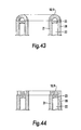
- FIGS. 42 , 43 and 44 illustrate special embodiments of magnetic field connectors for use in the third embodiment of the invention.
- FIG. 45 illustrates the third embodiment of the invention adapted for use as a transformer.
- FIGS. 46 and 47 are a section and a view of a fourth embodiment of the invention for use as a reluctance-controlled, flux-connected transformer.
- FIGS. 48 and 49 illustrate the fourth embodiment of the invention adapted to suit a powder-based magnetic material, and thereby without magnetic field connectors.
- FIGS. 50 and 51 are sections along lines VI—VI and V—V in FIG. 48 .
- FIGS. 52 and 53 illustrate a core adapted to suit a powder-based magnetic material, and thereby without magnetic field connectors.
- FIG. 54 is an “X-ray picture” of a variant of the fourth embodiment of the invention.
- FIG. 55 illustrates a second variant of the device according to the invention together with the principle behind a possibility for transformer connection.
- FIG. 56 illustrates a proposal for an electro-technical schematic symbol for the voltage connector according to the invention.
- FIG. 57 illustrates a proposal for a block schematic symbol for the voltage connector.
- FIG. 58 illustrates a magnetic circuit where the control winding and control flux are not included.
- FIGS. 59 and 60 there are proposals for electro-technical schematic symbols for the voltage converter according to the invention.
- FIG. 61 illustrates the use of the invention in an alternating current circuit.
- FIG. 62 illustrates the use of the invention in a three-phase system.
- FIG. 63 illustrates a use as a variable choke in DC—DC converters.
- FIG. 64 illustrates a use as a variable choke in a filter together with condensers.
- FIG. 65 illustrates a simplified reluctance model for the device according to the invention and a simplified electrical equivalent diagram for the connector according to the invention.
- FIG. 66 illustrates the connection for a magnetic switch.
- FIG. 67 illustrates examples of a three-phase use of the invention.
- FIG. 68 illustrates the device employed as a switch.
- FIG. 69 illustrates a circuit comprising 6 devices according to the invention.
- FIG. 70 illustrates the use of the device according to the invention as a DC-AC converter.
- FIG. 71 illustrates a use of the device according to the invention as an AC-DC converter.
- FIGS. 1 a and 1 b The invention will now be explained in principle in connection with FIGS. 1 a and 1 b.
- FIG. 1 a illustrates a device comprising a body 1 of a magnetisable material which forms a closed magnetic circuit.
- This magnetisable body or core 1 may be annular or of another suitable shape.
- Round the body 1 is wound a first main winding 2 , and the direction of the magnetic field H 1 (corresponding to the direction of the flux density B 1 ) which will be created when the main winding 2 is excited will follow the magnetic circuit.
- the main winding 2 corresponds to a winding in an ordinary transformer.
- the device includes a second main winding 3 which in the same way as the main winding 2 is wound round the magnetisable body 1 and which will thereby provide a magnetic field which extends substantially along the body 1 (i.e. parallel to H 1 , B 1 ).
- the device finally includes a third main winding 4 which in a preferred embodiment of the invention extends internally along the magnetic body 1 .
- the magnetic field H 2 (and thus the magnetic flux density B 2 ) which is created when the third main winding 4 is excited will have a direction which is at right angles to the direction of the fields in the first and the second main winding (direction of H 1 , B 1 ).
- the invention may also include a fourth main winding 5 which is wound round a leg of the body 1 . When the fourth main winding 5 is excited, it will produce a magnetic field with a direction which is at right angles both to the field in the first (H 1 ), the second and the third main winding (H 2 ) (FIG. 3 ). This will naturally require the use of a closed magnetic circuit for the field which is created by the fourth main winding. This circuit is not illustrated in the figure, since the figure is only intended to illustrate the relative positions of the windings.
- FIGS. 1 b - 1 g illustrate the definition of the axes and the direction of the different windings and the magnetic body.
- the main winding 2 will have an axis A 2 , the main winding 3 an axis A 3 and the control winding 4 an axis A 4 .
- the longitudinal direction will vary with respect to the shape. If the body is elongated, the longitudinal direction A 1 will correspond to the body's longitudinal axis. If the magnetic body is square as illustrated in FIG. 1 a , a longitudinal direction A 1 can be defined for each leg of the square. Where the body is tubular, the longitudinal direction A 1 will be the tube's axis, and for an annular body the longitudinal direction A 1 will follow the ring's circumference.
- the invention is based on the possibility of altering the characteristics of the magnetisable body 1 in relation to a first magnetic field by altering a second magnetic field which is at right angles to the first.
- the field H 1 can be defined as the working field and control the body's 1 characteristics (and thereby the behaviour of the working field H 1 ) by means of the field H 2 (hereinafter called control field H 2 ). This will now be explained in more detail.
- the magnetisation current in an electrical conductor which is enclosed by a ferromagnetic material is limited by the reluctance according to Faraday's Law.
- the flux which has to be established in order to generate counterinduced voltage depends on the reluctance in the magnetic material enclosing the conductor.
- the extent of the magnetisation current is determined by the amount of flux which has to be established in order to balance applied voltage.
- N number of turns for winding
- the magnetic induction or flux density in a magnetic material is determined by the material's relative permeability and the magnetic field intensity.
- the magnetic field intensity is generated by the current in a winding arranged round or through the material.
- N number of windings
- the ratio between magnetic induction and field intensity is non-linear, with the result that when the field intensity increases above a certain limit, the flux density will not increase and on account of a saturation phenomenon which is due to the fact that the magnetic domains in a ferromagnetic material are in a state of saturation.
- a control field H 2 which is perpendicular to a working field H 1 in the magnetic material in order to control the saturation in the magnetisable material, while avoiding magnetic connection between the two fields and thereby avoiding transformative or inductive connection.
- Transformative connection means a connection where two windings “share” a field, with the result that a change in the field from one winding will lead to a change in the field in the other winding.
- the magnetic material as a tube where the main winding or the winding which carries the working current is located inside the tube and is wound in the tube's longitudinal direction, and where the control winding or the winding which carries the control current is wound round the circumference of the tube, the desired effect is achieved.
- a small area for the control flux and a large area for the working flux are thereby also achieved.
- the working flux will travel in the direction along the tube's circumference and have a closed magnetic circuit.
- the control flux on the other hand will travel in the tube's longitudinal direction and will have to be connected in a closed magnetic circuit, either by two tubes being placed in parallel and a magnetic material connecting the control flux between the two tubes, or by a first tube being placed around a second tube, with the result that the control winding is located between the two tubes, and the end surfaces of the tubes are magnetically interconnected, thereby obtaining a closed path for the control flux.
- the parts which provide magnetic connection between the tubes or the core parts will hereinafter be called magnetic field connectors or magnetic field couplings.
- the flux density B is composed of the vector sum of B 1 and B 2 ( FIG. 4 d ).
- B 1 is generated by the current I 1 in the first main winding 2
- B 1 has a direction tangentially to the conductors in the main winding 2 .
- the main winding 2 has N 1 turns and is wound round the magnetisable body 1 .
- B 2 is generated by the current I 2 in the control winding 4 with N 2 number of turns and where the control winding 4 is wound round the body 1 .
- B 2 will have a direction tangentially to the conductors in the control winding 4 .
- the vector sum of the fields H 1 and H 2 will determine the total field in the body 1 , and thus the body's 1 condition with regard to saturation, and will be determining for the magnetisation current and the voltage which is divided between a load connected to the main winding 2 and the connector. Since the sources for B 1 and B 2 will be located orthogonally to each other, none of the fields will be able to be decomposed into the other. This means that B 1 cannot be a function of B 2 and vice versa. However, B, which is the vector sum of B 1 and B 2 will be influenced by the extent of each of them.
- the cross-sectional surface A 2 for the B 2 vector will be the transversal surface of the magnetic body 1 , cf. FIG. 4 c . This may be a small surface limited by the thickness of the magnetisable body 1 , given by the surface sector between the internal and external diameters of the body 1 , in the case of an annular body.
- the cross-sectional surface A 1 (see FIGS. 4 a, b ) for the B 1 field on the other hand is given by the length of the magnetic core and the rating of applied voltage. This surface will be able to be 5-10 times larger than the surface of the control flux density B 2 , without this being considered limiting for the invention.
- the inductance for the control winding 4 (with N 2 turns) will be able to be rated at a small value suitable for pulsed control of the regulator, i.e. enabling a rapid reaction (of the order of milliseconds) to be provided.
- N 2 Number of turns for control winding
- the magnetic field has low frequency.
- the displacement current can thus be neglected compared with the current density.
- the control winding 4 will establish a corresponding MMK generated by the current I 2 :
- the permeability in the transversal direction is of the order of 1 to 2 decades less than for the longitudinal direction.
- the capacity to conduct magnetic fields in iron is given by ⁇ r , and the magnitude of ⁇ is from 1000 to 100.000 for iron and for the new Metglas materials up to 900.000.
- the invention is based on the physical fact that the differential of the magnetic field intensity which has its source in the current in a conductor is expressed by curl to the H field.
- Curl to H says something about the differential or the field change of the H field across the field direction of H.
- the field on the basis that the surface perpendicular of the differential field loop has the same direction as the current. This means that the fields from the current-carrying conductors forming the windings which are perpendicular to each other are also orthogonal.
- the fact that the fields are perpendicular to each other is important in relation to the orientation of the domains in the material.
- the left side of the integral is an expression of the potential equation in integral form.
- the self-inductance is equal to the ratio between the flux turns established by the current in the winding (the coil) and the current in the winding (the coil).
- the self-inductance in the winding is approximately linear as long as the magnetisable body or the core are not in saturation. However, we shall change the self-inductance through changes in the permeability in the material of the magnetisable body by changing the domain magnetisation in the transversal direction by the control field (i.e. by the field H 2 which is established by the control winding 4 ).
- a transformer we employ closed cores with high permeability where energy is stored in magnetic leakage fields and a small amount in the core, but the stored energy does not form a direct part in the transformation of energy, with the result that no energy conversion takes place in the sense of what occurs in an electromechanical system where electrical energy is converted to mechanical energy, but energy is transformed via magnetic flux through the transformer.
- the reluctance in the air gap is dominant compared to the reluctance in the core, with approximately all the energy being stored in the air gap.
- a “virtual” air gap is generated through saturation phenomena in the domains.
- the energy storage will take place in a distributed air gap comprising the whole core.
- L will be varied as a function of ⁇ r, the relative permeability in the magnetisable body or the core 1 , which in turn is a function of I 2 , the control current in the control winding 4 .
- FIG. 8 and FIG. 9 The substance of what takes place is illustrated in FIG. 8 and FIG. 9 .
- FIG. 8 illustrates the magnetisation curves for the entire material of the magnetisable body 1 and the domain change under the influence of the H 1 field from the main winding 2 .
- FIG. 9 illustrates the magnetisation curves for the entire material of the magnetisable body 1 and the domain change under the influence of the H 2 field in the direction from the control winding 4 .
- FIGS. 10 a and 10 b illustrate the flux densities B 1 (where the field H 1 is established by the working current), and B 2 (corresponding to the control current).
- the ellipse illustrates the saturation limit for the B fields, i.e. when the B field reaches the limit, this will cause the material of the magnetisable body 1 to reach saturation.
- the form of the ellipse's axes will be given by the field length and the permeability of the two fields B 1 (H 1 ) and B 2 (H 2 ) in the core material of the magnetisable body 1 .
- the domain magnetisation, the inductance L and the alternating current resistance XL will thereby be varied linearly as a function of the control field B 2 .
- FIG. 11 is a schematic illustration of a second embodiment of the invention.
- FIG. 12 illustrates the same embodiment of a magnetically influenced connector according to the invention, where FIG. 12 a illustrates the assembled connector and FIG. 12 b illustrates the connector viewed from the end.
- FIG. 13 illustrates a section along line II in FIG. 12 b.
- the magnetisable body 1 is composed of inter alia two parallel tubes 6 and 7 made of magnetisable material.
- the magnetic field connectors 10 , 11 are mounted at the ends of the respective pipes 6 , 7 in order to interconnect the tubes fieldwise in a loop.
- the conductor 8 will be able to carry a load current 11 ( FIG. 12 a ).
- the tubes' 6 , 7 length and diameter will be determined on the basis of the power and voltage which have to be connected.
- the number of turns N 1 on the main winding 2 will be determined by the reverse blocking ability for voltage and the cross-sectional area of the extent of the working flux ⁇ 2 .
- the number of turns N 2 on the control winding 4 is determined by the fields required for saturation of the magnetisable body 1 , which comprises the tubes 6 , 7 and the magnetic field connectors 10 , 11 .
- FIG. 14 illustrates a special design of the main winding 2 in the device according to the invention.
- the solution in FIG. 14 differs from that illustrated in FIGS. 12 and 13 only by the fact that instead of a single insulated conductor 8 which is passed through the pipes 6 and 7 , two separate oppositely directed conductors, so-called primary conductors 8 and secondary conductors 8 ′ are employed, in order thereby to achieve a voltage converter function for the magnetically influenced device according to the invention.
- the design is basically similar to that illustrated in FIGS. 11 , 12 and 13 .
- the magnetisable body 1 comprises two parallel tubes 6 and 7 .
- At least one combined control and magnetisation winding 4 and 4 ′ is wound round the first tube 6 and the second tube 7 respectively, with the result that the field direction created on the said tube is oppositely directed.
- magnetic field connectors 10 , 11 are mounted on the end of respective tubes ( 6 , 7 ) in order to interconnect the tubes 6 and 7 fieldwise in a loop, thereby forming the magnetisable body 1 .
- FIG. 15 An embodiment of magnetic field connectors 10 and/or 11 is illustrated in FIG. 15.
- a magnetic field connector 10 , 11 is illustrated, composed of a magnetically conducting material, wherein two preferably circular apertures 12 for the conductor 8 in the main winding 2 (see, e.g. FIG. 13 ) are machined out of the magnetic material in the connectors 10 , 11 .
- a gap 13 which interrupts the magnetic field path of the conductor 8 .
- End surface 14 is the connecting surface for the magnetic field H 2 from the control winding 4 consisting of conductors 9 and 9 ′ (FIG. 13 ).
- FIG. 16 illustrates a thin insulating film 15 which will be placed between the end surface on tubes 6 and 7 and the magnetic field connector 10 , 11 in a preferred embodiment of the invention.
- FIGS. 17 and 18 illustrate other alternative embodiments of the magnetic field connectors 10 , 11 .
- FIGS. 19-32 illustrate various embodiments of a core 16 which in the embodiment illustrated in FIGS. 12 , 13 and 14 forms the main part of the tubes 6 and 7 which preferably together with the magnetic field connectors 10 and 11 form the magnetisable body 1 .
- FIG. 19 illustrates a cylindrical core part 16 which is divided lengthwise as illustrated and where there are placed one or more layers 17 of an insulating material between the two core halves 16 ′, 16 ′′.
- FIG. 20 illustrates a rectangular core part 16 and FIG. 21 illustrates an embodiment of this core part 16 where it is divided in two with partial sections in the lateral surface.
- FIG. 21 illustrates an embodiment of this core part 16 where it is divided in two with partial sections in the lateral surface.
- one or more layers of an insulating material 17 are provided between the core halves 16 , 16 ′.
- FIG. 22 illustrates a further variant where the partial section is placed in each corner.
- FIGS. 23 , 24 and 25 illustrate a rectangular shape.
- FIGS. 26 , 27 and 28 illustrate the same for a triangular shape.
- FIGS. 29 and 30 illustrate an oval variant, and finally
- FIGS. 31 and 32 illustrate a hexagonal shape.
- the hexagonal shape is composed of 6 equal surfaces 18 and in FIG. 30 the hexagon consists of two parts 16 ′ and 16 ′′.
- Reference numeral 17 refers to a thin insulating film.
- FIGS. 33 and 34 illustrate a magnetic field connector 10 , 11 which can be used as a control field connector between the rectangular and square main cores 16 (illustrated in FIGS. 20-21 and 23 - 25 respectively).
- This magnetic field connector comprises three parts 10 ′, 10 ′′ and 19 .
- FIG. 34 illustrates an embodiment of the core part or main core 16 where the end surface 14 or the connecting surface for the control flux is at right angles to the axis of the core part 16 .
- FIG. 35 illustrates a second embodiment of the core part 16 where the connecting surface 14 for the control flux is at an angle ⁇ to the axis of the core part 16 .
- FIGS. 36-38 illustrate various designs of the magnetic field connector 10 , 11 , which are based on the fact that the connecting surfaces 14 ′ of the magnetic field connector 10 , 11 are at the same angle as the end surfaces 14 to the core part 16 .
- FIG. 36 illustrates a magnetic field connector 10 , 11 in which different hole shapes 12 are indicated for the main winding 2 on the basis of the shape of the core part 16 (round, triangular, etc.).
- the magnetic connector 10 , 11 is flat. It is adapted for use with core parts 16 with right-angled end surfaces 14 .
- an angle ⁇ ′ is indicated to the magnetic field connector 10 , 11 , which is adapted to the angle ⁇ to the core part (FIG. 35 ), thus causing the end surface 14 and the connecting surface 14 ′ to coincide.
- FIG. 39 a an embodiment of the invention is illustrated with an assembly of magnetic field connectors 10 , 11 and core parts 16 .
- FIG. 39 b illustrates the same embodiment viewed from the side.
- FIGS. 40 and 41 are a sectional illustration and view respectively of a third embodiment of a magnetically influenced voltage connector device.
- the device comprises (see FIG. 40 b ) a magnetisable body 1 comprising an external tube 20 and an internal tube 21 (or core parts 16 , 16 ′) which are concentric and made of a magnetisable material with a gap 22 between the external tube's 20 inner wall and the internal tube's 21 outer wall.
- Magnetic field connectors 10 , 11 between the tubes 20 and 21 are mounted at respective ends thereof ( FIG. 40 a ).
- a spacer 23 ( FIG. 40 a ) is placed in the gap 22 , thus keeping the tubes 20 , 21 concentric.
- a combined control and magnetisation winding 4 composed of conductors 9 is wound round the internal tube 21 and is located in the said gap 22 .
- the winding axis A 2 for the control winding therefore coincides with the axis A 1 of the tubes 20 and 21 .
- FIGS. 42-44 illustrate various embodiments of the magnetic field connector 10 , 11 which are specially adapted to the latter design of the invention, i.e. as described in connection with FIGS. 40 and 41 .
- FIG. 42 a illustrates in section and FIG. 42 b in a view from above a magnetic field connector 10 , 11 with connecting surfaces 14 ′ at an angle relative to the axis of the tubes 20 , 21 (the core parts 16 ) and it is obvious that the internal 21 and external 20 tubes should also be at the same angle to the connecting surfaces 14 .
- FIGS. 43 and 44 illustrate other variants of the magnetic field connector 10 , 11 , where the connecting surfaces 14 ′ of the control field H 2 (B 2 ) are perpendicular to the main axis of the core parts 16 (tubes 20 , 21 ).
- FIG. 43 illustrates a hollow semi-toroidal magnetic field connector 10 , 11 with a hollow semi-circular cross section
- FIG. 44 illustrates a toroidal magnetic field connector with a rectangular cross section.
- FIG. 45 A variant of the device illustrated in FIGS. 40 and 41 is illustrated in FIG. 45 , where FIG. 45 a illustrates the device from the side while 45 b illustrates it from above.
- the only difference from the voltage connector in FIGS. 40-41 is that a second main winding 3 is wound in the same course as the main winding 2 .
- FIGS. 46 and 47 are a section and a view illustrating a fourth embodiment of the voltage connector with concentric tubes.
- FIGS. 46 and 47 illustrate the voltage connector which acts as a voltage converter with joined cores.
- An internal reluctance-controlled core 24 is located within an external core 25 round which is wound a main winding 2 .
- the reluctance-controlled internal core 24 has the same construction as mentioned previously under the description of FIGS. 40 and 41 , but the only difference is that there is no main winding 2 round the core 24 . It has only a control winding 4 which is located in the gap 22 between the inner 21 and outer parts forming the internal reluctance-controlled core 24 , with the result that only core 24 is magnetically reluctance-controlled under the influence of a control field H 2 (B 2 ) from current in the control winding 4 .
- H 2 control field
- the main winding 2 in FIGS. 46 and 47 is a winding which encloses both core 24 and core 25 .
- FIG. 55 illustrates the principle of the connection
- FIG. 65 with a simplified equivalent diagram for the reluctance model where Rmk is the variable reluctance which controls the flux between the windings 2 and 3
- FIG. 65 b illustrates an equivalent electrical circuit for the connection where Lk is the variable inductance.
- An alternating voltage V 1 over winding 2 will establish a magnetisation current I 1 in winding 2 .
- This is generated by the flux ⁇ 1 + ⁇ 1 ′ in the cores 24 and 25 which requires to be established in order to provide the bucking voltage which according to Faraday's Law is generated in 2 .
- the flux will be divided between the cores 24 and 25 based on the reluctance in the respective cores 24 and 25 .
- the internal reluctance-controlled core 24 has to be supplied with control current I 2 .
- the external core 25 could be made controllable, in addition to having a fourth main winding wound round the internal controllable core 24 . This is to enable the voltage between the cores 24 and 25 to be controlled as required.
- FIG. 48 describes a further variant of the fourth embodiment of a magnetically influenced voltage connector or voltage converter according to the invention, where the magnetisable body 1 is so designed that the control flux B 2 (H 2 ) is connected directly without a separate magnetic field connector through the main core 16 .
- FIG. 48 illustrates a voltage connector in the form of a toroid viewed from the side.
- the voltage connector comprises two core parts 16 and 16 ′, a main winding 2 and a control winding 4 .
- FIG. 49 illustrates a voltage connector according to the invention equipped with an extra main winding 3 which offers the possibility of converting the voltage.
- FIG. 50 illustrates the device in FIG. 48 in section along line VI—VI in FIG. 48 and FIG. 51 illustrates a section along line V—V.
- a circular aperture 12 is illustrated for placing the control winding 4 .
- FIG. 51 illustrates an additional aperture 26 for passing through wiring.
- FIGS. 52 and 53 illustrate the structure of a core 16 without windings and where the core 16 is so designed that there is no need for an extra magnetic field connector for the control field.
- the core 16 has two core parts 16 , 16 ′ and an aperture 12 for a control winding 4 .
- This design is intended for use where the magnetic material is sintered or compressed powder-moulded material. In this case it will be possible to insert closed magnetic field paths in the topology, with the result that what were previously separate connectors which were required for foil-wound cores form part of the actual core and are a productive part of the structure.
- the core which forms the closed magnetic circuit without separate magnetic field connectors and which is illustrated in these FIGS. 52 and 53 , will be able to be used in all the embodiments of the invention even though the figures illustrate a body 1 adapted for the first embodiment of the invention (illustrated inter alia in FIGS. 1 and 2 ).
- FIG. 54 illustrates a magnetically influenced voltage converter device, where the device has an internal control core 24 consisting of an external tube 20 and an internal tube 21 which are concentric and made of a magnetisable material with a gap 22 between the external tube's 20 inner wall and the internal tube's 21 outer wall. Spacers 23 are mounted in the gap between the external tube's 20 inner wall and the internal tube's 21 outer wall. Magnetic field connectors 10 , 11 are mounted between the tubes 20 and 21 at respective ends thereof. A combined control and magnetisation winding 4 is wound round the internal tube 21 and is located in the said gap 22 .
- the device further consists of an external secondary core 25 with windings comprising a plurality of ring core coils 25 ′, 25 ′′, 25 ′′′ etc.
- Each ring core coil 25 ′, 25 ′′, 25 ′′′ etc. consists of a ring of a magnetisable material wound round by a respective second main winding or secondary winding 3 , only one of which is illustrated for the sake of clarity.
- the secondary core device being located within the control core 24 , in which case the primary winding 2 will have to be passed through the ring cores 25 and along the outside of the control core 24 .
- FIG. 55 is a schematic illustration of a second embodiment of the magnetically influenced voltage regulator according to the invention with a first reluctance-controlled core 24 and a second core 25 , each of which is composed of a magnetisable material and designed in the form of a closed, magnetic circuit, the said cores being juxtaposed.
- At least one first electrical conductor 8 is wound on to a main winding 2 about both the first and the second core's cross-sectional profile along at least a part of the said closed circuit.
- At least one second electrical conductor 9 is mounted as a winding 4 in the reluctance-controlled core 24 in a form which essentially corresponds to the closed circuit.
- At least one third electrical conductor 27 is wound round the second core's 25 cross-sectional profile along at least a part of the closed circuit.
- the field direction from the first conductor's 8 winding 2 and the second conductor's 9 winding is orthogonal.
- the first conductor 8 and the third conductor 27 form a primary winding 2 and a secondary winding 3 respectively.
- FIG. 56 illustrates a proposal for an electro-technical schematic symbol for the voltage connector according to the invention.
- FIG. 57 illustrates a proposal for a block schematic symbol for the voltage connector.
- FIG. 58 illustrates a magnetic circuit where the control winding 4 and control flux B 2 (H 2 ) are not included.
- FIGS. 59 and 60 there is a proposal for an electro-technical schematic symbol for the voltage converter where the reluctance in the control core 24 shifts magnetic flux between a core with fixed reluctance 25 and a second core with variable reluctance 24 (see for example FIG. 55 ).
- the device according to the invention will be able to be used in many different connections and examples will now be given of applications in which it will be particularly suitable.
- FIG. 61 illustrates the use of the invention in an alternating current circuit in order to control the voltage over a load RL, which may be a light source, a heat source or other load.
- FIG. 62 illustrates the use of the invention in a three-phase system where such a voltage connector in each phase, connected to a diode bridge, is used for a linear regulation of the output voltage from the diode bridge.
- FIG. 63 illustrates a use as a variable choke in DC—DC converters.
- FIG. 64 illustrates a use as a variable choke in a filter together with condensers.
- a series and a parallel filter 64 a and 64 b respectively
- the variable inductance can be used in a number of filter topologies.
- a further application of the invention is that described inter alia in connection with FIGS. 14 and 45 , where proposals for schematic symbols were given in FIG. 59 .
- the voltage connector has a function as a voltage converter where a secondary winding is added.
- An application as a voltage regulator is also illustrated here, where the magnetisation current in the transformer connection and the leakage reactance are controllable via the control winding 4 .
- the special feature of this system is that the transformer equations will apply, while at the same time the magnetisation current can be controlled by changing ⁇ r. In this case, therefore, the characteristic of the transformer can be regulated to a certain extent.
- FIGS. 46 and 47 Another application of the invention is illustrated in FIGS. 46 and 47 , where a variable reluctance as control core is surrounded or enclosed by one or more separate cores with separate windings, as well as FIG. 55 where a first reluctance-controlled core and a second core are designed as closed magnetic circuits and are juxtaposed.
- FIG. 65 illustrates an equivalent electrical circuit.
- FIG. 55 illustrates how the fluxes in the invention travel in the cores.
- the flux in the control core is connected to the flux in the working core via the windings enclosing both cores.
- transformation of electrical energy will be able to be controlled by flux being connected to and disconnected from a control core and a working core. Since the fluxes between the cores are interconnected through Faraday's induction law, the functional dependence of the equations for the primary side and the equations for the secondary side will be controlled by the connection between the fluxes.
- Winding 2 which now encloses both the reluctance-controlled control core 24 and the main core 25 will establish flux in both-cores.
- the self-inductance L 1 to 2 tells how much flux, or how many flux turns are produced in the cores when a current is passed in I 1 in 2 .
- the mutual inductance between the primary winding 2 and the secondary winding 3 indicates how many of the flux turns established by 2 and I 1 are turned about 2 and about the secondary winding 3 .
- main core 25 being reluctance-controlled, but for the sake of simplicity we shall refer here to a system with a main core 25 where the reluctance is constant, and a control core 24 where the reluctance is variable.
- the flux lines will follow the path which gives the highest permanence (where the permeability is highest), i.e. with the least reluctance.
- FIG. 55 illustrates a simplified model of the transformer where the primary 2 and secondary 3 windings are each wound around a transformer leg, while in practice they will preferably be wound on the same transformer leg, and in our case, for example, the outer ring core which is the main core 25 will be wound around the secondary winding 3 distributed along the entire core 25 .
- the primary winding 2 will be wound around the main core 25 and the control core 24 which may be located concentrically and within the main core.
- FIG. 65 illustrates a simplified reluctance model for the device according to the invention.
- FIG. 65 b illustrates a simplified electrical equivalent diagram for the connector according to the invention, where the reluctances are replaced by inductances.
- ⁇ p total flux established by the current in 2 .
- ⁇ k the total flux travelling through the control core 24 .
- ⁇ 1 part of the total flux travelling through the main core 25 .
- ⁇ k may be regarded as a controlled leakage flux.
- FIG. 65 we can formulate the highly simplified electrical equivalent diagram for the magnetic circuit illustrated in FIG. 65 b.
- FIG. 65 b therefore illustrates the principle of the reluctance-controlled connector, where the inductance L k absorbs the voltage from the primary side.
- L k When the control core 24 is in saturation, L k is very small compared to L m and the voltage division will be according to the ratio between the number of turns N 1 /N 3 . When the control core is in the off state, L k will be large and to the same extent will block voltage transformation to the secondary side.
- the magnetisation of the cores relative to applied voltage and frequency is so rated that the main core 25 and the control core 24 can each separately absorb the entire time voltage integral without going into saturation.
- the area of iron on the control and working cores is equal without this being considered as limiting for the invention.
- control core 24 Since the control core 24 is not in saturation on account of the main winding 2 , we shall be able to reset the control core 24 independently of the working flux B 1 (H 1 ), thereby achieving the object by means of the invention of realising a magnetic switch. If necessary the main core 25 may be reset after an on pulse or a half on period by the necessary MMF being returned in the second half-period only in order to compensate-for any distortions in the magnetisation current.
- An important application of the invention will thus be as a frequency converter with reluctance-controlled switches and a DC-AC or AC-DC converter by employing the reluctance-controlled switch in traditional frequency converter connections and rectifier connections.
- a frequency converter variant may be envisaged realised by adding bits of sinus voltages from each phase in a three-phase system, each connected to a separate reluctance-controlled core which in turn is connected to one or more adding cores which are magnetically connected to the reluctance-controlled cores through a common winding through the adding cores and the reluctance-controlled cores. Parts of sinus voltages can then be connected from the reluctance-controlled cores into the adding core and a voltage with a different frequency is generated.
- a DC-AC converter may be realised by connecting a DC voltage to the main winding enclosing the working core, where this time the working core is also wound round a secondary winding where we can obtain a sinus voltage by changing the flux connection between working core and control core sinusoidally.
- FIG. 66 illustrates the connection for a magnetic switch. This may, of course, also act as an adjustable transformer.
- FIGS. 67 and 67 a illustrate an example of a three-phase design. All the other three-phase rectifier connectors are, of course, also feasible. By means of connection to a diode bridge or individual diodes to the respective outlets in a 12-pulse connector, an adjustable rectifier is obtained.
- the size of the reluctance-controlled core is determined by the range of adjustment which is required for the transformer, (0-100% or 80-110%) for the voltage.
- FIG. 67 b illustrates the use of the device according to the invention as a connector in a frequency converter for converting input frequency to randomly selected output frequency and intended for operation of an asynchronous motor, for adding parts of the phase voltage generated from a 6 or 12-pulse transformer to each motor phase ( FIG. 67 b ).
- FIG. 68 illustrates the device used as a switch in a UFC (unrestricted frequency changer with forced commutation).
- FIG. 69 illustrates a circuit comprising 6 devices 28 - 33 according to the invention.
- the devices 28 - 33 are employed as frequency converters where the period of the voltages generated is composed of parts of the fundamental frequency. This works by “letting through” only the positive half-periods or parts of the half-periods of a sinus voltage in order to make the positive new half-period in the new sinus voltage, and subsequently the negative half-periods or parts of the negative half-periods in order thereby to make the negative half-periods in the new sinus voltage. In this way a sinus voltage is generated with a frequency from 10% to 100% of the fundamental frequency.
- This converter also acts as a soft start since the voltage on the output is regulated via the reluctance control of the connection between the primary and the secondary winding.
- FIG. 70 illustrates the use of the device according to the invention as a DC to AC converter.
- the main winding 2 in the connector is excited by a DC voltage U 1 which establishes a field H 1 (B 1 ) both in the control core 24 and in the main core 25 (these are not shown in the figure).
- the number of turns N 1 , N 2 , N 3 and the area of iron are designed in such a manner that none of the cores are in saturation in steady state.
- a control signal i.e.
- FIG. 70 b illustrates the use of the invention as a converter with a change of reluctance.
- FIG. 71 illustrates a use of the device according to the invention as an AC-DC converter. The same control principle is used here as that explained above in the description of a frequency converter in FIG. 69 .
- FIG. 71 b illustrates a diagram of the time of the device's input and output voltage.
- the voltage connector according to the invention is substantially without movable parts for the absorption of electrical voltage between a generator and a load.
- the function of the connector is to be able to control the voltage between the generator and the load from 0-100% by means of a small control current.
- a second function will be purely as a voltage switch.
- a further function could be forming and transforming of a voltage curve.
- the new technology according to the invention will be capable of being used for upgrading existing diode rectifiers, where there is a need for regulation.
- it will be possible to balance voltages in the system in a simple manner while having controllable rectification from 0-100%.
- magnetic materials involved in the invention these will be chosen on the basis of a cost/benefit function.
- the costs will be linked to several parameters such as availability on the market, produceability for the various solutions selected, and price.
- the benefit functions are based on which electro-technical function the material requires to have, including material type and magnetic properties. Magnetic properties considered to be important include hysteresis loss, saturation flux level, permeability, magnetisation capacity in the two main directions of the material and magnetostriction.
- the electrical units frequency, voltage and power to the energy sources and users involved in the invention will be determining for the choice of material. Suitable materials include the following:
- All sintered and press-moulded cores can implement the topologies which are relevant in connection with the invention without the need for special magnetic field connectors, since the actual shape is made in such a way that closed magnetic field paths are obtained for the relevant fields.
- cores are made based on rolled sheet metal, they will have to be supplemented by one or more magnetic field connectors.
Landscapes
- Engineering & Computer Science (AREA)
- Power Engineering (AREA)
- Physics & Mathematics (AREA)
- Electromagnetism (AREA)
- General Physics & Mathematics (AREA)
- Radar, Positioning & Navigation (AREA)
- Automation & Control Theory (AREA)
- Coils Of Transformers For General Uses (AREA)
- Power Conversion In General (AREA)
Abstract
Description
1) Flux:
3) Reluctance (Flux Resistance)
∫{overscore (H)}.{overscore (ds)}=I.N
{overscore (β)}=μ0 ·μr {overscore (H)}
Φ=B·Aj 4)
{overscore (B)}={overscore (B)} 1 +{overscore (B)} 2 5)
is simplified to
curl({overscore (H)})={overscore (J)} 8)
∫({overscore (H)}){overscore (dl)}=I 9)
presents a solution for the system in
H 1 I 1 =N 1 ·I 1 11)
F 1 =N 1 ·I 1 12)
F 2 =N 2 ·I 2 14)
{overscore (B 1 )}=μ 0 ·μr 1 ·{overscore (H)} 1 15)
{overscore (B 2 )}=μ 0 ·μr 2 ·{overscore (H)} 2 16).
Φ1=∫Aj 0 {overscore (B)} 1 ·{overscore (n)}ds 19)
Φ=k·I 28)
λ=L·i+C 30)
L=N 2 /Rm 32)
XL=jwL 33)
dWelin=dWfld 34)
e=d/dtλ
e=d(L·i)/dt=L·di/dt+i·dL/dt 35)
p=i·e=i·d/dtλ 36)
dW elin =i·dλ 37)
dW elm =i·d(L·i)=i·(L·di+i·dl) 38)
Φ=Φk+Φ1 40)
where:
Φ1=−Φ2 41)
-
- a) Iron-silicon steel: produced as a strip of a thickness approximately 0.1 mm-0.3 mm and width from 10 mm to 1100 mm and rolled up into coils. Perhaps the most preferred for large cores on account of price and already developed production technology. For use at low frequencies.
- b) Iron-nickel alloys (permalloys) and/or iron-cobalt alloys (permendur) produced as a strip rolled up into coils. These are alloys with special magnetic properties with subgroups where very special properties have been cultivated.
- c) Amorphous alloys, Metglas: produced as a strip of a thickness of approximately 20 μm-50 μm, width from 4 mm to 200 mm and rolled up into coils. Very high permeability, very low loss, can be made with almost 0 magnetostriction. Exists in a countless number of variants, iron-based, cobalt-based, etc. Fantastic properties but high price.
- d) Soft ferrites: Sintered in special forms developed for the converter industry. Used at high frequencies due to small loss. Low flux density. Low loss. Restrictions on physically realisable size.
- e) Compressed powder cores: Compressed iron powder alloy in special shapes developed for special applications. Low permeability, maximum approximately 400-600 to-day. Low loss, but high flux density. Can be produced in very complicated shapes.
Claims (44)
Priority Applications (4)
| Application Number | Priority Date | Filing Date | Title |
|---|---|---|---|
| US10/278,908 US6933822B2 (en) | 2000-05-24 | 2002-10-24 | Magnetically influenced current or voltage regulator and a magnetically influenced converter |
| US10/685,345 US7026905B2 (en) | 2000-05-24 | 2003-10-14 | Magnetically controlled inductive device |
| US11/033,483 US7193495B2 (en) | 2000-05-24 | 2005-01-11 | Magnetically influenced current or voltage regulator and a magnetically influenced converter |
| US11/347,483 US7256678B2 (en) | 2000-05-24 | 2006-02-03 | Magnetically controlled inductive device |
Applications Claiming Priority (5)
| Application Number | Priority Date | Filing Date | Title |
|---|---|---|---|
| NO20002652 | 2000-05-24 | ||
| NO20002652A NO317045B1 (en) | 2000-05-24 | 2000-05-24 | Magnetically adjustable current or voltage regulating device |
| PCT/NO2001/000217 WO2001090835A1 (en) | 2000-05-24 | 2001-05-23 | Magnetic controlled current or voltage regulator and transformer |
| US33056201P | 2001-10-25 | 2001-10-25 | |
| US10/278,908 US6933822B2 (en) | 2000-05-24 | 2002-10-24 | Magnetically influenced current or voltage regulator and a magnetically influenced converter |
Related Parent Applications (1)
| Application Number | Title | Priority Date | Filing Date |
|---|---|---|---|
| PCT/NO2001/000217 Continuation WO2001090835A1 (en) | 2000-05-24 | 2001-05-23 | Magnetic controlled current or voltage regulator and transformer |
Related Child Applications (2)
| Application Number | Title | Priority Date | Filing Date |
|---|---|---|---|
| US10/685,345 Continuation-In-Part US7026905B2 (en) | 2000-05-24 | 2003-10-14 | Magnetically controlled inductive device |
| US11/033,483 Division US7193495B2 (en) | 2000-05-24 | 2005-01-11 | Magnetically influenced current or voltage regulator and a magnetically influenced converter |
Publications (2)
| Publication Number | Publication Date |
|---|---|
| US20030076202A1 US20030076202A1 (en) | 2003-04-24 |
| US6933822B2 true US6933822B2 (en) | 2005-08-23 |
Family
ID=27353355
Family Applications (2)
| Application Number | Title | Priority Date | Filing Date |
|---|---|---|---|
| US10/278,908 Expired - Fee Related US6933822B2 (en) | 2000-05-24 | 2002-10-24 | Magnetically influenced current or voltage regulator and a magnetically influenced converter |
| US11/033,483 Expired - Fee Related US7193495B2 (en) | 2000-05-24 | 2005-01-11 | Magnetically influenced current or voltage regulator and a magnetically influenced converter |
Family Applications After (1)
| Application Number | Title | Priority Date | Filing Date |
|---|---|---|---|
| US11/033,483 Expired - Fee Related US7193495B2 (en) | 2000-05-24 | 2005-01-11 | Magnetically influenced current or voltage regulator and a magnetically influenced converter |
Country Status (1)
| Country | Link |
|---|---|
| US (2) | US6933822B2 (en) |
Cited By (23)
| Publication number | Priority date | Publication date | Assignee | Title |
|---|---|---|---|---|
| US20030025416A1 (en) * | 1997-10-16 | 2003-02-06 | Sullivan Steven L. | Generators and transformers with toroidally wound stator winding |
| US20050043765A1 (en) * | 2003-06-04 | 2005-02-24 | Williams Michael S. | Intravascular electrophysiological system and methods |
| US20060097711A1 (en) * | 2004-11-09 | 2006-05-11 | Brandt Randy L | DC-DC converter having magnetic feedback |
| US20060224225A1 (en) * | 2003-06-04 | 2006-10-05 | Terrance Ransbury | Implantable intravascular device for defibrillation and/or pacing |
| US7117898B1 (en) * | 1998-12-03 | 2006-10-10 | Michel Van De Wiele Nv Carpet And Velvet Machinery | Guide rods for a Jacquard loom |
| WO2008003006A2 (en) * | 2006-06-29 | 2008-01-03 | Intel Corporation | Configurable multiphase coupled magnetic structure |
| US20090036939A1 (en) * | 2007-08-02 | 2009-02-05 | Udai Singh | Inductive element for intravascular implantable devices |
| US20090070308A1 (en) * | 2007-08-31 | 2009-03-12 | Powerset, Inc. | Checkpointing Iterators During Search |
| US7747335B2 (en) | 2003-12-12 | 2010-06-29 | Synecor Llc | Implantable medical device having pre-implant exoskeleton |
| US20100164668A1 (en) * | 2007-02-20 | 2010-07-01 | Hexaformer Ab | Reactor Core |
| US7840282B2 (en) | 2003-06-04 | 2010-11-23 | Synecor Llc | Method and apparatus for retaining medical implants within body vessels |
| US20110050004A1 (en) * | 2008-04-11 | 2011-03-03 | Magtech As | Power transmission system |
| US20110050382A1 (en) * | 2009-08-25 | 2011-03-03 | Access Business Group International Llc | Flux concentrator and method of making a magnetic flux concentrator |
| US20110089767A1 (en) * | 2008-03-17 | 2011-04-21 | Vetco Gray Scandinavia As | Arrangement related to offshore cable system |
| WO2011073771A1 (en) * | 2009-12-18 | 2011-06-23 | Vetco Gray Scandinavia As | Transformer |
| US8239045B2 (en) | 2003-06-04 | 2012-08-07 | Synecor Llc | Device and method for retaining a medical device within a vessel |
| EP2535783A1 (en) | 2011-06-16 | 2012-12-19 | Vetco Gray Scandinavia AS | Transformer |
| US8421368B2 (en) | 2007-07-31 | 2013-04-16 | Lsi Industries, Inc. | Control of light intensity using pulses of a fixed duration and frequency |
| US8497203B2 (en) | 2010-08-13 | 2013-07-30 | International Business Machines Corporation | Semiconductor structures and methods of manufacture |
| US8604709B2 (en) | 2007-07-31 | 2013-12-10 | Lsi Industries, Inc. | Methods and systems for controlling electrical power to DC loads |
| US8903577B2 (en) | 2009-10-30 | 2014-12-02 | Lsi Industries, Inc. | Traction system for electrically powered vehicles |
| NO339867B1 (en) * | 2008-04-11 | 2017-02-13 | Magtech As | Energy Transfer System |
| US20220255416A1 (en) * | 2021-02-08 | 2022-08-11 | Delta Electronics, Inc. | Soft-switching power converter |
Families Citing this family (15)
| Publication number | Priority date | Publication date | Assignee | Title |
|---|---|---|---|---|
| KR100626055B1 (en) * | 2005-01-10 | 2006-09-21 | 삼성에스디아이 주식회사 | Drive of display panel |
| CH697642B1 (en) * | 2007-05-15 | 2008-12-31 | Philippe Saint Ger Ag | Magnetic coupling influencing method for e.g. permanent magnet, involves displacing magnetic field present between bodies out of field displacement area of field displacement device in prescribed manner by corresponding actuation of device |
| WO2009090657A2 (en) * | 2008-01-20 | 2009-07-23 | Minicom Advanced Systems Ltd. | Controllable power relay |
| US8178998B2 (en) * | 2009-06-30 | 2012-05-15 | Verde Power Supply | Magnetically integrated current reactor |
| FR2972865B1 (en) * | 2011-03-18 | 2013-04-12 | Electricite De France | ELECTRONIC SERIES VOLTAGE REGULATOR PROTECTED FROM SHORT CIRCUITS BY MAGNETIC CIRCUIT DENYAGE WITH HOLES AND WINDOWS |
| US9245675B2 (en) * | 2013-11-18 | 2016-01-26 | National Synchrotron Radiation Research Center | Generating apparatus of a pulsed magnetic field |
| CA2982563A1 (en) | 2015-05-15 | 2016-11-24 | Halliburton Energy Services, Inc. | Geometrically configurable multi-core inductor and methods for tools having particular space constraints |
| US10373755B2 (en) | 2015-11-30 | 2019-08-06 | Eagle Harbor Technologies, Inc. | High voltage transformer |
| US9979273B2 (en) | 2016-05-19 | 2018-05-22 | Abb Schweiz Ag | Resonant converters with variable inductor |
| BR112018068494A2 (en) | 2016-08-05 | 2019-01-22 | Faraday Grid Ltd | system and process of electric power supply |
| JP2019528031A (en) | 2016-09-14 | 2019-10-03 | ファラデー グリッド リミテッドFaraday Grid Limited | Power distribution network and processing method |
| US11387741B2 (en) * | 2017-03-28 | 2022-07-12 | Allison Naito | Superconducting magnet engine |
| EP3413322A1 (en) * | 2017-06-08 | 2018-12-12 | Goodrich Control Systems | Active inductor |
| EP3563934B1 (en) | 2018-04-30 | 2021-08-25 | NOV Process & Flow Technologies AS | Method for controlling the power supply to electrodes of an coalescer |
| EP3723254A1 (en) * | 2019-04-10 | 2020-10-14 | Siemens Aktiengesellschaft | Circuit assembly, electrolysis device and method for operating a circuit or an electrolysis device |
Citations (36)
| Publication number | Priority date | Publication date | Assignee | Title |
|---|---|---|---|---|
| US2284406A (en) | 1940-03-01 | 1942-05-26 | Gen Electric | Transformer |
| US2333015A (en) | 1939-11-28 | 1943-10-26 | Gen Electric | Variable reactance device |
| US2716736A (en) | 1949-12-08 | 1955-08-30 | Harold B Rex | Saturable reactor |
| US2825869A (en) | 1955-04-07 | 1958-03-04 | Sperry Rand Corp | Bi-toroidal transverse magnetic amplifier with core structure providing highest symmetry and a closed magnetic path |
| US3409822A (en) | 1965-12-14 | 1968-11-05 | Wanlass Electric Company | Voltage regulator |
| US3612988A (en) | 1969-09-15 | 1971-10-12 | Wanlass Cravens Lamar | Flux-gated voltage regulator |
| US3757201A (en) | 1972-05-19 | 1973-09-04 | L Cornwell | Electric power controlling or regulating system |
| SU441601A1 (en) | 1971-09-23 | 1974-08-30 | Государственный Научно-Исследовательский Энергетический Институт Им.Г.М.Кржижановского | Electric reactor |
| US4002999A (en) | 1975-11-03 | 1977-01-11 | General Electric Company | Static inverter with controlled core saturation |
| US4004251A (en) | 1975-11-03 | 1977-01-18 | General Electric Company | Inverter transformer |
| US4020440A (en) | 1975-11-25 | 1977-04-26 | Moerman Nathan A | Conversion and control of electrical energy by electromagnetic induction |
| FR2344109A1 (en) | 1976-03-08 | 1977-10-07 | Ungari Serge | Transformer with laminated cylindrical core - has central core carrying windings and encircled by laminated outer core |
| US4163189A (en) | 1976-06-04 | 1979-07-31 | Siemens Aktiengesellschaft | Transformer with a ferromagnetic core for d-c and a-c signals |
| US4202031A (en) | 1978-11-01 | 1980-05-06 | General Electric Company | Static inverter employing an assymetrically energized inductor |
| US4210859A (en) * | 1978-04-18 | 1980-07-01 | Technion Research & Development Foundation Ltd. | Inductive device having orthogonal windings |
| EP0018296A1 (en) | 1979-04-23 | 1980-10-29 | Serge Ungari | Coil or trellis utilisable in variable transformers, adjustable power or precision resistors, coding resistors, wound resistors, electric radiators and heat exchangers |
| SU877631A1 (en) | 1980-02-29 | 1981-10-30 | Предприятие П/Я М-5075 | Controlled transformer |
| US4308495A (en) | 1979-04-20 | 1981-12-29 | Sony Corporation | Transformer for voltage regulators |
| US4393157A (en) | 1978-10-20 | 1983-07-12 | Hydro Quebec | Variable inductor |
| JPS6423105A (en) | 1987-07-17 | 1989-01-25 | Japan Aviation Electron | Film thickness evaluating device |
| WO1994011891A1 (en) | 1992-11-09 | 1994-05-26 | Asea Brown Boveri Ab | Controllable inductor |
| US5404101A (en) | 1992-02-27 | 1995-04-04 | Logue; Delmar L. | Rotary sensing device utilizing a rotating magnetic field within a hollow toroid core |
| JPH07201587A (en) | 1993-12-28 | 1995-08-04 | Hitachi Ferrite Denshi Kk | Pulse transformer for isdn |
| JPH07201590A (en) | 1993-12-28 | 1995-08-04 | Hitachi Ferrite Denshi Kk | Pulse transformer for isdn |
| JPH07201588A (en) | 1993-12-28 | 1995-08-04 | Hitachi Ferrite Denshi Kk | Pulse transformer for isdn |
| WO1997034210A1 (en) | 1996-03-15 | 1997-09-18 | Abb Research Ltd. | Controllable reactor with feedback control winding |
| US5672967A (en) | 1995-09-19 | 1997-09-30 | Southwest Research Institute | Compact tri-axial fluxgate magnetometer and housing with unitary orthogonal sensor substrate |
| WO1998031024A1 (en) | 1997-01-08 | 1998-07-16 | Asea Brown Boveri Ab | A controllable inductor |
| RU2125310C1 (en) | 1996-06-18 | 1999-01-20 | Сюксин Эспер Аркадьевич | High-frequency transformer |
| US5936503A (en) | 1997-02-14 | 1999-08-10 | Asea Brown Boveri Ab | Controllable inductor |
| US6232865B1 (en) | 1997-03-26 | 2001-05-15 | Asea Brown Boveri Ab | Core for a controllable inductor and a method for producing therof |
| GB2361107A (en) | 2000-04-03 | 2001-10-10 | Abb Ab | Magnetic bias of a magnetic core portion used to adjust a core's reluctance |
| US6307468B1 (en) | 1999-07-20 | 2001-10-23 | Avid Identification Systems, Inc. | Impedance matching network and multidimensional electromagnetic field coil for a transponder interrogator |
| DE10062091C1 (en) | 2000-12-13 | 2002-07-11 | Urs Graubner | Inductive component for power or communications applications has 2 complementary shell cores with ferromagnetic wire sections in ring around core axis |
| WO2002059918A1 (en) | 2001-01-23 | 2002-08-01 | Buswell Harrie R | Wire core inductive devices having a flux coupling structure and methods of making the same |
| US6429765B1 (en) | 1996-05-23 | 2002-08-06 | Abb Ab | Controllable inductor |
Family Cites Families (4)
| Publication number | Priority date | Publication date | Assignee | Title |
|---|---|---|---|---|
| US2232105A (en) | 1936-06-04 | 1941-02-18 | Twin Coach Co | Vehicle driving construction and arrangement |
| JPH01231305A (en) | 1988-03-11 | 1989-09-14 | Hitachi Ltd | Foil-wound transformer |
| US5627967A (en) | 1991-09-24 | 1997-05-06 | International Business Machines Corporation | Automated generation on file access control system commands in a data processing system with front end processing of a master list |
| US5684678A (en) * | 1995-12-08 | 1997-11-04 | Delco Electronics Corp. | Resonant converter with controlled inductor |
-
2002
- 2002-10-24 US US10/278,908 patent/US6933822B2/en not_active Expired - Fee Related
-
2005
- 2005-01-11 US US11/033,483 patent/US7193495B2/en not_active Expired - Fee Related
Patent Citations (36)
| Publication number | Priority date | Publication date | Assignee | Title |
|---|---|---|---|---|
| US2333015A (en) | 1939-11-28 | 1943-10-26 | Gen Electric | Variable reactance device |
| US2284406A (en) | 1940-03-01 | 1942-05-26 | Gen Electric | Transformer |
| US2716736A (en) | 1949-12-08 | 1955-08-30 | Harold B Rex | Saturable reactor |
| US2825869A (en) | 1955-04-07 | 1958-03-04 | Sperry Rand Corp | Bi-toroidal transverse magnetic amplifier with core structure providing highest symmetry and a closed magnetic path |
| US3409822A (en) | 1965-12-14 | 1968-11-05 | Wanlass Electric Company | Voltage regulator |
| US3612988A (en) | 1969-09-15 | 1971-10-12 | Wanlass Cravens Lamar | Flux-gated voltage regulator |
| SU441601A1 (en) | 1971-09-23 | 1974-08-30 | Государственный Научно-Исследовательский Энергетический Институт Им.Г.М.Кржижановского | Electric reactor |
| US3757201A (en) | 1972-05-19 | 1973-09-04 | L Cornwell | Electric power controlling or regulating system |
| US4002999A (en) | 1975-11-03 | 1977-01-11 | General Electric Company | Static inverter with controlled core saturation |
| US4004251A (en) | 1975-11-03 | 1977-01-18 | General Electric Company | Inverter transformer |
| US4020440A (en) | 1975-11-25 | 1977-04-26 | Moerman Nathan A | Conversion and control of electrical energy by electromagnetic induction |
| FR2344109A1 (en) | 1976-03-08 | 1977-10-07 | Ungari Serge | Transformer with laminated cylindrical core - has central core carrying windings and encircled by laminated outer core |
| US4163189A (en) | 1976-06-04 | 1979-07-31 | Siemens Aktiengesellschaft | Transformer with a ferromagnetic core for d-c and a-c signals |
| US4210859A (en) * | 1978-04-18 | 1980-07-01 | Technion Research & Development Foundation Ltd. | Inductive device having orthogonal windings |
| US4393157A (en) | 1978-10-20 | 1983-07-12 | Hydro Quebec | Variable inductor |
| US4202031A (en) | 1978-11-01 | 1980-05-06 | General Electric Company | Static inverter employing an assymetrically energized inductor |
| US4308495A (en) | 1979-04-20 | 1981-12-29 | Sony Corporation | Transformer for voltage regulators |
| EP0018296A1 (en) | 1979-04-23 | 1980-10-29 | Serge Ungari | Coil or trellis utilisable in variable transformers, adjustable power or precision resistors, coding resistors, wound resistors, electric radiators and heat exchangers |
| SU877631A1 (en) | 1980-02-29 | 1981-10-30 | Предприятие П/Я М-5075 | Controlled transformer |
| JPS6423105A (en) | 1987-07-17 | 1989-01-25 | Japan Aviation Electron | Film thickness evaluating device |
| US5404101A (en) | 1992-02-27 | 1995-04-04 | Logue; Delmar L. | Rotary sensing device utilizing a rotating magnetic field within a hollow toroid core |
| WO1994011891A1 (en) | 1992-11-09 | 1994-05-26 | Asea Brown Boveri Ab | Controllable inductor |
| JPH07201587A (en) | 1993-12-28 | 1995-08-04 | Hitachi Ferrite Denshi Kk | Pulse transformer for isdn |
| JPH07201590A (en) | 1993-12-28 | 1995-08-04 | Hitachi Ferrite Denshi Kk | Pulse transformer for isdn |
| JPH07201588A (en) | 1993-12-28 | 1995-08-04 | Hitachi Ferrite Denshi Kk | Pulse transformer for isdn |
| US5672967A (en) | 1995-09-19 | 1997-09-30 | Southwest Research Institute | Compact tri-axial fluxgate magnetometer and housing with unitary orthogonal sensor substrate |
| WO1997034210A1 (en) | 1996-03-15 | 1997-09-18 | Abb Research Ltd. | Controllable reactor with feedback control winding |
| US6429765B1 (en) | 1996-05-23 | 2002-08-06 | Abb Ab | Controllable inductor |
| RU2125310C1 (en) | 1996-06-18 | 1999-01-20 | Сюксин Эспер Аркадьевич | High-frequency transformer |
| WO1998031024A1 (en) | 1997-01-08 | 1998-07-16 | Asea Brown Boveri Ab | A controllable inductor |
| US5936503A (en) | 1997-02-14 | 1999-08-10 | Asea Brown Boveri Ab | Controllable inductor |
| US6232865B1 (en) | 1997-03-26 | 2001-05-15 | Asea Brown Boveri Ab | Core for a controllable inductor and a method for producing therof |
| US6307468B1 (en) | 1999-07-20 | 2001-10-23 | Avid Identification Systems, Inc. | Impedance matching network and multidimensional electromagnetic field coil for a transponder interrogator |
| GB2361107A (en) | 2000-04-03 | 2001-10-10 | Abb Ab | Magnetic bias of a magnetic core portion used to adjust a core's reluctance |
| DE10062091C1 (en) | 2000-12-13 | 2002-07-11 | Urs Graubner | Inductive component for power or communications applications has 2 complementary shell cores with ferromagnetic wire sections in ring around core axis |
| WO2002059918A1 (en) | 2001-01-23 | 2002-08-01 | Buswell Harrie R | Wire core inductive devices having a flux coupling structure and methods of making the same |
Non-Patent Citations (13)
| Title |
|---|
| Fiorillo et al., "Comprehensive Model of Magnetization Curve, Hysteresis Loops, and Losses in Any Direction in Grain-Oriented Fe-Si." IEEE Transactions of Magnetics, vol. 38, No. 3 (May 2002), pp. 1467-1476. |
| Great Britain Search Report Mailing Date Feb. 26, 2004. |
| Hubert et al. Magnetic Domains: the Analysis of Magnetic Microstructures, pp. 416-417 and pp. 532-533. |
| International Preliminary Examination Report, PCT/NO 02/00434, Mailing Date Mar. 16, 2004. |
| International Preliminary Examination Report, PCT/NO 02/00435, Mailing Date Mar. 16, 2004. |
| International Search Report PCT/NO 02/00004 Mailing Date May 16, 2003. |
| International Search Report PCT/NO 02/00435 Mailing Date Mar. 6, 2003. |
| International Search Report, PCT/NO 02/00434, Mailing Date Mar. 4, 2003. |
| Norwegian Search Report 2002 5268 Mailing Date Jun. 30, 2003. |
| Norwegian Search Report, 2000 2652, Mailing Date Apr. 30, 2002. |
| Norwegian Search Report, 2001 5689, Mailing Date Jul. 10, 2002. |
| PCT Search Report PCT/NO 03/00417 Mailing Date Apr. 13, 2004. |
| PCT Written Opinion PCT/NO 03/00417, Mailing Date Sep. 9, 2004. |
Cited By (40)
| Publication number | Priority date | Publication date | Assignee | Title |
|---|---|---|---|---|
| US20030025416A1 (en) * | 1997-10-16 | 2003-02-06 | Sullivan Steven L. | Generators and transformers with toroidally wound stator winding |
| US7538524B2 (en) * | 1997-10-16 | 2009-05-26 | Omnidyne, Inc. | Generators and transformers with toroidally wound stator winding |
| US7117898B1 (en) * | 1998-12-03 | 2006-10-10 | Michel Van De Wiele Nv Carpet And Velvet Machinery | Guide rods for a Jacquard loom |
| US7734343B2 (en) | 2003-06-04 | 2010-06-08 | Synecor, Llc | Implantable intravascular device for defibrillation and/or pacing |
| US20050043765A1 (en) * | 2003-06-04 | 2005-02-24 | Williams Michael S. | Intravascular electrophysiological system and methods |
| US20060224225A1 (en) * | 2003-06-04 | 2006-10-05 | Terrance Ransbury | Implantable intravascular device for defibrillation and/or pacing |
| US8239045B2 (en) | 2003-06-04 | 2012-08-07 | Synecor Llc | Device and method for retaining a medical device within a vessel |
| US7899554B2 (en) | 2003-06-04 | 2011-03-01 | Synecor Llc | Intravascular System and Method |
| US7840282B2 (en) | 2003-06-04 | 2010-11-23 | Synecor Llc | Method and apparatus for retaining medical implants within body vessels |
| US7747335B2 (en) | 2003-12-12 | 2010-06-29 | Synecor Llc | Implantable medical device having pre-implant exoskeleton |
| US20060097711A1 (en) * | 2004-11-09 | 2006-05-11 | Brandt Randy L | DC-DC converter having magnetic feedback |
| US7378828B2 (en) * | 2004-11-09 | 2008-05-27 | The Boeing Company | DC-DC converter having magnetic feedback |
| US20080001693A1 (en) * | 2006-06-29 | 2008-01-03 | Jae-Hong Hahn | Configurable multiphase coupled magnetic structure |
| US7733204B2 (en) | 2006-06-29 | 2010-06-08 | Intel Corporation | Configurable multiphase coupled magnetic structure |
| WO2008003006A3 (en) * | 2006-06-29 | 2008-02-21 | Intel Corp | Configurable multiphase coupled magnetic structure |
| WO2008003006A2 (en) * | 2006-06-29 | 2008-01-03 | Intel Corporation | Configurable multiphase coupled magnetic structure |
| CN101479817B (en) * | 2006-06-29 | 2012-07-18 | 英特尔公司 | Configurable multiphase coupled magnetic structure |
| US20100164668A1 (en) * | 2007-02-20 | 2010-07-01 | Hexaformer Ab | Reactor Core |
| US8604709B2 (en) | 2007-07-31 | 2013-12-10 | Lsi Industries, Inc. | Methods and systems for controlling electrical power to DC loads |
| US8421368B2 (en) | 2007-07-31 | 2013-04-16 | Lsi Industries, Inc. | Control of light intensity using pulses of a fixed duration and frequency |
| US20090036939A1 (en) * | 2007-08-02 | 2009-02-05 | Udai Singh | Inductive element for intravascular implantable devices |
| US8335571B2 (en) | 2007-08-02 | 2012-12-18 | Synecor, Llc. | Inductive element for intravascular implantable devices |
| US8060218B2 (en) | 2007-08-02 | 2011-11-15 | Synecor, Llc | Inductive element for intravascular implantable devices |
| US20090070308A1 (en) * | 2007-08-31 | 2009-03-12 | Powerset, Inc. | Checkpointing Iterators During Search |
| US20110089767A1 (en) * | 2008-03-17 | 2011-04-21 | Vetco Gray Scandinavia As | Arrangement related to offshore cable system |
| US8558416B2 (en) * | 2008-04-11 | 2013-10-15 | Magtech As | Power transmission system |
| NO339867B1 (en) * | 2008-04-11 | 2017-02-13 | Magtech As | Energy Transfer System |
| US20110050004A1 (en) * | 2008-04-11 | 2011-03-03 | Magtech As | Power transmission system |
| US20110050382A1 (en) * | 2009-08-25 | 2011-03-03 | Access Business Group International Llc | Flux concentrator and method of making a magnetic flux concentrator |
| US8692639B2 (en) | 2009-08-25 | 2014-04-08 | Access Business Group International Llc | Flux concentrator and method of making a magnetic flux concentrator |
| US8903577B2 (en) | 2009-10-30 | 2014-12-02 | Lsi Industries, Inc. | Traction system for electrically powered vehicles |
| EP2513924A1 (en) * | 2009-12-18 | 2012-10-24 | Vetco Gray Scandinavia AS | Transformer |
| EP2513924A4 (en) * | 2009-12-18 | 2014-03-05 | Vetco Gray Scandinavia As | Transformer |
| WO2011073771A1 (en) * | 2009-12-18 | 2011-06-23 | Vetco Gray Scandinavia As | Transformer |
| US8497203B2 (en) | 2010-08-13 | 2013-07-30 | International Business Machines Corporation | Semiconductor structures and methods of manufacture |
| EP2535783A1 (en) | 2011-06-16 | 2012-12-19 | Vetco Gray Scandinavia AS | Transformer |
| US20220255416A1 (en) * | 2021-02-08 | 2022-08-11 | Delta Electronics, Inc. | Soft-switching power converter |
| US11967898B2 (en) * | 2021-02-08 | 2024-04-23 | Delta Electronics, Inc. | Soft-switching power converter |
| US20240154517A1 (en) * | 2021-02-08 | 2024-05-09 | Delta Electronics, Inc. | Soft-switching power converter |
| US12132400B2 (en) * | 2021-02-08 | 2024-10-29 | Delta Electronics, Inc. | Soft-switching power converter |
Also Published As
| Publication number | Publication date |
|---|---|
| US20050190585A1 (en) | 2005-09-01 |
| US20030076202A1 (en) | 2003-04-24 |
| US7193495B2 (en) | 2007-03-20 |
Similar Documents
| Publication | Publication Date | Title |
|---|---|---|
| US6933822B2 (en) | Magnetically influenced current or voltage regulator and a magnetically influenced converter | |
| EP1303800B1 (en) | Magnetic controlled current or voltage regulator and transformer | |
| US7256678B2 (en) | Magnetically controlled inductive device | |
| Kheraluwala et al. | Performance characterization of a high-power dual active bridge DC-to-DC converter | |
| Barnard et al. | Sliding transformers for linear contactless power delivery | |
| US7277302B2 (en) | 12-pulse converter including a filter choke incorporated in the rectifier | |
| El Shafei et al. | Development of a medium voltage, high power, high frequency four-port solid state transformer | |
| US5789907A (en) | Variable impedence transformer | |
| CN101669275B (en) | Device and method for generating a direct voltage or a direct current | |
| US7474188B2 (en) | 40° phase-shifting autotransformer | |
| Chen et al. | Asymmetrical winding configuration to reduce inrush current with appropriate short-circuit current in transformer | |
| CA2344815C (en) | Permanent magnetic core device | |
| Ratanapanachote | Applications of an electronic transformer in a power distribution system | |
| CN112992510A (en) | Self-excitation type three-phase three-column type electrically-controlled reactor | |
| CN111755232A (en) | A wide-range multi-gear adjustable buck-boost user transformer | |
| CN211828422U (en) | Self-coupling transformer and body structure thereof | |
| CN103262402A (en) | A method for increasing power transferred by an integrated inductor and a resonant-ode power supply with an integrated inductor | |
| CN112865127A (en) | Dynamic reactive power compensation device | |
| Yuan et al. | Coupled autotransformer and magnetic‐control soft‐start method for super‐large‐capacity high‐voltage motors | |
| Tamada et al. | A proposal of modular multilevel converter using a three-winding transformer | |
| CN112750603A (en) | Voltage regulating method of high-voltage side of autotransformer, transformer body structure and autotransformer | |
| CN215682151U (en) | Multiphase flow energy transmission rectifier | |
| Liang et al. | Transformer winding connections for practical industrial applications | |
| TW202211266A (en) | Multi-phase voltage transforming device capable of generating special phase angles | |
| Leung | Design considerations of high voltage and high frequency 3 phase transformer for solid state transformer application |
Legal Events
| Date | Code | Title | Description |
|---|---|---|---|
| AS | Assignment |
Owner name: MAGTECH AS, NORWAY Free format text: ASSIGNMENT OF ASSIGNORS INTEREST;ASSIGNORS:HAUGS, ESPEN;STRAND, FRANK;REEL/FRAME:013588/0905 Effective date: 20021118 |
|
| FEPP | Fee payment procedure |
Free format text: PAYOR NUMBER ASSIGNED (ORIGINAL EVENT CODE: ASPN); ENTITY STATUS OF PATENT OWNER: SMALL ENTITY |
|
| FPAY | Fee payment |
Year of fee payment: 4 |
|
| FPAY | Fee payment |
Year of fee payment: 8 |
|
| AS | Assignment |
Owner name: AKER PROCESS SYSTEMS AS, NORWAY Free format text: LICENSE;ASSIGNOR:MAGTECH AS;REEL/FRAME:033710/0972 Effective date: 20140908 |
|
| REMI | Maintenance fee reminder mailed | ||
| LAPS | Lapse for failure to pay maintenance fees |
Free format text: PATENT EXPIRED FOR FAILURE TO PAY MAINTENANCE FEES (ORIGINAL EVENT CODE: EXP.) |
|
| STCH | Information on status: patent discontinuation |
Free format text: PATENT EXPIRED DUE TO NONPAYMENT OF MAINTENANCE FEES UNDER 37 CFR 1.362 |
|
| FP | Lapsed due to failure to pay maintenance fee |
Effective date: 20170823 |