US6840656B2 - Light guiding plate for backlight module - Google Patents
Light guiding plate for backlight module Download PDFInfo
- Publication number
- US6840656B2 US6840656B2 US10/377,420 US37742003A US6840656B2 US 6840656 B2 US6840656 B2 US 6840656B2 US 37742003 A US37742003 A US 37742003A US 6840656 B2 US6840656 B2 US 6840656B2
- Authority
- US
- United States
- Prior art keywords
- light
- guiding plate
- light guiding
- backlight module
- illumination element
- Prior art date
- Legal status (The legal status is an assumption and is not a legal conclusion. Google has not performed a legal analysis and makes no representation as to the accuracy of the status listed.)
- Expired - Fee Related
Links
Images


Classifications
-
- G—PHYSICS
- G09—EDUCATION; CRYPTOGRAPHY; DISPLAY; ADVERTISING; SEALS
- G09F—DISPLAYING; ADVERTISING; SIGNS; LABELS OR NAME-PLATES; SEALS
- G09F13/00—Illuminated signs; Luminous advertising
- G09F13/04—Signs, boards or panels, illuminated from behind the insignia
- G09F13/0409—Arrangements for homogeneous illumination of the display surface, e.g. using a layer having a non-uniform transparency
-
- F—MECHANICAL ENGINEERING; LIGHTING; HEATING; WEAPONS; BLASTING
- F21—LIGHTING
- F21V—FUNCTIONAL FEATURES OR DETAILS OF LIGHTING DEVICES OR SYSTEMS THEREOF; STRUCTURAL COMBINATIONS OF LIGHTING DEVICES WITH OTHER ARTICLES, NOT OTHERWISE PROVIDED FOR
- F21V3/00—Globes; Bowls; Cover glasses
-
- G—PHYSICS
- G02—OPTICS
- G02F—OPTICAL DEVICES OR ARRANGEMENTS FOR THE CONTROL OF LIGHT BY MODIFICATION OF THE OPTICAL PROPERTIES OF THE MEDIA OF THE ELEMENTS INVOLVED THEREIN; NON-LINEAR OPTICS; FREQUENCY-CHANGING OF LIGHT; OPTICAL LOGIC ELEMENTS; OPTICAL ANALOGUE/DIGITAL CONVERTERS
- G02F1/00—Devices or arrangements for the control of the intensity, colour, phase, polarisation or direction of light arriving from an independent light source, e.g. switching, gating or modulating; Non-linear optics
- G02F1/01—Devices or arrangements for the control of the intensity, colour, phase, polarisation or direction of light arriving from an independent light source, e.g. switching, gating or modulating; Non-linear optics for the control of the intensity, phase, polarisation or colour
- G02F1/13—Devices or arrangements for the control of the intensity, colour, phase, polarisation or direction of light arriving from an independent light source, e.g. switching, gating or modulating; Non-linear optics for the control of the intensity, phase, polarisation or colour based on liquid crystals, e.g. single liquid crystal display cells
- G02F1/133—Constructional arrangements; Operation of liquid crystal cells; Circuit arrangements
- G02F1/1333—Constructional arrangements; Manufacturing methods
- G02F1/1335—Structural association of cells with optical devices, e.g. polarisers or reflectors
- G02F1/1336—Illuminating devices
- G02F1/133602—Direct backlight
- G02F1/133606—Direct backlight including a specially adapted diffusing, scattering or light controlling members
-
- H—ELECTRICITY
- H04—ELECTRIC COMMUNICATION TECHNIQUE
- H04N—PICTORIAL COMMUNICATION, e.g. TELEVISION
- H04N1/00—Scanning, transmission or reproduction of documents or the like, e.g. facsimile transmission; Details thereof
- H04N1/024—Details of scanning heads ; Means for illuminating the original
- H04N1/028—Details of scanning heads ; Means for illuminating the original for picture information pick-up
- H04N1/02815—Means for illuminating the original, not specific to a particular type of pick-up head
- H04N1/02845—Means for illuminating the original, not specific to a particular type of pick-up head using an elongated light source, e.g. tubular lamp, LED array
- H04N1/0285—Means for illuminating the original, not specific to a particular type of pick-up head using an elongated light source, e.g. tubular lamp, LED array in combination with at least one reflector which is in fixed relation to the light source
-
- H—ELECTRICITY
- H04—ELECTRIC COMMUNICATION TECHNIQUE
- H04N—PICTORIAL COMMUNICATION, e.g. TELEVISION
- H04N1/00—Scanning, transmission or reproduction of documents or the like, e.g. facsimile transmission; Details thereof
- H04N1/024—Details of scanning heads ; Means for illuminating the original
- H04N1/028—Details of scanning heads ; Means for illuminating the original for picture information pick-up
- H04N1/02815—Means for illuminating the original, not specific to a particular type of pick-up head
- H04N1/02845—Means for illuminating the original, not specific to a particular type of pick-up head using an elongated light source, e.g. tubular lamp, LED array
- H04N1/02855—Means for illuminating the original, not specific to a particular type of pick-up head using an elongated light source, e.g. tubular lamp, LED array in combination with a light guide, e.g. optical fibre, glass plate
-
- H—ELECTRICITY
- H04—ELECTRIC COMMUNICATION TECHNIQUE
- H04N—PICTORIAL COMMUNICATION, e.g. TELEVISION
- H04N1/00—Scanning, transmission or reproduction of documents or the like, e.g. facsimile transmission; Details thereof
- H04N1/024—Details of scanning heads ; Means for illuminating the original
- H04N1/028—Details of scanning heads ; Means for illuminating the original for picture information pick-up
- H04N1/02815—Means for illuminating the original, not specific to a particular type of pick-up head
- H04N1/02845—Means for illuminating the original, not specific to a particular type of pick-up head using an elongated light source, e.g. tubular lamp, LED array
- H04N1/0287—Means for illuminating the original, not specific to a particular type of pick-up head using an elongated light source, e.g. tubular lamp, LED array using a tubular lamp or a combination of such lamps
-
- H—ELECTRICITY
- H04—ELECTRIC COMMUNICATION TECHNIQUE
- H04N—PICTORIAL COMMUNICATION, e.g. TELEVISION
- H04N1/00—Scanning, transmission or reproduction of documents or the like, e.g. facsimile transmission; Details thereof
- H04N1/024—Details of scanning heads ; Means for illuminating the original
- H04N1/028—Details of scanning heads ; Means for illuminating the original for picture information pick-up
- H04N1/02815—Means for illuminating the original, not specific to a particular type of pick-up head
- H04N1/02885—Means for compensating spatially uneven illumination, e.g. an aperture arrangement
- H04N1/0289—Light diffusing elements, e.g. plates or filters
-
- G—PHYSICS
- G02—OPTICS
- G02B—OPTICAL ELEMENTS, SYSTEMS OR APPARATUS
- G02B3/00—Simple or compound lenses
- G02B3/02—Simple or compound lenses with non-spherical faces
- G02B3/06—Simple or compound lenses with non-spherical faces with cylindrical or toric faces
-
- G—PHYSICS
- G02—OPTICS
- G02B—OPTICAL ELEMENTS, SYSTEMS OR APPARATUS
- G02B5/00—Optical elements other than lenses
- G02B5/08—Mirrors
- G02B5/10—Mirrors with curved faces
Definitions
- the invention relates to a light guiding plate. More particularly, the invention provides a light guiding plate used in a vertical backlight module of a liquid crystal display, a scanner or an advertisement panel.
- a CRT-type display device uses an electron beam to display images on a curved or flat panel.
- a picture tube of the CRT-type display device occupies a substantially large space to provide the necessary electron beam.
- a principal disadvantage of the CRT display therefore is the space occupied thereby.
- a conventional vertical backlight module 9 includes a base 90 , a reflector 91 , an illumination element 92 , a light guiding plate 93 , a diffusion plate 94 and a liquid crystal module 95 .
- the base 90 is a rectangular solid and has a curved inner surface 96 to attach to the arc-like reflector 91 .
- the illumination element 92 is mounted in an approximately central location of the base 90 and above the reflector 91 .
- Opposite sides of the rectangular light guiding plate 93 are respectively fastened to a surface 96 of the base 90 .
- the rectangular diffusion plate 94 is also fastened to the surface 96 and attached on the light guiding plate 93 .
- the liquid crystal module 95 is attached on the diffusion plate 94 .
- the conventional backlight module 9 (as shown in FIG. 2 ), light irradiated from a lower part of the illumination element 92 and reflected by the reflector 91 is transmitted to the light guiding plate 93 .
- Light irradiated from an upper part of the illumination element 92 is guided directly to the light guiding plate 93 without reflection.
- the light irradiated right from the top of the illumination element 92 is transmitted directly to the light guiding plate with the shortest transmission distance. Since the light guiding plate 93 is flat, all the incident light is guided to the diffusion plate 94 at a constant angle.
- the distribution of the incident light in the diffusion plate 94 is the same as that of emergent light from the light guiding plate 93 .
- the light intensity at the area right above the illumination element 92 of the backlight module 9 is substantially higher than that at other areas. This causes an uneven light emergence on the whole display of the backlight module 9 . As a result, the glow of the vertical backlight module 9 is adversely affected.
- the invention provides a light guiding plate that is mounted in a vertical backlight module between an illumination element and a diffusion plate.
- the light guiding plate has a flat light incidence surface at a bottom of the light guiding plate and a light emergence surface at a top of the light guiding plate.
- the light incidence surface faces the illumination element.
- the light emergence surface is adjacent to the diffusion plate and has a concave portion right above the illumination element.
- the concave portion of the light guiding plate further diffuses the light transmitted right above the illumination element to homogenize the light emergence and increase the glow for display of the backlight module.
- the total thickness of the vertical backlight module can be thus reduced to minimize the volume of the backlight module.
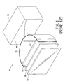
- FIG. 1 is an exploded view of a conventional vertical backlight module
- FIG. 2 is a cross-sectional view of a conventional vertical backlight module in use
- FIG. 3 is a perspective view of a light guiding plate structure according to one embodiment of the invention.
- FIG. 4 is an exploded view of a vertical backlight module in which a light guiding plate structure according to one embodiment of the invention is mounted;
- FIG. 5 is a perspective view of a vertical backlight module according to one embodiment of the invention.
- FIG. 6 is a cross-sectional view of a vertical backlight module in use according to one embodiment of the invention.
- FIG. 7 is an enlarged view of part A of FIG. 6 ;
- FIG. 8 is a perspective view of a light guiding plate according to another embodiment of the invention.
- the invention provides. a light guiding plate 1 that is flat and made of transparent material. At a bottom of the light guiding plate 1 is formed a flat light incidence surface 2 . At a top of the light guiding plate 1 is formed a light emergence surface 3 with a concave portion 30 .
- the concave portion 30 consists of segments with various curvatures being smoothly connected to one another.
- the light guiding plate 1 is mounted inside a vertical backlight module 4 .
- the vertical backlight module 4 includes a base 40 , a reflector 41 , an illumination element 42 , a diffusion plate 43 , and a liquid crystal module 44 .
- the base 40 is a rectangular solid and has a curved inner surface 45 to attach to the reflector 41 .
- the illumination element 42 is mounted approximately in a central location of the base 40 and above the reflector 41 . Then, the light guiding plate 1 , the diffusion plate 43 and the liquid crystal module 44 are sequentially mounted in the base 40 .
- the method used to assemble the module 4 and the components of the module 4 are well known in the art and thus their detailed description is omitted herein.
- the light guiding plate 1 is mounted between the illumination element 42 and the diffusion plate 43 , the light incidence surface 2 facing the illumination element 42 and the light emergence surface 3 being adjacent to the diffusion plate 43 .
- the concave portion 30 has a length not less than the illumination element 42 and located right above a top of the illumination element 42 .
- FIG. 6 and FIG. 7 are cross-sectional views showing the illumination of the illumination element 42 .
- Light irradiated from the illumination element 42 travels respectively through the light incidence surface 2 , the main portion of the light guiding plate 1 and the light emergence surface 3 .
- the light transmitted through the light guiding plate 1 right above the illumination element 42 is outwardly diffused by the concave surface 30 before being transmitted through the light emergence. surface 3 .
- the intensity of the light transmitted through the portion of the light guiding plate 1 right above the illumination element 42 is as uniform as through the remaining portions of the light guiding plate 1 .
- the light guiding plate 1 has a uniform light emergence in each portion without any intensively bright area as encountered in the prior art (as shown in FIG. 2 ).
- the light incidence surface 2 can optionally be provided with a plurality of strip-shaped patterns (not shown) to further diffuse the light and provide the display of the backlight module with a higher glow and homogeneity.
- FIG. 8 is a perspective view of a light guiding plate according to another embodiment of the invention.
- a light incidence surface 2 ′ of a light guiding plate 1 ′ complies with the profile of a light emergence surface 3 ′ so that the light guiding plate 1 ′ has an even thickness.
- the light guiding plate of the invention has the following advantages.
- the light transmitted through the light guiding plate right above the illumination element of the backlight module is evenly diffused by the concave portion. Therefore, the backlight module exhibits a higher glow and homogeneity. Furthermore, the total thickness of the vertical backlight module is reduced, which allows a minimization of the volume of the backlight module.
Landscapes
- Engineering & Computer Science (AREA)
- Multimedia (AREA)
- Signal Processing (AREA)
- Physics & Mathematics (AREA)
- Nonlinear Science (AREA)
- General Physics & Mathematics (AREA)
- Theoretical Computer Science (AREA)
- Chemical & Material Sciences (AREA)
- Crystallography & Structural Chemistry (AREA)
- Mathematical Physics (AREA)
- Optics & Photonics (AREA)
- General Engineering & Computer Science (AREA)
- Planar Illumination Modules (AREA)
- Liquid Crystal (AREA)
Abstract
A light guiding plate according to the invention is mounted in a vertical backlight module between an illumination element and a diffusion plate. The light guiding plate has a flat light incidence surface at a bottom of the light guiding plate and a light emergence surface at a top of the light guiding plate. The light incidence surface faces the illumination element. The light emergence surface is adjacent to the diffusion plate and has a concave portion right above the illumination element. The concave portion of the light guiding plate further diffuses the light transmitted right above the illumination element to homogenize the light emergence and increase the glow for display of the backlight module. The total thickness of the vertical backlight module thereby is reduced to minimize the volume of the backlight module.
Description
1. Field of the Invention
The invention relates to a light guiding plate. More particularly, the invention provides a light guiding plate used in a vertical backlight module of a liquid crystal display, a scanner or an advertisement panel.
2. Description of the Related Art
Display devices play an important role in communicating information through images. A CRT-type display device uses an electron beam to display images on a curved or flat panel. A picture tube of the CRT-type display device occupies a substantially large space to provide the necessary electron beam. A principal disadvantage of the CRT display therefore is the space occupied thereby.
Recently, a compact display device such as a liquid crystal flat display has been developed and put into production. It has become popular due to its low weight and space saving advantages. Laptop computers are consequently made increasingly thinner and more compact by employment of liquid crystal displays, to facilitate transportation thereof. Increasingly, desktop computers are also equipped with liquid crystal display devices since the price of the liquid crystal display devices has dropped. Space reduction of the display device brings the user a comfort of use and allows him/her to fully utilize the working space.
The optical module assembled with a light guiding plate realizes the flattening of the display device. Referring to FIG. 1 , a conventional vertical backlight module 9 includes a base 90, a reflector 91, an illumination element 92, a light guiding plate 93, a diffusion plate 94 and a liquid crystal module 95. The base 90 is a rectangular solid and has a curved inner surface 96 to attach to the arc-like reflector 91. The illumination element 92 is mounted in an approximately central location of the base 90 and above the reflector 91. Opposite sides of the rectangular light guiding plate 93 are respectively fastened to a surface 96 of the base 90. The rectangular diffusion plate 94 is also fastened to the surface 96 and attached on the light guiding plate 93. Then, the liquid crystal module 95 is attached on the diffusion plate 94. Thereby, a conventional vertical backlight module 9 is accomplished.
In the above structure of the conventional backlight module 9 (as shown in FIG. 2), light irradiated from a lower part of the illumination element 92 and reflected by the reflector 91 is transmitted to the light guiding plate 93. Light irradiated from an upper part of the illumination element 92 is guided directly to the light guiding plate 93 without reflection. In particular, the light irradiated right from the top of the illumination element 92 is transmitted directly to the light guiding plate with the shortest transmission distance. Since the light guiding plate 93 is flat, all the incident light is guided to the diffusion plate 94 at a constant angle. The distribution of the incident light in the diffusion plate 94 is the same as that of emergent light from the light guiding plate 93. Therefore, the light intensity at the area right above the illumination element 92 of the backlight module 9 is substantially higher than that at other areas. This causes an uneven light emergence on the whole display of the backlight module 9. As a result, the glow of the vertical backlight module 9 is adversely affected.
It is therefore a principal object of the invention to provide a light guiding plate by which the light emergence is homogenized for display of the backlight module.
It is another object of the invention to provide a light guiding plate by which the total thickness of the vertical backlight module is reduced to minimize the volume of the backlight module.
To accomplish the above and other objectives, the invention provides a light guiding plate that is mounted in a vertical backlight module between an illumination element and a diffusion plate. The light guiding plate has a flat light incidence surface at a bottom of the light guiding plate and a light emergence surface at a top of the light guiding plate. The light incidence surface faces the illumination element. The light emergence surface is adjacent to the diffusion plate and has a concave portion right above the illumination element. The concave portion of the light guiding plate further diffuses the light transmitted right above the illumination element to homogenize the light emergence and increase the glow for display of the backlight module. The total thickness of the vertical backlight module can be thus reduced to minimize the volume of the backlight module.
To provide a further understanding of the invention, the following detailed description illustrates embodiments and examples of the invention, this detailed description being provided only for illustration of the invention.
The drawings included herein provide a further understanding of the invention. A brief introduction of the drawings is as follows:
Wherever possible in the following description, like reference numerals will refer to like elements and parts unless otherwise. illustrated.
Referring to FIG. 3 , the invention provides. a light guiding plate 1 that is flat and made of transparent material. At a bottom of the light guiding plate 1 is formed a flat light incidence surface 2. At a top of the light guiding plate 1 is formed a light emergence surface 3 with a concave portion 30. The concave portion 30 consists of segments with various curvatures being smoothly connected to one another.
Referring to FIG. 3 through FIG. 6 , the light guiding plate 1 is mounted inside a vertical backlight module 4. The vertical backlight module 4 includes a base 40, a reflector 41, an illumination element 42, a diffusion plate 43, and a liquid crystal module 44. The base 40 is a rectangular solid and has a curved inner surface 45 to attach to the reflector 41. The illumination element 42 is mounted approximately in a central location of the base 40 and above the reflector 41. Then, the light guiding plate 1, the diffusion plate 43 and the liquid crystal module 44 are sequentially mounted in the base 40. The method used to assemble the module 4 and the components of the module 4 are well known in the art and thus their detailed description is omitted herein.
The light guiding plate 1 is mounted between the illumination element 42 and the diffusion plate 43, the light incidence surface 2 facing the illumination element 42 and the light emergence surface 3 being adjacent to the diffusion plate 43. The concave portion 30 has a length not less than the illumination element 42 and located right above a top of the illumination element 42.
FIG. 6 and FIG. 7 are cross-sectional views showing the illumination of the illumination element 42. Light irradiated from the illumination element 42 travels respectively through the light incidence surface 2, the main portion of the light guiding plate 1 and the light emergence surface 3. The light transmitted through the light guiding plate 1 right above the illumination element 42 is outwardly diffused by the concave surface 30 before being transmitted through the light emergence. surface 3. Thereby, the intensity of the light transmitted through the portion of the light guiding plate 1 right above the illumination element 42 is as uniform as through the remaining portions of the light guiding plate 1. The light guiding plate 1 has a uniform light emergence in each portion without any intensively bright area as encountered in the prior art (as shown in FIG. 2). The undesired presence of an intensively bright area right above the illumination element 92 which causes uneven glow and homogeneity at the display panel thereby is prevented. Furthermore, the light incidence surface 2 can optionally be provided with a plurality of strip-shaped patterns (not shown) to further diffuse the light and provide the display of the backlight module with a higher glow and homogeneity.
As described above, the light guiding plate of the invention has the following advantages. The light transmitted through the light guiding plate right above the illumination element of the backlight module is evenly diffused by the concave portion. Therefore, the backlight module exhibits a higher glow and homogeneity. Furthermore, the total thickness of the vertical backlight module is reduced, which allows a minimization of the volume of the backlight module.
Those skilled in the art will readily appreciate that the above description is only illustrative of specific embodiments and examples of the invention. The invention should therefore cover various modifications and variations made to the herein-described structure and operations of the invention, provided they fall within the scope of the invention as defined in the following appended claims.
Claims (8)
1. A light guiding plate, mounted in a vertical backlight module and between an illumination element and a diffusion plate arranged on the vertical backlight module, the light guiding plate comprising a flat light incidence surface at a bottom thereof and a light emergence surface at a top thereof, wherein the light incidence surface faces the illumination element, wherein the light emergence surface has a flat portion for abutting the diffusion plate and a concave portion positioned on a middle of the flat portion for aligning the illumination element, and the concave portion having a curved surface to diffuse light transmitted right above the illumination element, homogenize the light emergence and increase a glow for display of the backlight module.
2. The light guiding plate of claim 1 , wherein the light guiding plate is made of a transparent material.
3. The light guiding plate of claim 1 , wherein the light incidence surface is a flat surface.
4. The light guiding plate of claim 1 , wherein the light incidence surface is further provided with a plurality of strip-shaped patterns.
5. The light guiding plate of claim 1 , wherein the concave portion of the light emergence surface consists of segments with various curvatures being smoothly connected to one another.
6. The light guiding plate of claim 1 , wherein the concave portion of the light emergence surface is as large as the illumination element.
7. The light guiding plate of claim 1 , wherein the concave portion of the light emergence surface is larger than the illumination element.
8. The light guiding plate of claim 1 , wherein the light incidence surface complies with a profile of the light emergence surface.
Priority Applications (1)
| Application Number | Priority Date | Filing Date | Title |
|---|---|---|---|
| US10/377,420 US6840656B2 (en) | 2003-02-27 | 2003-02-27 | Light guiding plate for backlight module |
Applications Claiming Priority (1)
| Application Number | Priority Date | Filing Date | Title |
|---|---|---|---|
| US10/377,420 US6840656B2 (en) | 2003-02-27 | 2003-02-27 | Light guiding plate for backlight module |
Publications (2)
| Publication Number | Publication Date |
|---|---|
| US20040170021A1 US20040170021A1 (en) | 2004-09-02 |
| US6840656B2 true US6840656B2 (en) | 2005-01-11 |
Family
ID=32908137
Family Applications (1)
| Application Number | Title | Priority Date | Filing Date |
|---|---|---|---|
| US10/377,420 Expired - Fee Related US6840656B2 (en) | 2003-02-27 | 2003-02-27 | Light guiding plate for backlight module |
Country Status (1)
| Country | Link |
|---|---|
| US (1) | US6840656B2 (en) |
Cited By (23)
| Publication number | Priority date | Publication date | Assignee | Title |
|---|---|---|---|---|
| US20050018414A1 (en) * | 2003-07-25 | 2005-01-27 | Ming-Chiang Tsai | Illuminated logo unit with reflective device |
| US20070091584A1 (en) * | 2005-10-21 | 2007-04-26 | Hon Hai Precision Industry Co., Ltd. | Spacer and backlight module using the same |
| US20070196762A1 (en) * | 2006-02-20 | 2007-08-23 | Toyoda Gosei Co., Ltd. | Scuff plate |
| US20090059563A1 (en) * | 2005-06-28 | 2009-03-05 | Sharp Kabushiki Kaisha | Illumination device for display device, display device, and television receiver |
| US20110210579A1 (en) * | 2010-03-01 | 2011-09-01 | Sabic Innovative Plastics Ip B.V. | Energy absorber elements and vehicle systems |
| US20140355302A1 (en) * | 2013-03-15 | 2014-12-04 | Cree, Inc. | Outdoor and/or Enclosed Structure LED Luminaire for General Illumination Applications, Such as Parking Lots and Structures |
| US9291320B2 (en) | 2013-01-30 | 2016-03-22 | Cree, Inc. | Consolidated troffer |
| US9366799B2 (en) | 2013-03-15 | 2016-06-14 | Cree, Inc. | Optical waveguide bodies and luminaires utilizing same |
| US9366396B2 (en) | 2013-01-30 | 2016-06-14 | Cree, Inc. | Optical waveguide and lamp including same |
| US9389367B2 (en) | 2013-01-30 | 2016-07-12 | Cree, Inc. | Optical waveguide and luminaire incorporating same |
| US9442243B2 (en) | 2013-01-30 | 2016-09-13 | Cree, Inc. | Waveguide bodies including redirection features and methods of producing same |
| US9625638B2 (en) | 2013-03-15 | 2017-04-18 | Cree, Inc. | Optical waveguide body |
| US9645303B2 (en) | 2013-03-15 | 2017-05-09 | Cree, Inc. | Luminaires utilizing edge coupling |
| US9690029B2 (en) | 2013-01-30 | 2017-06-27 | Cree, Inc. | Optical waveguides and luminaires incorporating same |
| US9798072B2 (en) | 2013-03-15 | 2017-10-24 | Cree, Inc. | Optical element and method of forming an optical element |
| US9869432B2 (en) | 2013-01-30 | 2018-01-16 | Cree, Inc. | Luminaires using waveguide bodies and optical elements |
| US9920901B2 (en) | 2013-03-15 | 2018-03-20 | Cree, Inc. | LED lensing arrangement |
| US10209429B2 (en) | 2013-03-15 | 2019-02-19 | Cree, Inc. | Luminaire with selectable luminous intensity pattern |
| US10416377B2 (en) | 2016-05-06 | 2019-09-17 | Cree, Inc. | Luminaire with controllable light emission |
| US10436970B2 (en) | 2013-03-15 | 2019-10-08 | Ideal Industries Lighting Llc | Shaped optical waveguide bodies |
| US10502899B2 (en) * | 2013-03-15 | 2019-12-10 | Ideal Industries Lighting Llc | Outdoor and/or enclosed structure LED luminaire |
| US11112083B2 (en) | 2013-03-15 | 2021-09-07 | Ideal Industries Lighting Llc | Optic member for an LED light fixture |
| US11719882B2 (en) | 2016-05-06 | 2023-08-08 | Ideal Industries Lighting Llc | Waveguide-based light sources with dynamic beam shaping |
Citations (6)
| Publication number | Priority date | Publication date | Assignee | Title |
|---|---|---|---|---|
| US4660936A (en) * | 1986-01-02 | 1987-04-28 | Rca Corporation | Arrangement to minimize reflected ambient light in a display |
| US5143433A (en) * | 1991-11-01 | 1992-09-01 | Litton Systems Canada Limited | Night vision backlighting system for liquid crystal displays |
| US5357405A (en) * | 1992-11-13 | 1994-10-18 | Samsung Display Devices Co., Ltd. | Backlighting device for liquid crystal devices |
| US5479275A (en) * | 1993-12-03 | 1995-12-26 | Ois Optical Imaging Systems, Inc. | Backlit liquid crystal display with integral collimating, refracting, and reflecting means which refracts and collimates light from a first light source and reflects light from a second light source |
| US5479328A (en) * | 1994-01-05 | 1995-12-26 | Interstate Electronics Corporation | High-brightness, high-efficacy backlight |
| US5986728A (en) * | 1997-07-23 | 1999-11-16 | Litton Systems, Inc. | Optically enhance day/night liquid crystal display backlight with TIR lens and both light sources on same side of waveguide |
-
2003
- 2003-02-27 US US10/377,420 patent/US6840656B2/en not_active Expired - Fee Related
Patent Citations (7)
| Publication number | Priority date | Publication date | Assignee | Title |
|---|---|---|---|---|
| US4660936A (en) * | 1986-01-02 | 1987-04-28 | Rca Corporation | Arrangement to minimize reflected ambient light in a display |
| US4660936B1 (en) * | 1986-01-02 | 1990-01-23 | Rca Corp | |
| US5143433A (en) * | 1991-11-01 | 1992-09-01 | Litton Systems Canada Limited | Night vision backlighting system for liquid crystal displays |
| US5357405A (en) * | 1992-11-13 | 1994-10-18 | Samsung Display Devices Co., Ltd. | Backlighting device for liquid crystal devices |
| US5479275A (en) * | 1993-12-03 | 1995-12-26 | Ois Optical Imaging Systems, Inc. | Backlit liquid crystal display with integral collimating, refracting, and reflecting means which refracts and collimates light from a first light source and reflects light from a second light source |
| US5479328A (en) * | 1994-01-05 | 1995-12-26 | Interstate Electronics Corporation | High-brightness, high-efficacy backlight |
| US5986728A (en) * | 1997-07-23 | 1999-11-16 | Litton Systems, Inc. | Optically enhance day/night liquid crystal display backlight with TIR lens and both light sources on same side of waveguide |
Cited By (35)
| Publication number | Priority date | Publication date | Assignee | Title |
|---|---|---|---|---|
| US20050018414A1 (en) * | 2003-07-25 | 2005-01-27 | Ming-Chiang Tsai | Illuminated logo unit with reflective device |
| US7192148B2 (en) * | 2003-07-25 | 2007-03-20 | Hon Hai Precision Ind. Co., Ltd. | Illuminated logo unit with reflective device |
| US20090059563A1 (en) * | 2005-06-28 | 2009-03-05 | Sharp Kabushiki Kaisha | Illumination device for display device, display device, and television receiver |
| US20070091584A1 (en) * | 2005-10-21 | 2007-04-26 | Hon Hai Precision Industry Co., Ltd. | Spacer and backlight module using the same |
| US7407318B2 (en) * | 2005-10-21 | 2008-08-05 | Hon Hai Precision Industry Co., Ltd. | Spacer and backlight module using the same |
| US20070196762A1 (en) * | 2006-02-20 | 2007-08-23 | Toyoda Gosei Co., Ltd. | Scuff plate |
| US20110210579A1 (en) * | 2010-03-01 | 2011-09-01 | Sabic Innovative Plastics Ip B.V. | Energy absorber elements and vehicle systems |
| US9291320B2 (en) | 2013-01-30 | 2016-03-22 | Cree, Inc. | Consolidated troffer |
| US9823408B2 (en) | 2013-01-30 | 2017-11-21 | Cree, Inc. | Optical waveguide and luminaire incorporating same |
| US10436969B2 (en) | 2013-01-30 | 2019-10-08 | Ideal Industries Lighting Llc | Optical waveguide and luminaire incorporating same |
| US9366396B2 (en) | 2013-01-30 | 2016-06-14 | Cree, Inc. | Optical waveguide and lamp including same |
| US9389367B2 (en) | 2013-01-30 | 2016-07-12 | Cree, Inc. | Optical waveguide and luminaire incorporating same |
| US9442243B2 (en) | 2013-01-30 | 2016-09-13 | Cree, Inc. | Waveguide bodies including redirection features and methods of producing same |
| US9519095B2 (en) | 2013-01-30 | 2016-12-13 | Cree, Inc. | Optical waveguides |
| US9581751B2 (en) | 2013-01-30 | 2017-02-28 | Cree, Inc. | Optical waveguide and lamp including same |
| US9869432B2 (en) | 2013-01-30 | 2018-01-16 | Cree, Inc. | Luminaires using waveguide bodies and optical elements |
| US11644157B2 (en) | 2013-01-30 | 2023-05-09 | Ideal Industries Lighting Llc | Luminaires using waveguide bodies and optical elements |
| US9690029B2 (en) | 2013-01-30 | 2017-06-27 | Cree, Inc. | Optical waveguides and luminaires incorporating same |
| US9645303B2 (en) | 2013-03-15 | 2017-05-09 | Cree, Inc. | Luminaires utilizing edge coupling |
| US9366799B2 (en) | 2013-03-15 | 2016-06-14 | Cree, Inc. | Optical waveguide bodies and luminaires utilizing same |
| US9625638B2 (en) | 2013-03-15 | 2017-04-18 | Cree, Inc. | Optical waveguide body |
| US9920901B2 (en) | 2013-03-15 | 2018-03-20 | Cree, Inc. | LED lensing arrangement |
| US10168467B2 (en) | 2013-03-15 | 2019-01-01 | Cree, Inc. | Luminaires utilizing edge coupling |
| US10209429B2 (en) | 2013-03-15 | 2019-02-19 | Cree, Inc. | Luminaire with selectable luminous intensity pattern |
| US10379278B2 (en) * | 2013-03-15 | 2019-08-13 | Ideal Industries Lighting Llc | Outdoor and/or enclosed structure LED luminaire outdoor and/or enclosed structure LED luminaire having outward illumination |
| US20140355302A1 (en) * | 2013-03-15 | 2014-12-04 | Cree, Inc. | Outdoor and/or Enclosed Structure LED Luminaire for General Illumination Applications, Such as Parking Lots and Structures |
| US10436970B2 (en) | 2013-03-15 | 2019-10-08 | Ideal Industries Lighting Llc | Shaped optical waveguide bodies |
| US9798072B2 (en) | 2013-03-15 | 2017-10-24 | Cree, Inc. | Optical element and method of forming an optical element |
| US10502899B2 (en) * | 2013-03-15 | 2019-12-10 | Ideal Industries Lighting Llc | Outdoor and/or enclosed structure LED luminaire |
| US11112083B2 (en) | 2013-03-15 | 2021-09-07 | Ideal Industries Lighting Llc | Optic member for an LED light fixture |
| US10890714B2 (en) | 2016-05-06 | 2021-01-12 | Ideal Industries Lighting Llc | Waveguide-based light sources with dynamic beam shaping |
| US10527785B2 (en) | 2016-05-06 | 2020-01-07 | Ideal Industries Lighting Llc | Waveguide-based light sources with dynamic beam shaping |
| US11372156B2 (en) | 2016-05-06 | 2022-06-28 | Ideal Industries Lighting Llc | Waveguide-based light sources with dynamic beam shaping |
| US10416377B2 (en) | 2016-05-06 | 2019-09-17 | Cree, Inc. | Luminaire with controllable light emission |
| US11719882B2 (en) | 2016-05-06 | 2023-08-08 | Ideal Industries Lighting Llc | Waveguide-based light sources with dynamic beam shaping |
Also Published As
| Publication number | Publication date |
|---|---|
| US20040170021A1 (en) | 2004-09-02 |
Similar Documents
| Publication | Publication Date | Title |
|---|---|---|
| US6840656B2 (en) | Light guiding plate for backlight module | |
| EP1876388B1 (en) | Light guide member and backlight unit including light guide member | |
| US7470046B2 (en) | Backlight module and illumination device thereof | |
| TWI299422B (en) | ||
| US20070147089A1 (en) | Backlight module and lcd having same | |
| JP2004199967A (en) | Planar light source device, liquid crystal display device, and display device | |
| JP4607225B2 (en) | Light source module, liquid crystal display device and lighting device | |
| CN103765619B (en) | Light-emitting device and display device | |
| US6913378B2 (en) | Direct-lighting type back light unit | |
| KR20170035500A (en) | Backlight unit and display appratus having the same | |
| US7463315B2 (en) | Light coupling structure on light guide plate in a backlight module | |
| US20080112188A1 (en) | Diffusion plate of backlight structure and display device using the same | |
| JP4256540B2 (en) | Surface light source device | |
| KR100790497B1 (en) | Direct type backlight unit | |
| US20030107892A1 (en) | Lamp reflecting apparatus used in direct under type backlight module | |
| TWI405008B (en) | Backlight module and display device having the same | |
| US20050088838A1 (en) | Light guiding device with two opposite light emitting surfaces and backlight module using the same | |
| US8520166B2 (en) | Backlight unit and liquid crystal display device having the same | |
| US6755548B2 (en) | Backlight module | |
| KR101832483B1 (en) | Backlight unit and liquid crystal display device and method having the same | |
| KR20020057755A (en) | Liquid Crystal Display Device having a novel Direct Back-lighting Assembly | |
| CN100426081C (en) | Lighting apparatus having a uniform luminance profile | |
| KR19980065999U (en) | Backlight Structure of LCD | |
| KR100500638B1 (en) | Backlight device of LCD module | |
| US7832915B2 (en) | Surface light source device and image display unit |
Legal Events
| Date | Code | Title | Description |
|---|---|---|---|
| FEPP | Fee payment procedure |
Free format text: PAYOR NUMBER ASSIGNED (ORIGINAL EVENT CODE: ASPN); ENTITY STATUS OF PATENT OWNER: SMALL ENTITY |
|
| REMI | Maintenance fee reminder mailed | ||
| LAPS | Lapse for failure to pay maintenance fees | ||
| STCH | Information on status: patent discontinuation |
Free format text: PATENT EXPIRED DUE TO NONPAYMENT OF MAINTENANCE FEES UNDER 37 CFR 1.362 |
|
| FP | Lapsed due to failure to pay maintenance fee |
Effective date: 20090111 |