US6792486B1 - System and method for managing information storage among plural disk drives - Google Patents
System and method for managing information storage among plural disk drives Download PDFInfo
- Publication number
- US6792486B1 US6792486B1 US10/137,237 US13723702A US6792486B1 US 6792486 B1 US6792486 B1 US 6792486B1 US 13723702 A US13723702 A US 13723702A US 6792486 B1 US6792486 B1 US 6792486B1
- Authority
- US
- United States
- Prior art keywords
- frame
- controller
- plural
- disk drives
- disk drive
- Prior art date
- Legal status (The legal status is an assumption and is not a legal conclusion. Google has not performed a legal analysis and makes no representation as to the accuracy of the status listed.)
- Expired - Lifetime, expires
Links
Images


Classifications
-
- G—PHYSICS
- G06—COMPUTING OR CALCULATING; COUNTING
- G06F—ELECTRIC DIGITAL DATA PROCESSING
- G06F3/00—Input arrangements for transferring data to be processed into a form capable of being handled by the computer; Output arrangements for transferring data from processing unit to output unit, e.g. interface arrangements
- G06F3/06—Digital input from, or digital output to, record carriers, e.g. RAID, emulated record carriers or networked record carriers
- G06F3/0601—Interfaces specially adapted for storage systems
- G06F3/0628—Interfaces specially adapted for storage systems making use of a particular technique
- G06F3/0629—Configuration or reconfiguration of storage systems
- G06F3/0635—Configuration or reconfiguration of storage systems by changing the path, e.g. traffic rerouting, path reconfiguration
-
- G—PHYSICS
- G06—COMPUTING OR CALCULATING; COUNTING
- G06F—ELECTRIC DIGITAL DATA PROCESSING
- G06F11/00—Error detection; Error correction; Monitoring
- G06F11/07—Responding to the occurrence of a fault, e.g. fault tolerance
- G06F11/16—Error detection or correction of the data by redundancy in hardware
- G06F11/20—Error detection or correction of the data by redundancy in hardware using active fault-masking, e.g. by switching out faulty elements or by switching in spare elements
- G06F11/2053—Error detection or correction of the data by redundancy in hardware using active fault-masking, e.g. by switching out faulty elements or by switching in spare elements where persistent mass storage functionality or persistent mass storage control functionality is redundant
- G06F11/2089—Redundant storage control functionality
-
- G—PHYSICS
- G06—COMPUTING OR CALCULATING; COUNTING
- G06F—ELECTRIC DIGITAL DATA PROCESSING
- G06F11/00—Error detection; Error correction; Monitoring
- G06F11/07—Responding to the occurrence of a fault, e.g. fault tolerance
- G06F11/16—Error detection or correction of the data by redundancy in hardware
- G06F11/20—Error detection or correction of the data by redundancy in hardware using active fault-masking, e.g. by switching out faulty elements or by switching in spare elements
- G06F11/2053—Error detection or correction of the data by redundancy in hardware using active fault-masking, e.g. by switching out faulty elements or by switching in spare elements where persistent mass storage functionality or persistent mass storage control functionality is redundant
- G06F11/2094—Redundant storage or storage space
-
- G—PHYSICS
- G06—COMPUTING OR CALCULATING; COUNTING
- G06F—ELECTRIC DIGITAL DATA PROCESSING
- G06F11/00—Error detection; Error correction; Monitoring
- G06F11/07—Responding to the occurrence of a fault, e.g. fault tolerance
- G06F11/16—Error detection or correction of the data by redundancy in hardware
- G06F11/20—Error detection or correction of the data by redundancy in hardware using active fault-masking, e.g. by switching out faulty elements or by switching in spare elements
- G06F11/2097—Error detection or correction of the data by redundancy in hardware using active fault-masking, e.g. by switching out faulty elements or by switching in spare elements maintaining the standby controller/processing unit updated
-
- G—PHYSICS
- G06—COMPUTING OR CALCULATING; COUNTING
- G06F—ELECTRIC DIGITAL DATA PROCESSING
- G06F3/00—Input arrangements for transferring data to be processed into a form capable of being handled by the computer; Output arrangements for transferring data from processing unit to output unit, e.g. interface arrangements
- G06F3/06—Digital input from, or digital output to, record carriers, e.g. RAID, emulated record carriers or networked record carriers
- G06F3/0601—Interfaces specially adapted for storage systems
- G06F3/0602—Interfaces specially adapted for storage systems specifically adapted to achieve a particular effect
- G06F3/0626—Reducing size or complexity of storage systems
-
- G—PHYSICS
- G06—COMPUTING OR CALCULATING; COUNTING
- G06F—ELECTRIC DIGITAL DATA PROCESSING
- G06F3/00—Input arrangements for transferring data to be processed into a form capable of being handled by the computer; Output arrangements for transferring data from processing unit to output unit, e.g. interface arrangements
- G06F3/06—Digital input from, or digital output to, record carriers, e.g. RAID, emulated record carriers or networked record carriers
- G06F3/0601—Interfaces specially adapted for storage systems
- G06F3/0668—Interfaces specially adapted for storage systems adopting a particular infrastructure
- G06F3/0671—In-line storage system
- G06F3/0683—Plurality of storage devices
- G06F3/0689—Disk arrays, e.g. RAID, JBOD
-
- G—PHYSICS
- G06—COMPUTING OR CALCULATING; COUNTING
- G06F—ELECTRIC DIGITAL DATA PROCESSING
- G06F11/00—Error detection; Error correction; Monitoring
- G06F11/07—Responding to the occurrence of a fault, e.g. fault tolerance
- G06F11/16—Error detection or correction of the data by redundancy in hardware
- G06F11/1658—Data re-synchronization of a redundant component, or initial sync of replacement, additional or spare unit
- G06F11/1662—Data re-synchronization of a redundant component, or initial sync of replacement, additional or spare unit the resynchronized component or unit being a persistent storage device
-
- G—PHYSICS
- G06—COMPUTING OR CALCULATING; COUNTING
- G06F—ELECTRIC DIGITAL DATA PROCESSING
- G06F11/00—Error detection; Error correction; Monitoring
- G06F11/07—Responding to the occurrence of a fault, e.g. fault tolerance
- G06F11/16—Error detection or correction of the data by redundancy in hardware
- G06F11/20—Error detection or correction of the data by redundancy in hardware using active fault-masking, e.g. by switching out faulty elements or by switching in spare elements
- G06F11/2053—Error detection or correction of the data by redundancy in hardware using active fault-masking, e.g. by switching out faulty elements or by switching in spare elements where persistent mass storage functionality or persistent mass storage control functionality is redundant
- G06F11/2056—Error detection or correction of the data by redundancy in hardware using active fault-masking, e.g. by switching out faulty elements or by switching in spare elements where persistent mass storage functionality or persistent mass storage control functionality is redundant by mirroring
- G06F11/2087—Error detection or correction of the data by redundancy in hardware using active fault-masking, e.g. by switching out faulty elements or by switching in spare elements where persistent mass storage functionality or persistent mass storage control functionality is redundant by mirroring with a common controller
Definitions
- the present invention relates generally to information storage systems. More particularly, the present invention relates to a system and method for managing information storage among plural disk drives.
- Computing systems store data within electronic storage devices such as hard disk drives.
- the storage capacity of these storage devices has rapidly increased as the demands for storage made by modem computing systems have increased.
- With the increase in capacity there has been a concurrent increase in the performance of these storage devices as the processing speed and power of modem computing systems have improved.
- Many users, such as the high-end enterprise market have become highly dependent on these high performance, high capacity storage devices.
- a need for increased reliability of such storage subsystems has also developed.
- Disk array storage systems provide both improved capacity and performance, as compared to single disk devices.
- multiple disk drives are used in a cooperative manner to perform, in parallel, the tasks normally performed by a single disk drive.
- data is stored in a distributed manner throughout the disk drives for parallel, high-speed access.
- striping techniques are often used to spread large amounts of information over the multiple disk drives in the disk array storage system.
- adding multiple disk drives to a storage system reduces the reliability of the overall storage system.
- spreading data over multiple disk drives in a disk array increases the potential for system failure. Failure of any of the multiple disk drives translates to failure of the storage system, because the data stored on the disk drives cannot be correctly retrieved.
- RAID Redundant Array of Inexpensive Disks, also known as Redundant Array of Independent Disks
- RAID level 0 provides disk-striping capabilities for improved performance, but without an accompanying increase in reliability.
- RAID levels 1 - 6 RAID levels 1 - 6 that configure multiple disk drives in the disk array in geometries that permit redundancy of stored data to assure data integrity in case of various failures.
- the fundamental concepts of RAID technology are discussed in, for example, U.S. Pat. No. 5,950,230, the disclosure of which is hereby incorporated by reference in its entirety.
- the multiple disk drives are organized into disk arrays that are managed by an array controller.
- the array controller presents the disk array to the user as one or more disk drives and shields the user or host system from the details of managing the redundant array.
- the cost and complexity of the array controller increases with the increased reliability offered by the higher RAID levels.
- RAID level 6 provides for recovery from a two-drive failure, but at a penalty in cost and complexity of the array controller, because the Reed-Solomon codes used in RAID level 6 are complex and can require significant computational resources.
- the system includes plural host interfaces and first and second elements.
- the first and second elements each comprise a set of disk drives for storing information.
- Each of the first and second elements is associated with an element frame.
- Each disk drive included in the first element is connected to a different one of the plural host interfaces during the element frame of the first element.
- the system includes a switch controller, configurable by at least one of the plural host interfaces, for selecting among the first and second elements, and for directing information from a first one of the plural host interfaces to a selected disk drive within the first element.
- the system also includes a frame controller for controlling a duration of each element frame.
- the present invention may also be regarded as a method for managing information storage among plural disk drives.
- a switch controller selects among first and second elements.
- the first and second elements each comprise a set of disk drives for storing information.
- Each of the first and second elements is associated with an element frame.
- Each disk drive included in the first element is connected to a different one of plural host interfaces during the element frame of the first element.
- the switch controller is configurable by at least one of the plural host interfaces.
- the switch controller directs information from a first one of the plural host interfaces to a selected disk drive within the first element.
- a frame controller controls a duration of each element frame.
- FIG. 1 is a block diagram of a system for managing information storage among plural disk drives in accordance with an exemplary embodiment of the present invention.
- FIG. 2 is a block diagram illustrating a relationship of element frames to elements in accordance with an exemplary embodiment of the present invention.
- FIG. 3 is a block diagram illustrating a relationship between element frames and elements in accordance with an exemplary embodiment of the present invention.
- FIG. 4 illustrates an exemplary tag for communicating information in accordance with an exemplary embodiment of the present invention.
- FIGS. 5A and 5B are flowcharts illustrating steps for managing information storage among plural disk drives in accordance with an exemplary embodiment of the present invention.
- FIG. 6 is a flowchart illustrating steps for processing a broadcast frame by a switch controller in accordance with an exemplary embodiment of the present invention.
- FIG. 7 is a flowchart illustrating steps for controlling frame sequence and frame skipping by a switch controller in accordance with an exemplary embodiment of the present invention.
- FIG. 8 is a flowchart illustrating steps for controlling frame duration and frame termination by a frame controller in accordance with an exemplary embodiment of the present invention.
- FIG. 1 a block diagram of a system 100 for managing information storage among plural disk drives in accordance with an exemplary embodiment of the present invention.
- system 100 includes plural host interfaces 140 .
- Each of plural host interfaces 140 can be any disk drive host interface, such as, for example, a SATA (serial advanced technology attachment) interface, a SAS (serial attached small computer system interface (SCSI)) interface, a fibre channel interface, an Ethernet interface, an InfiniBandTM interface, or any other serial disk drive host interface that can be used for accessing disk drives.
- SATA serial advanced technology attachment
- SAS serial attached small computer system interface
- a fibre channel interface such as, for example, a SATA (serial advanced technology attachment) interface, a SAS (serial attached small computer system interface (SCSI)) interface, a fibre channel interface, an Ethernet interface, an InfiniBandTM interface, or any other serial disk drive host interface that can be used for accessing disk drives.
- SATA serial advanced technology attachment
- SAS serial attached small computer system interface
- system 100 includes first element 160 and second element 170 .
- First element 160 and second element 170 each comprise a set of disk drives for storing information.
- a “disk drive” can be any form of hard disk drive, such as a magnetic hard disk drive for storing computer data or any type of computer memory that can emulate a hard disk drive (e.g., a Random Access Memory (RAM) drive, which is a memory-resident program that uses part of a computer's RAM as if it were a hard disk drive).
- RAM Random Access Memory
- an “element” is a collection or set of disk drives that can be connected or otherwise allocated to the their respective host interfaces 140 .
- first element 160 includes disk drives 162 and 164
- second element 170 includes disk drives 172 and 174
- elements can include any number of disk drives.
- each disk drive contained in the first and second elements is a SATA disk drive or A SAS disk drive, although each disk drive can be any type of disk drive that is accessible via a serial interface and that is compliant with plural host interfaces 140 .
- System 100 includes plural switches 130 for connecting each disk drive to a different one of plural host interfaces 140 .
- each of the plural disk drives in system 100 has an associated switch 130 to connect each disk drive to its associated one of plural host interfaces 140 .
- Switch 130 can be any type of electronic or electro-optical switch capable of satisfying the requirements of each serial interface.
- the serial interfaces can have the same or different requirements.
- Each of the first element 160 and second element 170 is associated with an element frame, with each disk drive included in the first element being connected to a different one of the plural host interfaces 140 during the element frame of the first element.
- there can be a one-to-one ratio of disk drives in an element to host interfaces although any ratio of disk drives to host interfaces can be used.
- an “element frame” is a duration of time during which the disk drives in an element are allocated, enabled, connected or otherwise instantiated to their respective host interfaces for communication with their respective host interfaces.
- system 100 includes a switch controller 101 for selecting among first element 160 and second element 170 , although switch controller 101 can select among any number of elements.
- Switch controller 101 is configurable by at least one of plural host interfaces 140 .
- Switch controller 101 directs information from a first one of plural host interfaces 140 to a selected disk drive within first element 160 , although switch controller 101 can direct information from any of plural host interfaces 140 to any disk drive in any element of system 100 .
- switch controller 101 can include, for example, switch control processor 102 .
- Switch control processor 102 can be any type of processor, such as, for example, a microprocessor or firmware for processing commands and data from at least one of plural host interfaces 140 .
- Switch control processor 102 can also include any type of computer memory, such as, for example, random access memory (RAM), cache memory or any other computer memory located internally or externally to switch controller 101 , for receiving and storing information from at least one of plural host interfaces 140 .
- RAM random access memory
- each element frame is included in a master frame that contains multiple frame types.
- a “frame” is the time during which a particular function is performed in system 100 .
- an element frame is one type of frame.
- a “master frame” is a grouping of frames that are processed by system 100 in the sequence specified by the master frame.
- the master frame can include at least one of an element frame, a control frame, a broadcast frame, a poll frame, a copy frame, a mirror frame or any other type of frame that can be used or otherwise processed by system 100 to manage information storage.
- a master frame can include any combination of frames (including repetition of particular frames), of any type, in any number, and in any order or sequence. For purposes of illustration and not limitation, FIG.
- Master frame 200 includes six frames: control frame 205 , element frame 210 , element frame 215 , broadcast frame 220 , element frame 225 and copy frame 230 . Between each element frame is an inter-frame transition 235 , which is the time that system 100 takes to transition from one frame to another.
- element frames 210 , 215 and 225 can be different element frames or an element frame repeated one or more times within the master frame.
- control frame 205 connects at least one of plural host interfaces 140 to switch controller 101 to determine a status of, for example, switch controller 101 or any aspect of system 100 .
- Control frame 205 can identify at least one of a sequence and a maximum duration of each frame in the master frame (e.g., master frame 200 ), although control frame 205 can identify any durational measure of each frame (e.g., actual duration, minimum duration, average duration, etc.).
- a control frame can be enabled or otherwise instantiated at least on each pass of the master frame (e.g., as an individual frame in the master frame or inserted between frames during the inter-frame transition) for determining, for example, the status of switch controller 101 .
- a broadcast frame is a frame during which any type of host controller can communicate with all disk drives in system 100 using one or more of plural host interfaces 140 .
- a broadcast frame is a frame during which any one disk drive can communicate with any number of other disk drives in system 100 .
- each disk drive in system 100 can be connected to its respective host interface 140 through its respective switch 130 .
- all disk drives of all elements on the same host interface can receive information from a host controller during a broadcast frame.
- the host controller can communicate with any number of disk drives using any combination of plural host interfaces 140 .
- Switch controller 101 includes a means for recognizing the broadcast frame and for communicating broadcast information received from a host controller to the plural disk drives. According to exemplary embodiments, the host controller notifies switch controller 101 that a broadcast frame is to begin. For example, the host controller can issue any type of signal sequence, such as, for example, an interrupt, to switch control processor 101 at the start of a broadcast frame that indicates to switch control processor 101 that a broadcast frame is to begin. The signal sequence can indicate the host interfaces 140 over which the host controller is to communicate. Upon receipt and recognition of the signal sequence, switch control processor 101 can enable the disk drives on the designated host interfaces 140 and direct the information from the host controller to those enabled disk drives during the broadcast frame.
- a poll frame is a frame during which any number of disk drives communicate with any type of host controller over plural host interfaces 140 .
- the disk drives that are to communicate with the host controller during the poll frame can issue a signal sequence to the host controller, through switch controller 101 , that indicates that a poll frame is to begin.
- a copy frame is a frame during which information can be copied from one disk drive to one or more other disk drives in system 100 .
- a mirror frame is a frame during which information received over one of plural host interfaces 140 is directed by switch controller 101 to two or more disk drives simultaneously.
- a master frame can include any type of frame (including repeated frames), of any duration, in any order.
- switch controller 101 controls a sequence of plural frames in the master frame.
- switch control processor 102 of switch controller 101 can be used to control the frame sequence.
- the frames in a master frame can be ordered in any sequence and instantiated any number of times.
- a particular frame can be instantiated multiple times in a master frame if there is a substantial amount of activity occurring during that particular frame and additional processing is required to complete the designated activity, function or process.
- System 100 includes a frame controller 110 for controlling a duration of each frame (e.g., an element frame or any other type of frame) included in the master frame.
- frame controller 110 can be any type of electronic or electro-optical switch capable of satisfying the requirements of each serial interface, in which the serial interfaces can have the same or different requirements.
- Frame controller 110 can also include any type of processor, such as, for example, a microprocessor or firmware, and any type of computer memory, such as, for example, random access memory (RAM), cache memory or any other computer memory located internally or externally to frame controller 110 , for receiving, storing and processing information (e.g., commands and data) from switch controller 101 to control the duration of each element frame.
- the circuitry or firmware of frame controller 110 can be programmed or otherwise controlled by switch controller 101 using switch control processor 102 , such that different elements receive different dedicated element frame times.
- Frame controller 110 also controls a maximum duration of each frame in the master frame, although frame controller 110 can control any durational measure of any frame in the master frame (e.g., actual duration, minimum duration, average duration, etc.). For example, if a particular frame is underutilized, frame controller 110 can assign a shorter frame duration to that particular frame. Alternatively, if a particular frame is over-utilized (e.g., the disk drives in an element are requesting above-average amounts of service during an element frame), frame controller 110 can assign a longer duration to that particular frame.
- any durational measure of any frame in the master frame e.g., actual duration, minimum duration, average duration, etc.
- each frame in the master frame can be, for example, pro assigned before operation of system 100 or dynamically changed during operation of system 100 . Consequently, frame controller 110 can change the duration of any frame or frames in the master frame.
- the frames in a master frame can be in any sequence or order, as controlled by switch controller 101 through switch control processor 102 , with each frame in the master frame having any time length up to a maximum duration, as controlled by frame controller 110 .
- the sum of the duration of each frame and inter-frame transition in the master frame is less than or equal to the total duration of the master frame.
- FIG. 3 illustrates an exemplary relationship of element frames to elements.
- zero element 150 is zero element frame 158 .
- Zero element frame 158 is the duration of time during which disk drives 152 and 154 of zero element 150 are each connected or otherwise allocated to their respective plural host interfaces 140 .
- Associated with first element 160 is first element frame 168 .
- First element frame 168 is the duration of time during which disk drives 162 , 164 , and 168 of first element 160 are each connected or otherwise allocated to their respective plural host interfaces 160 .
- Second element frame 178 is the duration of time during which disk drives 172 , 174 , and 176 of second element 170 are each connected or otherwise allocated to their respective plural host interfaces 140 .
- the number of element frames will vary depending on the number of elements used in system 100 .
- each of zero element frame 158 , first element frame 168 and second element frame 178 can be changed by frame controller 110 .
- the sequence of these element frames can be changed by switch controller 101 using, for example, switch control processor 102 .
- Switch controller 101 includes a scan controller 104 for associating each disk drive of the plural disk drives to one of plural host interfaces 140 .
- Scan controller 104 can be separate from switch control processor 102 .
- scan controller 104 can be any type of electronic control device that can receive commands for controlling one or more switches. If separate, scan controller 104 can be connected to switch control processor 102 using any type of connection that is capable of transmitting and receiving information. Alternatively, scan controller 104 can be integrated into switch control processor 102 . If integrated, scan controller 104 can be either electronic circuitry that comprises switch control processor 102 , or a software code module that is run on or by switch control processor 102 .
- scan controller 104 is connected to each switch 130 and is connected to each of the plural disk drives in system 100 .
- Scan controller 104 can be connected to each switch 130 and to each disk drive using any type of connection that is capable of transmitting and receiving information.
- switches 130 are controlled by switch controller 101 using switch control processor 102 and scan controller 104 .
- switch control processor 102 can instruct or otherwise command scan controller 104 to connect, enable, or otherwise activate switches 130 in an element to establish connections between the disk drives in that element and their respective plural host interfaces 140 .
- scan controller 104 is also connected to each frame controller 110 using any type of connection that is capable of transmitting and receiving information.
- Frame controller 110 is responsive to scan controller 104 for terminating an element frame to transition to a next element frame.
- the end of a frame occurs when the end of a predetermined or dynamically-determined time duration of the frame is reached.
- switch controller 101 uses switch control processor 102 to establish an end of the element frame by commanding scan controller 104 to instruct frame controllers 110 to de-allocate, disable, or otherwise disconnect the corresponding switches on the plural host interfaces 140 to which the disk drives in the element are connected. Thereafter, switch control processor 102 can issue a signal sequence to host controllers connected to plural host interfaces 140 and to the disk drives of the element that indicates that the element frame is terminated.
- the signal sequence to the host controllers can be, for example, an interrupt, a command or any other type of signal sequence that can notify the host controllers of the change in frame.
- the signal sequence to the disk drives associated with the element can be, for example, an interrupt, a command or any other type of signal sequence from scan controller 104 that causes the disk drives in the element to cease, suspend or otherwise interrupt their interaction with their associated plural host interfaces. 140 .
- the signal sequence can be a SATA data transfer disconnect.
- the SATA data transfer disconnect results in plural host interfaces 140 dropping the ACK (acknowledgment) state, which terminates the data transfer between plural host interfaces 140 and the disk drives of the element at a known and recoverable state.
- scan controller 104 can issue a signal sequence to each switch 130 of each disk drive in the element to disconnect each disk drive from its associated plural host interface 140 .
- the signal sequence to each switch 130 can be, for example, an interrupt, a command or any other type of signal sequence from scan controller 104 that causes a switch 130 to disconnect the disk drive from its associated host interface 140 .
- switch control processor 102 can monitor plural host interfaces 140 connected during the element frame to determine if any of plural host interfaces 140 are in a transfer state. For example, according to the SATA protocol, the SATA signaling levels provide for the detection of an IDLE state, a TRANSFER state, a BUSY state, and an INTERRUPT state. According to an exemplary embodiment, if plural host interfaces 140 are SATA host interfaces, switch control processor 102 can determine if any the plural host interfaces 140 connected during the element frame are in a TRANSFER state. If all of plural host interfaces 140 connected during the element frame are not in a TRANSFER state, switch control processor 102 can instruct scan controller 104 to command frame controller 110 to transition out of the element frame to another frame in the master frame.
- SATA protocol the SATA signaling levels provide for the detection of an IDLE state, a TRANSFER state, a BUSY state, and an INTERRUPT state.
- switch control processor 102 can determine if any the plural host interfaces 140 connected during the element frame are in a
- frame controller 110 terminates the element frame associated with the first element by issuing a signal sequence to plural host interfaces 140 and to the disk drives associated with the first element.
- the signal sequence can be an interrupt, a command, or any other type of signal sequence that notifies plural host interfaces 140 and notifies the disk drives associated with the first element to cease, suspend or otherwise interrupt their current action, process, or function so that the element frame can be terminated.
- plural host interfaces 140 are SATA interfaces and the disk drives of the element are SATA disk drives
- the signal sequence can be a SATA data transfer disconnect. Once ceased, suspended, or otherwise interrupted, frame controller 110 can terminate the element frame.
- one or more host controllers connected to plural host interfaces 140 can query switch control processor 102 to determine, for example, the status of the disk drives in the next element frame.
- the corresponding frame controllers are active.
- Switch controller 101 includes a line monitor 106 for determining a state of activity of at least one disk drive in a selected one of the first and second elements.
- line monitor 106 can determine whether or not the disk drives in an element are quiescent or otherwise idle.
- Line monitor 106 can be separate from switch control processor 102 .
- line monitor 106 can be a disturbance or idle detector or any other form of circuit for detecting the existence of activity on a connection.
- line monitor 106 can be connected to each of switches 130 in each of the elements using any type of connection that is capable of transmitting and receiving information.
- line monitor 106 can be integrated into switch control processor 102 . If integrated, line monitor 106 can be either circuitry that comprises switch control processor 102 , or a software code module that is run on or by switch control processor 102 . In either exemplary embodiment, once a disk drive of an element is connected to its respective host interface 140 using its respective switch 130 , if there is any activity between the disk drive and its respective host interface 140 , the disturbance detector of line monitor 106 can detect the presence of activity and notify switch control processor 102 that one or more drives of an element are active (i.e., not idle).
- Line monitor 106 can be used by switch controller 101 to skip frames in the master frame.
- switch controller 101 can be configured to skip at least one frame in the sequence of plural frames in the master frame.
- switch controller 101 can be configured to skip an element frame of the master frame when at least one disk drive in the first element is idle.
- switch controller 101 can skip any element frame associated with any element when at least one disk drive in the element is idle.
- frame controller 110 is responsive to line monitor 106 for detecting an idle condition of at least one disk drive in the first element for skipping to a next element frame.
- line monitor 106 can scan or otherwise monitor the disk drives in an element. For example, if the next frame in the master frame is an element frame, then before transitioning to the next (element) frame in the master frame, line monitor 106 can monitor the next (element) frame in the master frame to determine if the disk drives in that element are idle. If line monitor 106 detects that, for example, at least one disk drive in a the next element is idle, line monitor 106 can provide an interrupt or other signal sequence to switch control processor 102 to inform switch control processor 102 that the disk drives in the element are idle. Thereafter, switch control processor 102 can instruct scan controller 104 to command frame controller 110 to skip over the element frame to another frame in the master frame. However, frame controller 110 can be used to skip over any frame in the master frame.
- all frames in the master frame can be monitored or otherwise processed in parallel to determine, for example, which frames in the master frame can be skipped by frame controller 110 .
- line monitor 106 can scan or otherwise monitor the disk drives in all elements of system 100 to determine which disk drives in which elements are idle. If line monitor 106 detects that, for example, at least one disk drive in one or more elements is idle, line monitor 106 can provide an interrupt or other signal sequence to switch control processor 102 to inform switch control processor 102 that the disk drives in those elements are idle. Thereafter, switch control processor 102 can instruct scan controller 104 to command frame controller 110 to skip over the element frames associated with those idle elements to another frame in the master frame. By monitoring all frames in the master frame in parallel frame controller 110 can skip over any number, combination, or sequence of frames in the master frame.
- the sequence of frames in the master frame can be altered, and frames within the master frame can be skipped. If the frame sequence is changed or a frame is skipped, this information is communicated to, for example, a host controller connected to at least one of plural host interfaces 140 .
- the control frame of the master frame can be used to communicate the sequence and skipping information to a host controller connected to at least one of plural host interfaces 140 .
- the sequence information can be read by the host controller or communicated to a host controller by switch control processor 102 during the control frame, for example, at the start of the master frame.
- a control frame can be inserted by switch controller 101 using switch control processor 102 into the master frame either before or after the skipped frame, for example, during the inter-frame transition.
- the host controller can read, or switch controller 101 can communicate to the host controller, status information that indicates that a frame was skipped and that a subsequent frame will be processed instead.
- the sequencing and skipping information can be included in the status information that is communicated during a control frame.
- Idle monitor 106 can be used by switch control processor 102 to force idle the disk drives in an element to transition the element frame to another frame in the master frame without loss of information (e.g., data, commands).
- switch control processor 102 can command line monitor 106 to issue a signal sequence to the disk drives in an element during an element frame.
- the signal sequence commands the disk drives in the element to discontinue use of their associated host interfaces.
- the signal sequence can be, for example, an interrupt or any form of signal sequence for commanding a disk drive to stop communicating over its respective host interface 140 , for example, a SATA data transfer disconnect.
- idle monitor 106 can detect the idle condition of at least one disk drive in the element.
- line monitor 106 can provide an interrupt or other signal sequence to switch control processor 102 to inform switch control processor 102 that the at least one disk drive in the element is idle. Thereafter, switch control processor 102 can instruct scan controller 104 to command frame controller 110 to skip to another frame in the master frame.
- idle monitor 106 can detect an idle condition of at least one disk drive in next element frame. As discussed previously, if at least one disk drive in the next element frame is idle, idle monitor 106 can notify switch control processor 102 of this condition. Consequently, once the at least one disk drive in the current element frame has become idle, switch control processor 102 can skip the next element frame to another frame in the master frame. Switch control processor 102 can skip any number of element frames in the master frame using such a mechanism.
- switch control processor 102 can use the notification from line monitor 106 to instruct frame controller 110 to alter or otherwise modify the duration of an element frame, for example, to either shorten or lengthen the duration of an element frame depending on the utilization of the disk drives enabled during an element frame. For example, if an element frame is underutilized (e.g., some or all of the disk drives enabled during that element frame are consistently idle), the duration of that element frame can be shortened. The time taken from one element frame can then be, for example, allocated to another frame in the master frame, e.g., a frame that is over-utilized or that requires more time being enabled or otherwise instantiated to carry out the processing associated with that frame
- Switch controller 101 includes a host interface controller 108 for communicating between switch controller 101 and one of the plural disk drives, and for communicating between switch controller 101 and one of plural host interfaces 140 .
- host interface controller 108 can be any type of device that can receive and transmit information using any disk drive interface protocol for accessing and controlling disk drives.
- communication is performed by host interface controller 108 using a disk drive interface.
- the disk drive interface can be at least one of a SATA interface and a SAS interface.
- the disk drive interface of host interface controller 108 for communicating information (e.g., commands and data) through host interface controller 108 can also include, but is not limited to, an IDE/ATA (Integrated Drive Electronic/Advanced Technology Attachment) interface, a SCSI interface, a fibre channel interface, an Ethernet interface, an InfiniBandTM interface, a PCI (Peripheral Component Interconnect) interface, or any other interface that can be used for accessing and controlling disk drives.
- Host interface controller 108 can be separate from switch control processor 102 . If separate, host interface controller 108 can be connected to switch control processor 102 using any type of connection that is capable of transmitting and receiving information. Alternatively, host interface controller 108 can be integrated into switch control processor 102 . If integrated, host interface controller 108 can be either electronic circuitry that comprises switch control processor 102 , or a software code module that is run on or by switch control processor 102 .
- switch controller 101 communicates with the plural disk drives of system 100 using the commands of the disk drive interface associated with the disk drives that comprise each element. For example, if disk drives 162 and 164 of first element 160 are SATA disk drives, then switch control processor 102 of switch controller 101 communicates with disk drives 162 and 164 through host interface controller 108 using SATA interface commands. Switch control processor 102 can communicate with the disk drives of system 100 using any disk drive interface, depending on the type of disk drives being used. The disk drive interface can be different not only between elements, but also between disk drives within an element. Thus, host interface controller 108 can support multiple disk drive interfaces, as can switch control processor 102 .
- switch controller 101 communicates with one of plural host interfaces 140 using the host interface commands supported by plural host interfaces 140 .
- one of plural host interfaces 140 is a SATA host interface
- switch control processor 102 communicates with the one of plural host interfaces 140 through host interface controller 108 using SATA host interface commands.
- Switch control processor 102 can communicate with any of plural host interfaces 140 using any host interface commands, depending on the type of host interface commands supported by the host interfaces 140 .
- host interface controller 108 can support multiple host interfaces and multiple types of host interface commands, as can switch control processor 102 .
- switch controller 101 in communicating with plural host interfaces 140 , can act as a “virtual” disk drive by emulating a disk drive for receiving commands from one of plural host interfaces 140 .
- at least one of plural host interfaces can command or otherwise control switch controller 101 using host interface commands (e.g., SATA or SAS host interface commands) as if switch controller 101 was a disk drive.
- host interface commands e.g., SATA or SAS host interface commands
- switch control processor 102 can be controlled by one of plural host interfaces 140 using any type of disk drive interface protocol that also supports the accessing and controlling of disk drives.
- switch control processor 102 can be configured and controlled by the at least one of plural host interfaces 140 through host interface controller 108 using SATA disk drive protocol commands.
- SATA disk drive protocol commands e.g., SATA disk drive interface protocol commands
- System 100 includes a third element 180 , comprising plural disk drives (e.g., disk drives 182 and 184 ) for storing information.
- switch controller 101 uses switch control processor 102 to allocate a disk drive in third element 180 to replace a disk drive in one of first element 160 and second element 170 .
- third element 180 can act as a “spares” element for replacing any disk drive that fails in system 100 .
- any number of spares elements can be used in system 100 , with each spares element having any number of disk drives.
- switch controller 101 can detect the failure, e.g., by using line monitor 106 to detect that the disk drive has unexpectedly gone idle during an element frame. Upon failure detection, switch controller 101 can use switch control processor 102 to instruct scan controller 104 to switch out the failed drive of first element 160 and switch in a disk drive from third element 180 (i.e., the “spares” element) to replace the failed or otherwise non-responsive disk drive. This procedure is generally referred to as “hot swapping” or “hot sparing.”
- the disk drives of the spares element can be switched into any element at any time by switch controller 101 using switch control processor 102 and scan controller 104 .
- switch control processor 102 can instruct scan controller 104 to replace any disk drive in any element using any disk drive from any other element.
- Such redundancy provides for the uninterrupted operation of system 100 in case of failure of one or more of the disk drives of an element.
- configuration information is stored in one of the first and second elements.
- the configuration information is used to configure at least one of switch controller 102 and frame controller 110 .
- “configuration information” can be any type of information that can be used to configure or control any part or component of system 100 (e.g., any combination of the plural disk drives, switch controller 102 , host interfaces 140 , etc.).
- the configuration information can be a record of the number and types of disk drives that populate system 100 .
- At least one of the elements in system 100 is a default element from which configuration information can be retrieved upon initialization of system 100 .
- the default element is the element of system 100 that is selected and active upon initialization, power-up reset, or after any type of reset or re-boot of system 100 .
- Configuration information for configuring any or all of system 100 can be stored in, for example, at least one of disk drive 152 and disk drive 154 of zero element 150 .
- the default element e.g., zero element 150
- the default element includes disk drives 152 and 154 , which are connected or otherwise allocated to their respective host interfaces 140 upon initialization.
- switch controller 101 Connected to one of host interfaces 140 of the default element is switch controller 101 .
- switch controller 101 is connected to one of plural host interfaces 140 of the default element through host interface controller 108 .
- a host controller connected to one or more of plural host interfaces 140 can retrieve or otherwise download configuration information from the disk drives of the default element.
- the configuration information allows the host controller to determine the status and configuration of system 100 and to acquire the information necessary to, for example, configure switch controller 101 or any other component of system 100 .
- the host controller can retrieve the configuration information from the default element and then program the firmware of switch controller 101 under software control of the host controller.
- a host controller upon initialization, can download configuration information from the default element and then use this information to configure or otherwise program switch controller 101 (through, for example, host interface controller 108 ) to access and control system 100 .
- switch controller 101 can then access and control all disk drives in all elements of system 100 .
- switch controller 101 can download configuration information from one or more of the disk drives of the default element to acquire the configuration information necessary for accessing and controlling system 100 .
- initialization fails and no configuration is retrieved or otherwise downloaded from the default element, then the host controller and/or switch controller 101 will have access to at least the disk drives of the default element.
- a subset of host interfaces 140 can be configured upon initialization for use with the disk drives of the elements of system 100 , and the remaining host interfaces 140 can be used for failover purposes.
- the disk drives of each element of system 100 can be allocated to a subset of plural host interfaces 140 .
- half of host interfaces 140 can be configured and allocated to the disk drives of an element, although any subset of host interfaces 140 can be used.
- Switch control processor 102 or line monitor 106 can detect when activity unexpectedly ceases on one or more of host interfaces 140 , indicating that one or more of the allocated host interfaces 140 are no longer functioning properly.
- one or more of the disk drives of the element that are allocated to those failed host interfaces can be switched over to the backup host interfaces 140 , for example, the other half or remaining subset of host interfaces 140 that were not previously allocated.
- Such redundancy provides for the uninterrupted operation of system 100 in case of failure of one or more of host interfaces 140 .
- the host controller connected to at least one of plural host interfaces 140 can be any type of controller that is capable of accessing and controlling disk drives through at least one disk drive host interface.
- the host controller can be any type of disk array controller, such as, for example, a RAID controller or any other type of disk controller that is capable of accessing and controlling disk drives through at least one disk drive host interface.
- the host controller can be connected to any type of host computer system, such as, for example, a general-purpose personal computer, a workstation, or any other type of computer system.
- the host computer system can use any operating system, such as, for example, Microsoft WindowsTM, LinuxTM, MacOSTM, SolarisTM, or any other computer operating system that is capable of communicating with disk drives.
- the host controller can be internal to system 100 , internal to the host computer system, or external to both system 100 and the host computer system. According to these exemplary embodiments, the host controller communicates with system 100 using the disk drive host interface of plural host interfaces 140 .
- the host controller can be connected to and communicate with the host computer system using any storage interface, such as, for example, a SATA interface, a SAS interface, an IDE/ATA interface, a SCSI interface, a fibre channel interface, an Ethernet interface, an InfiniBandTM interface, a PCI interface, or any other type of storage interface.
- the host controller can communicate with the host computer system using a storage interface that can be the same as or different than the disk drive host interface used to communicate with system 100 over plural host interfaces 140 .
- the information directed between the selected disk drive within the first element and the first host interface includes a tag for communicating information.
- the tag uniquely identifies an element from other elements in system 100 , so that information can be communicated between a particular element and the host interfaces.
- the tag can include an identification field for identifying the first element and a command field for command information for the first element.
- the tag can include any type of fields for communicating any type of information.
- the tag can be any type of tag that can be used for differentiating messages between the different elements of system 100 .
- the tag can be a queue tag, such as that used in the SCSI protocol, the SATA command queue tag used in the SATA protocol, the frame information structure field of a frame used in the SATA protocol, the switch resource manager field used in the SATA protocol, the route extension field used in the SATA protocol, or any other type of tag.
- Queue tags for the SCSI protocol are described, for example, in U.S. Pat. Nos. 5,603,066 and 5,781,803, the disclosures of which are hereby incorporated by reference in their entireties.
- FIG. 4 illustrates an example of a tag 400 .
- tag 400 can include two fields: an identification (ID) field 405 and a command field 410 .
- ID field 405 can include an element identification (e.g., the number or any other designation) of the element in system 100 to and from which information is to be communicated.
- the information to and/or from the element identified in ID field 405 can be carried in command field 410 .
- Command field 410 can include any type of information (e.g., commands or data) to be used by the element designated in ID field 405 .
- the element ID of the element to which the information is to be sent is included in ID field 405 of tag 400 along with the information in command field 410 to be used by the element.
- switch control processor 102 can use ID field 405 of tag 400 to route the information to the appropriate allocated disk drive of the respective element.
- switch control processor 102 can assemble a tag with ID field 405 holding the element ID of the element sending the information, and command field 410 holding the information to be sent.
- Switch control processor 102 can then route the tag to the respective one of plural host interfaces 140 .
- tags according to exemplary embodiments of the present invention allows information to be communicated between the disk drives of any number of elements and their respective host interfaces, while maintaining a designation of the element associated with the information so that the information is routed correctly.
- At least one of the first and second elements is a member of a RAID (redundant array of inexpensive disks, also known as redundant array of independent disks) set.
- RAID redundant array of inexpensive disks
- the fundamental concepts of RAID technology are discussed in, for example, U.S. Pat. No. 5,950,230.
- the disk drives of any one or combination of elements of system 100 can be configured as, for example, a RAID set or any other type of disk array system that provides fault tolerance and improved performance.
- At least one of the elements of system 100 can be configured as, for example, a RAID set, upon initialization of system 100 .
- the configuration information stored in one of the elements of system 100 i.e., the default element
- the RAID configuration information includes, for example, the designation of the at least one element to be configured as a RAID set, RAID information for configuring the at least one element as a RAID set (e.g., the designated RAID level and the associated information for configuring the at least one element for the designated RAID level), etc.
- the RAID configuration information can be downloaded or otherwise retrieved at initialization by, for example, a host controller, which can then configure the appropriate element(s) using switch control processor 102 via host interface controller 108 , and configure switch control processor 102 as a corresponding RAID controller for the configured elements.
- switch control processor 102 can retrieve or otherwise download the RAID configuration information directly from the default element and use this RAID configuration information to configure the appropriate element(s) and configure itself as the corresponding RAID controller for the configured elements. Thereafter, the at least one RAID-configured element of system 100 will function as, for example, a RAID set.
- switch controller 101 is configured to establish a connection between at least two disk drives of the plural disk drives to copy information between the at least two disk drives.
- the information can be copied between the at least two disk drives during a copy frame.
- switch control processor 102 can instruct scan controller 104 to connect any disk drive of any element (i.e., the source disk drive) to any number of other disk drives in any other elements (i.e., the destination disk drives).
- switch control processor 102 can send a signal sequence to the source and destination disk drives to initiate the transfer of information from the source to the destination disk drive(s).
- the signal sequence can be any type of signal sequence that is capable of initiating the copying of information, such as, for example, an interrupt, a unique copy-to-copy command, or any other type of signal sequence.
- the copying of information can be carried out autonomously between the source and destination disk drives during the copy frame or while other frames are being processed by switch control processor 102 (e.g., at some designated future time).
- switch control processor 102 e.g., at some designated future time.
- either the source or destination disk drives can send a signal sequence, for example, an interrupt, to switch control processor 102 notifying switch control processor 102 that the copying is completed.
- the copying mechanism can be used, for example, for element sparing.
- switch control processor 102 can instruct scan controller 104 to switch out the source disk drive from its source element and switch in the destination disk drive into the source element to replace the source disk drive.
- switch controller 101 is configured to establish a connection between the first host interface and at least two disk drives of the plural disk drives such that each of the at least two disk drives receives the information from the first host interface.
- the mirroring of data to two or more disk drives can occur during a copy frame or a mirror frame.
- switch control processor 102 instructs scan controller 104 to switch in or otherwise allocate at least two disk drives (i.e., the slaves) of system 100 to one of plural host interfaces 140 (i.e., the master).
- all information communicated from the one of plural host interfaces 140 is written to each of the at least two disk drives allocated to the one of plural host interfaces 140 .
- Data mirroring according to exemplary embodiments of the present invention can also be performed between a source disk drive and at least two destination disk drives using the same mechanism.
- switch control processor 102 or a host controller can buffer the information or a subset of the information to be communicated to the at least two disk drives from either the host controller or a source disk drive. As each disk drive in its respective element is enabled or otherwise instantiated during its respective element frame, switch control processor 102 or the host controller can communicate the buffered information to each destination disk drive. In either embodiment, once the communication of information is completed, the destination disk drives confirm the completion of the data mirroring to the source disk drive, switch control processor 102 , or host controller before the source disk drive, switch control processor 102 or host controller completes the data mirroring command.
- each disk drive in each element can include the components of system 100 so as to create N sub-elements for each element, where N is any number.
- the structure of system 100 can be replicated for each disk drive in each element to create sub-elements within each element with the same structure as system 100 .
- the replication of the structure of system 100 for each disk drive in each element can occur to any desired depth of replication.
- each element can have N sub-elements, with each sub-element having M sub-sub-elements (where M is any number), and so on to any desired level of complexity.
- each of the plural disk drives can be a set of disk drives, in which each set of disk drives includes a switch controller and a frame controller.
- each set of disk drives can include at least one of a scan controller, a line monitor, and a host interface controller.
- the functions and mechanisms of the individual components e.g., switch control processor, frame controller, scan controller, line monitor, host interface controller
- switch control processor, frame controller, scan controller, line monitor, host interface controller e.g., switch control processor, frame controller, scan controller, line monitor, host interface controller
- all of the disk drives in the set of disk drives act as a single, virtual disk drive.
- the four drives can be controlled and accessed as a single, large disk drive.
- the element frame associated with the element comprised of such sets of “virtual” disk drives would be the same as the corresponding element frame with individual disk drives (i.e., no sets of disk drives within the element).
- the element frame associated with the first element includes plural sub-element frames, in which each sub-element frame is associated with a set of disk drives in the first element.
- each set of disk drives in the sub-element of an element is associated with a sub-element frame.
- the sub-element frame has all the characteristics and features of an element frame.
- the maximum duration of a sub-element frame is less than a maximum duration of the element frame.
- the frame controller e.g., sub-frame controller
- the switch controller e.g., sub-switch controller controls a sequence of each sub-element frame in the element frame.
- each element frame in the master frame can be subdivided into any type of sub-frame, such as a sub-element frame, a sub-control frame, a sub-broadcast frame, a sub-poll frame, a sub-copy frame, or any other type of sub-frame.
- Each type of sub-frame has the same characteristics and features, and is controlled in the same manner, as the corresponding type of (regular) frames discussed previously.
- each element frame can act as a sub-master frame that contains multiple sub-frame types.
- the corresponding element frame can be sub-divided into any desired number of sub-frames (e.g., a sub-element frame divided into sub-sub-element frames).
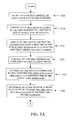
- FIG. 5A is a flowchart illustrating steps for managing information storage among plural disk drives in accordance with an exemplary embodiment of the present invention.
- a switch controller selects among first and second elements, although the switch controller can select among any number of elements.
- Each of the first and second elements comprises a set of disk drives for storing information.
- Elements can include any number of disk drives.
- each disk drive contained in the first and second elements is a SATA disk drive or SAS disk drive, although each disk drive can be any type of disk drive or storage system.
- At least one of the first and second elements is a member of a RAID (redundant array of inexpensive disks, also known as redundant array of independent disks) set.
- the disk drives of any one or combination of elements can be configured as, for example, a RAID set or any other type of disk array system that provides fault tolerance and improved performance.
- each element frame is included in a master frame that contains multiple frame types.
- the master frame types are at least one of an element frame, a control frame, a broadcast frame, a poll frame, a copy frame, a mirror frame or any other type of frame that can be used to manage information storage.
- a master frame can include any combination of frames (including repetition of particular frames), of any type, in any number, in any order or sequence, and of any duration (less than the total duration of the master frame).
- a control frame connects at least one of the plural host interfaces to the switch controller to determine a status.
- the control frame can identify at least one of a sequence and a maximum duration of each frame in the master frame, although the control frame can identify any durational measure of each frame (e.g., actual duration, minimum duration, average duration, etc.).
- a poll frame is a frame during which any number of disk drives communicates with any type of host controller over the plural host interfaces.
- a copy frame is a frame during which information can be copied from one disk drive to one or more other disk drives.
- a mirror frame is a frame during which information received over one of the plural host interfaces is directed by the switch controller to two or more disk drives simultaneously.
- a broadcast frame is a frame during which any type of host controller can communicate with all disk drives using one or more of the plural host interfaces.
- a broadcast frame is a frame during which any one disk drive can communicate with any number of other disk drives.
- each disk drive can be connected to its respective host interface through its respective switch.
- all disk drives of all elements on the same host interface can receive information from a host controller during a broadcast frame.
- FIG. 6 is a flowchart illustrating steps for processing a broadcast frame by a switch controller in accordance with an exemplary embodiment of the present invention.
- the switch controller recognizes the broadcast frame.
- the host controller notifies the switch controller that a broadcast frame is to begin.
- the host controller can issue any type of signal sequence, such as, for example, an interrupt, to the switch controller at the start of a broadcast frame that indicates to the switch controller that a broadcast frame is to begin.
- the signal sequence can indicate the host interfaces over which the host controller is to communicate.
- the broadcast information received by the switch controller is communicated from the host controller to the plural disk drives.
- the switch controller can enable the disk drives on the designated host interfaces and direct the information from the host controller to those enabled disk drives during the broadcast frame.
- each disk drive included in the first element is connected to a different one of plural host interfaces during the element frame of the first element.
- Each of plural host interfaces can be any serial disk drive host interface that can be used for accessing disk drives.
- the switch controller is configurable by at least one of the plural host interfaces.
- a scan controller associates each disk drive of the plural disk drives to one of the plural host interfaces.
- the scan controller can be connected to each switch that is connected to each of the plural disk drives.
- Scan controller can be connected to each switch using any type of connection that is capable of transmitting and receiving information.
- step 515 the switch controller directs information from a first one of the plural host interfaces to a selected disk drive within the first element, although the switch controller can direct information from any of the plural host interfaces to any disk drive in any element.
- a frame controller controls a duration of each frame (e.g., an element frame or any other type of frame) included in the master frame.
- the frame controller also controls a maximum duration of each frame in the master frame, although the frame controller can control any durational measure of any frame in the master frame (e.g., actual duration, minimum duration, average duration, etc.).
- the duration of each frame in the master frame can be, for example, pre-assigned or changed dynamically. Consequently, the frame controller can change the duration of any frame or frames in the master frame.
- the switch controller controls plural switches for associating each disk drive to a different one of the plural host interfaces.
- each of the plural disk drives includes a switch to connect each disk drive to its associated one of the plural host interfaces.
- Each of the switches can be any type of switch capable of satisfying the requirements of each serial interface, in which the serial interfaces can have the same or different requirements.
- a line monitor determines a state of activity of at leastone disk drive in a selected one of the first and second elements.
- the line monitor can determine whether or not the disk drives in an element are quiescent or otherwise idle.
- the line monitor can be a disturbance or idle detector or any other form of circuit for detecting the existence of activity on a connection.
- the line monitor can be connected to each of the plural switches in each of the elements using any type of connection that is capable of transmitting and receiving information.
- the disturbance detector of line monitor can detect the presence of activity.
- a host interface controller using a disk drive interface, communicates between the switch controller and one of the plural disk drives and between the switch controller and one of the plural host interfaces.
- the host interface controller can be any type of device that can receive and transmit information using any host interface protocol for accessing and controlling disk drives. According to exemplary embodiments, communication is performed by
- the disk drive interface can be at least one of a SATA interface and a SAS interface.
- the disk drive interface of the host interface controller for communicating information (e.g., commands and data) through host interface controller can be any interface that can be used for accessing and controlling disk drives.
- the switch controller optionally allocates a disk drive in a third element to replace a disk drive contained in one of the first and second elements.
- the third element comprises plural disk drives for storing information.
- the third element can act as a “spares” element for replacing any disk drive that fails in any element.
- any number of spares elements can be used, with each spares element having any number of disk drives.
- the disk drives of the spares element can be switched into any element at any time by the switch controller.
- the switch controller can replace any disk drive in any element using any disk drive from any other element. Such redundancy provides for uninterrupted operation in case of failure of one or more of the disk drives of an element.
- the switch controller optionally establishes a connection between at least two disk drives of the plural disk drives to copy information between the at least two disk drives.
- the information can be copied between the at least two disk drives during a copy frame.
- the switch controller can connect any disk drive of any element (i.e., the source disk drive) to any number of other disk drives in any other elements (i.e., the destination disk drives).
- the switch controller can send a signal sequence to the source and destination disk drives to initiate the transfer of information from the source to the destination disk drive(s).
- the signal sequence can be any type of signal sequence that is capable of initiating the copying of information, such as, for example, an interrupt, a unique copy-to-copy command, or any other type of signal sequence.
- the copying of information can be carried out autonomously between the source and destination disk drives during the copy frame or while other frames are being processed.
- either the source or destination disk drives can send a signal sequence, for example, an interrupt, to the switch controller to indicate that the copying is completed.
- a connection is optionally established by the switch controller between the first host interface and at least two disk drives of the plural disk drives.
- Each of the at least two disk drives receives the information from the first host interface.
- the mirroring of data to two or more disk drives can occur during a copy frame or a mirror frame.
- the switch controller can switch in or otherwise allocate at least two disk drives (i.e., the slaves) to one of the plural host interfaces (i.e., the master).
- the switch controller can switch in or otherwise allocate at least two disk drives (i.e., the slaves) to one of the plural host interfaces (i.e., the master).
- the switch controller can switch in or otherwise allocate at least two disk drives (i.e., the slaves) to one of the plural host interfaces (i.e., the master).
- the switch controller can switch in or otherwise allocate at least two disk drives (i.e., the slaves) to one of the plural host interfaces (i.e., the master).
- FIG. 7 is a flowchart illustrating steps for controlling frame sequence and frame skipping by a switch controller in accordance with an exemplary embodiment of the present invention.
- a sequence of plural frames in a master frame is controlled by the switch controller.
- the frames in a master frame can be ordered in any sequence and instantiated any number of times. For example, a particular frame can be instantiated multiple times in a master frame if there is a substantial amount of activity occurring during that particular frame and additional processing is required to complete the designated activity, function or process.
- step 710 at least one frame is skipped by the switch controller in the sequence of plural frames in the master frame.
- the line monitor can be used by the switch controller to skip frames in the master frame.
- step 715 the switch controller skips to a next element frame when the line monitor detects an idle condition of at least one disk drive in the first element. However, the switch controller can skip any element frame associated with any element when at least one disk drive in the element is idle.
- the frame controller responds to the line monitor for detecting an idle condition of at least one disk drive in the first element for skipping to a next element frame.
- the line monitor scans or otherwise monitors the disk drives in an element. For example, if the next frame in the master frame is an element frame, then before transitioning to the next (element) frame in the master frame, the line monitor can monitor the next (element) frame in the master frame to determine if the disk drives in that element are idle. If the line monitor detects that, for example, at least one disk drive in a the next element is idle, the line monitor can provide an interrupt or other signal sequence to the switch controller to notify the switch controller that the disk drives in the element are idle. Thereafter, the switch controller can use the frame controller to skip over the element frame to another frame in the master frame.
- all frames in the master frame can be monitored or otherwise processed in parallel to determine, for example, which frames in the master frame can be skipped by the frame controller.
- the line monitor can scan or otherwise monitor the disk drives in all elements to determine which disk drives in which elements are idle. If the line monitor detects that, for example, at least one disk drive in one or more elements is idle, the line monitor can provide an interrupt or other signal sequence to the switch controller to inform the switch controller that the disk drives in those elements are idle. Thereafter, the switch controller can instruct the scan controller to command the frame controller to skip over the element frames associated with those idle elements to another frame in the master frame. By monitoring all frames in the master frame in parallel, the frame controller can skip over any number, combination, or sequence of frames in the master frame.
- the idle monitor can be used by switch controller to force idle the disk drives in an element to transition the element frame to another frame in the master frame without loss of information (e.g., data, commands).
- the switch controller can command the line monitor to issue a signal sequence to the disk drives in an element during an element frame.
- the signal sequence commands the disk drives in the element to discontinue use of their associated host interfaces.
- the signal sequence can be, for example, an interrupt or any form of signal sequence for commanding a disk drive to stop communicating over its respective host interface, for example, a SATA data transfer disconnect.
- the idle monitor can detect the idle condition of at leastone disk drive in the element.
- the line monitor can provide an interrupt or other signal sequence to the switch controller to inform the switch controller that the at least one disk drive in the element is idle. Thereafter, the switch controller can use the frame controller to skip to another frame in the master frame.
- the idle monitor can detect an idle condition of at least one disk drive in next element frame. As discussed previously, if at least one disk drive in the next element frame is idle, the idle monitor can notify the switch controller of this condition. Consequently, once the at least one disk drive in the current element frame has become idle, the switch controller can skip the next element frame to another frame in the master frame. The switch controller can skip any number of element frames in the master frame using such a mechanism. Alternatively, the switch controller can use the notification from the line monitor to instruct the frame controller to alter or otherwise modify the duration of an element frame, for example, to either shorten or lengthen the duration of an element frame depending on the utilization of the disk drives enabled during an element frame.
- FIG. 8 is a flowchart illustrating steps for controlling frame duration and frame termination by a frame controller in accordance with an exemplary embodiment of the present invention.
- a maximum duration of each frame in the master frame is controlled by the frame controller.
- the frame controller can control any measure of the duration of any frame in the master frame (e.g., actual duration, minimum duration, average duration, etc.). For example, if a particular frame is underutilized, the frame controller can assign a shorter frame duration to that particular frame. Alternatively, if a particular frame is over-utilized (e.g., the disk drives in an element are requesting above-average amounts of service during an element frame), the frame controller can assign a longer duration to that particular frame.
- the duration of each frame in the master frame can be, for example, pre-assigned or dynamically changed. Consequently, the frame controller can change the duration of any frame or frames in the master frame.
- an element frame is terminated by the frame controller in response to the scan controller to transition to a next element frame.
- the scan controller is connected to each frame controller using any type of connection that is capable of transmitting and receiving information.
- the end of a frame occurs when the end of a predetermined or dynamically-determined time duration of the frame is reached.
- the switch controller establishes an end of the element frame by using the frame controllers to de-allocate, disable, or otherwise disconnect the corresponding switches on the plural host interfaces to which the disk drives in the element are connected.
- a signal sequence is issued by the switch controller, through the frame controller, to the plural host interfaces and to the disk drives associated with the first element to terminate the element frame associated with the first element.
- the signal sequence can be an interrupt, a command, or any other type of signal sequence that notifies the plural host interfaces and notifies the disk drives associated with the first element to cease, suspend or otherwise interrupt their current action, process, or function so that the element frame can be terminated.
- the frame controller can terminate the element frame.
- one or more host controllers connected to the plural host interfaces can query the switch controller to determine, for example, the status of the disk drives in the next element frame.
- configuration information is stored in one of the first and second elements.
- the configuration information is used to configure at least one of the switch controller and the frame controller.
- configuration information can be any type of information that can be used to configure or control any part or component used to manage information storage among plural disk drives in accordance with exemplary embodiments of the present invention.
- the configuration information can be downloaded or otherwise retrieved by a host controller or the switch controller to configure or otherwise program the switch controller to manage the information storage of the plural disk drives. Once programmed, the switch controller can then access and control all disk drives in all elements.
- the information directed between the selected disk drive within the first element and the first host interface includes a tag for communicating information.
- the tag uniquely identifies an element from other elements, so that information can be communicated between a particular element and the host interfaces.
- the tag can include an identification field for identifying the first element and a command field for command information for the first element.
- the tag can include any type of fields for communicating any type of information.
- the tag can be any type of tag that can be used for differentiating messages between different elements.
- the tag can be a queue tag, such as that used in the SCSI protocol, the SATA command queue tag used in the SATA protocol, frame information structure field of a frame used in the SATA protocol, the switch resource manager field used in the SATA protocol, the route extension field used in the SATA protocol, or any other type of tag.
- Using tags according to exemplary embodiments of the present invention allows information to be communicated between the disk drives of any number of elements and their respective host interfaces, while maintaining a designation of the element associated with the information so that the information is routed correctly.
- each of the plural disk drives can be a set of disk drives, in which each set of disk drives includes a switch controller and a frame controller.
- each set of disk drives can include at least one of a scan controller, a line monitor, and a host interface controller.
- the functions and mechanisms of the individual components (e.g., switch control processor, frame controller, scan controller, line monitor, host interface controller) at each level of sub-element are the same as that described previously.
- Such a replication of functionality at the sub-element level allows each sub-element to be controlled as its own array of disks, using the same command and control procedures described previously.
- the replication of the structure of system 100 for each disk drive in each element can occur to any desired depth of replication.
- the element frame associated with the first element includes plural sub-element frames, in which each sub-element frame is associated with a set of disk drives in the first element.
- each set of disk drives in the sub-element of an element is associated with a sub-element frame.
- the sub-element frame has all the characteristics and features of an element frame.
- the maximum duration of a sub-element frame is less than a maximum duration of the element frame.
- the frame controller e.g., sub-frame controller
- the switch controller e.g., sub-switch controller controls a sequence of each sub-element frame in the element frame.
- each element frame in the master frame can be subdivided into any type of sub-frame, such as a sub-element frame, a sub-control frame, a sub-broadcast frame, a sub-poll frame, a sub-copy frame, or any other type of sub-frame.
- Each type of sub-frame has the same characteristics and features, and is controlled in the same manner, as the corresponding type of (regular) frames discussed previously.
- each element frame can act as a sub-master frame that contains multiple sub-frame types.
- the corresponding element frame can be sub-divided into any desired number of sub-frames (e.g., a sub-element frame divided into sub-sub-element frames, etc.).
- the steps of a computer program as illustrated in FIGS. 5A, 5 B, 6 , 7 , and 8 for managing information storage among plural disk drives can be embodied in any computer-readable medium for use by or in connection with an instruction execution system, apparatus, or device, such as a computer-based system, processor-containing system, or other system that can fetch the instructions from the instruction execution system, apparatus, or device and execute the instructions.
- a “computer-readable medium” can be any means that can contain, store, communicate, propagate, or transport the program for use by or in connection with the instruction execution system, apparatus, or device.
- the computer readable medium can be, for example but not limited to, an electronic, magnetic, optical, electromagnetic, infrared, or semiconductor system, apparatus, device, or propagation medium.
- the computer-readable medium can include the following: an electrical connection having one or more wires, a portable computer diskette, a random access memory (RAM), a read-only memory (ROM), an erasable programmable read-only memory (EPROM or Flash memory), an optical fiber, and a portable compact disc read-only memory (CDROM).
- RAM random access memory
- ROM read-only memory
- EPROM or Flash memory erasable programmable read-only memory
- CDROM portable compact disc read-only memory
Landscapes
- Engineering & Computer Science (AREA)
- Theoretical Computer Science (AREA)
- Physics & Mathematics (AREA)
- General Engineering & Computer Science (AREA)
- General Physics & Mathematics (AREA)
- Human Computer Interaction (AREA)
- Quality & Reliability (AREA)
- Computer Networks & Wireless Communication (AREA)
- Signal Processing For Digital Recording And Reproducing (AREA)
Abstract
Description
Claims (83)
Priority Applications (1)
| Application Number | Priority Date | Filing Date | Title |
|---|---|---|---|
| US10/137,237 US6792486B1 (en) | 2002-04-30 | 2002-04-30 | System and method for managing information storage among plural disk drives |
Applications Claiming Priority (1)
| Application Number | Priority Date | Filing Date | Title |
|---|---|---|---|
| US10/137,237 US6792486B1 (en) | 2002-04-30 | 2002-04-30 | System and method for managing information storage among plural disk drives |
Publications (1)
| Publication Number | Publication Date |
|---|---|
| US6792486B1 true US6792486B1 (en) | 2004-09-14 |
Family
ID=32925422
Family Applications (1)
| Application Number | Title | Priority Date | Filing Date |
|---|---|---|---|
| US10/137,237 Expired - Lifetime US6792486B1 (en) | 2002-04-30 | 2002-04-30 | System and method for managing information storage among plural disk drives |
Country Status (1)
| Country | Link |
|---|---|
| US (1) | US6792486B1 (en) |
Cited By (145)
| Publication number | Priority date | Publication date | Assignee | Title |
|---|---|---|---|---|
| US20030110330A1 (en) * | 2001-12-12 | 2003-06-12 | Fujie Yoshihiro H. | System and method of transferring data from a secondary storage controller to a storage media after failure of a primary storage controller |
| US20030159012A1 (en) * | 2002-02-18 | 2003-08-21 | Yec Co., Ltd. | Back-up system |
| US20030236953A1 (en) * | 2002-06-21 | 2003-12-25 | Compaq Information Technologies Group, L.P. | System and method for providing multi-initiator capability to an ATA drive |
| US20030236952A1 (en) * | 2002-06-21 | 2003-12-25 | Grieff Thomas W. | System and method for providing multi-initiator capability to an ATA drive |
| US20040113662A1 (en) * | 2002-12-11 | 2004-06-17 | Grimsrud Knut S. | Presence indication signal associated with an attachment |
| US20040123027A1 (en) * | 2002-10-03 | 2004-06-24 | Workman Michael Lee | Systems and methods of multiple access paths to single ported storage devices |
| US20050022051A1 (en) * | 2002-09-18 | 2005-01-27 | Netezza Corporation | Disk mirror architecture for database appliance with locally balanced regeneration |
| US20050120264A1 (en) * | 2003-11-28 | 2005-06-02 | Azuma Kano | Disk array system and method for controlling disk array system |
| US20050144268A1 (en) * | 2003-12-08 | 2005-06-30 | Mohammad El-Batal | Managing spare devices on a finite network |
| US20050149672A1 (en) * | 2003-05-22 | 2005-07-07 | Katsuyoshi Suzuki | Disk array apparatus and method for controlling the same |
| US20050182874A1 (en) * | 2003-02-28 | 2005-08-18 | Herz John P. | Disk array controller and system with automated detection and control of both ATA and SCSI disk drives |
| US20060041702A1 (en) * | 2004-08-19 | 2006-02-23 | Greenberger Alan J | Controller apparatus and method for improved data transfer |
| US20060155928A1 (en) * | 2005-01-13 | 2006-07-13 | Yasuyuki Mimatsu | Apparatus and method for managing a plurality of kinds of storage devices |
| US7089448B2 (en) | 2002-09-18 | 2006-08-08 | Netezza Corporation | Disk mirror architecture for database appliance |
| US20060242088A1 (en) * | 2005-04-21 | 2006-10-26 | Masaru Yamamoto | System, method and program for managing information |
| US20080028157A1 (en) * | 2003-01-13 | 2008-01-31 | Steinmetz Joseph H | Global shared memory switch |
| US20080104264A1 (en) * | 2006-11-01 | 2008-05-01 | Duerk Vicky P | Load balancing in a storage system |
| US7423354B2 (en) | 2003-12-25 | 2008-09-09 | Hitachi, Ltd. | Storage system |
| US7457981B2 (en) | 2004-02-04 | 2008-11-25 | Hitachi, Ltd. | Anomaly notification control in disk array |
| US7480765B2 (en) | 2003-05-22 | 2009-01-20 | Hitachi, Ltd. | Storage unit and circuit for shaping communication signal |
| US7739432B1 (en) | 2005-09-02 | 2010-06-15 | Pmc-Sierra, Inc. | Command switching for multiple initiator access to a SATA drive |
| US20110167220A1 (en) * | 2003-02-17 | 2011-07-07 | Hitachi, Ltd. | Storage system for holding a remaining available lifetime of a logical storage region |
| US8127059B1 (en) * | 2005-09-02 | 2012-02-28 | Pmc-Sierra Us, Inc. | Apparatus for interconnecting hosts with storage devices |
| US8879188B1 (en) | 2010-08-23 | 2014-11-04 | Western Digital Technologies, Inc. | Disk drive employing fly height calibration tracks to account for magnetic entropy and thermal decay |
| US8891193B1 (en) | 2013-05-09 | 2014-11-18 | Western Digital Technologies, Inc. | Disk drive calibrating threshold and gain of touchdown sensor |
| US8891341B1 (en) | 2013-03-11 | 2014-11-18 | Western Digital Technologies, Inc. | Energy assisted magnetic recording disk drive using modulated laser light |
| US8902527B1 (en) | 2010-03-22 | 2014-12-02 | Western Digital Technologies, Inc. | Systems and methods for improving sequential data rate performance using sorted data zones |
| US8902529B1 (en) | 2012-11-20 | 2014-12-02 | Western Digital Technologies, Inc. | Dual frequency crystal oscillator |
| US8908311B1 (en) | 2014-01-27 | 2014-12-09 | Western Digital Technologies, Inc. | Data storage device writing a multi-sector codeword in segments over multiple disk revolutions |
| US8909889B1 (en) | 2011-10-10 | 2014-12-09 | Western Digital Technologies, Inc. | Method and apparatus for servicing host commands by a disk drive |
| US8914625B1 (en) | 2009-07-31 | 2014-12-16 | Western Digital Technologies, Inc. | Automatically configuring a web browser file when booting an operating system from a data storage device |
| US8922939B1 (en) | 2013-04-02 | 2014-12-30 | Western Digital Technologies, Inc. | Disk drive generating feed-forward fly height control based on temperature sensitive fly height sensor |
| US8937782B1 (en) | 2012-05-07 | 2015-01-20 | Western Digital Technologies, Inc. | Hard disk drive assembly including a NVSM to store configuration data for controlling disk drive operations |
| US8941941B1 (en) | 2013-02-28 | 2015-01-27 | Western Digital Technologies, Inc. | Disk drive calibrating touchdown sensor |
| US8947812B1 (en) | 2014-03-27 | 2015-02-03 | Western Digital Technologies, Inc. | Data storage device comprising equalizer filter and inter-track interference filter |
| US8949521B1 (en) | 2013-04-10 | 2015-02-03 | Western Digital Technologies, Inc. | Actuator prepositioning for disk drive |
| US8954664B1 (en) | 2010-10-01 | 2015-02-10 | Western Digital Technologies, Inc. | Writing metadata files on a disk |
| US8953277B1 (en) | 2014-06-16 | 2015-02-10 | Western Digital Technologies, Inc. | Data storage device writing tracks on a disk with equal spacing |
| US8953269B1 (en) | 2014-07-18 | 2015-02-10 | Western Digital Technologies, Inc. | Management of data objects in a data object zone |
| US8959281B1 (en) | 2012-11-09 | 2015-02-17 | Western Digital Technologies, Inc. | Data management for a storage device |
| US8958167B1 (en) | 2013-12-23 | 2015-02-17 | Western Digital Technologies, Inc. | Detection of disk surface irregularities in data storage devices |
| US8970978B1 (en) | 2012-10-22 | 2015-03-03 | Western Digital Technologies, Inc. | Disk drive detecting head touchdown by applying DC+AC control signal to fly height actuator |
| US8976633B1 (en) | 2014-04-15 | 2015-03-10 | Western Digital Technologies, Inc. | Data storage device calibrating fly height actuator based on laser power for heat assisted magnetic recording |
| US8988810B1 (en) | 2014-04-16 | 2015-03-24 | Western Digital Technologies, Inc. | Track measurement for data storage device |
| US8988809B1 (en) | 2014-02-18 | 2015-03-24 | Western Digital (Fremont), Llc | Disk recording device for writing a radially coherent reference band by measuring relative timing offsets of reference bursts |
| US8990493B1 (en) | 2011-06-30 | 2015-03-24 | Western Digital Technologies, Inc. | Method and apparatus for performing force unit access writes on a disk |
| US8996839B1 (en) | 2012-01-23 | 2015-03-31 | Western Digital Technologies, Inc. | Data storage device aligning partition to boundary of sector when partition offset correlates with offset of write commands |
| US9001453B1 (en) | 2014-07-18 | 2015-04-07 | Western Digital Technologies, Inc. | Data storage device calibrating fly height actuator based on read mode touchdown resistance of touchdown sensor |
| US9009358B1 (en) | 2008-09-23 | 2015-04-14 | Western Digital Technologies, Inc. | Configuring a data storage device with a parameter file interlocked with configuration code |
| US9013818B1 (en) | 2013-12-06 | 2015-04-21 | Western Digital Technologies, Inc. | Disk drive measuring reader/writer gap by measuring fractional clock cycle over disk radius |
| US9013821B1 (en) | 2014-06-10 | 2015-04-21 | Western Digital Technologies, Inc. | Data storage device employing one-dimensional and two-dimensional channels |
| US9021410B1 (en) | 2013-12-10 | 2015-04-28 | Western Technologies, Inc. | Electronic system with multi-cycle simulation coverage mechanism and method of operation thereof |
| US9025270B1 (en) | 2013-09-17 | 2015-05-05 | Western Digital Technologies, Inc. | Electronic system with current conservation mechanism and method of operation thereof |
| US9025267B1 (en) | 2014-06-09 | 2015-05-05 | Western Digital Technologies, Inc. | Data storage device using branch metric from adjacent track to compensate for inter-track interference |
| US9025421B1 (en) | 2014-10-08 | 2015-05-05 | Western Digital Technologies, Inc. | Data storage device adjusting laser input power to compensate for temperature variations |
| US9047917B1 (en) | 2013-11-26 | 2015-06-02 | Western Digital Technologies, Inc. | Disk drive slider with sense amplifier for coupling to a preamp through a supply/bias line and a read signal line |
| US9049471B2 (en) | 2001-10-17 | 2015-06-02 | Keen Personal Media, Inc. | Personal video recorder for inserting a stored advertisement into a displayed broadcast stream |
| US9053749B1 (en) | 2013-03-15 | 2015-06-09 | Western Digital Technologies, Inc. | Disk drive comprising a per-drive and per-head fly height filter |
| US9053730B1 (en) | 2012-05-11 | 2015-06-09 | Western Digital Technologies, Inc. | Disk drive comprising extended range head proximity sensor |
| US9060420B2 (en) | 2007-11-01 | 2015-06-16 | Western Digitial Technologies, Inc. | Method of manufacturing a double sided flex circuit for a disk drive wherein a first side lead provides an etching mask for a second side lead |
| US9063838B1 (en) | 2012-01-23 | 2015-06-23 | Western Digital Technologies, Inc. | Data storage device shifting data chunks of alignment zone relative to sector boundaries |
| US9064542B1 (en) | 2013-04-08 | 2015-06-23 | Western Digital Technologies, Inc. | Scheduled load of heads to reduce lubricant migration on pole tip and decrease time to ready |
| US9064504B1 (en) | 2014-01-29 | 2015-06-23 | Western Digital Technologies, Inc. | Electronic system with media recovery mechanism and method of operation thereof |
| US9064525B2 (en) | 2013-11-26 | 2015-06-23 | Western Digital Technologies, Inc. | Disk drive comprising laser transmission line optimized for heat assisted magnetic recording |
| US9070406B1 (en) | 2014-03-10 | 2015-06-30 | Western Digital Technologies, Inc. | Disk drive configuring one-dimensional and two-dimensional recording areas based on read element spacing |
| US9076474B1 (en) | 2014-12-23 | 2015-07-07 | Western Digital Technologies, Inc. | Data storage device attenuating thermal decay effect on fly height measurement |
| US9074941B1 (en) | 2013-03-14 | 2015-07-07 | Western Digital Technologies, Inc. | Systems and methods for measuring ambient and laser temperature in heat assisted magnetic recording |
| US9075714B1 (en) | 2014-05-13 | 2015-07-07 | Western Digital Technologies, Inc. | Electronic system with data management mechanism and method of operation thereof |
| US9082458B1 (en) | 2014-03-10 | 2015-07-14 | Western Digital Technologies, Inc. | Data storage device balancing and maximizing quality metric when configuring arial density of each disk surface |
| US9099144B1 (en) | 2013-10-11 | 2015-08-04 | Western Digital Technologies, Inc. | Disk drive evaluating laser performance for heat assisted magnetic recording |
| US9099103B1 (en) | 2014-10-21 | 2015-08-04 | Western Digital Technologies, Inc. | Heat assisted magnetic recording withinterlaced high-power heated and low-power heated tracks |
| US9099134B1 (en) | 2015-01-27 | 2015-08-04 | Western Digital Technologies, Inc. | Data storage device employing multiple jog profiles for a butterfly written disk surface |
| US9117479B1 (en) | 2014-09-24 | 2015-08-25 | Western Digital Technologies, Inc. | Data storage device calibrating laser write power for heat assisted magnetic recording |
| US9117463B1 (en) | 2014-06-23 | 2015-08-25 | Western Digital Technologies, Inc. | Data storage device erasing multiple adjacent data tracks to recover from inter-track interference |
| US9117489B1 (en) | 2014-02-18 | 2015-08-25 | Western Digital Technologies, Inc. | Data storage device screening heads by verifying defects after defect scan |
| US9123370B1 (en) | 2014-04-15 | 2015-09-01 | Western Digital Technologies, Inc. | Data storage device calibrating fly height actuator based on laser power for heat assisted magnetic recording |
| US9123382B1 (en) | 2014-10-28 | 2015-09-01 | Western Digital Technologies, Inc. | Non-volatile caching for sequence of data |
| US9128820B1 (en) | 2012-06-18 | 2015-09-08 | Western Digital Technologies, Inc. | File management among different zones of storage media |
| US9129628B1 (en) | 2014-10-23 | 2015-09-08 | Western Digital Technologies, Inc. | Data management for data storage device with different track density regions |
| US9135205B1 (en) | 2013-05-01 | 2015-09-15 | Western Digital Technologies, Inc. | Data storage assembly for archive cold storage |
| US9153287B1 (en) | 2013-05-13 | 2015-10-06 | Western Digital Technologies, Inc. | Data access for shingled magnetic recording media |
| US9153266B1 (en) | 2014-09-11 | 2015-10-06 | Western Digital Technologies, Inc. | Data storage device measuring laser protrusion fly height profile |
| US9158722B1 (en) | 2011-11-02 | 2015-10-13 | Western Digital Technologies, Inc. | Data storage device to communicate with a host in a SATA or a USB mode |
| US9164694B1 (en) | 2013-06-19 | 2015-10-20 | Western Digital Technologies, Inc. | Data storage device detecting read-before-write conditions and returning configurable return data |
| US9171575B1 (en) | 2014-06-23 | 2015-10-27 | Western Digital Technologies, Inc. | Data storage device detecting media defects by writing opposite polarity test pattern |
| US9183864B1 (en) | 2013-06-13 | 2015-11-10 | Western Digital Technologies, Inc. | Disk drive adjusting closed-loop fly height target based on change in open-loop fly height control signal |
| US9183877B1 (en) | 2015-03-20 | 2015-11-10 | Western Digital Technologies, Inc. | Data storage device comprising two-dimensional data dependent noise whitening filters for two-dimensional recording |
| US9189392B1 (en) | 2011-06-30 | 2015-11-17 | Western Digital Technologies, Inc. | Opportunistic defragmentation during garbage collection |
| US9196302B1 (en) | 2015-03-18 | 2015-11-24 | Western Digital Technologies, Inc. | Electronic system with media maintenance mechanism and method of operation thereof |
| US9214186B1 (en) | 2015-03-23 | 2015-12-15 | Western Digital Technologies, Inc. | Data storage device measuring radial offset between read element and write element |
| US9213493B1 (en) | 2011-12-16 | 2015-12-15 | Western Digital Technologies, Inc. | Sorted serpentine mapping for storage drives |
| US9230605B1 (en) | 2014-12-01 | 2016-01-05 | Western Digital Technologies, Inc. | Data storage device maximizing areal density based on a target quality metric |
| US9230585B1 (en) | 2014-01-31 | 2016-01-05 | Western Digital Technologies, Inc. | Per wedge preheat DFH to improve data storage device performance |
| US9236086B1 (en) | 2014-10-15 | 2016-01-12 | Western Digital Technologies, Inc. | Methods for reducing operational latency of data storage systems |
| US9245556B2 (en) | 2014-03-10 | 2016-01-26 | Western Digital Technologies, Inc. | Disk drive employing multiple read elements to increase radial band for two-dimensional magnetic recording |
| US9245558B1 (en) | 2014-05-09 | 2016-01-26 | Western Digital Technologies, Inc. | Electronic system with data management mechanism and method of operation thereof |
| US9251844B1 (en) | 2014-06-02 | 2016-02-02 | Western Digital Technologies, Inc. | Waterfall method and apparatus for a data storage device read system |
| US9251856B1 (en) | 2014-05-30 | 2016-02-02 | Western Digial Technologies, Inc. | Read failover method and apparatus for a data storage system |
| US9257145B1 (en) | 2013-11-27 | 2016-02-09 | Western Digital Technologies, Inc. | Disk drive measuring down-track spacing of read sensors |
| US9257146B1 (en) | 2014-02-11 | 2016-02-09 | Western Digital Technologies, Inc. | Data storage device comprising sequence detector compensating for inter-track interference |
| US9257143B1 (en) | 2014-12-23 | 2016-02-09 | Western Digital Technologies, Inc. | Precautionary measures for data storage device environmental conditions |
| US9263088B2 (en) | 2014-03-21 | 2016-02-16 | Western Digital Technologies, Inc. | Data management for a data storage device using a last resort zone |
| US9269393B1 (en) | 2014-12-08 | 2016-02-23 | Western Digital Technologies, Inc. | Electronic system with data refresh mechanism and method of operation thereof |
| US9268499B1 (en) | 2010-08-13 | 2016-02-23 | Western Digital Technologies, Inc. | Hybrid drive migrating high workload data from disk to non-volatile semiconductor memory |
| US9268649B1 (en) | 2011-06-23 | 2016-02-23 | Western Digital Technologies, Inc. | Disk drive with recent write streams list for data refresh determination |
| US9281009B1 (en) | 2014-12-18 | 2016-03-08 | Western Digital Technologies, Inc. | Data storage device employing variable size interleave written track segments |
| US9311939B1 (en) | 2014-12-23 | 2016-04-12 | Western Digital Technologies, Inc. | Write-through media caching |
| US9318137B1 (en) | 2015-03-13 | 2016-04-19 | Western Digital Technologies, Inc. | Data storage device executing retry operation by buffering signal samples at different radial offsets |
| US9330715B1 (en) | 2010-03-22 | 2016-05-03 | Western Digital Technologies, Inc. | Mapping of shingled magnetic recording media |
| US9355666B1 (en) | 2013-09-30 | 2016-05-31 | Western Digital Technologies, Inc. | Disk drive measuring stroke difference between heads by detecting a difference between ramp contact |
| US9361938B1 (en) | 2015-04-16 | 2016-06-07 | Western Digital Technologies, Inc. | Disk defect management for a data storage device |
| US9368131B1 (en) | 2015-04-03 | 2016-06-14 | Western Digital (Fremont), Llc | Data storage device employing mirrored cross-track profiles for top and bottom disk surfaces |
| US9368132B1 (en) | 2015-09-04 | 2016-06-14 | Western Digital Technologies, Inc. | Data storage device employing differential write data signal and differential write pattern signal |
| US9383923B1 (en) | 2012-10-18 | 2016-07-05 | Western Digital Technologies, Inc. | Write pointer management for a disk drive |
| US9401165B1 (en) | 2014-05-05 | 2016-07-26 | Western Digital Technologies, Inc. | Method and system to monitor magnetic head loading and unloading stability for a data storage system |
| US9417628B2 (en) | 2013-03-13 | 2016-08-16 | Western Digital Technologies, Inc. | Production failure analysis system |
| US9424864B2 (en) | 2014-07-02 | 2016-08-23 | Western Digital Technologies, Inc. | Data management for a data storage device with zone relocation |
| US9437242B1 (en) | 2015-09-14 | 2016-09-06 | Western Digital Technologies, Inc. | Data storage device employing different frequency preambles in adjacent data tracks |
| US9466321B1 (en) | 2015-06-05 | 2016-10-11 | Western Digital Technologies, Inc. | Angular position tracking of data accesses to mitigate risk of data loss |
| US9466318B2 (en) | 2014-12-24 | 2016-10-11 | Western Digital Technologies, Inc. | Allowing fast data zone switches on data storage devices |
| US9472219B1 (en) | 2015-05-01 | 2016-10-18 | Western Digital Technologies, Inc. | Data storage device calibrating parameter for heat assisted magnetic recording |
| US9502068B1 (en) | 2015-04-08 | 2016-11-22 | Western Digital Technologies, Inc. | Data storage device updating laser power during non-write mode for heat assisted magnetic recording |
| US9501393B2 (en) | 2014-01-27 | 2016-11-22 | Western Digital Technologies, Inc. | Data storage system garbage collection based on at least one attribute |
| US9588898B1 (en) | 2015-06-02 | 2017-03-07 | Western Digital Technologies, Inc. | Fullness control for media-based cache operating in a steady state |
| US9600205B1 (en) | 2014-09-22 | 2017-03-21 | Western Digital Technologies, Inc. | Power aware power safe write buffer |
| US9632711B1 (en) | 2014-04-07 | 2017-04-25 | Western Digital Technologies, Inc. | Processing flush requests by utilizing storage system write notifications |
| US9639287B1 (en) | 2015-06-29 | 2017-05-02 | Western Digital Technologies, Inc. | Write command reporting |
| US9645752B1 (en) | 2014-04-07 | 2017-05-09 | Western Digital Technologies, Inc. | Identification of data committed to non-volatile memory by use of notification commands |
| US9672107B1 (en) | 2015-02-11 | 2017-06-06 | Western Digital Technologies, Inc. | Data protection for a data storage device |
| US9747928B1 (en) | 2014-09-25 | 2017-08-29 | Western Digital Technologies, Inc. | Data storage device modifying write operation when a laser mode hop is detected |
| US9761273B1 (en) | 2015-11-03 | 2017-09-12 | Western Digital Technologies, Inc. | Data storage device encoding and interleaving codewords to improve trellis sequence detection |
| US9842617B1 (en) | 2015-06-29 | 2017-12-12 | Western Digital Technologies, Inc. | Electronic system with head management mechanism and method of operation thereof |
| US9842622B1 (en) | 2014-12-23 | 2017-12-12 | Western Digital Technologies, Inc. | Data storage device having improved read failure tolerance |
| US9864529B1 (en) | 2014-01-27 | 2018-01-09 | Western Digital Technologies, Inc. | Host compatibility for host managed storage media |
| US9870281B1 (en) | 2015-03-20 | 2018-01-16 | Western Digital Technologies, Inc. | Power loss mitigation for data storage device |
| US9875055B1 (en) | 2014-08-04 | 2018-01-23 | Western Digital Technologies, Inc. | Check-pointing of metadata |
| US9916616B2 (en) | 2014-03-31 | 2018-03-13 | Western Digital Technologies, Inc. | Inventory management system using incremental capacity formats |
| US9933955B1 (en) | 2015-03-05 | 2018-04-03 | Western Digital Technologies, Inc. | Power safe write buffer for data storage device |
| US9952950B1 (en) | 2014-09-08 | 2018-04-24 | Western Digital Technologies, Inc. | Data management in RAID environment |
| US9959052B1 (en) | 2015-09-17 | 2018-05-01 | Western Digital Technologies, Inc. | Media based cache for data storage device |
| US10056920B1 (en) | 2015-11-03 | 2018-08-21 | Western Digital Technologies, Inc. | Data storage device encoding and interleaving codewords to improve trellis sequence detection |
| US10063257B1 (en) | 2015-11-03 | 2018-08-28 | Western Digital Technologies, Inc. | Data storage device encoding and interleaving codewords to improve trellis sequence detection |
| US10282096B1 (en) | 2014-12-17 | 2019-05-07 | Western Digital Technologies, Inc. | Identification of data with predetermined data pattern |
| US10282371B1 (en) | 2014-12-02 | 2019-05-07 | Western Digital Technologies, Inc. | Object storage device with probabilistic data structure |
| US10365836B1 (en) | 2015-01-27 | 2019-07-30 | Western Digital Technologies, Inc. | Electronic system with declustered data protection by parity based on reliability and method of operation thereof |
Citations (8)
| Publication number | Priority date | Publication date | Assignee | Title |
|---|---|---|---|---|
| US5243581A (en) * | 1990-07-23 | 1993-09-07 | Matsushita Electric Industrial Co., Ltd. | Data recording/reproducing apparatus having plural optical disk drives operating in parallel |
| US5603066A (en) | 1994-03-01 | 1997-02-11 | Adaptec, Inc. | Method of flagging the completion of a second command before the completion of a first command from the same initiator in a SCSI controller |
| US5603062A (en) * | 1992-11-11 | 1997-02-11 | Hitachi, Ltd. | System for controlling data flow between plurality of host interfaces and drive interfaces using controller for select unoccupied interfaces after preparation of read/write operation is complete |
| US5950230A (en) | 1997-05-28 | 1999-09-07 | International Business Machines Corporation | RAID array configuration synchronization at power on |
| US6343324B1 (en) * | 1999-09-13 | 2002-01-29 | International Business Machines Corporation | Method and system for controlling access share storage devices in a network environment by configuring host-to-volume mapping data structures in the controller memory for granting and denying access to the devices |
| US6513102B2 (en) * | 1998-03-12 | 2003-01-28 | Emc Corporation | Internal copy for a storage controller |
| US6542961B1 (en) * | 1998-12-22 | 2003-04-01 | Hitachi, Ltd. | Disk storage system including a switch |
| US6647458B1 (en) * | 2000-04-04 | 2003-11-11 | Emc Corporation | Benchmark tool write analysis for a mass storage system |
-
2002
- 2002-04-30 US US10/137,237 patent/US6792486B1/en not_active Expired - Lifetime
Patent Citations (9)
| Publication number | Priority date | Publication date | Assignee | Title |
|---|---|---|---|---|
| US5243581A (en) * | 1990-07-23 | 1993-09-07 | Matsushita Electric Industrial Co., Ltd. | Data recording/reproducing apparatus having plural optical disk drives operating in parallel |
| US5603062A (en) * | 1992-11-11 | 1997-02-11 | Hitachi, Ltd. | System for controlling data flow between plurality of host interfaces and drive interfaces using controller for select unoccupied interfaces after preparation of read/write operation is complete |
| US5603066A (en) | 1994-03-01 | 1997-02-11 | Adaptec, Inc. | Method of flagging the completion of a second command before the completion of a first command from the same initiator in a SCSI controller |
| US5781803A (en) | 1994-03-01 | 1998-07-14 | Adaptec, Inc. | System for storing initiator, queue tag and logical block information, disconnecting from target if command is not auto transfer, reconnecting and performing data transfer |
| US5950230A (en) | 1997-05-28 | 1999-09-07 | International Business Machines Corporation | RAID array configuration synchronization at power on |
| US6513102B2 (en) * | 1998-03-12 | 2003-01-28 | Emc Corporation | Internal copy for a storage controller |
| US6542961B1 (en) * | 1998-12-22 | 2003-04-01 | Hitachi, Ltd. | Disk storage system including a switch |
| US6343324B1 (en) * | 1999-09-13 | 2002-01-29 | International Business Machines Corporation | Method and system for controlling access share storage devices in a network environment by configuring host-to-volume mapping data structures in the controller memory for granting and denying access to the devices |
| US6647458B1 (en) * | 2000-04-04 | 2003-11-11 | Emc Corporation | Benchmark tool write analysis for a mass storage system |
Cited By (191)
| Publication number | Priority date | Publication date | Assignee | Title |
|---|---|---|---|---|
| US9049471B2 (en) | 2001-10-17 | 2015-06-02 | Keen Personal Media, Inc. | Personal video recorder for inserting a stored advertisement into a displayed broadcast stream |
| US6915381B2 (en) * | 2001-12-12 | 2005-07-05 | International Business Machines Corporation | System and method for transferring data from a secondary storage controller to a storage media after failure of a primary storage controller |
| US20030110330A1 (en) * | 2001-12-12 | 2003-06-12 | Fujie Yoshihiro H. | System and method of transferring data from a secondary storage controller to a storage media after failure of a primary storage controller |
| US20030159012A1 (en) * | 2002-02-18 | 2003-08-21 | Yec Co., Ltd. | Back-up system |
| US6961813B2 (en) * | 2002-06-21 | 2005-11-01 | Hewlett-Packard Development Company, L.P. | System and method for providing multi-initiator capability to an ATA drive |
| US6948036B2 (en) * | 2002-06-21 | 2005-09-20 | Hewlett-Packard Development Company, L.P. | System and method for providing multi-initiator capability to an ATA drive |
| US20030236952A1 (en) * | 2002-06-21 | 2003-12-25 | Grieff Thomas W. | System and method for providing multi-initiator capability to an ATA drive |
| US20030236953A1 (en) * | 2002-06-21 | 2003-12-25 | Compaq Information Technologies Group, L.P. | System and method for providing multi-initiator capability to an ATA drive |
| US7337351B2 (en) | 2002-09-18 | 2008-02-26 | Netezza Corporation | Disk mirror architecture for database appliance with locally balanced regeneration |
| US20050022051A1 (en) * | 2002-09-18 | 2005-01-27 | Netezza Corporation | Disk mirror architecture for database appliance with locally balanced regeneration |
| US7089448B2 (en) | 2002-09-18 | 2006-08-08 | Netezza Corporation | Disk mirror architecture for database appliance |
| US20050149641A1 (en) * | 2002-10-03 | 2005-07-07 | Workman Michael L. | Methods and data storage subsystems of controlling serial ATA storage devices |
| US20050149637A1 (en) * | 2002-10-03 | 2005-07-07 | Fox Douglas J. | Methods of restoring operation of serial ATA storage devices |
| US20050149650A1 (en) * | 2002-10-03 | 2005-07-07 | Workman Michael L. | Data storage systems for assigning control of serial ATA storage devices |
| US20040123027A1 (en) * | 2002-10-03 | 2004-06-24 | Workman Michael Lee | Systems and methods of multiple access paths to single ported storage devices |
| US20040113662A1 (en) * | 2002-12-11 | 2004-06-17 | Grimsrud Knut S. | Presence indication signal associated with an attachment |
| US7113003B2 (en) * | 2002-12-11 | 2006-09-26 | Intel Corporation | Presence indication signal associated with an attachment |
| US20080028157A1 (en) * | 2003-01-13 | 2008-01-31 | Steinmetz Joseph H | Global shared memory switch |
| US8370572B2 (en) | 2003-02-17 | 2013-02-05 | Hitachi, Ltd. | Storage system for holding a remaining available lifetime of a logical storage region |
| US20110167220A1 (en) * | 2003-02-17 | 2011-07-07 | Hitachi, Ltd. | Storage system for holding a remaining available lifetime of a logical storage region |
| US20050182874A1 (en) * | 2003-02-28 | 2005-08-18 | Herz John P. | Disk array controller and system with automated detection and control of both ATA and SCSI disk drives |
| US8429342B2 (en) | 2003-05-22 | 2013-04-23 | Hitachi, Ltd. | Drive apparatus and method for controlling the same |
| US7080201B2 (en) | 2003-05-22 | 2006-07-18 | Hitachi, Ltd. | Disk array apparatus and method for controlling the same |
| US8151046B2 (en) | 2003-05-22 | 2012-04-03 | Hitachi, Ltd. | Disk array apparatus and method for controlling the same |
| US8200898B2 (en) | 2003-05-22 | 2012-06-12 | Hitachi, Ltd. | Storage apparatus and method for controlling the same |
| US7685362B2 (en) | 2003-05-22 | 2010-03-23 | Hitachi, Ltd. | Storage unit and circuit for shaping communication signal |
| US7587548B2 (en) | 2003-05-22 | 2009-09-08 | Hitachi, Ltd. | Disk array apparatus and method for controlling the same |
| US20090150609A1 (en) * | 2003-05-22 | 2009-06-11 | Katsuyoshi Suzuki | Disk array apparatus and method for controlling the same |
| US7461203B2 (en) | 2003-05-22 | 2008-12-02 | Hitachi, Ltd. | Disk array apparatus and method for controlling the same |
| US20050149672A1 (en) * | 2003-05-22 | 2005-07-07 | Katsuyoshi Suzuki | Disk array apparatus and method for controlling the same |
| US7523258B2 (en) | 2003-05-22 | 2009-04-21 | Hitachi, Ltd. | Disk array apparatus and method for controlling the same |
| US7480765B2 (en) | 2003-05-22 | 2009-01-20 | Hitachi, Ltd. | Storage unit and circuit for shaping communication signal |
| US7453774B2 (en) | 2003-11-28 | 2008-11-18 | Hitachi, Ltd. | Disk array system |
| US7203135B2 (en) | 2003-11-28 | 2007-04-10 | Hitachi, Ltd. | Disk array system and method for controlling disk array system |
| US7057981B2 (en) | 2003-11-28 | 2006-06-06 | Hitachi, Ltd. | Disk array system and method for controlling disk array system |
| US7447121B2 (en) | 2003-11-28 | 2008-11-04 | Hitachi, Ltd. | Disk array system |
| US8468300B2 (en) | 2003-11-28 | 2013-06-18 | Hitachi, Ltd. | Storage system having plural controllers and an expansion housing with drive units |
| US7200074B2 (en) | 2003-11-28 | 2007-04-03 | Hitachi, Ltd. | Disk array system and method for controlling disk array system |
| US20050120264A1 (en) * | 2003-11-28 | 2005-06-02 | Azuma Kano | Disk array system and method for controlling disk array system |
| US7865665B2 (en) | 2003-11-28 | 2011-01-04 | Hitachi, Ltd. | Storage system for checking data coincidence between a cache memory and a disk drive |
| US20050144268A1 (en) * | 2003-12-08 | 2005-06-30 | Mohammad El-Batal | Managing spare devices on a finite network |
| US7671485B2 (en) | 2003-12-25 | 2010-03-02 | Hitachi, Ltd. | Storage system |
| US7423354B2 (en) | 2003-12-25 | 2008-09-09 | Hitachi, Ltd. | Storage system |
| US7475283B2 (en) | 2004-02-04 | 2009-01-06 | Hitachi, Ltd. | Anomaly notification control in disk array |
| US8365013B2 (en) | 2004-02-04 | 2013-01-29 | Hitachi, Ltd. | Anomaly notification control in disk array |
| US7823010B2 (en) | 2004-02-04 | 2010-10-26 | Hitachi, Ltd. | Anomaly notification control in disk array |
| US7457981B2 (en) | 2004-02-04 | 2008-11-25 | Hitachi, Ltd. | Anomaly notification control in disk array |
| US8015442B2 (en) | 2004-02-04 | 2011-09-06 | Hitachi, Ltd. | Anomaly notification control in disk array |
| US7284082B2 (en) * | 2004-08-19 | 2007-10-16 | Lsi Corporation | Controller apparatus and method for improved data transfer |
| US20060041702A1 (en) * | 2004-08-19 | 2006-02-23 | Greenberger Alan J | Controller apparatus and method for improved data transfer |
| US7546413B2 (en) | 2005-01-13 | 2009-06-09 | Hitachi, Ltd. | Apparatus and method for managing a plurality of kinds of storage devices |
| US8046536B2 (en) | 2005-01-13 | 2011-10-25 | Hitachi, Ltd. | Apparatus and method for managing a plurality of kinds of storage devices |
| US8190818B2 (en) | 2005-01-13 | 2012-05-29 | Hitachi, Ltd. | Apparatus and method for managing a plurality of kinds of storage devices |
| US20060155928A1 (en) * | 2005-01-13 | 2006-07-13 | Yasuyuki Mimatsu | Apparatus and method for managing a plurality of kinds of storage devices |
| US7308534B2 (en) | 2005-01-13 | 2007-12-11 | Hitachi, Ltd. | Apparatus and method for managing a plurality of kinds of storage devices |
| US20060242088A1 (en) * | 2005-04-21 | 2006-10-26 | Masaru Yamamoto | System, method and program for managing information |
| US8327150B2 (en) * | 2005-04-21 | 2012-12-04 | International Business Machines Corporation | System, method and program for managing information |
| US7739432B1 (en) | 2005-09-02 | 2010-06-15 | Pmc-Sierra, Inc. | Command switching for multiple initiator access to a SATA drive |
| US8127059B1 (en) * | 2005-09-02 | 2012-02-28 | Pmc-Sierra Us, Inc. | Apparatus for interconnecting hosts with storage devices |
| US8447872B2 (en) * | 2006-11-01 | 2013-05-21 | Intel Corporation | Load balancing in a storage system |
| US20080104264A1 (en) * | 2006-11-01 | 2008-05-01 | Duerk Vicky P | Load balancing in a storage system |
| US9060420B2 (en) | 2007-11-01 | 2015-06-16 | Western Digitial Technologies, Inc. | Method of manufacturing a double sided flex circuit for a disk drive wherein a first side lead provides an etching mask for a second side lead |
| US9009358B1 (en) | 2008-09-23 | 2015-04-14 | Western Digital Technologies, Inc. | Configuring a data storage device with a parameter file interlocked with configuration code |
| US8914625B1 (en) | 2009-07-31 | 2014-12-16 | Western Digital Technologies, Inc. | Automatically configuring a web browser file when booting an operating system from a data storage device |
| US9330715B1 (en) | 2010-03-22 | 2016-05-03 | Western Digital Technologies, Inc. | Mapping of shingled magnetic recording media |
| US8902527B1 (en) | 2010-03-22 | 2014-12-02 | Western Digital Technologies, Inc. | Systems and methods for improving sequential data rate performance using sorted data zones |
| US9268499B1 (en) | 2010-08-13 | 2016-02-23 | Western Digital Technologies, Inc. | Hybrid drive migrating high workload data from disk to non-volatile semiconductor memory |
| US8879188B1 (en) | 2010-08-23 | 2014-11-04 | Western Digital Technologies, Inc. | Disk drive employing fly height calibration tracks to account for magnetic entropy and thermal decay |
| US8954664B1 (en) | 2010-10-01 | 2015-02-10 | Western Digital Technologies, Inc. | Writing metadata files on a disk |
| US9268649B1 (en) | 2011-06-23 | 2016-02-23 | Western Digital Technologies, Inc. | Disk drive with recent write streams list for data refresh determination |
| US9189392B1 (en) | 2011-06-30 | 2015-11-17 | Western Digital Technologies, Inc. | Opportunistic defragmentation during garbage collection |
| US8990493B1 (en) | 2011-06-30 | 2015-03-24 | Western Digital Technologies, Inc. | Method and apparatus for performing force unit access writes on a disk |
| US8909889B1 (en) | 2011-10-10 | 2014-12-09 | Western Digital Technologies, Inc. | Method and apparatus for servicing host commands by a disk drive |
| US9158722B1 (en) | 2011-11-02 | 2015-10-13 | Western Digital Technologies, Inc. | Data storage device to communicate with a host in a SATA or a USB mode |
| US9213493B1 (en) | 2011-12-16 | 2015-12-15 | Western Digital Technologies, Inc. | Sorted serpentine mapping for storage drives |
| US8996839B1 (en) | 2012-01-23 | 2015-03-31 | Western Digital Technologies, Inc. | Data storage device aligning partition to boundary of sector when partition offset correlates with offset of write commands |
| US9063838B1 (en) | 2012-01-23 | 2015-06-23 | Western Digital Technologies, Inc. | Data storage device shifting data chunks of alignment zone relative to sector boundaries |
| US8937782B1 (en) | 2012-05-07 | 2015-01-20 | Western Digital Technologies, Inc. | Hard disk drive assembly including a NVSM to store configuration data for controlling disk drive operations |
| US9053730B1 (en) | 2012-05-11 | 2015-06-09 | Western Digital Technologies, Inc. | Disk drive comprising extended range head proximity sensor |
| US9477681B2 (en) | 2012-06-18 | 2016-10-25 | Western Digital Technologies, Inc. | File management among different zones of storage media |
| US9128820B1 (en) | 2012-06-18 | 2015-09-08 | Western Digital Technologies, Inc. | File management among different zones of storage media |
| US9383923B1 (en) | 2012-10-18 | 2016-07-05 | Western Digital Technologies, Inc. | Write pointer management for a disk drive |
| US8970978B1 (en) | 2012-10-22 | 2015-03-03 | Western Digital Technologies, Inc. | Disk drive detecting head touchdown by applying DC+AC control signal to fly height actuator |
| US8959281B1 (en) | 2012-11-09 | 2015-02-17 | Western Digital Technologies, Inc. | Data management for a storage device |
| US8902529B1 (en) | 2012-11-20 | 2014-12-02 | Western Digital Technologies, Inc. | Dual frequency crystal oscillator |
| US8941941B1 (en) | 2013-02-28 | 2015-01-27 | Western Digital Technologies, Inc. | Disk drive calibrating touchdown sensor |
| US8891341B1 (en) | 2013-03-11 | 2014-11-18 | Western Digital Technologies, Inc. | Energy assisted magnetic recording disk drive using modulated laser light |
| US9417628B2 (en) | 2013-03-13 | 2016-08-16 | Western Digital Technologies, Inc. | Production failure analysis system |
| US9074941B1 (en) | 2013-03-14 | 2015-07-07 | Western Digital Technologies, Inc. | Systems and methods for measuring ambient and laser temperature in heat assisted magnetic recording |
| US9053749B1 (en) | 2013-03-15 | 2015-06-09 | Western Digital Technologies, Inc. | Disk drive comprising a per-drive and per-head fly height filter |
| US8922939B1 (en) | 2013-04-02 | 2014-12-30 | Western Digital Technologies, Inc. | Disk drive generating feed-forward fly height control based on temperature sensitive fly height sensor |
| US9064542B1 (en) | 2013-04-08 | 2015-06-23 | Western Digital Technologies, Inc. | Scheduled load of heads to reduce lubricant migration on pole tip and decrease time to ready |
| US8949521B1 (en) | 2013-04-10 | 2015-02-03 | Western Digital Technologies, Inc. | Actuator prepositioning for disk drive |
| US9135205B1 (en) | 2013-05-01 | 2015-09-15 | Western Digital Technologies, Inc. | Data storage assembly for archive cold storage |
| US8891193B1 (en) | 2013-05-09 | 2014-11-18 | Western Digital Technologies, Inc. | Disk drive calibrating threshold and gain of touchdown sensor |
| US9153287B1 (en) | 2013-05-13 | 2015-10-06 | Western Digital Technologies, Inc. | Data access for shingled magnetic recording media |
| US9183864B1 (en) | 2013-06-13 | 2015-11-10 | Western Digital Technologies, Inc. | Disk drive adjusting closed-loop fly height target based on change in open-loop fly height control signal |
| US9164694B1 (en) | 2013-06-19 | 2015-10-20 | Western Digital Technologies, Inc. | Data storage device detecting read-before-write conditions and returning configurable return data |
| US9025270B1 (en) | 2013-09-17 | 2015-05-05 | Western Digital Technologies, Inc. | Electronic system with current conservation mechanism and method of operation thereof |
| US9355666B1 (en) | 2013-09-30 | 2016-05-31 | Western Digital Technologies, Inc. | Disk drive measuring stroke difference between heads by detecting a difference between ramp contact |
| US9099144B1 (en) | 2013-10-11 | 2015-08-04 | Western Digital Technologies, Inc. | Disk drive evaluating laser performance for heat assisted magnetic recording |
| US9047917B1 (en) | 2013-11-26 | 2015-06-02 | Western Digital Technologies, Inc. | Disk drive slider with sense amplifier for coupling to a preamp through a supply/bias line and a read signal line |
| US9299371B1 (en) | 2013-11-26 | 2016-03-29 | Western Digital Technologies, Inc. | Disk drive slider with sense amplifier for coupling to a preamp through a supply/bias line and a read signal line |
| US9064525B2 (en) | 2013-11-26 | 2015-06-23 | Western Digital Technologies, Inc. | Disk drive comprising laser transmission line optimized for heat assisted magnetic recording |
| US9257145B1 (en) | 2013-11-27 | 2016-02-09 | Western Digital Technologies, Inc. | Disk drive measuring down-track spacing of read sensors |
| US9013818B1 (en) | 2013-12-06 | 2015-04-21 | Western Digital Technologies, Inc. | Disk drive measuring reader/writer gap by measuring fractional clock cycle over disk radius |
| US9021410B1 (en) | 2013-12-10 | 2015-04-28 | Western Technologies, Inc. | Electronic system with multi-cycle simulation coverage mechanism and method of operation thereof |
| US8958167B1 (en) | 2013-12-23 | 2015-02-17 | Western Digital Technologies, Inc. | Detection of disk surface irregularities in data storage devices |
| US10282130B2 (en) | 2014-01-27 | 2019-05-07 | Western Digital Technologies, Inc. | Coherency of data in data relocation |
| US8908311B1 (en) | 2014-01-27 | 2014-12-09 | Western Digital Technologies, Inc. | Data storage device writing a multi-sector codeword in segments over multiple disk revolutions |
| US9864529B1 (en) | 2014-01-27 | 2018-01-09 | Western Digital Technologies, Inc. | Host compatibility for host managed storage media |
| US9501393B2 (en) | 2014-01-27 | 2016-11-22 | Western Digital Technologies, Inc. | Data storage system garbage collection based on at least one attribute |
| US9064504B1 (en) | 2014-01-29 | 2015-06-23 | Western Digital Technologies, Inc. | Electronic system with media recovery mechanism and method of operation thereof |
| US9230585B1 (en) | 2014-01-31 | 2016-01-05 | Western Digital Technologies, Inc. | Per wedge preheat DFH to improve data storage device performance |
| US9257146B1 (en) | 2014-02-11 | 2016-02-09 | Western Digital Technologies, Inc. | Data storage device comprising sequence detector compensating for inter-track interference |
| US8988809B1 (en) | 2014-02-18 | 2015-03-24 | Western Digital (Fremont), Llc | Disk recording device for writing a radially coherent reference band by measuring relative timing offsets of reference bursts |
| US9117489B1 (en) | 2014-02-18 | 2015-08-25 | Western Digital Technologies, Inc. | Data storage device screening heads by verifying defects after defect scan |
| US9245556B2 (en) | 2014-03-10 | 2016-01-26 | Western Digital Technologies, Inc. | Disk drive employing multiple read elements to increase radial band for two-dimensional magnetic recording |
| US9070406B1 (en) | 2014-03-10 | 2015-06-30 | Western Digital Technologies, Inc. | Disk drive configuring one-dimensional and two-dimensional recording areas based on read element spacing |
| US9082458B1 (en) | 2014-03-10 | 2015-07-14 | Western Digital Technologies, Inc. | Data storage device balancing and maximizing quality metric when configuring arial density of each disk surface |
| US9263088B2 (en) | 2014-03-21 | 2016-02-16 | Western Digital Technologies, Inc. | Data management for a data storage device using a last resort zone |
| US8947812B1 (en) | 2014-03-27 | 2015-02-03 | Western Digital Technologies, Inc. | Data storage device comprising equalizer filter and inter-track interference filter |
| US9916616B2 (en) | 2014-03-31 | 2018-03-13 | Western Digital Technologies, Inc. | Inventory management system using incremental capacity formats |
| US9632711B1 (en) | 2014-04-07 | 2017-04-25 | Western Digital Technologies, Inc. | Processing flush requests by utilizing storage system write notifications |
| US9645752B1 (en) | 2014-04-07 | 2017-05-09 | Western Digital Technologies, Inc. | Identification of data committed to non-volatile memory by use of notification commands |
| US10162534B1 (en) | 2014-04-07 | 2018-12-25 | Western Digital Technologies, Inc. | Ordering commitment of data from a data cache to nonvolatile memory using ordering commands |
| US8976633B1 (en) | 2014-04-15 | 2015-03-10 | Western Digital Technologies, Inc. | Data storage device calibrating fly height actuator based on laser power for heat assisted magnetic recording |
| US9123370B1 (en) | 2014-04-15 | 2015-09-01 | Western Digital Technologies, Inc. | Data storage device calibrating fly height actuator based on laser power for heat assisted magnetic recording |
| US8988810B1 (en) | 2014-04-16 | 2015-03-24 | Western Digital Technologies, Inc. | Track measurement for data storage device |
| US9401165B1 (en) | 2014-05-05 | 2016-07-26 | Western Digital Technologies, Inc. | Method and system to monitor magnetic head loading and unloading stability for a data storage system |
| US9245558B1 (en) | 2014-05-09 | 2016-01-26 | Western Digital Technologies, Inc. | Electronic system with data management mechanism and method of operation thereof |
| US9075714B1 (en) | 2014-05-13 | 2015-07-07 | Western Digital Technologies, Inc. | Electronic system with data management mechanism and method of operation thereof |
| US9251856B1 (en) | 2014-05-30 | 2016-02-02 | Western Digial Technologies, Inc. | Read failover method and apparatus for a data storage system |
| US9251844B1 (en) | 2014-06-02 | 2016-02-02 | Western Digital Technologies, Inc. | Waterfall method and apparatus for a data storage device read system |
| US9025267B1 (en) | 2014-06-09 | 2015-05-05 | Western Digital Technologies, Inc. | Data storage device using branch metric from adjacent track to compensate for inter-track interference |
| US9013821B1 (en) | 2014-06-10 | 2015-04-21 | Western Digital Technologies, Inc. | Data storage device employing one-dimensional and two-dimensional channels |
| US8953277B1 (en) | 2014-06-16 | 2015-02-10 | Western Digital Technologies, Inc. | Data storage device writing tracks on a disk with equal spacing |
| US9171575B1 (en) | 2014-06-23 | 2015-10-27 | Western Digital Technologies, Inc. | Data storage device detecting media defects by writing opposite polarity test pattern |
| US9117463B1 (en) | 2014-06-23 | 2015-08-25 | Western Digital Technologies, Inc. | Data storage device erasing multiple adjacent data tracks to recover from inter-track interference |
| US9424864B2 (en) | 2014-07-02 | 2016-08-23 | Western Digital Technologies, Inc. | Data management for a data storage device with zone relocation |
| US8953269B1 (en) | 2014-07-18 | 2015-02-10 | Western Digital Technologies, Inc. | Management of data objects in a data object zone |
| US9001453B1 (en) | 2014-07-18 | 2015-04-07 | Western Digital Technologies, Inc. | Data storage device calibrating fly height actuator based on read mode touchdown resistance of touchdown sensor |
| US9875055B1 (en) | 2014-08-04 | 2018-01-23 | Western Digital Technologies, Inc. | Check-pointing of metadata |
| US10572358B1 (en) | 2014-09-08 | 2020-02-25 | Western Digital Technologies, Inc. | Data management in RAID environment |
| US9952950B1 (en) | 2014-09-08 | 2018-04-24 | Western Digital Technologies, Inc. | Data management in RAID environment |
| US9153266B1 (en) | 2014-09-11 | 2015-10-06 | Western Digital Technologies, Inc. | Data storage device measuring laser protrusion fly height profile |
| US9600205B1 (en) | 2014-09-22 | 2017-03-21 | Western Digital Technologies, Inc. | Power aware power safe write buffer |
| US9117479B1 (en) | 2014-09-24 | 2015-08-25 | Western Digital Technologies, Inc. | Data storage device calibrating laser write power for heat assisted magnetic recording |
| US9972344B2 (en) | 2014-09-25 | 2018-05-15 | Western Digital Technologies, Inc. | Data storage device modifying write operation when a laser mode hop is detected |
| US9747928B1 (en) | 2014-09-25 | 2017-08-29 | Western Digital Technologies, Inc. | Data storage device modifying write operation when a laser mode hop is detected |
| US9025421B1 (en) | 2014-10-08 | 2015-05-05 | Western Digital Technologies, Inc. | Data storage device adjusting laser input power to compensate for temperature variations |
| US9236086B1 (en) | 2014-10-15 | 2016-01-12 | Western Digital Technologies, Inc. | Methods for reducing operational latency of data storage systems |
| US9099103B1 (en) | 2014-10-21 | 2015-08-04 | Western Digital Technologies, Inc. | Heat assisted magnetic recording withinterlaced high-power heated and low-power heated tracks |
| US9129628B1 (en) | 2014-10-23 | 2015-09-08 | Western Digital Technologies, Inc. | Data management for data storage device with different track density regions |
| US9123382B1 (en) | 2014-10-28 | 2015-09-01 | Western Digital Technologies, Inc. | Non-volatile caching for sequence of data |
| US9230605B1 (en) | 2014-12-01 | 2016-01-05 | Western Digital Technologies, Inc. | Data storage device maximizing areal density based on a target quality metric |
| US10282371B1 (en) | 2014-12-02 | 2019-05-07 | Western Digital Technologies, Inc. | Object storage device with probabilistic data structure |
| US9269393B1 (en) | 2014-12-08 | 2016-02-23 | Western Digital Technologies, Inc. | Electronic system with data refresh mechanism and method of operation thereof |
| US10282096B1 (en) | 2014-12-17 | 2019-05-07 | Western Digital Technologies, Inc. | Identification of data with predetermined data pattern |
| US9281009B1 (en) | 2014-12-18 | 2016-03-08 | Western Digital Technologies, Inc. | Data storage device employing variable size interleave written track segments |
| US9257143B1 (en) | 2014-12-23 | 2016-02-09 | Western Digital Technologies, Inc. | Precautionary measures for data storage device environmental conditions |
| US9842622B1 (en) | 2014-12-23 | 2017-12-12 | Western Digital Technologies, Inc. | Data storage device having improved read failure tolerance |
| US9076474B1 (en) | 2014-12-23 | 2015-07-07 | Western Digital Technologies, Inc. | Data storage device attenuating thermal decay effect on fly height measurement |
| US9311939B1 (en) | 2014-12-23 | 2016-04-12 | Western Digital Technologies, Inc. | Write-through media caching |
| US9466318B2 (en) | 2014-12-24 | 2016-10-11 | Western Digital Technologies, Inc. | Allowing fast data zone switches on data storage devices |
| US9099134B1 (en) | 2015-01-27 | 2015-08-04 | Western Digital Technologies, Inc. | Data storage device employing multiple jog profiles for a butterfly written disk surface |
| US10365836B1 (en) | 2015-01-27 | 2019-07-30 | Western Digital Technologies, Inc. | Electronic system with declustered data protection by parity based on reliability and method of operation thereof |
| US9672107B1 (en) | 2015-02-11 | 2017-06-06 | Western Digital Technologies, Inc. | Data protection for a data storage device |
| US9933955B1 (en) | 2015-03-05 | 2018-04-03 | Western Digital Technologies, Inc. | Power safe write buffer for data storage device |
| US9318137B1 (en) | 2015-03-13 | 2016-04-19 | Western Digital Technologies, Inc. | Data storage device executing retry operation by buffering signal samples at different radial offsets |
| US9196302B1 (en) | 2015-03-18 | 2015-11-24 | Western Digital Technologies, Inc. | Electronic system with media maintenance mechanism and method of operation thereof |
| US9183877B1 (en) | 2015-03-20 | 2015-11-10 | Western Digital Technologies, Inc. | Data storage device comprising two-dimensional data dependent noise whitening filters for two-dimensional recording |
| US9870281B1 (en) | 2015-03-20 | 2018-01-16 | Western Digital Technologies, Inc. | Power loss mitigation for data storage device |
| US9214186B1 (en) | 2015-03-23 | 2015-12-15 | Western Digital Technologies, Inc. | Data storage device measuring radial offset between read element and write element |
| US9384774B1 (en) | 2015-03-23 | 2016-07-05 | Western Digital Technologies, Inc. | Data storage device calibrating a laser power for heat assisted magnetic recording based on slope of quality metric |
| US9368131B1 (en) | 2015-04-03 | 2016-06-14 | Western Digital (Fremont), Llc | Data storage device employing mirrored cross-track profiles for top and bottom disk surfaces |
| US9502068B1 (en) | 2015-04-08 | 2016-11-22 | Western Digital Technologies, Inc. | Data storage device updating laser power during non-write mode for heat assisted magnetic recording |
| US9361938B1 (en) | 2015-04-16 | 2016-06-07 | Western Digital Technologies, Inc. | Disk defect management for a data storage device |
| US9472219B1 (en) | 2015-05-01 | 2016-10-18 | Western Digital Technologies, Inc. | Data storage device calibrating parameter for heat assisted magnetic recording |
| US9588898B1 (en) | 2015-06-02 | 2017-03-07 | Western Digital Technologies, Inc. | Fullness control for media-based cache operating in a steady state |
| US9466321B1 (en) | 2015-06-05 | 2016-10-11 | Western Digital Technologies, Inc. | Angular position tracking of data accesses to mitigate risk of data loss |
| US9842617B1 (en) | 2015-06-29 | 2017-12-12 | Western Digital Technologies, Inc. | Electronic system with head management mechanism and method of operation thereof |
| US9639287B1 (en) | 2015-06-29 | 2017-05-02 | Western Digital Technologies, Inc. | Write command reporting |
| US9368132B1 (en) | 2015-09-04 | 2016-06-14 | Western Digital Technologies, Inc. | Data storage device employing differential write data signal and differential write pattern signal |
| US9437242B1 (en) | 2015-09-14 | 2016-09-06 | Western Digital Technologies, Inc. | Data storage device employing different frequency preambles in adjacent data tracks |
| US9959052B1 (en) | 2015-09-17 | 2018-05-01 | Western Digital Technologies, Inc. | Media based cache for data storage device |
| US10056920B1 (en) | 2015-11-03 | 2018-08-21 | Western Digital Technologies, Inc. | Data storage device encoding and interleaving codewords to improve trellis sequence detection |
| US10063257B1 (en) | 2015-11-03 | 2018-08-28 | Western Digital Technologies, Inc. | Data storage device encoding and interleaving codewords to improve trellis sequence detection |
| US10554225B2 (en) | 2015-11-03 | 2020-02-04 | Western Digital Technologies, Inc. | Data storage device encoding and interleaving codewords to improve trellis sequence detection |
| US10554221B2 (en) | 2015-11-03 | 2020-02-04 | Western Digital Technologies, Inc. | Data storage device encoding and interleaving codewords to improve trellis sequence detection |
| US9761273B1 (en) | 2015-11-03 | 2017-09-12 | Western Digital Technologies, Inc. | Data storage device encoding and interleaving codewords to improve trellis sequence detection |
Similar Documents
| Publication | Publication Date | Title |
|---|---|---|
| US6792486B1 (en) | System and method for managing information storage among plural disk drives | |
| US8234467B2 (en) | Storage management device, storage system control device, storage medium storing storage management program, and storage system | |
| US7111084B2 (en) | Data storage network with host transparent failover controlled by host bus adapter | |
| EP0772127B1 (en) | Controller failure recovery for an Input/Output device | |
| US7941693B2 (en) | Disk array apparatus and method for controlling the same | |
| US9940209B2 (en) | SVC cluster configuration node failover | |
| US6898730B1 (en) | System and method for fail-over switching in a disk storage medium | |
| US20010049774A1 (en) | Apparatus system and method for n-way raid controller having improved performance and fault tolerance | |
| JPH09231013A (en) | Method for sharing energized hsd among plural storage subsystems and its device | |
| US20040123027A1 (en) | Systems and methods of multiple access paths to single ported storage devices | |
| US8099634B2 (en) | Autonomic component service state management for a multiple function component | |
| US7983171B2 (en) | Method to manage path failure thresholds | |
| US6389559B1 (en) | Controller fail-over without device bring-up | |
| US8694826B2 (en) | SAS host cache control | |
| US6754750B2 (en) | Method for automatically detecting and correcting duplicate controller SCSI ids | |
| US7743201B2 (en) | Apparatus and method to assign addresses to a plurality of information storage devices | |
| US20060235937A1 (en) | System and method for processing commands in a storage enclosure | |
| EP2096550B1 (en) | Information processing apparatus and control method thereof | |
| US7423964B2 (en) | Apparatus and method to set the signaling rate of a network disposed within an information storage and retrieval system | |
| KR20050033060A (en) | System and method for constructing a hot spare using a network | |
| US20060200685A1 (en) | Apparatus and method to selectively provide power to one or more components disposed in an information storage and retrieval system | |
| JPH11306644A (en) | Disk arraying device | |
| GB2342731A (en) | Device adapters in/for data processing systems |
Legal Events
| Date | Code | Title | Description |
|---|---|---|---|
| AS | Assignment |
Owner name: WESTERN DIGITAL VENTURES, INC., CALIFORNIA Free format text: ASSIGNMENT OF ASSIGNORS INTEREST;ASSIGNORS:HANAN, THOMAS D.;GOLDSTONE, MARC B.;FRANK, CHARLES W., JR.;REEL/FRAME:012877/0913 Effective date: 20020430 |
|
| STCF | Information on status: patent grant |
Free format text: PATENTED CASE |
|
| FPAY | Fee payment |
Year of fee payment: 4 |
|
| FPAY | Fee payment |
Year of fee payment: 8 |
|
| FPAY | Fee payment |
Year of fee payment: 12 |
|
| AS | Assignment |
Owner name: WESTERN DIGITAL CAPITAL, INC, CALIFORNIA Free format text: CHANGE OF NAME;ASSIGNOR:WESTERN DIGITAL VENTURES, INC;REEL/FRAME:052919/0177 Effective date: 20130226 |
|
| AS | Assignment |
Owner name: WESTERN DIGITAL CAPITAL, LLC, CALIFORNIA Free format text: CHANGE OF NAME;ASSIGNOR:WESTERN DIGITAL CAPITAL, INC;REEL/FRAME:052945/0476 Effective date: 20150413 |
|
| AS | Assignment |
Owner name: WESTERN DIGITAL TECHNOLOGIES, INC., CALIFORNIA Free format text: ASSIGNMENT OF ASSIGNORS INTEREST;ASSIGNOR:WESTERN DIGITAL CAPITAL, LLC;REEL/FRAME:053208/0828 Effective date: 20200619 |
|
| AS | Assignment |
Owner name: JPMORGAN CHASE BANK, N.A., AS AGENT, ILLINOIS Free format text: SECURITY INTEREST;ASSIGNOR:WESTERN DIGITAL TECHNOLOGIES, INC.;REEL/FRAME:053926/0446 Effective date: 20200828 |
|
| AS | Assignment |
Owner name: WESTERN DIGITAL TECHNOLOGIES, INC., CALIFORNIA Free format text: RELEASE OF SECURITY INTEREST AT REEL 053926 FRAME 0446;ASSIGNOR:JPMORGAN CHASE BANK, N.A.;REEL/FRAME:058966/0321 Effective date: 20220203 |