US6752779B2 - Methods and apparatus for delivering fluids - Google Patents
Methods and apparatus for delivering fluids Download PDFInfo
- Publication number
- US6752779B2 US6752779B2 US10/393,117 US39311703A US6752779B2 US 6752779 B2 US6752779 B2 US 6752779B2 US 39311703 A US39311703 A US 39311703A US 6752779 B2 US6752779 B2 US 6752779B2
- Authority
- US
- United States
- Prior art keywords
- fluid
- pump
- information
- dispenser
- pumping station
- Prior art date
- Legal status (The legal status is an assumption and is not a legal conclusion. Google has not performed a legal analysis and makes no representation as to the accuracy of the status listed.)
- Expired - Lifetime
Links
Images


Classifications
-
- A—HUMAN NECESSITIES
- A61—MEDICAL OR VETERINARY SCIENCE; HYGIENE
- A61J—CONTAINERS SPECIALLY ADAPTED FOR MEDICAL OR PHARMACEUTICAL PURPOSES; DEVICES OR METHODS SPECIALLY ADAPTED FOR BRINGING PHARMACEUTICAL PRODUCTS INTO PARTICULAR PHYSICAL OR ADMINISTERING FORMS; DEVICES FOR ADMINISTERING FOOD OR MEDICINES ORALLY; BABY COMFORTERS; DEVICES FOR RECEIVING SPITTLE
- A61J7/00—Devices for administering medicines orally, e.g. spoons; Pill counting devices; Arrangements for time indication or reminder for taking medicine
- A61J7/0015—Devices specially adapted for taking medicines
- A61J7/0053—Syringes, pipettes or oral dispensers
-
- A—HUMAN NECESSITIES
- A61—MEDICAL OR VETERINARY SCIENCE; HYGIENE
- A61J—CONTAINERS SPECIALLY ADAPTED FOR MEDICAL OR PHARMACEUTICAL PURPOSES; DEVICES OR METHODS SPECIALLY ADAPTED FOR BRINGING PHARMACEUTICAL PRODUCTS INTO PARTICULAR PHYSICAL OR ADMINISTERING FORMS; DEVICES FOR ADMINISTERING FOOD OR MEDICINES ORALLY; BABY COMFORTERS; DEVICES FOR RECEIVING SPITTLE
- A61J15/00—Feeding-tubes for therapeutic purposes
- A61J15/0011—Feeding-tubes for delivery of nourishment to the mouth; Mouth pieces therefor
-
- A—HUMAN NECESSITIES
- A61—MEDICAL OR VETERINARY SCIENCE; HYGIENE
- A61J—CONTAINERS SPECIALLY ADAPTED FOR MEDICAL OR PHARMACEUTICAL PURPOSES; DEVICES OR METHODS SPECIALLY ADAPTED FOR BRINGING PHARMACEUTICAL PRODUCTS INTO PARTICULAR PHYSICAL OR ADMINISTERING FORMS; DEVICES FOR ADMINISTERING FOOD OR MEDICINES ORALLY; BABY COMFORTERS; DEVICES FOR RECEIVING SPITTLE
- A61J15/00—Feeding-tubes for therapeutic purposes
- A61J15/0026—Parts, details or accessories for feeding-tubes
- A61J15/0076—Feeding pumps
-
- A—HUMAN NECESSITIES
- A61—MEDICAL OR VETERINARY SCIENCE; HYGIENE
- A61J—CONTAINERS SPECIALLY ADAPTED FOR MEDICAL OR PHARMACEUTICAL PURPOSES; DEVICES OR METHODS SPECIALLY ADAPTED FOR BRINGING PHARMACEUTICAL PRODUCTS INTO PARTICULAR PHYSICAL OR ADMINISTERING FORMS; DEVICES FOR ADMINISTERING FOOD OR MEDICINES ORALLY; BABY COMFORTERS; DEVICES FOR RECEIVING SPITTLE
- A61J15/00—Feeding-tubes for therapeutic purposes
- A61J15/0026—Parts, details or accessories for feeding-tubes
- A61J15/008—Sensor means, e.g. for sensing reflux, acidity or pressure
- A61J15/0088—Sensor means, e.g. for sensing reflux, acidity or pressure for sensing parameters related to the device
-
- A—HUMAN NECESSITIES
- A61—MEDICAL OR VETERINARY SCIENCE; HYGIENE
- A61J—CONTAINERS SPECIALLY ADAPTED FOR MEDICAL OR PHARMACEUTICAL PURPOSES; DEVICES OR METHODS SPECIALLY ADAPTED FOR BRINGING PHARMACEUTICAL PRODUCTS INTO PARTICULAR PHYSICAL OR ADMINISTERING FORMS; DEVICES FOR ADMINISTERING FOOD OR MEDICINES ORALLY; BABY COMFORTERS; DEVICES FOR RECEIVING SPITTLE
- A61J15/00—Feeding-tubes for therapeutic purposes
- A61J15/0026—Parts, details or accessories for feeding-tubes
- A61J15/0092—Valves on feeding tubes
-
- A—HUMAN NECESSITIES
- A61—MEDICAL OR VETERINARY SCIENCE; HYGIENE
- A61M—DEVICES FOR INTRODUCING MEDIA INTO, OR ONTO, THE BODY; DEVICES FOR TRANSDUCING BODY MEDIA OR FOR TAKING MEDIA FROM THE BODY; DEVICES FOR PRODUCING OR ENDING SLEEP OR STUPOR
- A61M3/00—Medical syringes, e.g. enemata; Irrigators
- A61M3/02—Enemata; Irrigators
- A61M3/0233—Enemata; Irrigators characterised by liquid supply means, e.g. from pressurised reservoirs
- A61M3/0254—Enemata; Irrigators characterised by liquid supply means, e.g. from pressurised reservoirs the liquid being pumped
- A61M3/0258—Enemata; Irrigators characterised by liquid supply means, e.g. from pressurised reservoirs the liquid being pumped by means of electric pumps
-
- A—HUMAN NECESSITIES
- A61—MEDICAL OR VETERINARY SCIENCE; HYGIENE
- A61J—CONTAINERS SPECIALLY ADAPTED FOR MEDICAL OR PHARMACEUTICAL PURPOSES; DEVICES OR METHODS SPECIALLY ADAPTED FOR BRINGING PHARMACEUTICAL PRODUCTS INTO PARTICULAR PHYSICAL OR ADMINISTERING FORMS; DEVICES FOR ADMINISTERING FOOD OR MEDICINES ORALLY; BABY COMFORTERS; DEVICES FOR RECEIVING SPITTLE
- A61J2200/00—General characteristics or adaptations
- A61J2200/70—Device provided with specific sensor or indicating means
- A61J2200/76—Device provided with specific sensor or indicating means for fluid level
-
- A—HUMAN NECESSITIES
- A61—MEDICAL OR VETERINARY SCIENCE; HYGIENE
- A61J—CONTAINERS SPECIALLY ADAPTED FOR MEDICAL OR PHARMACEUTICAL PURPOSES; DEVICES OR METHODS SPECIALLY ADAPTED FOR BRINGING PHARMACEUTICAL PRODUCTS INTO PARTICULAR PHYSICAL OR ADMINISTERING FORMS; DEVICES FOR ADMINISTERING FOOD OR MEDICINES ORALLY; BABY COMFORTERS; DEVICES FOR RECEIVING SPITTLE
- A61J7/00—Devices for administering medicines orally, e.g. spoons; Pill counting devices; Arrangements for time indication or reminder for taking medicine
- A61J7/0076—Medicament distribution means
-
- A—HUMAN NECESSITIES
- A61—MEDICAL OR VETERINARY SCIENCE; HYGIENE
- A61J—CONTAINERS SPECIALLY ADAPTED FOR MEDICAL OR PHARMACEUTICAL PURPOSES; DEVICES OR METHODS SPECIALLY ADAPTED FOR BRINGING PHARMACEUTICAL PRODUCTS INTO PARTICULAR PHYSICAL OR ADMINISTERING FORMS; DEVICES FOR ADMINISTERING FOOD OR MEDICINES ORALLY; BABY COMFORTERS; DEVICES FOR RECEIVING SPITTLE
- A61J7/00—Devices for administering medicines orally, e.g. spoons; Pill counting devices; Arrangements for time indication or reminder for taking medicine
- A61J7/04—Arrangements for time indication or reminder for taking medicine, e.g. programmed dispensers
- A61J7/0409—Arrangements for time indication or reminder for taking medicine, e.g. programmed dispensers with timers
- A61J7/0481—Arrangements for time indication or reminder for taking medicine, e.g. programmed dispensers with timers working on a schedule basis
-
- A—HUMAN NECESSITIES
- A61—MEDICAL OR VETERINARY SCIENCE; HYGIENE
- A61M—DEVICES FOR INTRODUCING MEDIA INTO, OR ONTO, THE BODY; DEVICES FOR TRANSDUCING BODY MEDIA OR FOR TAKING MEDIA FROM THE BODY; DEVICES FOR PRODUCING OR ENDING SLEEP OR STUPOR
- A61M2205/00—General characteristics of the apparatus
- A61M2205/12—General characteristics of the apparatus with interchangeable cassettes forming partially or totally the fluid circuit
-
- A—HUMAN NECESSITIES
- A61—MEDICAL OR VETERINARY SCIENCE; HYGIENE
- A61M—DEVICES FOR INTRODUCING MEDIA INTO, OR ONTO, THE BODY; DEVICES FOR TRANSDUCING BODY MEDIA OR FOR TAKING MEDIA FROM THE BODY; DEVICES FOR PRODUCING OR ENDING SLEEP OR STUPOR
- A61M2205/00—General characteristics of the apparatus
- A61M2205/18—General characteristics of the apparatus with alarm
-
- A—HUMAN NECESSITIES
- A61—MEDICAL OR VETERINARY SCIENCE; HYGIENE
- A61M—DEVICES FOR INTRODUCING MEDIA INTO, OR ONTO, THE BODY; DEVICES FOR TRANSDUCING BODY MEDIA OR FOR TAKING MEDIA FROM THE BODY; DEVICES FOR PRODUCING OR ENDING SLEEP OR STUPOR
- A61M2205/00—General characteristics of the apparatus
- A61M2205/50—General characteristics of the apparatus with microprocessors or computers
-
- A—HUMAN NECESSITIES
- A61—MEDICAL OR VETERINARY SCIENCE; HYGIENE
- A61M—DEVICES FOR INTRODUCING MEDIA INTO, OR ONTO, THE BODY; DEVICES FOR TRANSDUCING BODY MEDIA OR FOR TAKING MEDIA FROM THE BODY; DEVICES FOR PRODUCING OR ENDING SLEEP OR STUPOR
- A61M3/00—Medical syringes, e.g. enemata; Irrigators
- A61M3/02—Enemata; Irrigators
- A61M3/0201—Cassettes therefor
-
- A—HUMAN NECESSITIES
- A61—MEDICAL OR VETERINARY SCIENCE; HYGIENE
- A61M—DEVICES FOR INTRODUCING MEDIA INTO, OR ONTO, THE BODY; DEVICES FOR TRANSDUCING BODY MEDIA OR FOR TAKING MEDIA FROM THE BODY; DEVICES FOR PRODUCING OR ENDING SLEEP OR STUPOR
- A61M3/00—Medical syringes, e.g. enemata; Irrigators
- A61M3/02—Enemata; Irrigators
- A61M3/0202—Enemata; Irrigators with electronic control means or interfaces
-
- A—HUMAN NECESSITIES
- A61—MEDICAL OR VETERINARY SCIENCE; HYGIENE
- A61M—DEVICES FOR INTRODUCING MEDIA INTO, OR ONTO, THE BODY; DEVICES FOR TRANSDUCING BODY MEDIA OR FOR TAKING MEDIA FROM THE BODY; DEVICES FOR PRODUCING OR ENDING SLEEP OR STUPOR
- A61M3/00—Medical syringes, e.g. enemata; Irrigators
- A61M3/02—Enemata; Irrigators
- A61M3/0204—Physical characteristics of the irrigation fluid, e.g. conductivity or turbidity
- A61M3/022—Volume; Flow rate
-
- A—HUMAN NECESSITIES
- A61—MEDICAL OR VETERINARY SCIENCE; HYGIENE
- A61M—DEVICES FOR INTRODUCING MEDIA INTO, OR ONTO, THE BODY; DEVICES FOR TRANSDUCING BODY MEDIA OR FOR TAKING MEDIA FROM THE BODY; DEVICES FOR PRODUCING OR ENDING SLEEP OR STUPOR
- A61M3/00—Medical syringes, e.g. enemata; Irrigators
- A61M3/02—Enemata; Irrigators
- A61M3/0279—Cannula; Nozzles; Tips; their connection means
Definitions
- the present invention concerns methods and apparatus for delivering fluids, and in particular, concerns delivering fluids via a variety of oral dispensers. Although it is expected that the present invention will be used primarily for maintaining the hydration and comfort of people, and the present invention will be described primarily in that context, other uses are also possible.
- Maintaining a person's hydration and maximizing their comfort is an important aspect of maintaining their well-being.
- people may need to be hydrated intravenously, by means of a peristaltic pump dosing fluids, via a tube and hollow needle, into the person's vein.
- people may drink directly from a cup, sip from a straw, or suck on frozen fluids, either unassisted, or with the assistance of a lay or professional caregiver.
- it is preferable to maintain a person's hydration by administering fluids orally, rather than intravenously, especially if the person is living in a home setting and/or has limited access to a full-time professional caregiver.
- a person may be too weak to lift and manipulate, or too unsteady to regulate, a cup filled with fluids.
- a person may “just want to be left alone” or may be forgetful and consume too little fluid without gentle reminders.
- one of the goals of the invention is to monitor a person's fluid intake and remind people to consume fluids if they have not consumed enough over a given time period.
- a person's mouth or throat may be sore or sensitive, either due to incisions, wounds, or swelling from surgery, blisters from radiation treatment or chemotherapy, or fungal or bacterial infections from a weakened immune system.
- one of the goals of the present invention is to provide various oral fluid dispensers thereby allowing the person (or caregiver) to chose the most appropriate one.
- the present invention also seeks to permit bottles or containers of commercially purchased fluids to be used. To the extent that any parts need cleaning or sterilizing, such parts should be easy to clean or should be inexpensive and/or recyclable so that they are disposable.
- the present invention provides a system for delivering fluids which includes a pump (such as a peristaltic pump for example), a pump cartridge, a fluid reservoir, and a variety of fluid dispensers, including oral fluid dispensers. Since a number of oral fluid dispensers are provided, the one best suited for the needs of a particular application can be selected.
- the pump cartridge and/or the fluid dispensers are disposable. The operation of the pump may be controlled based, at least in part, on the type of fluid dispenser being used. Further, a selectable mode can be used to further control the operation of the pump.
- the present invention also provides methods and apparatus for monitoring the amount of fluids delivered over given periods of time. If too much or too little fluid is delivered (and presumably consumed), the present invention may provide a reminder (such as an audio and/or visual alarm for example). The thresholds for such alarm conditions may be set and modified by a user.
- the present invention also provides methods and apparatus for monitoring the state of the fluid delivery system itself, and monitoring trends in fluid delivery.
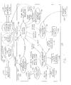
- FIG. 1 is a high level diagram of processes that may be carried out by the present invention.
- FIG. 2 is a high level flow diagram of an exemplary power management process method which may be performed by a control unit of the present invention.
- FIG. 3 is high level flow diagram of an exemplary mode determination process method which may be performed by a control unit of the present invention.
- FIG. 4 which includes FIGS. 4A through 4G, is a high level flow diagram of an exemplary user interface process method which may be performed by a control unit of the present invention.
- FIG. 5 is a high level flow diagram of an exemplary control process method which may be performed by a control unit of the present invention.
- FIG. 6 is a high level block diagram of components which may be used to effect at least some of the processes which may be performed by the present invention.
- FIG. 7 is perspective view of the outer surface of a control unit which may be used by the present invention.
- FIG. 8 is a partial transparent perspective view of the control unit of FIG. 7 .
- FIG. 9 is a rear view of the outer surface of the control unit.
- FIG. 10 illustrates a front panel which may be provided on the control unit.
- FIG. 11A is a partial transparent perspective view of a removable, disposable, pump cartridge which may be used by the present invention, in which a fluid level sensor is shown.
- FIG. 11B is a partial transparent perspective view of the removable, disposable, pump cartridge of FIG. 11A, in which a outlet pressure sensor is shown.
- FIG. 12A is a perspective view
- FIG. 12B is a partial transparent perspective view, of a sip tip oral fluid dispenser which may be used by the present invention.
- FIG. 13A is a perspective view
- FIG. 13B is a partial transparent perspective view, of a pump swab tip oral fluid dispenser which may be used by the present invention.
- FIG. 14A is a perspective view
- FIG. 14B is a partial transparent perspective view, of a swab tip oral fluid dispenser which may be used by the present invention.
- FIG. 15A is a perspective view
- FIG. 15B is a partial transparent perspective view, of a bite valve oral fluid dispenser which may be used by the present invention.
- FIG. 16A is a perspective view
- FIG. 16B is a partial transparent perspective view, of a drink straw oral fluid dispenser which may be used by the present invention.
- FIG. 17A is a perspective view
- FIG. 17B is a partial transparent perspective view, of a squeezer oral fluid dispenser which may be used by the present invention.
- FIG. 18A is front perspective view
- FIG. 18B is a rear perspective view, of a bedside cup attachment oral fluid dispenser which may be used by the present invention.
- FIG. 19 is a perspective view of a tube cup oral fluid dispenser which may be used by the present invention.
- FIG. 20 is a high level flow diagram of an exemplary input/output interface process method which may be performed by a control unit of the present invention.
- FIG. 21A is a plan view
- FIG. 21B is an end view
- FIG. 21C is a perspective view
- FIG. 21D is a side view of an alternative pump cartridge.
- FIG. 21E is a plan view
- FIG. 21F is an end view
- FIG. 21G is a perspective view
- FIG. 21H is a side view of the alternative cartridge including a fitting and a lid.
- FIG. 22 is a partial transparent perspective view of the alternative pump cartridge of FIGS. 21A through 21D.
- FIG. 23 is a perspective view of the fitting of FIGS. 21E through 21H.
- FIGS. 24A and 24B are cross-sectional side views of reservoir adapter caps which may be used with the pump cartridges of the present invention.
- the present invention concerns novel methods and apparatus for delivering fluids orally.
- the following description is presented to enable one skilled in the art to make and use the invention, and is provided in the context of particular applications and their requirements.
- Various modifications to the disclosed embodiments will be apparent to those skilled in the art, and the general principles set forth below may be applied to other embodiments and applications.
- the present invention is not intended to be limited to the embodiments shown.
- a first main function of the present invention is to deliver fluids.
- the present invention does so by providing a pump (such as a peristaltic pump for example), a pump cartridge, a fluid reservoir, and a variety of fluid dispensers, including oral fluid dispensers. Since a number of oral fluid dispensers are provided, the one best suited for the needs of a particular application can be selected.
- the operation of the pump may be controlled, at least in part, based on the type of fluid dispenser being used. Further, a selectable mode can be used to further control the operation of the pump.
- a second main function which may be performed by the present invention is to monitor the amount of fluids delivered over given periods of time. If too much or too little fluid is delivered (and presumably consumed), the present invention may provide a reminder (such as an audio and/or visual alarm for example). The thresholds for such alarm conditions may be set and modified by a user.
- Another function which may be performed by the present invention is to monitor the state of the fluid delivery system itself. Yet another function which may be performed by the present invention is monitoring trends in fluid delivery. Other functions which may be performed by the present invention will become apparent to those skilled in the art from the following description.
- FIG. 1 is a high level diagram of subassemblies which may be included in the present invention and processes which may be carried out by those subassemblies.
- electrical or control signal paths are indicated with solid lines
- fluid communication paths are indicated with stippled arrows
- a mechanical communication is indicated with a bold dashed line.
- the fluid delivery system 100 of FIG. 1 may include four (4) basic subassemblies—namely a pump cartridge 110 , a fluid reservoir 120 , and a fluid dispensing tube 130 , and a control unit 140 .
- a power supply 190 is depicted as being separate from the control unit 140 , it will be considered as a part of the control unit 140 in the following description.
- the pump cartridge 110 is arranged, fluidly, between the fluid reservoir 120 and the fluid dispensing tube 130 . Also, the pump cartridge 110 mechanically communicates with the pump 142 of the control unit 140 .
- control unit 140 is a major subassembly of the system 100 .
- the control unit subassembly includes a pump 142 , such as a peristaltic pump for example, a battery backup 144 to ensure uninterrupted power, an audio output device 146 , such as a speaker or piezo-electric element for example, a visual output device 148 , such as light emitting diodes and numeric displays for example, and an input device 150 , such as a keypad and/or clock setting buttons for example.
- the control unit 140 may also include a memory for storing parameter values and state information.
- a number of processes such as a control process 160 , a mode determination process 162 , a user interface process 164 , a power management process 166 , and a clock/timer process 168 for example, may be carried out by the control unit 140 , and an input/output interface process 169 .
- a control process 160 may be carried out by the control unit 140 , and an input/output interface process 169 .
- a mode determination process 162 may be carried out by the control unit 140 , and an input/output interface process 169 .
- the control process 160 may provide “pump speed” and “pump direction” control signals to the pump 142 and may accept “pump RPM”, “pump inlet pressure” and “pump outlet pressure” values from the pump 142 .
- the control process 160 may also accept “outlet pressure” and “fluid level” values from the pump cartridge 110 , and a “mode” value form the mode determination process 162 .
- the control process 160 may accept inputs from the user interface process 164 and may provide display values and alarm signals to the user interface process 164 .
- the control process 160 may accept a “power status” signal from the power management process 166 and provide a “battery backup switchover” command to the power management process 166 .
- An exemplary control process method 160 ′ is described in ⁇ 4.2.3.4 below with reference to FIG. 5 .
- the mode determination process 162 may accept an “attachment type” value from the pump cartridge 110 and may accept “per/drink dosage”, “mode”, “prime?”, “minimum/hour limit”, and “maximum/hour limit” values from the user interface process 164 . As introduced above, the mode determination process 162 may provide a “mode” value to the control process 160 .
- An exemplary mode determination process method 162 ′ is described in ⁇ 4.2.3.2 below with reference to FIG. 3 .
- the user interface process 164 may accept inputs from input devices 150 and display values and alarms from the control process 160 , and may provide keypad input indications to the control process, and outputs to the visual output device(s) 148 and the audio output device(s) 146 .
- An exemplary user interface process method 164 ′ is described in ⁇ 4.2.3.3 with reference to FIG. 4 .
- the clock timer process 168 may be used by the other processes and basically maintains a time and can perform timing functions.
- This “system clock” may be maintained by a separate, replaceable, battery 152 , such as a lithium battery for example.
- the input/output interface process 169 may implement communications protocol stacks for (i) accepting system parameters, (ii) accepting system software updates, (iii) accepting remote testing triggers, (iv) providing fluid delivery trend reports (such as, for example, historic data detailing flow rates, volumes, etc.), and/or (v) providing system test results.
- This process 169 may use a serial interface for example, such as an RS-232 interface for example.
- An exemplary input/output interface process method 169 ′ is described in ⁇ 4.2.3.5. below with reference to FIG. 20 .
- a power management process 166 may monitor states of a power supply 190 and a battery backup 144 . As discussed above, it may provide a power status message to the control process 160 and may receive a battery backup switchover command from the control process 160 . In response to such a command, it may control the power supply 190 and the battery backup 144 . Alternatively, the power management process 166 may control the switchover itself and merely provide status messages to the control process 160 .
- An exemplary power management process method 166 ′ is described in ⁇ 4.2.3.1 below with reference to FIG. 2 .
- the pump cartridge 110 may perform an attachment type detection process 112 for detecting the type of oral fluid dispenser 130 being used (or alternatively, may indicate an operating mode, such as negative pressure, positive pressure, or free flow for example), a fluid level sensing process 114 for monitoring the fluid level of the fluid reservoir 120 , and an outlet pressure sensing process 116 for monitoring the fluid pressure at its outlet.
- an attachment type detection process 112 for detecting the type of oral fluid dispenser 130 being used (or alternatively, may indicate an operating mode, such as negative pressure, positive pressure, or free flow for example)
- a fluid level sensing process 114 for monitoring the fluid level of the fluid reservoir 120
- an outlet pressure sensing process 116 for monitoring the fluid pressure at its outlet.
- a control unit subassembly 140 is described in ⁇ 4.2.2.1
- pump cartridge subassemblies 110 are described in ⁇ 4.2.2.2
- oral fluid dispenser subassemblies (or fluid dispensing tubes) 130 are described in ⁇ 4.2.2.3.
- the fluid reservoir subassembly 20 may include various types of containers such as plastic or glass bottles. That is, the present invention is designed to work with various types of known fluid containers.
- the fluid reservoir 120 used may preferably hold from 12 to 16 ounces of fluid and should be sized so that the control unit 140 is not easily tipped (that is, maintains a low center of gravity) when it is fitted with the reservoir 120 .
- the fluid reservoir 120 may be provided with a removable bottom such that, when it is fitted (upside-down) into the control unit 140 , the fluid reservoir 120 can be filled with more fluid or ice, for example, by removing the removable bottom.
- the fluid reservoir 120 may be provided with an adapter cap, described in ⁇ 4.2.2.2 below, which is accepted by a fitting in the pump cartridge 110 .
- the reservoir may be provided with a tube extending into its interior such that it can be arranged, in various orientations, apart from the control unit 140 .
- FIG. 7 is a perspective view of an exemplary embodiment of the control unit 140 ′.
- the control unit 140 ′ is designed with a low center of gravity, preferably below split line 710 .
- the external dimensions of the exemplary embodiment of the control unit 140 ′ may be about five (5) inches wide by about nine (9) inches long and about five (5) inches high.
- the shell of the exemplary embodiment of the control unit 140 ′ may be constructed of plastic injected molded pieces, and is preferably non-toxic, resistant to discoloration or chemical (for example, alcohol or disinfectant) decomposition.
- An area 720 for receiving the fluid reservoir 120 is also provided. As shown in the partially transparent perspective view of FIG.
- a pump cartridge 110 ′ is removably accommodated in the control unit 140 ′ and includes an fitting 1130 for receiving the fluid reservoir 120 .
- the reservoir may be provided with a valve cap and the fitting 1130 may include an actuator for opening the valve cap when the reservoir is properly seated. In this way, the reservoir 120 can be seated onto (and removed from) the fitting 1130 without fluid spills.
- a control panel 730 to be described in more detail below, is provided.
- FIG. 9 is a rear view of the exemplary embodiment of the control unit 140 ′.
- the rear of the pump cartridge 110 ′ is exposed at the rear of the control unit 140 ′ and includes a tubing connection 910 , such as a nipple for example.
- the control unit 140 ′ includes a power switch 920 , a power input port 925 , a input/output interface port 930 , such as a serial (e.g., RS232) port for example, and switches 940 for setting the hours and minutes of a system clock.
- the pump cartridge 110 ′ overhangs the electrical components and switches of the control unit 140 ′ such that any fluid spills may be diverted from these electrical components and switches.
- the control unit 140 ′ may have an integral overhang.
- FIG. 10 illustrates an exemplary keypad and display 730 which may be provided on the control unit 140 ′.
- a keypad portion defined by keys 1012 , 1020 , 1032 , 1042 , 1050 , and 1060 , may be part of a fluid resistant, membrane switch.
- Each of the keys may include stainless steel domes for providing tactile feedback when a key is pressed.
- a beeper may provide audible feedback when a key is pressed.
- An alarm section 1010 further includes status LEDs 1014 through 1018
- a limit section 1030 further includes status LEDs 1034 and 1036
- a drink mode section 1040 further includes status LEDs 1044 and 1046 .
- a power LED 1070 may also be provided.
- a four (4) digit, seven (7) segment, alpha numeric display 1080 may be provided.
- Display type indicators 1082 , 1084 , 1086 , and 1088 may be backlit “dead front” text messages.
- the power supply 190 may serve to convert unregulated input power from a wall mount power supply into regulated voltage levels (such as +12 volt @ 1 amp for example) used by the various electrical circuits and the pump of the system 100 .
- a wall mounted power supply 190 may provide electrical isolation (such as 4000 volts for example) from the AC power input. (Pressure transducers in the pump cartridge may provide additional electrical isolation, such as 1500 volts of isolation for example.)
- a battery backup 144 may be provided with a trickle change as needed.
- the battery backup 144 may even be charged when the power switch 920 has been turned off.
- the battery pack 144 may provide four (4) hours of backup power in the event of AC power failure.
- the battery pack 144 may be user replaceable and may be accessed via the underside of the control unit 140 ′.
- the control unit 140 ′ may also house a pump 142 (not shown), such as a peristaltic pump with a gear reduction assembly and a multi-roller pump head for example.
- a pump 142 such as a peristaltic pump with a gear reduction assembly and a multi-roller pump head for example.
- FIGS. 11A and 11B provide two perspective, partially transparent views of an exemplary embodiment of the pump cartridge 110 ′.
- a reservoir 120 ′ is held by fitting 1130 . Fluid from the reservoir 120 ′ will flow through pump tubing 1125 which is provided against a curved wall 1120 .
- the roller head of a peristaltic pump (not shown) will extend through the opening 1110 defined in the pump cartridge 110 ′ such that the rollers of its head engage the pump tubing 1125 .
- the rear of the pump cartridge 110 ′ may include a tubing connection 910 , such as a nipple for example.
- a fluid level sensor 1140 may be provided.
- This sensor 1140 may inform the control unit 140 when there is only one (1) to two (2) inches of fluid remaining in the reservoir for example.
- This sensor 1140 may be used to perform the fluid level sensing process 114 depicted in FIG. 1 .
- an outlet pressure sensor 1150 may be provided.
- This sensor 1150 may be used to perform the outlet pressure sensing process 116 depicted in FIG. 1 .
- These sensors 1140 and 1150 may be transducers for example.
- the pump cartridge 110 ′ may include a quick disconnect electrical (or optical or mechanical) connection, such as conductive pad contacts for example, for passing signals from the sensors 1140 and 1150 to the control unit 140 ′.
- the pump cartridge 110 ′ may detect physical, optical, or electrical or conductive contacts on a connected fluid dispensing tube 130 to at least determine whether the fluid dispensing tube is intended to operate in a negative or positive pump pressure mode, and perhaps to identify the exact type of fluid dispensing tube 130 attached.
- FIGS. 21A through 21H and 22 An alternative pump cartridge 110 ′′ is depicted in FIGS. 21A through 21H and 22 . More specifically, FIG. 21A is a plan view, FIG. 21B is an end view, FIG. 21C is a perspective view, FIG. 21D is a side view, and FIG. 22 is a partial transparent perspective view of the alternative pump cartridge 110 ′′.
- the alternative pump cartridge 110 ′′ basically includes a shell, defined by side walls 2192 and 2194 , front wall 2196 , rear wall 2198 , and floor 2190 , and tubing 2125 . Within the shell, a cartridge reservoir is defined by floor 2190 , side wall 2192 , front wall 2196 , rear wall 2198 , nipple wall 2193 , and internal wall 2199 . The cartridge reservoir is covered (not shown).
- FIGS. 21E through 21H, 23 , 24 A, and 24 B when an adapter cap 2400 / 2400 ′ of a reservoir is placed onto a fitting 2130 , a projection 2170 of the fitting 2130 opens a valve normally biased closed and fluid from the reservoir flows into the cartridge reservoir.
- the pump cartridge 110 ′′ may include a fitting 2130 (or 1130 ) for accepting a reservoir having an adapter cap 2400 / 2400 ′ (described below).
- the fitting 2130 includes a cup portion defined by a cylindrical wall 2172 and a floor 2173 .
- An opening 2171 is defined in a portion of the floor 2173 arranged over the projection 2170 .
- a skirt 2174 having flow openings 2175 .
- FIGS. 24A and 24B are cross-sectional side views of a cup adapter 2400 / 2400 ′.
- the end of a reservoir such as a threaded bottle for example, is fit into cylindrical section 2405 .
- a plunger seat 2430 passes through the opening 2171 and is engaged by the projection 2170 .
- the value seat 2410 which is normally biased closed by spring 2120 is opened and fluid flows from the reservoir, out the valve opening, through openings in a skirt 2440 of the cup adapter 2400 / 2400 ′, through opening 2171 and through flow openings 2175 in the skirt 2174 of the fitting 2130 , into the cartridge reservoir.
- the cap adapter 2400 ′ may include guides 2450 , such a posts for example, for guiding the movement of the plunger seat 2430 .
- Fluid then can enter tubing 2125 via an opening in the nipple wall 2193 and nipple 2180 .
- the tubing 2125 will have been snuggly fit, for example by stretching, around rollers of a peristaltic pump (not shown).
- a peristaltic pump not shown.
- fluid will be drawn from the cartridge reservoir and will exit at a port at the rear wall 2198 of the cartridge 110 ′′. (Recall, e.g., the outlet 910 of FIG. 9.)
- the assembly 2140 includes a light transmission part 2142 (such as a multifaceted prism for example), a light blocking part 2146 (such as a floatable ball for example), a light receiving part 2144 (such as a prism for example), and a containment wall (only a part of which is shown) 2148 for containing lateral movement of the light blocking part 2146 .
- a light source such as an LED for example, provided in the control unit 140 emits light into the prism 2142 and a light sensor (not shown), such as a photo conductive element for example, provided in the control unit 140 collects light from the prism 2144 .
- the first prism 2142 is arranged to direct light towards the second prism 2144 . If the cartridge reservoir is full, the light blocking element 2146 contained by the walls 2148 and the prisms 2142 , 2144 , will float, thereby blocking light emitted from the first prism 2142 from entering the second prism 2144 . However, when the cartridge reservoir is empty (or almost empty), the light blocking element 2146 will drop, thereby enabling light emitted from the first prism 2142 to be detected by the second prism 2144 . Thus, when the light sensor associated with the second prism 2144 fails to detect light, a low reservoir level is inferred. Naturally, this level sensing arrangement 2140 might not be suitable for use with relatively opaque fluids.
- the prism 2142 can be provided with additional facets for directing light towards prisms 2160 A and 2160 B.
- the control unit 140 may include further light sensors, each associated with one of the prisms 2160 a and 2160 b.
- Different cartridges may be provided for dispensers having different flow characteristics, such as negative flow, positive flow, and free flow for example. Such different cartridges may be provided with either one, or both of the additional prisms 2160 A and 2160 B.
- a positive flow cartridge may include both prisms 2160 A and 2160 B such that the additional light sensors of the control unit 140 detect light (indicating a positive flow)
- a negative flow cartridge may include only prism 2160 A such that only one of the additional light sensors of the control unit 140 detects light (indicating a negative flow)
- a free flow cartridge may include only prism 2160 B such that only the other one of the additional light sensors of the control unit 140 detects light (indicating a free flow).
- a pressure transducer 2150 may measure the pressure in the tube exiting the cartridge 110 ′′.
- Either of the pump cartridges 110 ′ or 110 ′′ may include an expansion chamber (not shown), such as a stretchable bladder having shape memory for example, so that pressure can build in the cartridge and drops in pressure may be sensed by the sensor by outlet pressure sensor 1150 or 2150 .
- an expansion chamber such as a stretchable bladder having shape memory for example, so that pressure can build in the cartridge and drops in pressure may be sensed by the sensor by outlet pressure sensor 1150 or 2150 .
- an expansion chamber need not be provided.
- Either of the pump cartridges 110 ′ or 110 ′′ may also include a valve built into its outlet so that if a fluid dispensing tube 130 is disconnected, no fluid will leak from the outlet 910 of the pump cartridge 110 ′ or 110 ′′.
- fluid filtration means may be provided in the pump cartridge 110 ′ or 110 ′′ (and/or the reservoir valve cap, and/or the fluid dispensing tube 130 ).
- FIGS. 12A through 19 depict various types of oral fluid dispensers.
- these dispensers may include, or may be connected to, a short section (such as four (4) feet, for example) of tubing having a distal end connected with the tubing connection 910 of the pump cartridge 110 ′.
- a short section such as four (4) feet, for example
- FIG. 12A is a perspective view
- FIG. 12B is a partial transparent perspective view, of a sip tip oral fluid dispenser 1200 which may be used by the present invention.
- the sip tip oral fluid dispenser 1200 includes a proximal end 1210 , a distal end 1220 , and may include a check valve 1230 .
- This dispenser 1200 functions as does a simple straw; fluid is obtained by a sucking action at the proximal end 1210 .
- the check valve 1230 reduces the possibility of fluid leakage and/or back flow.
- FIG. 13A is a perspective view
- FIG. 13B is a partial transparent perspective view, of a pump swab tip oral fluid dispenser 1300 which may be used by the present invention.
- the pump swab tip oral fluid dispenser 1300 includes a swab tip 1320 at its proximal end.
- the material forming the swab tip 1320 should be soft and absorbent, or sponge like, so that it can retain water. Fine control of water quantity is provided by the pump actuator 1330 which is an exposed area of a soft inner bladder.
- a first check valve 1350 may be provided at the proximal end of the dispenser 1300
- a second check valve 1340 may be provided at the distal end 1310 of the dispenser 1300 .
- the pump swab tip oral fluid dispenser 1300 may be used to wet the lips of a user with small amounts of water.
- This fluid dispenser 1300 may be provided with a shorter distance between the pump actuator 1330 and the swab tip 1320 for wetting a user's lips, or a longer distance between the pump actuator 1330 and the swab tip 1320 for moistening the inside of a user's mouth.
- FIG. 14A is a perspective view
- FIG. 14B is a partial transparent perspective view, of a swab tip oral fluid dispenser 1400 which may be used by the present invention.
- This fluid dispenser 1400 is similar to the pump swab tip oral fluid dispenser 1300 in that is has a soft tip 1420 at its proximal end.
- a valve 1440 and valve actuator 1430 are provided rather than a soft bladder and pump 1330 .
- water begins to flow to the surface of the soft swab tip 1420 , until the valve actuator 1430 is released.
- the swab tip oral fluid dispenser 1400 may be provided with a shorter distance between the pump actuator 1430 and the swab tip 1420 for wetting a user's lips, or a longer distance between the pump actuator 1430 and the swab tip 1420 for moistening the inside of a user's mouth.
- FIG. 15A is a perspective view
- FIG. 15B is a partial transparent perspective view, of a bite valve oral fluid dispenser 1500 which may be used by the present invention.
- a bite valve actuator 1520 opens valve 1530 when a user bites downs on it. Fluids enter at the distal end 1510 of the dispenser 1500 .
- the bite valve oral fluid dispenser 1500 may be used to provide a continuous flow of fluid when a user bites down on the actuator 1520 . When the user stops biting, the fluid flow ceases.
- FIG. 16A is a perspective view
- FIG. 16B is a partial transparent perspective view, of a drink straw oral fluid dispenser 1600 which may be used by the present invention.
- a valve actuation button 1640 is provided between the proximal 1620 and distal 1610 ends. When the value actuation button 1640 is pressed, the valve 1640 opens.
- the operation of this dispenser 1600 is similar to that of the bite valve oral fluid dispenser 1500 , except that a user presses a button valve actuator 1630 , rather than biting a bite value actuator 1520 .
- FIG. 17A is a perspective view
- FIG. 17B is a partial transparent perspective view, of a squeezer oral fluid dispenser 1700 which may be used by the present invention.
- This dispenser 1700 includes a squeezable bladder 1730 , which may be held in a user's hand, for allowing a user to pump water through check valve 1750 to the proximal end 1720 .
- a second check valve 1740 is provided at the distal end 1710 .
- the squeezable bladder 1730 may be about three (3) to six (6) inches long, for example, and may hold about 15 to 30 ml of fluid for example.
- FIG. 18A is front perspective view
- FIG. 18B is a rear perspective view, of a bedside cup attachment oral fluid dispenser 1800 which may be used by the present invention.
- This dispenser 1800 permits a user to fill a small cap, such as a standard 2.5 ounce “dixie” type cup 1870 for example, at their bed.
- the dispenser 1800 is “C-shaped” and defines a hood 1820 and a cup holder 1880 .
- a button 1840 is provided on the dispenser 1800 , and in this exemplary embodiment, on the hood 1820 , and allows the user to refill the cup 1870 with fluid.
- a fluid delivery tube 1860 is, in this exemplary embodiment, attached to the rear of the dispenser 1800 .
- a clamp 1830 permits the dispenser to be removably fixed to a bed rail 1810 .
- the cup holder 1880 may include a drain for draining any spilled fluid or fluid inadvertently dispensed into a full cup 1870 or inadvertently dispensed when a cup 1870 is not situated in the holder 1880 .
- the bedside cup attachment oral fluid dispenser 1800 may be placed on a bedside table and need not include the clamp 1830 .
- the supply tube 1860 would preferably extend roughly parallel to the bottom surface of the dispenser 1800 and the dispenser 1800 would preferably be weighted to have a low center of gravity.
- FIG. 19 is a perspective view of a tube cup oral fluid dispenser 1900 which may be used by the present invention.
- This dispenser 1900 offers similar features as the bedside cup attachment oral fluid dispenser 1800 , but further permits a user to refill the cup 1960 without returning it to its holder 1920 . That is, the tube 1930 can be removed from its holster 1925 .
- the holster 1925 includes a water refilling button 1940 which, when pressed, presses a valve actuator (not shown) on the tube 1930 .
- a hanger member 1910 attached to the cup holder 1920 , may be hung form a bed rail 1950 .
- the cup holder 1920 could have an smaller inner diameter so that the top of the cup 1960 could be more easily grasped by the user.
- the tube holster 1925 may be extended upward so that the curved section of the tube 1930 would be at least a cup's length above the top of the cup holder 1920 . In this way, a user could more easily remove the cup 1960 without inadvertently hitting the curved end of the tube 1930 . As can be appreciated by one skilled in the art, this embodiment could be modified to sit on a bedside table.
- a system 600 may include a bus or network 610 coupled with a processor(s) 620 , a storage device(s) 630 and an input/output interface(s) 640 .
- the storage device(s) 630 may include flash memory.
- stored instructions may be updated in the field.
- the input/output interface(s) 640 may include an RS-232 serial port. In this way, the stored instructions may be updated, or new instructions may be directly provided, from an external source, and information, such as trend information for example, may be uploaded to an external system for analysis.
- the processor(s) 620 may be a low power general purpose microprocessor, or an application specific integrated circuit (or “ASIC”) for example.
- exemplary methods which may be used to carry out the processes are now described below.
- First, an exemplary power management process method is described in ⁇ 4.2.3.1.
- Second, an exemplary mode determination process method is described in ⁇ 4.2.3.2.
- Third, an exemplary user interface process method is described in ⁇ 4.2.3.3.
- Fourth, an exemplary control process method is described in ⁇ 4.2.3.4.
- Finally, an exemplary input/output interface process is described in ⁇ 4.2.3.5.
- the methods described and the operations that they perform are exemplary; in some cases, operations from different methods can be combined under a single method, operations from a single method can be separated and performed by separate methods, or operations performed one method may be performed by a different method than the one illustrated. Similarly, in some cases, a process can be carried out in a subassembly other than the one illustrated.
- FIG. 2 is a flow diagram of an exemplary power management process method 166 ′.
- the line that is, the power coming in from the power supply 190
- the power management process may either directly, or via the control process 160 , inform the user interface process 164 that battery power is being used.
- the user interface process 164 may enter a low power operating mode in which the visual outputs 148 are blanked after a period of keypad inactivity.
- FIG. 3 is a flow diagram of an exemplary power management process method 162 ′.
- the mode determination process accepts an “attachment type” value from the pump cartridge 110 .
- “per drink dosage mode”, “prime?”, “min/hr limit”, and “max/hr limit” values are accepted from the user interface process 164 .
- a mode is determined based on at least some of the accepted values listed above.
- the “mode” value determined is provided to the control process 160 . (See, e.g., FIG. 1.)
- decision step 401 it is determined whether a reservoir low alarm has been received (either directly from the fluid level sensing process 114 , or via the control process 160 ). If so, the “reservoir” LED 1018 is lit as shown in step 402 . An audible alarm may also sound.
- decision step 403 it is determined whether the reservoir has been replaced or refilled. If so, the alarm is cleared (and the “reservoir” LED 1018 is extinguished) as shown in step 404 and processing continues to decision step 405 . Otherwise, processing continues directly to decision step 405 .
- decision step 401 if a reservoir low alarm is not received, processing continues directly to decision step 405 .
- decision step 405 it is determined whether the battery backup 144 , rather than power supply 190 , is providing power (either directly from the power management process 166 , or via control process 160 ). If so, the “battery” LED 1016 is lit as shown in step 406 . An audible alarm may also sound.
- decision step 407 it is determined whether the AC power, from power supply 190 , has been restored. If so, the alarm is cleared (and the “battery” LED 1016 is extinguished) as shown in step 408 and processing continues, via node A 409 , to decision step 410 . Otherwise, processing continues, via node A 409 , to decision step 410 .
- the battery backup 144 is not being used, but rather, the power supply 190 is being used, processing continues, via node A 409 , to decision step 410 .
- decision step 410 it is determined whether the min/hour dosage or max/hour dosage thresholds have been met (from control process 160 ). If so, the “limits” LED 1014 is lit as shown in step 411 . An audible alarm may also sound.
- decision step 412 it is determined whether the alarms key 1012 has been pressed (to clear this alarm condition). If so, the alarm is cleared (and the “limits” LED 1014 is extinguished) as shown in step 413 and processing continues to decision step 414 . Otherwise, processing continues directly to decision step 414 . Returning to decision step 410 , if the min/hour or max/hour dosage thresholds are not met, processing continues directly to decision step 414 .
- decision step 414 it is determined whether a hardware or software failure has been detected (from control process 160 ). If so, the “system” LED 1015 is lit as shown in step 414 . An audible alarm may also sound.
- decision step 416 it is determined whether the system or hardware failure is due to a spurious failure. If so, the alarm is cleared (and the “system” LED 1016 is extinguished) as shown in step 417 and processing continues, via node B 418 , to decision step 419 . Otherwise, processing continues, via node B 418 , to decision step 419 .
- decision step 414 if no hardware or software error is detected, processing continues, via node B 418 , to decision step 419 .
- decision step 419 it is determined whether the output button 1020 is being pressed. If not, processing continues, via node C 426 , to decision step 427 . If, on the other hand, it is determined that the output button 1020 is being pressed, the total amount of fluids consumed (in a most recent time period) are displayed on numeric display 1080 and the mL indicator 1083 is backlit. Next, as shown in decision step 421 , it is determined whether the output button 1020 is pressed again within a short predetermined time, such as three (3) seconds for example. If so, the elapsed time corresponding to the volume consumed is displayed on numeric display 1080 and the “elapsed” indicator 1084 is backlit.
- a short predetermined time such as three (3) seconds for example.
- decision step 423 it is determined whether the output button 1020 is pressed again within a short predetermined time, such as three (3) seconds for example. If so, processing continues back to step 420 . If not, or, returning to step 421 , if the output button was not pressed again within the short predetermined time, such as three (3) seconds for example, processing continues to decision step 424 . As shown in decision step 424 , if the output button 1020 is not pressed again within a longer predetermined time, such as one (1) minute for example, processing continues, via node C 426 , to decision step 427 .
- a short predetermined time such as three (3) seconds for example.
- the output button 1020 is pressed again within the longer predetermined time, such as one (1) minute for example, the time and volume data is cleared (and the associated LED is extinguished) as shown in step 425 , and processing continues, via node C 426 , to decision step 427 .
- step 427 it is determined whether or not the “drink mode” button 1042 is pressed. If so, processing branches to decision step 428 where it is determined whether a current mode is a “control” mode or a “normal” mode. Basically, as will be apparent from the following description, pressing the drink mode serves to toggle the mode between “control” and “normal”. If the current mode was “control”, the “normal” mode is entered as shown in step 429 . In this mode, the display 1080 indicates a predetermined fluid dosage, such as 30 ml for example, as shown in step 430 . Finally, the “normal” LED 1044 is lit and the “control” LED 1046 is extinguished. Processing then continues to decision step 450 .
- a current mode is a “control” mode or a “normal” mode. Basically, as will be apparent from the following description, pressing the drink mode serves to toggle the mode between “control” and “normal”. If the current mode was “control”, the “normal” mode is entered as shown in step 429 . In this mode, the
- step 428 if the current mode was determined to be the “normal” mode, the “control” mode is entered as shown in step 432 .
- step 433 the “normal” LED 1044 is extinguished and the “control” LED 1046 is lit.
- step 434 the current dosage value is flashed on display 1080 . If, as shown in decision steps 435 and 436 , and step 437 , an up arrow key 1050 is hit within a predetermined time period, such as one (1) minute for example, the dosage is incremented (by a predetermined amount such as 1 ml or 10 ml for example), and processing returns to step 434 .
- step 435 the longer the up arrow key 1050 is pressed, the faster the dosage value will be incremented. If, as shown in decision steps 435 , 436 and 438 , and step 439 , a down arrow key 1050 is hit within a predetermined time period, such as one (1) minute for example, the dosage is decremented, and processing returns to step 434 . Alternatively, the longer the down arrow key 1050 is pressed, the faster the dosage value will be decremented. Returning to step 435 , if neither arrow key is pressed within the predetermine time period, such as one (1) minute for example, processing continues to decision step 450 . Returning to step 427 , if the “drink mode” button is not being pressed, then processing continues directly to decision step 450 .
- decision step 450 it is determined whether the “prime” button 1060 is being depressed. If so, the pump 142 is run until the “prime” button 1060 is released, at which time processing continues, via node D 452 , to decision step 453 . Returning to decision step 450 , if the “prime” button 1060 is not being pressed, processing continues, via node D 452 , to decision step 453 .
- step 453 it is determined whether or not the “limit/hr” button 1032 is being pressed. If so, processing proceeds to decision step 454 where it is determined whether the current limit is min or max. If the current limit was determined to be the “min” mode, the “max” mode is entered as shown in step 455 . Next, as shown in step 456 , the “min” LED 1036 is extinguished and the “max” LED 1034 is lit. Next, as shown in step 457 , the current dosage value is flashed on display 1080 .
- an up arrow key 1050 is hit within a predetermined time period, such as one (1) minute for example, the dosage is incremented (by a predetermined amount such as 1 ml or 10 ml for example), and processing returns to step 457 .
- a predetermined time period such as one (1) minute for example
- the dosage is decremented, and processing returns to step 457 .
- step 458 if neither arrow key 1050 is pressed within the predetermine time period, such as one (1) minute for example, processing continues, via node E 471 , to decision step 472 .
- step 454 if the current limit value is “max” mode, the “min” mode is entered as shown in step 463 .
- step 464 the “max” LED 1034 is extinguished and the “min” LED 1036 is lit.
- step 465 the current dosage value is flashed on display 1080 . If, as shown in decision steps 466 and 467 , and step 468 , an up arrow key 1050 is hit within a predetermined time period, such as one (1) minute for example, the dosage is incremented (by a predetermined amount such as 1 ml or 10 ml for example), and processing returns to step 465 .
- step 466 the longer the up arrow key 1050 is pressed, the faster the dosage value will be incremented. If, as shown in decision steps 466 , 467 and 469 , and step 470 , a down arrow key 1050 is hit within a predetermined time period, such as one (1) minute for example, the dosage is decremented, and processing returns to step 465 . Alternatively, the longer the down arrow key 1050 is pressed, the faster the dosage value will be decremented. Returning to step 466 , if neither arrow key 1050 is pressed within the predetermine time period, such as one (1) minute for example, processing continues, via node E 471 , to decision step 472 .
- a predetermined time period such as one (1) minute for example
- step 453 if the “limit per hour” button 1032 was not pressed, then processing continues, via node E 471 , to decision step 472 .
- step 472 it is determined whether or not a clock set hour button 940 is being pressed. If so, as shown in step 473 , the time is displayed on display 1080 and the “time” panel 1088 is backlit. In decision step 474 , it is determined whether the down arrow key 1050 is pressed and the clock set hour key 940 is still depressed. If so, as shown in step 475 , the hour is decremented. If not, processing continues to decision step 476 . In decision step 476 , it is determined whether the up arrow key 1050 is pressed and the clock set hour key 940 is still depressed. If so, as shown in step 477 , the hour is incremented. If not, processing continues to decision step 478 . Returning to decision step 472 , if the clock set hour button is not being pressed, processing continues directly to decision step 478 .
- step 478 it is determined whether or not a clock set minute button 940 is being pressed. If so, as shown in step 479 , the time is displayed on display 1080 .
- decision step 480 it is determined whether the down arrow key 1050 is pressed and the clock set minute key 940 is still depressed. If so, as shown in step 481 , the minute is decremented. If not, processing continues to decision step 482 .
- decision step 482 it is determined whether the up arrow key 1050 is pressed and the clock set minute key 940 is still depressed. If so, as shown in step 483 , the hour is incremented. If not, processing continues, via node F 484 , to decision step 485 . Returning to decision step 478 , if the clock set minute button is not being pressed, processing continues, via node F 484 , to decision step 485 .
- step 485 it is determined whether it is time to replace (or clean) any fluidic component or components (such as a dispenser 130 or the pump cartridge 110 . If so, as shown in step 486 , a cleaning LED 1017 is lit and an audible alarm may be provided. Next, as shown in step 487 , it is determined whether or not the alarms button 1012 was pressed or the relevant fluidics component was replaced. If so, the alarm is cleared (and the cleaning LED 1017 is extinguished), as shown in step 488 , and processing continues to return node 489 . If not, processing continues directly to return node 489 . Returning to decision step 485 , if it is determined that it is not yet time to replace (or clean) a fluidic component or components, processing continues directly to return node 489 .
- FIG. 5 is a flow diagram of an exemplary control process method 160 ′.
- the process accepts an “outlet pressure” and “fluid level” values from the pump cartridge 110 , as well as “pump RPM”, “inlet pressure” and “outlet pressure” values from the pump 142 , and the “mode” value from the mode determination process 162 . (See, e.g., FIG. 1.)
- “pump speed” and “pump direction” values are determined based on some or all of the above mentioned accepted values.
- the “pump speed” and “pump direction” values are provided as commands to the pump 142 .
- a “fluid level” value accepted is below a predetermined threshold. In an alternative method, this determination may be made by the fluid level sensing process 114 itself. In any event, if the fluid level is below the predetermined threshold, as shown in step 560 , an appropriate alarm signal is provided to the user interface process 164 . Further, as shown in step 570 , a “line power status” value is accepted from the power management process 166 . If the status of the line power is not acceptable, the control process may instruct the power management process 166 to switch over to battery power as shown in step 590 . As discussed above, in an alternative method, the power management process 166 may make a switch over determination itself and merely inform the control process 160 when it has done so.
- the control process 160 may also perform a variety of self tests, for example during power up and periodically or continuously during operation. Such self tests may include battery voltage monitoring, system memory tests, data acquisition tests, pressure sensor tests, LED and display tests, processor integrity tests, and stuck keyboard switch tests, for example. Naturally, these tests may be distributed to other processes which may provide their results back to the control process 160 . If a failure is detected, the user interface process 164 may be informed. (Recall decision step 414 of the exemplary user interface process method 164 ′.)
- FIG. 20 is a flow diagram of an exemplary input/output interface process method 169 ′.
- this trigger may be passed to the control process 160 for performing or initiating some sort of system test.
- decision step 2020 and step 2025 if test results are provided to the input/output interface process 169 , it may upload those test results to a remote monitor.
- the remote monitor is a device other than the fluid delivery system and therefore may be a local computer or a remote computer for example.
- decision step 2030 and step 2035 if a trend report is provided from the system, such a report may be uploaded to a remote monitor.
- decision steps 2040 and 2042 if new software, or a notification of the availability of new software, is received from a remote source, the user may be notified, for example via the control process 160 and user interface process 164 .
- decision step 2044 and step 2046 if the user accepts the new software, the update is downloaded and may be provided to the control process 160 .
- new software can be downloaded and implemented automatically, without the need for user approval.
- the method 169 ′ is exited via return node 2050 .
- a pump cartridge 110 ′ is placed in the control unit 140 ′ as shown in FIG. 8.
- a fluid reservoir 130 ′ (which may have an adapter cap 2400 / 2400 ′) is positioned through the opening 720 and is engaged with the fitting 1130 (or 2130 ).
- the power switch 920 is turned on.
- the distal end of one of the oral fluid dispensers, or the distal end of a tube section connected with one of the oral fluid dispensers, is attached to connector 910 .
- the priming button 1060 is pushed.
- the pump motor turns, its rollers engaging the pump tubing 1125 (or 2125 ) of the pump cartridge 110 ′ (or 110 ′′), thereby pushing air out of the system and drawing fluid from the reservoir 120 ′.
- the user may draw fluid from the system, either by sucking on the end 1210 of the sip tip oral fluid dispenser 1200 , pressing on the bladder 1330 of the pump swab tip oral fluid dispenser 1300 , pressing the valve actuator 1430 of the swab tip oral fluid dispenser 1400 , biting the bite valve actuator 1520 of the bite valve oral fluid dispenser 1500 , pressing the button valve actuator 1630 of the drink straw oral fluid dispenser 1600 , squeezing the squeezable bladder 1730 of the squeezer oral fluid dispenser 1700 , pressing the button 1840 of the bedside cup attachment oral fluid dispenser 1800 , or by pressing the button 1940 of the tube cup oral fluid dispenser 1900 .
- the outlet pressure sensor 1150 (or 2150 ) performs an outlet pressure sensing process 116 to provide an outlet pressure to a control process 160 .
- the control process 160 Based on the outlet pressure, as well as a mode value, the control process 160 provides pump speed and/or pump direction commands to the pump 142 .
- the system of the patent invention may use two ( 2 ) basic parameters—namely dispenser (or tip) type, and a selected “drink mode”—for determining the its mode of operation.
- dispenser or tip
- a selected “drink mode” for determining the its mode of operation.
- the various dispenser (or tip) types disclosed operate with a positive fluid pressure or a slight negative fluid pressure.
- the present invention provides a system for delivering fluids which includes a pump (such as a peristaltic pump for example), a pump cartridge, a fluid reservoir, and a variety of fluid dispensers, including oral fluid dispensers.
- a pump such as a peristaltic pump for example
- a pump cartridge such as a peristaltic pump for example
- a fluid reservoir such as a peristaltic reservoir
- fluid dispensers including oral fluid dispensers.
- oral fluid dispensers including oral fluid dispensers.
- the pump cartridge and/or the fluid dispensers are disposable.
- the operation of the pump may be controlled based, at least in part, on the type of fluid dispenser being used. Further, a selectable mode can be used to further control the operation of the pump.
- the present invention may provide a reminder (such as an audio and/or visual alarm for example) if too much or too little fluid is delivered (and presumably consumed).
- a reminder such as an audio and/or visual alarm for example
- the thresholds for such alarm conditions may be set and modified by a user.
- the present invention also provides methods and apparatus for monitoring the state of the fluid delivery system itself, and monitoring trends in fluid delivery.
Landscapes
- Health & Medical Sciences (AREA)
- Public Health (AREA)
- Life Sciences & Earth Sciences (AREA)
- Animal Behavior & Ethology (AREA)
- General Health & Medical Sciences (AREA)
- Veterinary Medicine (AREA)
- Anesthesiology (AREA)
- Biomedical Technology (AREA)
- Heart & Thoracic Surgery (AREA)
- Hematology (AREA)
- Engineering & Computer Science (AREA)
- Pulmonology (AREA)
- Infusion, Injection, And Reservoir Apparatuses (AREA)
- Containers And Packaging Bodies Having A Special Means To Remove Contents (AREA)
Abstract
A system for delivering fluids which includes a pump (such as a peristaltic pump for example), a pump cartridge, a fluid reservoir, and a variety of fluid dispensers, including oral fluid dispensers. By providing a number of oral fluid dispensers, the one best suited for the needs of a particular application can be selected. The pump cartridge and/or the fluid dispensers may be disposable. The operation of the pump may be controlled based, at least in part, on the type of fluid dispenser being used. Further, a selectable mode can be used to further control the operation of the pump. The amount of fluids delivered over given periods of time may be monitored such that a reminder (such as an audio and/or visual alarm for example) may be provided if too much or too little fluid is delivered (and presumably consumed). The thresholds for such alarm conditions may be set and modified by a user. Further, the state of the fluid delivery system itself, as well as trends in fluid delivery, may be monitored.
Description
This application is a continuation application of copending U.S. application Ser. No. 09/835,674, filed on Apr. 16, 2001, and issued as U.S. Pat. No. 6,537,244, on Mar. 25, 2003, which is itself a continuation of U.S. application Ser. No. 09/233,282, filed on Jan. 19, 1999, and issued as U.S. Pat. No. 6,358,237.
§1.1 Field of the Invention
The present invention concerns methods and apparatus for delivering fluids, and in particular, concerns delivering fluids via a variety of oral dispensers. Although it is expected that the present invention will be used primarily for maintaining the hydration and comfort of people, and the present invention will be described primarily in that context, other uses are also possible.
§1.2 Related Art
Maintaining a person's hydration and maximizing their comfort is an important aspect of maintaining their well-being. In extreme cases, people may need to be hydrated intravenously, by means of a peristaltic pump dosing fluids, via a tube and hollow needle, into the person's vein. In less extreme cases, people may drink directly from a cup, sip from a straw, or suck on frozen fluids, either unassisted, or with the assistance of a lay or professional caregiver. If possible, it is preferable to maintain a person's hydration by administering fluids orally, rather than intravenously, especially if the person is living in a home setting and/or has limited access to a full-time professional caregiver.
Given the preference for oral hydration, which is less invasive than intravenous hydration, it is a goal of the present invention to overcome challenges to oral hydration. For example, a person may be too weak to lift and manipulate, or too unsteady to regulate, a cup filled with fluids. A person may “just want to be left alone” or may be forgetful and consume too little fluid without gentle reminders. Thus, one of the goals of the invention is to monitor a person's fluid intake and remind people to consume fluids if they have not consumed enough over a given time period. Finally, a person's mouth or throat may be sore or sensitive, either due to incisions, wounds, or swelling from surgery, blisters from radiation treatment or chemotherapy, or fungal or bacterial infections from a weakened immune system. Such circumstances may make it painful to even consume fluids orally. Thus, one of the goals of the present invention is to provide various oral fluid dispensers thereby allowing the person (or caregiver) to chose the most appropriate one. Some of the fluid dispensers of the present are extremely gentle and reduce the likelihood of aggravating wounds, infections, or blisters. All of the oral fluid dispensers of the present invention are designed to allow people to self regulate the amount of fluids they consume, and the rate at which they consume them (while reminding them if they have consumed too little, as discussed above).
In addition to the above goals, the present invention also seeks to permit bottles or containers of commercially purchased fluids to be used. To the extent that any parts need cleaning or sterilizing, such parts should be easy to clean or should be inexpensive and/or recyclable so that they are disposable.
The present invention provides a system for delivering fluids which includes a pump (such as a peristaltic pump for example), a pump cartridge, a fluid reservoir, and a variety of fluid dispensers, including oral fluid dispensers. Since a number of oral fluid dispensers are provided, the one best suited for the needs of a particular application can be selected. The pump cartridge and/or the fluid dispensers are disposable. The operation of the pump may be controlled based, at least in part, on the type of fluid dispenser being used. Further, a selectable mode can be used to further control the operation of the pump.
The present invention also provides methods and apparatus for monitoring the amount of fluids delivered over given periods of time. If too much or too little fluid is delivered (and presumably consumed), the present invention may provide a reminder (such as an audio and/or visual alarm for example). The thresholds for such alarm conditions may be set and modified by a user.
The present invention also provides methods and apparatus for monitoring the state of the fluid delivery system itself, and monitoring trends in fluid delivery.
FIG. 1 is a high level diagram of processes that may be carried out by the present invention.
FIG. 2 is a high level flow diagram of an exemplary power management process method which may be performed by a control unit of the present invention.
FIG. 3 is high level flow diagram of an exemplary mode determination process method which may be performed by a control unit of the present invention.
FIG. 4, which includes FIGS. 4A through 4G, is a high level flow diagram of an exemplary user interface process method which may be performed by a control unit of the present invention.
FIG. 5 is a high level flow diagram of an exemplary control process method which may be performed by a control unit of the present invention.
FIG. 6 is a high level block diagram of components which may be used to effect at least some of the processes which may be performed by the present invention.
FIG. 7 is perspective view of the outer surface of a control unit which may be used by the present invention.
FIG. 8 is a partial transparent perspective view of the control unit of FIG. 7.
FIG. 9 is a rear view of the outer surface of the control unit.
FIG. 10 illustrates a front panel which may be provided on the control unit.
FIG. 11A is a partial transparent perspective view of a removable, disposable, pump cartridge which may be used by the present invention, in which a fluid level sensor is shown. FIG. 11B is a partial transparent perspective view of the removable, disposable, pump cartridge of FIG. 11A, in which a outlet pressure sensor is shown.
FIG. 12A is a perspective view, and FIG. 12B is a partial transparent perspective view, of a sip tip oral fluid dispenser which may be used by the present invention.
FIG. 13A is a perspective view, and FIG. 13B is a partial transparent perspective view, of a pump swab tip oral fluid dispenser which may be used by the present invention.
FIG. 14A is a perspective view, and FIG. 14B is a partial transparent perspective view, of a swab tip oral fluid dispenser which may be used by the present invention.
FIG. 15A is a perspective view, and FIG. 15B is a partial transparent perspective view, of a bite valve oral fluid dispenser which may be used by the present invention.
FIG. 16A is a perspective view, and FIG. 16B is a partial transparent perspective view, of a drink straw oral fluid dispenser which may be used by the present invention.
FIG. 17A is a perspective view, and FIG. 17B is a partial transparent perspective view, of a squeezer oral fluid dispenser which may be used by the present invention.
FIG. 18A is front perspective view, and FIG. 18B is a rear perspective view, of a bedside cup attachment oral fluid dispenser which may be used by the present invention.
FIG. 19 is a perspective view of a tube cup oral fluid dispenser which may be used by the present invention.
FIG. 20 is a high level flow diagram of an exemplary input/output interface process method which may be performed by a control unit of the present invention.
FIG. 21A is a plan view, FIG. 21B is an end view, FIG. 21C is a perspective view, and FIG. 21D is a side view of an alternative pump cartridge. FIG. 21E is a plan view, FIG. 21F is an end view, FIG. 21G is a perspective view, and FIG. 21H is a side view of the alternative cartridge including a fitting and a lid.
FIG. 22 is a partial transparent perspective view of the alternative pump cartridge of FIGS. 21A through 21D.
FIG. 23 is a perspective view of the fitting of FIGS. 21E through 21H.
FIGS. 24A and 24B are cross-sectional side views of reservoir adapter caps which may be used with the pump cartridges of the present invention.
The present invention concerns novel methods and apparatus for delivering fluids orally. The following description is presented to enable one skilled in the art to make and use the invention, and is provided in the context of particular applications and their requirements. Various modifications to the disclosed embodiments will be apparent to those skilled in the art, and the general principles set forth below may be applied to other embodiments and applications. Thus, the present invention is not intended to be limited to the embodiments shown.
In the following, basic functions which may be performed by the present invention will first be described in §4.1. Then, exemplary embodiments and exemplary methods of the present invention will be described in §4.2. Finally, examples of the operation of the present invention will be described in §4.3.
A first main function of the present invention is to deliver fluids. The present invention does so by providing a pump (such as a peristaltic pump for example), a pump cartridge, a fluid reservoir, and a variety of fluid dispensers, including oral fluid dispensers. Since a number of oral fluid dispensers are provided, the one best suited for the needs of a particular application can be selected. The operation of the pump may be controlled, at least in part, based on the type of fluid dispenser being used. Further, a selectable mode can be used to further control the operation of the pump.
A second main function which may be performed by the present invention is to monitor the amount of fluids delivered over given periods of time. If too much or too little fluid is delivered (and presumably consumed), the present invention may provide a reminder (such as an audio and/or visual alarm for example). The thresholds for such alarm conditions may be set and modified by a user.
Another function which may be performed by the present invention is to monitor the state of the fluid delivery system itself. Yet another function which may be performed by the present invention is monitoring trends in fluid delivery. Other functions which may be performed by the present invention will become apparent to those skilled in the art from the following description.
In the following, the present invention will be described, at a high level, in §4.2.1. Various subassemblies and components of the present invention will then be described in §4.2.2. Finally, exemplary methods for performing processes discussed in §4.2.1 are described in §4.2.3.
FIG. 1 is a high level diagram of subassemblies which may be included in the present invention and processes which may be carried out by those subassemblies. In FIG. 1, electrical or control signal paths are indicated with solid lines, fluid communication paths are indicated with stippled arrows, and a mechanical communication is indicated with a bold dashed line.
The fluid delivery system 100 of FIG. 1 may include four (4) basic subassemblies—namely a pump cartridge 110, a fluid reservoir 120, and a fluid dispensing tube 130, and a control unit 140. Note that although a power supply 190 is depicted as being separate from the control unit 140, it will be considered as a part of the control unit 140 in the following description. As shown in FIG. 1, the pump cartridge 110 is arranged, fluidly, between the fluid reservoir 120 and the fluid dispensing tube 130. Also, the pump cartridge 110 mechanically communicates with the pump 142 of the control unit 140.
As can be appreciated from FIG. 1, the control unit 140 is a major subassembly of the system 100. The control unit subassembly includes a pump 142, such as a peristaltic pump for example, a battery backup 144 to ensure uninterrupted power, an audio output device 146, such as a speaker or piezo-electric element for example, a visual output device 148, such as light emitting diodes and numeric displays for example, and an input device 150, such as a keypad and/or clock setting buttons for example. Though not shown in FIG. 1, the control unit 140 may also include a memory for storing parameter values and state information.
As can also be appreciated from FIG. 1, a number of processes, such as a control process 160, a mode determination process 162, a user interface process 164, a power management process 166, and a clock/timer process 168 for example, may be carried out by the control unit 140, and an input/output interface process 169. Each of these processes is introduced below and is described in more detail in §4.2.3 below.
The control process 160 may provide “pump speed” and “pump direction” control signals to the pump 142 and may accept “pump RPM”, “pump inlet pressure” and “pump outlet pressure” values from the pump 142. The control process 160 may also accept “outlet pressure” and “fluid level” values from the pump cartridge 110, and a “mode” value form the mode determination process 162. The control process 160 may accept inputs from the user interface process 164 and may provide display values and alarm signals to the user interface process 164. Finally, the control process 160 may accept a “power status” signal from the power management process 166 and provide a “battery backup switchover” command to the power management process 166. An exemplary control process method 160′ is described in §4.2.3.4 below with reference to FIG. 5.
The mode determination process 162 may accept an “attachment type” value from the pump cartridge 110 and may accept “per/drink dosage”, “mode”, “prime?”, “minimum/hour limit”, and “maximum/hour limit” values from the user interface process 164. As introduced above, the mode determination process 162 may provide a “mode” value to the control process 160. An exemplary mode determination process method 162′ is described in §4.2.3.2 below with reference to FIG. 3.
The user interface process 164 may accept inputs from input devices 150 and display values and alarms from the control process 160, and may provide keypad input indications to the control process, and outputs to the visual output device(s) 148 and the audio output device(s) 146. An exemplary user interface process method 164′ is described in §4.2.3.3 with reference to FIG. 4.
The clock timer process 168 may be used by the other processes and basically maintains a time and can perform timing functions. This “system clock” may be maintained by a separate, replaceable, battery 152, such as a lithium battery for example.
The input/output interface process 169 may implement communications protocol stacks for (i) accepting system parameters, (ii) accepting system software updates, (iii) accepting remote testing triggers, (iv) providing fluid delivery trend reports (such as, for example, historic data detailing flow rates, volumes, etc.), and/or (v) providing system test results. This process 169 may use a serial interface for example, such as an RS-232 interface for example. An exemplary input/output interface process method 169′ is described in §4.2.3.5. below with reference to FIG. 20.
Finally, a power management process 166 may monitor states of a power supply 190 and a battery backup 144. As discussed above, it may provide a power status message to the control process 160 and may receive a battery backup switchover command from the control process 160. In response to such a command, it may control the power supply 190 and the battery backup 144. Alternatively, the power management process 166 may control the switchover itself and merely provide status messages to the control process 160. An exemplary power management process method 166′ is described in §4.2.3.1 below with reference to FIG. 2.
Still referring to FIG. 1, the pump cartridge 110 may perform an attachment type detection process 112 for detecting the type of oral fluid dispenser 130 being used (or alternatively, may indicate an operating mode, such as negative pressure, positive pressure, or free flow for example), a fluid level sensing process 114 for monitoring the fluid level of the fluid reservoir 120, and an outlet pressure sensing process 116 for monitoring the fluid pressure at its outlet.
Having described the system 100 at a high level, a more detailed description of subassemblies which may be included in the system 100 is now provided in §4.2.2.
A more detailed description of subassemblies which may be included in the system 100 is provided below. In particular, a control unit subassembly 140 is described in §4.2.2.1, pump cartridge subassemblies 110 are described in §4.2.2.2 and oral fluid dispenser subassemblies (or fluid dispensing tubes) 130 are described in §4.2.2.3. Note that the fluid reservoir subassembly 20 may include various types of containers such as plastic or glass bottles. That is, the present invention is designed to work with various types of known fluid containers. However, it is envisioned that the fluid reservoir 120 used may preferably hold from 12 to 16 ounces of fluid and should be sized so that the control unit 140 is not easily tipped (that is, maintains a low center of gravity) when it is fitted with the reservoir 120. Further, the fluid reservoir 120 may be provided with a removable bottom such that, when it is fitted (upside-down) into the control unit 140, the fluid reservoir 120 can be filled with more fluid or ice, for example, by removing the removable bottom. In any event, the fluid reservoir 120 may be provided with an adapter cap, described in §4.2.2.2 below, which is accepted by a fitting in the pump cartridge 110. In an alternative design, the reservoir may be provided with a tube extending into its interior such that it can be arranged, in various orientations, apart from the control unit 140.
FIG. 7 is a perspective view of an exemplary embodiment of the control unit 140′. Physically, the control unit 140′ is designed with a low center of gravity, preferably below split line 710. The external dimensions of the exemplary embodiment of the control unit 140′ may be about five (5) inches wide by about nine (9) inches long and about five (5) inches high. The shell of the exemplary embodiment of the control unit 140′ may be constructed of plastic injected molded pieces, and is preferably non-toxic, resistant to discoloration or chemical (for example, alcohol or disinfectant) decomposition. An area 720 for receiving the fluid reservoir 120 is also provided. As shown in the partially transparent perspective view of FIG. 8, a pump cartridge 110′ is removably accommodated in the control unit 140′ and includes an fitting 1130 for receiving the fluid reservoir 120. The reservoir may be provided with a valve cap and the fitting 1130 may include an actuator for opening the valve cap when the reservoir is properly seated. In this way, the reservoir 120 can be seated onto (and removed from) the fitting 1130 without fluid spills. Referring to both FIGS. 7 and 8, a control panel 730, to be described in more detail below, is provided.
FIG. 9 is a rear view of the exemplary embodiment of the control unit 140′. As shown in FIG. 9, the rear of the pump cartridge 110′ is exposed at the rear of the control unit 140′ and includes a tubing connection 910, such as a nipple for example. As further shown in FIG. 9, the control unit 140′ includes a power switch 920, a power input port 925, a input/output interface port 930, such as a serial (e.g., RS232) port for example, and switches 940 for setting the hours and minutes of a system clock. Although not apparent in this view, the pump cartridge 110′ overhangs the electrical components and switches of the control unit 140′ such that any fluid spills may be diverted from these electrical components and switches. Alternatively, the control unit 140′ may have an integral overhang.
FIG. 10 illustrates an exemplary keypad and display 730 which may be provided on the control unit 140′. A keypad portion, defined by keys 1012, 1020, 1032, 1042, 1050, and 1060, may be part of a fluid resistant, membrane switch. Each of the keys may include stainless steel domes for providing tactile feedback when a key is pressed. A beeper may provide audible feedback when a key is pressed. An alarm section 1010 further includes status LEDs 1014 through 1018, a limit section 1030 further includes status LEDs 1034 and 1036, and a drink mode section 1040 further includes status LEDs 1044 and 1046. A power LED 1070 may also be provided. A four (4) digit, seven (7) segment, alpha numeric display 1080 may be provided. Display type indicators 1082, 1084, 1086, and 1088 may be backlit “dead front” text messages.
Referring back to FIG. 1, the power supply 190 may serve to convert unregulated input power from a wall mount power supply into regulated voltage levels (such as +12 volt @ 1 amp for example) used by the various electrical circuits and the pump of the system 100. A wall mounted power supply 190 may provide electrical isolation (such as 4000 volts for example) from the AC power input. (Pressure transducers in the pump cartridge may provide additional electrical isolation, such as 1500 volts of isolation for example.)
A battery backup 144 may be provided with a trickle change as needed. The battery backup 144 may even be charged when the power switch 920 has been turned off. The battery pack 144 may provide four (4) hours of backup power in the event of AC power failure. The battery pack 144 may be user replaceable and may be accessed via the underside of the control unit 140′.
The control unit 140′ may also house a pump 142 (not shown), such as a peristaltic pump with a gear reduction assembly and a multi-roller pump head for example.
FIGS. 11A and 11B provide two perspective, partially transparent views of an exemplary embodiment of the pump cartridge 110′. As shown in these Figures, a reservoir 120′ is held by fitting 1130. Fluid from the reservoir 120′ will flow through pump tubing 1125 which is provided against a curved wall 1120. The roller head of a peristaltic pump (not shown) will extend through the opening 1110 defined in the pump cartridge 110′ such that the rollers of its head engage the pump tubing 1125. Recall from FIG. 9 that the rear of the pump cartridge 110′ may include a tubing connection 910, such as a nipple for example. Referring to FIG. 11A, a fluid level sensor 1140 may be provided. This sensor 1140 may inform the control unit 140 when there is only one (1) to two (2) inches of fluid remaining in the reservoir for example. This sensor 1140 may be used to perform the fluid level sensing process 114 depicted in FIG. 1. Referring to FIG. 11B, an outlet pressure sensor 1150 may be provided. This sensor 1150 may be used to perform the outlet pressure sensing process 116 depicted in FIG. 1. These sensors 1140 and 1150 may be transducers for example. The pump cartridge 110′ may include a quick disconnect electrical (or optical or mechanical) connection, such as conductive pad contacts for example, for passing signals from the sensors 1140 and 1150 to the control unit 140′.
The pump cartridge 110′ may detect physical, optical, or electrical or conductive contacts on a connected fluid dispensing tube 130 to at least determine whether the fluid dispensing tube is intended to operate in a negative or positive pump pressure mode, and perhaps to identify the exact type of fluid dispensing tube 130 attached.
An alternative pump cartridge 110″ is depicted in FIGS. 21A through 21H and 22. More specifically, FIG. 21A is a plan view, FIG. 21B is an end view, FIG. 21C is a perspective view, FIG. 21D is a side view, and FIG. 22 is a partial transparent perspective view of the alternative pump cartridge 110″. The alternative pump cartridge 110″ basically includes a shell, defined by side walls 2192 and 2194, front wall 2196, rear wall 2198, and floor 2190, and tubing 2125. Within the shell, a cartridge reservoir is defined by floor 2190, side wall 2192, front wall 2196, rear wall 2198, nipple wall 2193, and internal wall 2199. The cartridge reservoir is covered (not shown).
Referring to FIGS. 21E through 21H, 23, 24A, and 24B, when an adapter cap 2400/2400′ of a reservoir is placed onto a fitting 2130, a projection 2170 of the fitting 2130 opens a valve normally biased closed and fluid from the reservoir flows into the cartridge reservoir.
More specifically, as shown in FIGS. 21E through 21H and FIG. 23, the pump cartridge 110″ (or 110′) may include a fitting 2130 (or 1130) for accepting a reservoir having an adapter cap 2400/2400′ (described below). The fitting 2130 includes a cup portion defined by a cylindrical wall 2172 and a floor 2173. An opening 2171 is defined in a portion of the floor 2173 arranged over the projection 2170. Below the cup portion is a skirt 2174 having flow openings 2175.
FIGS. 24A and 24B are cross-sectional side views of a cup adapter 2400/2400′. The end of a reservoir, such as a threaded bottle for example, is fit into cylindrical section 2405. When the cup adapter 2400/2400′ is pushed into the cylindrical opening 2172 of the fitting 2130, a plunger seat 2430 passes through the opening 2171 and is engaged by the projection 2170. The value seat 2410, which is normally biased closed by spring 2120 is opened and fluid flows from the reservoir, out the valve opening, through openings in a skirt 2440 of the cup adapter 2400/2400′, through opening 2171 and through flow openings 2175 in the skirt 2174 of the fitting 2130, into the cartridge reservoir. As shown in FIG. 24B, the cap adapter 2400′ may include guides 2450, such a posts for example, for guiding the movement of the plunger seat 2430. Fluid then can enter tubing 2125 via an opening in the nipple wall 2193 and nipple 2180. The tubing 2125 will have been snuggly fit, for example by stretching, around rollers of a peristaltic pump (not shown). When the peristaltic pump is activated, fluid will be drawn from the cartridge reservoir and will exit at a port at the rear wall 2198 of the cartridge 110″. (Recall, e.g., the outlet 910 of FIG. 9.)
An exemplary assembly 2140, provided in the cartridge 110″, for determining a low fluid level condition is now described. Basically, the assembly 2140 includes a light transmission part 2142 (such as a multifaceted prism for example), a light blocking part 2146 (such as a floatable ball for example), a light receiving part 2144 (such as a prism for example), and a containment wall (only a part of which is shown) 2148 for containing lateral movement of the light blocking part 2146. A light source (not shown), such as an LED for example, provided in the control unit 140 emits light into the prism 2142 and a light sensor (not shown), such as a photo conductive element for example, provided in the control unit 140 collects light from the prism 2144. The first prism 2142 is arranged to direct light towards the second prism 2144. If the cartridge reservoir is full, the light blocking element 2146 contained by the walls 2148 and the prisms 2142, 2144, will float, thereby blocking light emitted from the first prism 2142 from entering the second prism 2144. However, when the cartridge reservoir is empty (or almost empty), the light blocking element 2146 will drop, thereby enabling light emitted from the first prism 2142 to be detected by the second prism 2144. Thus, when the light sensor associated with the second prism 2144 fails to detect light, a low reservoir level is inferred. Naturally, this level sensing arrangement 2140 might not be suitable for use with relatively opaque fluids.
In one embodiment, the prism 2142 can be provided with additional facets for directing light towards prisms 2160A and 2160B. The control unit 140 may include further light sensors, each associated with one of the prisms 2160 a and 2160 b. Different cartridges may be provided for dispensers having different flow characteristics, such as negative flow, positive flow, and free flow for example. Such different cartridges may be provided with either one, or both of the additional prisms 2160A and 2160B. Thus, for example, a positive flow cartridge may include both prisms 2160A and 2160B such that the additional light sensors of the control unit 140 detect light (indicating a positive flow), a negative flow cartridge may include only prism 2160A such that only one of the additional light sensors of the control unit 140 detects light (indicating a negative flow), and a free flow cartridge may include only prism 2160B such that only the other one of the additional light sensors of the control unit 140 detects light (indicating a free flow).
A pressure transducer 2150 may measure the pressure in the tube exiting the cartridge 110″.
Either of the pump cartridges 110′ or 110″ may include an expansion chamber (not shown), such as a stretchable bladder having shape memory for example, so that pressure can build in the cartridge and drops in pressure may be sensed by the sensor by outlet pressure sensor 1150 or 2150. Naturally, if the tubing of the dispenser 120 has a sufficient coefficient of expansion and shape memory, such an expansion chamber need not be provided.
Either of the pump cartridges 110′ or 110″ may also include a valve built into its outlet so that if a fluid dispensing tube 130 is disconnected, no fluid will leak from the outlet 910 of the pump cartridge 110′ or 110″.
Finally, fluid filtration means (not shown) may be provided in the pump cartridge 110′ or 110″ (and/or the reservoir valve cap, and/or the fluid dispensing tube 130).
FIGS. 12A through 19 depict various types of oral fluid dispensers. In each case, these dispensers may include, or may be connected to, a short section (such as four (4) feet, for example) of tubing having a distal end connected with the tubing connection 910 of the pump cartridge 110′. Each of the presently contemplated oral fluid dispensers are now described. However, as can be appreciated by one skilled in the art, other oral fluid dispensers may be used with the other components of the present invention.
FIG. 12A is a perspective view, and FIG. 12B is a partial transparent perspective view, of a sip tip oral fluid dispenser 1200 which may be used by the present invention. As shown in these Figures, the sip tip oral fluid dispenser 1200 includes a proximal end 1210, a distal end 1220, and may include a check valve 1230. This dispenser 1200 functions as does a simple straw; fluid is obtained by a sucking action at the proximal end 1210. The check valve 1230 reduces the possibility of fluid leakage and/or back flow.
FIG. 13A is a perspective view, and FIG. 13B is a partial transparent perspective view, of a pump swab tip oral fluid dispenser 1300 which may be used by the present invention. As shown in these Figures, the pump swab tip oral fluid dispenser 1300 includes a swab tip 1320 at its proximal end. The material forming the swab tip 1320 should be soft and absorbent, or sponge like, so that it can retain water. Fine control of water quantity is provided by the pump actuator 1330 which is an exposed area of a soft inner bladder. A first check valve 1350 may be provided at the proximal end of the dispenser 1300, while a second check valve 1340 may be provided at the distal end 1310 of the dispenser 1300. Thus, the pump swab tip oral fluid dispenser 1300 may be used to wet the lips of a user with small amounts of water. This fluid dispenser 1300 may be provided with a shorter distance between the pump actuator 1330 and the swab tip 1320 for wetting a user's lips, or a longer distance between the pump actuator 1330 and the swab tip 1320 for moistening the inside of a user's mouth.
FIG. 14A is a perspective view, and FIG. 14B is a partial transparent perspective view, of a swab tip oral fluid dispenser 1400 which may be used by the present invention. This fluid dispenser 1400 is similar to the pump swab tip oral fluid dispenser 1300 in that is has a soft tip 1420 at its proximal end. However, a valve 1440 and valve actuator 1430 are provided rather than a soft bladder and pump 1330. Thus, when the valve actuator 1430 is pressed, water begins to flow to the surface of the soft swab tip 1420, until the valve actuator 1430 is released. Like the pump swab tip oral fluid dispenser 1300, the swab tip oral fluid dispenser 1400 may be provided with a shorter distance between the pump actuator 1430 and the swab tip 1420 for wetting a user's lips, or a longer distance between the pump actuator 1430 and the swab tip 1420 for moistening the inside of a user's mouth.
FIG. 15A is a perspective view, and FIG. 15B is a partial transparent perspective view, of a bite valve oral fluid dispenser 1500 which may be used by the present invention. A bite valve actuator 1520 opens valve 1530 when a user bites downs on it. Fluids enter at the distal end 1510 of the dispenser 1500. Thus, the bite valve oral fluid dispenser 1500 may be used to provide a continuous flow of fluid when a user bites down on the actuator 1520. When the user stops biting, the fluid flow ceases.
FIG. 16A is a perspective view, and FIG. 16B is a partial transparent perspective view, of a drink straw oral fluid dispenser 1600 which may be used by the present invention. In this dispenser 1600, a valve actuation button 1640 is provided between the proximal 1620 and distal 1610 ends. When the value actuation button 1640 is pressed, the valve 1640 opens. Thus, the operation of this dispenser 1600 is similar to that of the bite valve oral fluid dispenser 1500, except that a user presses a button valve actuator 1630, rather than biting a bite value actuator 1520.
FIG. 17A is a perspective view, and FIG. 17B is a partial transparent perspective view, of a squeezer oral fluid dispenser 1700 which may be used by the present invention. This dispenser 1700 includes a squeezable bladder 1730, which may be held in a user's hand, for allowing a user to pump water through check valve 1750 to the proximal end 1720. A second check valve 1740 is provided at the distal end 1710. The squeezable bladder 1730 may be about three (3) to six (6) inches long, for example, and may hold about 15 to 30 ml of fluid for example.
FIG. 18A is front perspective view, and FIG. 18B is a rear perspective view, of a bedside cup attachment oral fluid dispenser 1800 which may be used by the present invention. This dispenser 1800 permits a user to fill a small cap, such as a standard 2.5 ounce “dixie” type cup 1870 for example, at their bed. The dispenser 1800 is “C-shaped” and defines a hood 1820 and a cup holder 1880. A button 1840 is provided on the dispenser 1800, and in this exemplary embodiment, on the hood 1820, and allows the user to refill the cup 1870 with fluid. A fluid delivery tube 1860 is, in this exemplary embodiment, attached to the rear of the dispenser 1800. Finally, a clamp 1830 permits the dispenser to be removably fixed to a bed rail 1810. Although not shown, the cup holder 1880 may include a drain for draining any spilled fluid or fluid inadvertently dispensed into a full cup 1870 or inadvertently dispensed when a cup 1870 is not situated in the holder 1880. In an alternative embodiment, the bedside cup attachment oral fluid dispenser 1800 may be placed on a bedside table and need not include the clamp 1830. In such an embodiment, the supply tube 1860 would preferably extend roughly parallel to the bottom surface of the dispenser 1800 and the dispenser 1800 would preferably be weighted to have a low center of gravity.
FIG. 19 is a perspective view of a tube cup oral fluid dispenser 1900 which may be used by the present invention. This dispenser 1900 offers similar features as the bedside cup attachment oral fluid dispenser 1800, but further permits a user to refill the cup 1960 without returning it to its holder 1920. That is, the tube 1930 can be removed from its holster 1925. The holster 1925 includes a water refilling button 1940 which, when pressed, presses a valve actuator (not shown) on the tube 1930. A hanger member 1910, attached to the cup holder 1920, may be hung form a bed rail 1950. In a first alternative embodiment, the cup holder 1920 could have an smaller inner diameter so that the top of the cup 1960 could be more easily grasped by the user. Further, the tube holster 1925 may be extended upward so that the curved section of the tube 1930 would be at least a cup's length above the top of the cup holder 1920. In this way, a user could more easily remove the cup 1960 without inadvertently hitting the curved end of the tube 1930. As can be appreciated by one skilled in the art, this embodiment could be modified to sit on a bedside table.
Below, the exemplary methods which may be used to carry out the various processes introduced above, are described. These methods may be effected by the execution of stored instructions by a processor. More specifically, referring to FIG. 6, a system 600 may include a bus or network 610 coupled with a processor(s) 620, a storage device(s) 630 and an input/output interface(s) 640. The storage device(s) 630 may include flash memory. In this way, stored instructions may be updated in the field. The input/output interface(s) 640 may include an RS-232 serial port. In this way, the stored instructions may be updated, or new instructions may be directly provided, from an external source, and information, such as trend information for example, may be uploaded to an external system for analysis. The processor(s) 620 may be a low power general purpose microprocessor, or an application specific integrated circuit (or “ASIC”) for example.
Having described a system 600 which may be used to effect the processes, exemplary methods which may be used to carry out the processes are now described below. First, an exemplary power management process method is described in §4.2.3.1. Second, an exemplary mode determination process method is described in §4.2.3.2. Third, an exemplary user interface process method is described in §4.2.3.3. Fourth, an exemplary control process method is described in §4.2.3.4. Finally, an exemplary input/output interface process is described in §4.2.3.5. Note that the methods described and the operations that they perform are exemplary; in some cases, operations from different methods can be combined under a single method, operations from a single method can be separated and performed by separate methods, or operations performed one method may be performed by a different method than the one illustrated. Similarly, in some cases, a process can be carried out in a subassembly other than the one illustrated.
FIG. 2 is a flow diagram of an exemplary power management process method 166′. As shown in step 210, the line (that is, the power coming in from the power supply 190) is monitored. As shown in decision step 220 and step 230, if a fault is detected, the power supply source is switched to a battery backup. In one embodiment of the present invention, referring back to FIG. 1, the power management process may either directly, or via the control process 160, inform the user interface process 164 that battery power is being used. In response, the user interface process 164 may enter a low power operating mode in which the visual outputs 148 are blanked after a period of keypad inactivity.
FIG. 3 is a flow diagram of an exemplary power management process method 162′. As shown in step 310, the mode determination process accepts an “attachment type” value from the pump cartridge 110. (See, e.g., FIG. 1.) Also, as shown in step 320, “per drink dosage mode”, “prime?”, “min/hr limit”, and “max/hr limit” values are accepted from the user interface process 164. (See, e.g., FIG. 1.) Next, as shown in step 330, a mode is determined based on at least some of the accepted values listed above. Finally, as shown in step 340, the “mode” value determined is provided to the control process 160. (See, e.g., FIG. 1.)
FIG. 4, which includes FIGS. 4A through 4G, is a flow diagram of an exemplary user interface process method 164′. As shown in decision step 401, it is determined whether a reservoir low alarm has been received (either directly from the fluid level sensing process 114, or via the control process 160). If so, the “reservoir” LED 1018 is lit as shown in step 402. An audible alarm may also sound. Next, in decision step 403, it is determined whether the reservoir has been replaced or refilled. If so, the alarm is cleared (and the “reservoir” LED 1018 is extinguished) as shown in step 404 and processing continues to decision step 405. Otherwise, processing continues directly to decision step 405. Returning to decision step 401, if a reservoir low alarm is not received, processing continues directly to decision step 405.
At decision step 405, it is determined whether the battery backup 144, rather than power supply 190, is providing power (either directly from the power management process 166, or via control process 160). If so, the “battery” LED 1016 is lit as shown in step 406. An audible alarm may also sound. Next, in decision step 407, it is determined whether the AC power, from power supply 190, has been restored. If so, the alarm is cleared (and the “battery” LED 1016 is extinguished) as shown in step 408 and processing continues, via node A 409, to decision step 410. Otherwise, processing continues, via node A 409, to decision step 410. Returning to decision step 405, if the battery backup 144 is not being used, but rather, the power supply 190 is being used, processing continues, via node A 409, to decision step 410.
At decision step 410, it is determined whether the min/hour dosage or max/hour dosage thresholds have been met (from control process 160). If so, the “limits” LED 1014 is lit as shown in step 411. An audible alarm may also sound. Next, in decision step 412, it is determined whether the alarms key 1012 has been pressed (to clear this alarm condition). If so, the alarm is cleared (and the “limits” LED 1014 is extinguished) as shown in step 413 and processing continues to decision step 414. Otherwise, processing continues directly to decision step 414. Returning to decision step 410, if the min/hour or max/hour dosage thresholds are not met, processing continues directly to decision step 414.
At decision step 414, it is determined whether a hardware or software failure has been detected (from control process 160). If so, the “system” LED 1015 is lit as shown in step 414. An audible alarm may also sound. Next, in decision step 416, it is determined whether the system or hardware failure is due to a spurious failure. If so, the alarm is cleared (and the “system” LED 1016 is extinguished) as shown in step 417 and processing continues, via node B 418, to decision step 419. Otherwise, processing continues, via node B 418, to decision step 419. Returning to decision step 414, if no hardware or software error is detected, processing continues, via node B 418, to decision step 419.
At decision step 419, it is determined whether the output button 1020 is being pressed. If not, processing continues, via node C 426, to decision step 427. If, on the other hand, it is determined that the output button 1020 is being pressed, the total amount of fluids consumed (in a most recent time period) are displayed on numeric display 1080 and the mL indicator 1083 is backlit. Next, as shown in decision step 421, it is determined whether the output button 1020 is pressed again within a short predetermined time, such as three (3) seconds for example. If so, the elapsed time corresponding to the volume consumed is displayed on numeric display 1080 and the “elapsed” indicator 1084 is backlit. Next, as shown in decision step 423, it is determined whether the output button 1020 is pressed again within a short predetermined time, such as three (3) seconds for example. If so, processing continues back to step 420. If not, or, returning to step 421, if the output button was not pressed again within the short predetermined time, such as three (3) seconds for example, processing continues to decision step 424. As shown in decision step 424, if the output button 1020 is not pressed again within a longer predetermined time, such as one (1) minute for example, processing continues, via node C 426, to decision step 427. If, on the other hand, the output button 1020 is pressed again within the longer predetermined time, such as one (1) minute for example, the time and volume data is cleared (and the associated LED is extinguished) as shown in step 425, and processing continues, via node C 426, to decision step 427.
At decision step 427, it is determined whether or not the “drink mode” button 1042 is pressed. If so, processing branches to decision step 428 where it is determined whether a current mode is a “control” mode or a “normal” mode. Basically, as will be apparent from the following description, pressing the drink mode serves to toggle the mode between “control” and “normal”. If the current mode was “control”, the “normal” mode is entered as shown in step 429. In this mode, the display 1080 indicates a predetermined fluid dosage, such as 30 ml for example, as shown in step 430. Finally, the “normal” LED 1044 is lit and the “control” LED 1046 is extinguished. Processing then continues to decision step 450.
Returning now to decision step 428, if the current mode was determined to be the “normal” mode, the “control” mode is entered as shown in step 432. Next, as shown in step 433, the “normal” LED 1044 is extinguished and the “control” LED 1046 is lit. Next, as shown in step 434, the current dosage value is flashed on display 1080. If, as shown in decision steps 435 and 436, and step 437, an up arrow key 1050 is hit within a predetermined time period, such as one (1) minute for example, the dosage is incremented (by a predetermined amount such as 1 ml or 10 ml for example), and processing returns to step 434. Alternatively, the longer the up arrow key 1050 is pressed, the faster the dosage value will be incremented. If, as shown in decision steps 435, 436 and 438, and step 439, a down arrow key 1050 is hit within a predetermined time period, such as one (1) minute for example, the dosage is decremented, and processing returns to step 434. Alternatively, the longer the down arrow key 1050 is pressed, the faster the dosage value will be decremented. Returning to step 435, if neither arrow key is pressed within the predetermine time period, such as one (1) minute for example, processing continues to decision step 450. Returning to step 427, if the “drink mode” button is not being pressed, then processing continues directly to decision step 450.
At decision step 450, it is determined whether the “prime” button 1060 is being depressed. If so, the pump 142 is run until the “prime” button 1060 is released, at which time processing continues, via node D 452, to decision step 453. Returning to decision step 450, if the “prime” button 1060 is not being pressed, processing continues, via node D 452, to decision step 453.
At decision step 453 it is determined whether or not the “limit/hr” button 1032 is being pressed. If so, processing proceeds to decision step 454 where it is determined whether the current limit is min or max. If the current limit was determined to be the “min” mode, the “max” mode is entered as shown in step 455. Next, as shown in step 456, the “min” LED 1036 is extinguished and the “max” LED 1034 is lit. Next, as shown in step 457, the current dosage value is flashed on display 1080. If, as shown in decision steps 458 and 459, and step 460, an up arrow key 1050 is hit within a predetermined time period, such as one (1) minute for example, the dosage is incremented (by a predetermined amount such as 1 ml or 10 ml for example), and processing returns to step 457. Alternatively, the longer the up arrow key 1050 is pressed, the faster the dosage value will be incremented. If, as shown in decision steps 458, 459 and 461, and step 462, a down arrow key 1050 is hit within a predetermined time period, such as one (1) minute for example, the dosage is decremented, and processing returns to step 457. Alternatively, the longer the down arrow key 1050 is pressed, the faster the dosage value will be decremented. Returning to step 458, if neither arrow key 1050 is pressed within the predetermine time period, such as one (1) minute for example, processing continues, via node E 471, to decision step 472.
Returning to decision step 454, if the current limit value is “max” mode, the “min” mode is entered as shown in step 463. Next, as shown in step 464, the “max” LED 1034 is extinguished and the “min” LED 1036 is lit. Next, as shown in step 465, the current dosage value is flashed on display 1080. If, as shown in decision steps 466 and 467, and step 468, an up arrow key 1050 is hit within a predetermined time period, such as one (1) minute for example, the dosage is incremented (by a predetermined amount such as 1 ml or 10 ml for example), and processing returns to step 465. Alternatively, the longer the up arrow key 1050 is pressed, the faster the dosage value will be incremented. If, as shown in decision steps 466, 467 and 469, and step 470, a down arrow key 1050 is hit within a predetermined time period, such as one (1) minute for example, the dosage is decremented, and processing returns to step 465. Alternatively, the longer the down arrow key 1050 is pressed, the faster the dosage value will be decremented. Returning to step 466, if neither arrow key 1050 is pressed within the predetermine time period, such as one (1) minute for example, processing continues, via node E 471, to decision step 472.
Returning to step 453, if the “limit per hour” button 1032 was not pressed, then processing continues, via node E 471, to decision step 472.
At decision step 472, it is determined whether or not a clock set hour button 940 is being pressed. If so, as shown in step 473, the time is displayed on display 1080 and the “time” panel 1088 is backlit. In decision step 474, it is determined whether the down arrow key 1050 is pressed and the clock set hour key 940 is still depressed. If so, as shown in step 475, the hour is decremented. If not, processing continues to decision step 476. In decision step 476, it is determined whether the up arrow key 1050 is pressed and the clock set hour key 940 is still depressed. If so, as shown in step 477, the hour is incremented. If not, processing continues to decision step 478. Returning to decision step 472, if the clock set hour button is not being pressed, processing continues directly to decision step 478.
At decision step 478, it is determined whether or not a clock set minute button 940 is being pressed. If so, as shown in step 479, the time is displayed on display 1080. In decision step 480, it is determined whether the down arrow key 1050 is pressed and the clock set minute key 940 is still depressed. If so, as shown in step 481, the minute is decremented. If not, processing continues to decision step 482. In decision step 482, it is determined whether the up arrow key 1050 is pressed and the clock set minute key 940 is still depressed. If so, as shown in step 483, the hour is incremented. If not, processing continues, via node F 484, to decision step 485. Returning to decision step 478, if the clock set minute button is not being pressed, processing continues, via node F 484, to decision step 485.
At decision step 485, it is determined whether it is time to replace (or clean) any fluidic component or components (such as a dispenser 130 or the pump cartridge 110. If so, as shown in step 486, a cleaning LED 1017 is lit and an audible alarm may be provided. Next, as shown in step 487, it is determined whether or not the alarms button 1012 was pressed or the relevant fluidics component was replaced. If so, the alarm is cleared (and the cleaning LED 1017 is extinguished), as shown in step 488, and processing continues to return node 489. If not, processing continues directly to return node 489. Returning to decision step 485, if it is determined that it is not yet time to replace (or clean) a fluidic component or components, processing continues directly to return node 489.
FIG. 5 is a flow diagram of an exemplary control process method 160′. As shown in step 510, the process accepts an “outlet pressure” and “fluid level” values from the pump cartridge 110, as well as “pump RPM”, “inlet pressure” and “outlet pressure” values from the pump 142, and the “mode” value from the mode determination process 162. (See, e.g., FIG. 1.) Next, as shown in step 520, “pump speed” and “pump direction” values are determined based on some or all of the above mentioned accepted values. As shown in step 530, the “pump speed” and “pump direction” values are provided as commands to the pump 142. As shown in decision step 550, it is determined whether a “fluid level” value accepted is below a predetermined threshold. In an alternative method, this determination may be made by the fluid level sensing process 114 itself. In any event, if the fluid level is below the predetermined threshold, as shown in step 560, an appropriate alarm signal is provided to the user interface process 164. Further, as shown in step 570, a “line power status” value is accepted from the power management process 166. If the status of the line power is not acceptable, the control process may instruct the power management process 166 to switch over to battery power as shown in step 590. As discussed above, in an alternative method, the power management process 166 may make a switch over determination itself and merely inform the control process 160 when it has done so.
The control process 160 may also perform a variety of self tests, for example during power up and periodically or continuously during operation. Such self tests may include battery voltage monitoring, system memory tests, data acquisition tests, pressure sensor tests, LED and display tests, processor integrity tests, and stuck keyboard switch tests, for example. Naturally, these tests may be distributed to other processes which may provide their results back to the control process 160. If a failure is detected, the user interface process 164 may be informed. (Recall decision step 414 of the exemplary user interface process method 164′.)
FIG. 20 is a flow diagram of an exemplary input/output interface process method 169′. As shown in decision step 2010 and step 2015, if a test trigger has been received, this trigger may be passed to the control process 160 for performing or initiating some sort of system test. Next, as shown in decision step 2020 and step 2025, if test results are provided to the input/output interface process 169, it may upload those test results to a remote monitor. The remote monitor is a device other than the fluid delivery system and therefore may be a local computer or a remote computer for example. Next, as shown in decision step 2030 and step 2035 if a trend report is provided from the system, such a report may be uploaded to a remote monitor. Finally, as shown in decision steps 2040 and 2042, if new software, or a notification of the availability of new software, is received from a remote source, the user may be notified, for example via the control process 160 and user interface process 164. As shown in decision step 2044 and step 2046, if the user accepts the new software, the update is downloaded and may be provided to the control process 160. Naturally, in an alternative method, new software can be downloaded and implemented automatically, without the need for user approval. The method 169′ is exited via return node 2050.
Having described exemplary subassemblies and methods that can be carried out by such subassemblies, an example of an operation of the present invention is now provided in §4.3 below.
The exemplary embodiment of the present invention operates as follows. A pump cartridge 110′ is placed in the control unit 140′ as shown in FIG. 8. A fluid reservoir 130′ (which may have an adapter cap 2400/2400′) is positioned through the opening 720 and is engaged with the fitting 1130 (or 2130). Referring to FIG. 9, the power switch 920 is turned on. The distal end of one of the oral fluid dispensers, or the distal end of a tube section connected with one of the oral fluid dispensers, is attached to connector 910. The priming button 1060 is pushed. In response, the pump motor turns, its rollers engaging the pump tubing 1125 (or 2125) of the pump cartridge 110′ (or 110″), thereby pushing air out of the system and drawing fluid from the reservoir 120′. When the system is filled with fluid, the user may draw fluid from the system, either by sucking on the end 1210 of the sip tip oral fluid dispenser 1200, pressing on the bladder 1330 of the pump swab tip oral fluid dispenser 1300, pressing the valve actuator 1430 of the swab tip oral fluid dispenser 1400, biting the bite valve actuator 1520 of the bite valve oral fluid dispenser 1500, pressing the button valve actuator 1630 of the drink straw oral fluid dispenser 1600, squeezing the squeezable bladder 1730 of the squeezer oral fluid dispenser 1700, pressing the button 1840 of the bedside cup attachment oral fluid dispenser 1800, or by pressing the button 1940 of the tube cup oral fluid dispenser 1900.
Referring to FIGS. 11, 21A-21H and 1, the outlet pressure sensor 1150 (or 2150) performs an outlet pressure sensing process 116 to provide an outlet pressure to a control process 160. Based on the outlet pressure, as well as a mode value, the control process 160 provides pump speed and/or pump direction commands to the pump 142.
The following table summarizes the fluid delivery modes of the system of the present invention.
| PUMP | BITE | DRINK | BEDSIDE | TUBE | |||||
| SIP TIP | SWAB | VALVE | STRAW | SQUEEZER | CUP | CUP | SWAB | ||
| OPER. | NO | YES | NO | YES | YES | YES | YES | YES |
| BUTTON | (BLADDER) | (BLADDER) | ||||||
| REQ'D.? | ||||||||
| OUTLET | YES | YES | YES | YES | YES | NO | NO | YES |
| CHECK | (BITE | (BUTTON | ||||||
| VALVE | VALVE) | VALVE) | ||||||
| PROV'D.? | ||||||||
| BLADDER? | NO | NO | NO | NO | YES | YES | YES | NO |
| (INTERNAL) | (EXTERNAL) | (EXTERNAL) | ||||||
| PUMP | NEG. | NEG. | POS. | POS. | NEG. | POS. | POS. | POS. |
| PRES. | ||||||||
| MODE | ||||||||
| INIT. | SUCK | PUMPING | BITING | PRESS | PUMPING | PRESS | PRESS | PRESS |
| USE BY: | BUTTON | BUTTON | BUTTON | BUTTON | ||||
| CHECK | NO | YES | NO | NO | YES | NO | NO | NO |
| VALVE | ||||||||
| FOR | ||||||||
| BACK- | ||||||||
| FLOW | ||||||||
| PREVENT? | ||||||||
| PER- | NORMAL | NORMAL | NORMAL | NORMAL | NORMAL | NORMAL | NORMAL | CONTROL |
| DRINK | AND | AND | AND | AND | AND | AND | ||
| OPER'N | CONTROL | CONTROL | CONTROL | CONTROL | CONTROL | CONTROL | ||
| MODE | ||||||||
As can be appreciated form the foregoing table, the system of the patent invention may use two (2) basic parameters—namely dispenser (or tip) type, and a selected “drink mode”—for determining the its mode of operation. Further, the various dispenser (or tip) types disclosed operate with a positive fluid pressure or a slight negative fluid pressure. §4.4. Conclusions
The present invention provides a system for delivering fluids which includes a pump (such as a peristaltic pump for example), a pump cartridge, a fluid reservoir, and a variety of fluid dispensers, including oral fluid dispensers. By providing a number of oral fluid dispensers, the one best suited for the needs of a particular application can be selected. The pump cartridge and/or the fluid dispensers are disposable. The operation of the pump may be controlled based, at least in part, on the type of fluid dispenser being used. Further, a selectable mode can be used to further control the operation of the pump.
By providing methods and apparatus for monitoring the amount of fluids delivered over given periods of time, the present invention may provide a reminder (such as an audio and/or visual alarm for example) if too much or too little fluid is delivered (and presumably consumed). The thresholds for such alarm conditions may be set and modified by a user.
The present invention also provides methods and apparatus for monitoring the state of the fluid delivery system itself, and monitoring trends in fluid delivery.
Claims (10)
1. Apparatus for delivering fluids to a recipient comprising:
an oral dispenser in fluid communication with a first end of a fluid delivery tube wherein said oral dispenser comprises contact areas which provide information to complementary contact areas located on said first end of said fluid delivery tube so as to transfer said information, and wherein a second end of said fluid delivery tube connects to a pumping station for transferring said information to said pumping station, wherein said information specifies (i) at least one of a type of said oral dispenser, and (ii) a mode in which said oral dispenser is to operate;
said second end of said fluid delivery tube be being interconnected with said pumping station so as to transport a fluid supplied by said pumping station to said oral dispenser; and
said pumping station including means for automatically obtaining said information directly from said oral dispenser and, in response to said information, controllably adjust said fluid pump so as to deliver said fluid to said recipient in a predefined manner appropriate for said oral dispenser.
2. The apparatus according to claim 1 wherein said predefined contact areas sense said information through at least one of electrical, optical and physical modalities.
3. The apparatus according to claim 1 wherein a temperature at said predefined contact areas defines said information.
4. The apparatus according to claim 1 wherein a rate of flow of said liquid at said predefined contract areas defines said identifying information.
5. The apparatus according to claim 1 wherein a rate of air flow at said predefined contact areas defines said identifying information.
6. The apparatus according to claim 1 , wherein a pressure level at said predefined contact areas defines said identifying information.
7. A system for delivering fluids to a recipient comprising:
an oral dispenser arranged in fluid communication with a first end of a fluid delivery tube wherein said oral dispenser includes provides information that specifies (i) at least one of a type of said oral dispenser, and (ii) a mode in which said oral dispenser is to operate;
said fluid delivery tube having a second end arranged in fluid communication with a pumping station so as to transport a fluid supplied by said pumping station to said oral dispenser; and
said pumping station having a fluid pump for supplying said fluid through said fluid delivery tube to said oral dispenser and an alarm, wherein said pumping station includes means for automatically obtaining said information provided by said oral dispenser and, in response to said information, adjust said fluid pump so as to controllably deliver said fluid to said recipient in a predefined manner appropriate for said oral dispenser; wherein said pumping station automatically:
(i) senses said information provided by said oral dispenser so as to define sensed oral dispenser information;
(ii) sets, as an alarm threshold, a minimum or maximum volume per unit time threshold, wherein said minimum or maximum volume per unit time threshold, respectively, is based on said sensed oral dispenser information;
(iii) periodically determines a volume of fluids delivered by said pumping station through said oral dispenser; and
(iv) if the volume so determined is less than the minimum volume per unit time threshold or greater than the maximum volume per unit time threshold, activates an alarm.
8. The system of claim 7 wherein said pumping station includes means for automatically adjusting said fluid pump so as to controllably deliver a predetermined measure of said fluid to said recipient.
9. The system of claim 7 wherein said alarm comprises at least one of a visual and aural alarm.
10. The system of claim 7 wherein said pumping station comprises a limit/time button and up and down keys, and said pumping station:
(i) means for determining whether said limit/time button is being depressed;
(ii) if said limit/time button is being depressed, determines whether said alarm threshold reflects either minimum volume per unit time or maximum volume per unit time; and
(iii) if said alarm threshold reflects the maximum volume per unit time:
if said up key is depressed within a predetermined period of time after said limit/time button is initially depressed, increments said maximum volume per unit threshold by a predefined amount; and
if said down key is depressed within said predetermined period of time, decrements said maximum volume per unit threshold by said predefined amount; and
(iv) if said alarm threshold reflects said minimum volume per unit time:
if said up key is depressed within a predetermined period of time after said limit/time button is initially depressed, incrementing said minimum volume per unit threshold by said predefined amount: and
if said down key is depressed within said predetermined period of time, decrementing said minimum volume per unit threshold by said predefined amount.
Priority Applications (1)
| Application Number | Priority Date | Filing Date | Title |
|---|---|---|---|
| US10/393,117 US6752779B2 (en) | 1999-01-19 | 2003-03-20 | Methods and apparatus for delivering fluids |
Applications Claiming Priority (3)
| Application Number | Priority Date | Filing Date | Title |
|---|---|---|---|
| US09/233,282 US6358237B1 (en) | 1999-01-19 | 1999-01-19 | Methods and apparatus for delivering fluids to a patient |
| US09/835,674 US6537244B2 (en) | 1999-01-19 | 2001-04-16 | Methods and apparatus for delivering fluids |
| US10/393,117 US6752779B2 (en) | 1999-01-19 | 2003-03-20 | Methods and apparatus for delivering fluids |
Related Parent Applications (1)
| Application Number | Title | Priority Date | Filing Date |
|---|---|---|---|
| US09/835,674 Continuation US6537244B2 (en) | 1999-01-19 | 2001-04-16 | Methods and apparatus for delivering fluids |
Publications (2)
| Publication Number | Publication Date |
|---|---|
| US20030160063A1 US20030160063A1 (en) | 2003-08-28 |
| US6752779B2 true US6752779B2 (en) | 2004-06-22 |
Family
ID=22876634
Family Applications (3)
| Application Number | Title | Priority Date | Filing Date |
|---|---|---|---|
| US09/233,282 Expired - Fee Related US6358237B1 (en) | 1999-01-19 | 1999-01-19 | Methods and apparatus for delivering fluids to a patient |
| US09/835,674 Expired - Fee Related US6537244B2 (en) | 1999-01-19 | 2001-04-16 | Methods and apparatus for delivering fluids |
| US10/393,117 Expired - Lifetime US6752779B2 (en) | 1999-01-19 | 2003-03-20 | Methods and apparatus for delivering fluids |
Family Applications Before (2)
| Application Number | Title | Priority Date | Filing Date |
|---|---|---|---|
| US09/233,282 Expired - Fee Related US6358237B1 (en) | 1999-01-19 | 1999-01-19 | Methods and apparatus for delivering fluids to a patient |
| US09/835,674 Expired - Fee Related US6537244B2 (en) | 1999-01-19 | 2001-04-16 | Methods and apparatus for delivering fluids |
Country Status (5)
| Country | Link |
|---|---|
| US (3) | US6358237B1 (en) |
| EP (1) | EP1144043A4 (en) |
| AU (1) | AU2411400A (en) |
| CA (1) | CA2358614C (en) |
| WO (1) | WO2000043063A1 (en) |
Cited By (27)
| Publication number | Priority date | Publication date | Assignee | Title |
|---|---|---|---|---|
| US20040163655A1 (en) * | 2003-02-24 | 2004-08-26 | Plc Systems Inc. | Method and catheter system applicable to acute renal failure |
| US20060052764A1 (en) * | 2004-09-09 | 2006-03-09 | Mark Gelfand | Patient hydration system and method |
| US20060235353A1 (en) * | 2004-09-09 | 2006-10-19 | Mark Gelfand | Patient hydration system with abnormal condition sensing |
| US20060253064A1 (en) * | 2004-09-09 | 2006-11-09 | Mark Gelfand | Patient hydration system with hydration state detection |
| US20060270971A1 (en) * | 2004-09-09 | 2006-11-30 | Mark Gelfand | Patient hydration system with a redundant monitoring of hydration fluid infusion |
| US20070088333A1 (en) * | 2005-10-13 | 2007-04-19 | G&L Consulting, Llc | Method and system for infusing an osmotic solute into a patient and providing feedback control of the infusing rate |
| US20080171966A1 (en) * | 2006-10-13 | 2008-07-17 | Rudko Robert I | Patient connection system for a balance hydration unit |
| US20080221512A1 (en) * | 2004-09-09 | 2008-09-11 | Da Silva J Ricardo | Patient hydration system with taper down feature |
| US20090177156A1 (en) * | 2008-01-08 | 2009-07-09 | Rebecca Maclean | Spring driven adjustable oral syringe |
| WO2009007969A3 (en) * | 2007-07-09 | 2010-02-25 | Colint Ltd. | Portable hydration apparatus |
| US7758563B2 (en) | 2004-09-09 | 2010-07-20 | Plc Medical Systems, Inc. | Patient hydration monitoring and maintenance system and method for use with administration of a diuretic |
| US20100274217A1 (en) * | 2009-01-28 | 2010-10-28 | Da Silva J Ricardo | Fluid replacement device |
| US20100288758A1 (en) * | 2009-05-13 | 2010-11-18 | Camelbak Products, Llc | Multi-layered drink-containers and methods of assembling multi-layered drink-containers |
| USD719827S1 (en) | 2014-01-17 | 2014-12-23 | Camelbak Products, Llc | Bottle closure |
| USD732392S1 (en) | 2014-01-17 | 2015-06-23 | Camelbak Products, Llc | Sports bottle |
| US9710610B2 (en) | 2012-07-25 | 2017-07-18 | Covidien Lp | Enteral feeding pump with flow adjustment |
| US9852263B2 (en) | 2013-09-24 | 2017-12-26 | Covidien Lp | Feeding set and enteral feeding pump |
| US10358270B1 (en) | 2018-05-31 | 2019-07-23 | Camelbak Products, Llc | Closure assemblies and drink containers including the same |
| USD864658S1 (en) | 2018-05-31 | 2019-10-29 | Camelbak Products, Llc | Beverage container closure |
| US10532862B2 (en) | 2018-06-19 | 2020-01-14 | Camelbak Products, Llc | Closure assemblies with distinct dispensing modes and drink containers including the same |
| USD881639S1 (en) | 2018-06-19 | 2020-04-21 | Camelbak Products, Llc | Beverage container closure |
| US10639419B2 (en) | 2014-03-17 | 2020-05-05 | Plc Medical Systems, Inc. | Fluid therapy method |
| US11213621B2 (en) | 2004-09-09 | 2022-01-04 | Reprieve Cardiovascular, Inc. | Fluid therapy method |
| US12239819B2 (en) | 2018-05-18 | 2025-03-04 | Reprieve Cardiovascular, Inc. | Method and system to treat acute decompensated heart failure |
| US12257416B1 (en) | 2023-09-12 | 2025-03-25 | Reprieve Cardiovascular, Inc. | Fluid therapy based on sodium excretion, and associated systems, devices, and methods |
| US12290380B1 (en) | 2018-08-20 | 2025-05-06 | Reprieve Cardiovascular, Inc. | Method and system to monitor urine output and manage fluid retention in a patient |
| US12303271B2 (en) | 2021-04-15 | 2025-05-20 | Reprieve Cardiovascular, Inc. | Urine collection systems and associated methods and devices |
Families Citing this family (99)
| Publication number | Priority date | Publication date | Assignee | Title |
|---|---|---|---|---|
| US8480580B2 (en) | 1998-04-30 | 2013-07-09 | Abbott Diabetes Care Inc. | Analyte monitoring device and methods of use |
| US8688188B2 (en) | 1998-04-30 | 2014-04-01 | Abbott Diabetes Care Inc. | Analyte monitoring device and methods of use |
| US8465425B2 (en) | 1998-04-30 | 2013-06-18 | Abbott Diabetes Care Inc. | Analyte monitoring device and methods of use |
| US6949816B2 (en) | 2003-04-21 | 2005-09-27 | Motorola, Inc. | Semiconductor component having first surface area for electrically coupling to a semiconductor chip and second surface area for electrically coupling to a substrate, and method of manufacturing same |
| US9066695B2 (en) | 1998-04-30 | 2015-06-30 | Abbott Diabetes Care Inc. | Analyte monitoring device and methods of use |
| US8346337B2 (en) | 1998-04-30 | 2013-01-01 | Abbott Diabetes Care Inc. | Analyte monitoring device and methods of use |
| US8974386B2 (en) | 1998-04-30 | 2015-03-10 | Abbott Diabetes Care Inc. | Analyte monitoring device and methods of use |
| US6175752B1 (en) | 1998-04-30 | 2001-01-16 | Therasense, Inc. | Analyte monitoring device and methods of use |
| EP1808196A3 (en) * | 1998-12-22 | 2009-04-01 | Best Vascular, Inc. | Automated system for the radiation treatment of a desired area within the body of a patient |
| US6358237B1 (en) * | 1999-01-19 | 2002-03-19 | Assistive Technology Products, Inc. | Methods and apparatus for delivering fluids to a patient |
| DE29922736U1 (en) * | 1999-12-24 | 2001-05-03 | B. Braun Melsungen Ag, 34212 Melsungen | Infusion device with several infusion pumps |
| US6560471B1 (en) | 2001-01-02 | 2003-05-06 | Therasense, Inc. | Analyte monitoring device and methods of use |
| AU2002309528A1 (en) | 2001-04-02 | 2002-10-15 | Therasense, Inc. | Blood glucose tracking apparatus and methods |
| US8775196B2 (en) | 2002-01-29 | 2014-07-08 | Baxter International Inc. | System and method for notification and escalation of medical data |
| US10173008B2 (en) | 2002-01-29 | 2019-01-08 | Baxter International Inc. | System and method for communicating with a dialysis machine through a network |
| US8234128B2 (en) | 2002-04-30 | 2012-07-31 | Baxter International, Inc. | System and method for verifying medical device operational parameters |
| IL152865A0 (en) * | 2002-11-14 | 2003-06-24 | Q Core Ltd | Peristalic pump |
| US8665247B2 (en) * | 2003-05-30 | 2014-03-04 | Global Oled Technology Llc | Flexible display |
| US20050182356A1 (en) * | 2004-02-17 | 2005-08-18 | Dixon Eric M. | Drinking apparatus for fluid management of dialysis patients |
| US8961461B2 (en) | 2004-05-27 | 2015-02-24 | Baxter International Inc. | Multi-state alarm system for a medical pump |
| US20050277873A1 (en) * | 2004-05-27 | 2005-12-15 | Janice Stewart | Identification information recognition system for a medical device |
| US7927313B2 (en) * | 2004-05-27 | 2011-04-19 | Baxter International Inc. | Medical device configuration based on recognition of identification information |
| CN1960809B (en) * | 2004-06-03 | 2010-10-13 | 诺信公司 | A powder coating system |
| US20060219807A1 (en) * | 2004-06-03 | 2006-10-05 | Fulkerson Terrence M | Color changer for powder coating system with remote activation |
| WO2006034394A1 (en) * | 2004-09-23 | 2006-03-30 | Children's Medical Center Corporation | Computer controlled bottle for oral feeding of a patient |
| US8308457B2 (en) * | 2004-11-24 | 2012-11-13 | Q-Core Medical Ltd. | Peristaltic infusion pump with locking mechanism |
| IL165365A0 (en) | 2004-11-24 | 2006-01-15 | Q Core Ltd | Finger-type peristaltic pump |
| WO2007009294A1 (en) * | 2005-07-20 | 2007-01-25 | Chang-Ming Yang | Automatic feeding/phlegm extractor device |
| US8565839B2 (en) | 2005-10-13 | 2013-10-22 | Abbott Medical Optics Inc. | Power management for wireless devices |
| US8380126B1 (en) | 2005-10-13 | 2013-02-19 | Abbott Medical Optics Inc. | Reliable communications for wireless devices |
| US9255015B2 (en) | 2006-01-17 | 2016-02-09 | Gerald H. Pollack | Method and apparatus for collecting fractions of mixtures, suspensions, and solutions of non-polar liquids |
| US8568351B2 (en) | 2006-03-08 | 2013-10-29 | Fatemah S. Al Thalab | Nursing device |
| US8568352B2 (en) | 2006-03-08 | 2013-10-29 | Fatemah S. Al Thalab | Nursing device |
| US8460234B1 (en) * | 2006-03-23 | 2013-06-11 | Olivia Duron-Smith | Automatic hydrating device for invalids and the disabled |
| WO2007143225A2 (en) | 2006-06-07 | 2007-12-13 | Abbott Diabetes Care, Inc. | Analyte monitoring system and method |
| US7716013B2 (en) * | 2006-08-30 | 2010-05-11 | The North Face Apparel Corp. | Outdoor gear performance and trip management system |
| US20080086076A1 (en) * | 2007-05-17 | 2008-04-10 | Allen Gerber | Anti-aspiration device with content monitoring functionality |
| US7833188B2 (en) * | 2006-10-10 | 2010-11-16 | Allen Gerber | Aspiration prevention mechanism |
| US20080146994A1 (en) * | 2006-10-10 | 2008-06-19 | Allen Gerber | Retrofittable aspiration prevention mechanism for patients |
| US10959881B2 (en) | 2006-11-09 | 2021-03-30 | Johnson & Johnson Surgical Vision, Inc. | Fluidics cassette for ocular surgical system |
| US8491528B2 (en) * | 2006-11-09 | 2013-07-23 | Abbott Medical Optics Inc. | Critical alignment of fluidics cassettes |
| US9522221B2 (en) * | 2006-11-09 | 2016-12-20 | Abbott Medical Optics Inc. | Fluidics cassette for ocular surgical system |
| US9295765B2 (en) | 2006-11-09 | 2016-03-29 | Abbott Medical Optics Inc. | Surgical fluidics cassette supporting multiple pumps |
| US8414534B2 (en) * | 2006-11-09 | 2013-04-09 | Abbott Medical Optics Inc. | Holding tank devices, systems, and methods for surgical fluidics cassette |
| US8535025B2 (en) | 2006-11-13 | 2013-09-17 | Q-Core Medical Ltd. | Magnetically balanced finger-type peristaltic pump |
| IL179231A0 (en) | 2006-11-13 | 2007-03-08 | Q Core Ltd | A finger-type peristaltic pump comprising a ribbed anvil |
| IL179233A0 (en) * | 2006-11-13 | 2007-03-08 | Q Core Ltd | A keying mechanism for a finger-type peristaltic infusion pump interconnected with one of a plurality of passive mechanical interfaces |
| IL179234A0 (en) | 2006-11-13 | 2007-03-08 | Q Core Ltd | An anti-free flow mechanism |
| WO2008119158A1 (en) * | 2007-03-30 | 2008-10-09 | Toronto Rehabilitation Institute | Hand hygiene compliance system |
| US8237558B2 (en) * | 2007-03-30 | 2012-08-07 | University Health Network | Hand hygiene compliance system |
| US10363166B2 (en) | 2007-05-24 | 2019-07-30 | Johnson & Johnson Surgical Vision, Inc. | System and method for controlling a transverse phacoemulsification system using sensed data |
| US10485699B2 (en) | 2007-05-24 | 2019-11-26 | Johnson & Johnson Surgical Vision, Inc. | Systems and methods for transverse phacoemulsification |
| US10596032B2 (en) | 2007-05-24 | 2020-03-24 | Johnson & Johnson Surgical Vision, Inc. | System and method for controlling a transverse phacoemulsification system with a footpedal |
| US8162633B2 (en) * | 2007-08-02 | 2012-04-24 | Abbott Medical Optics Inc. | Volumetric fluidics pump with translating shaft path |
| US10342701B2 (en) | 2007-08-13 | 2019-07-09 | Johnson & Johnson Surgical Vision, Inc. | Systems and methods for phacoemulsification with vacuum based pumps |
| DE102007052805B4 (en) | 2007-11-06 | 2012-09-06 | Erbe Elektromedizin Gmbh | Water jet surgical device and method for operating such |
| US8057679B2 (en) | 2008-07-09 | 2011-11-15 | Baxter International Inc. | Dialysis system having trending and alert generation |
| US10089443B2 (en) | 2012-05-15 | 2018-10-02 | Baxter International Inc. | Home medical device systems and methods for therapy prescription and tracking, servicing and inventory |
| US8554579B2 (en) | 2008-10-13 | 2013-10-08 | Fht, Inc. | Management, reporting and benchmarking of medication preparation |
| CA3026432A1 (en) | 2008-11-07 | 2010-05-14 | Johnson & Johnson Surgical Vision, Inc. | Automatically switching different aspiration levels and/or pumps to an ocular probe |
| CA2941759A1 (en) | 2008-11-07 | 2010-05-14 | Abbott Medical Optics Inc. | Automatically pulsing different aspiration levels to an ocular probe |
| US9005157B2 (en) | 2008-11-07 | 2015-04-14 | Abbott Medical Optics Inc. | Surgical cassette apparatus |
| AU2009313417B2 (en) | 2008-11-07 | 2015-01-15 | Johnson & Johnson Surgical Vision, Inc. | Method for programming foot pedal settings and controlling performance through foot pedal variation |
| CA2733827C (en) | 2008-11-07 | 2017-09-12 | Dung Ma | Semi-automatic device calibration |
| EP3954345B1 (en) | 2008-11-07 | 2023-11-22 | Johnson & Johnson Surgical Vision, Inc. | Adjustable foot pedal control for ophthalmic surgery |
| US9795507B2 (en) | 2008-11-07 | 2017-10-24 | Abbott Medical Optics Inc. | Multifunction foot pedal |
| US8409155B2 (en) | 2008-11-07 | 2013-04-02 | Abbott Medical Optics Inc. | Controlling of multiple pumps |
| US9492317B2 (en) | 2009-03-31 | 2016-11-15 | Abbott Medical Optics Inc. | Cassette capture mechanism |
| US8876757B2 (en) | 2009-11-12 | 2014-11-04 | Abbott Medical Optics Inc. | Fluid level detection system |
| US8518017B2 (en) * | 2009-11-12 | 2013-08-27 | Michael Caluori | Self-cleaning suction device |
| US8142400B2 (en) * | 2009-12-22 | 2012-03-27 | Q-Core Medical Ltd. | Peristaltic pump with bi-directional pressure sensor |
| US8371832B2 (en) * | 2009-12-22 | 2013-02-12 | Q-Core Medical Ltd. | Peristaltic pump with linear flow control |
| GB201001069D0 (en) * | 2010-01-22 | 2010-03-10 | Ucl Business Plc | Method and apparatus for providing hydration fluid |
| US9457158B2 (en) | 2010-04-12 | 2016-10-04 | Q-Core Medical Ltd. | Air trap for intravenous pump |
| US20120172785A1 (en) * | 2010-12-29 | 2012-07-05 | Belley Richard A | Cassette prism for fluid level detection |
| US9674811B2 (en) | 2011-01-16 | 2017-06-06 | Q-Core Medical Ltd. | Methods, apparatus and systems for medical device communication, control and localization |
| US9726167B2 (en) | 2011-06-27 | 2017-08-08 | Q-Core Medical Ltd. | Methods, circuits, devices, apparatuses, encasements and systems for identifying if a medical infusion system is decalibrated |
| US9700457B2 (en) | 2012-03-17 | 2017-07-11 | Abbott Medical Optics Inc. | Surgical cassette |
| SG11201503191UA (en) | 2012-10-26 | 2015-05-28 | Baxter Corp Englewood | Improved work station for medical dose preparation system |
| KR101974258B1 (en) | 2012-10-26 | 2019-04-30 | 백스터 코포레이션 잉글우드 | Improved image acquisition for medical dose preparation system |
| US9855110B2 (en) | 2013-02-05 | 2018-01-02 | Q-Core Medical Ltd. | Methods, apparatus and systems for operating a medical device including an accelerometer |
| US9346607B2 (en) | 2013-05-31 | 2016-05-24 | Damjan Madjar | Portable drinking vessel with battery operated, pump assisted straw |
| US10045879B2 (en) * | 2013-12-11 | 2018-08-14 | Geratherm Medical Ag | Portable hypo/hyperthermia unit |
| WO2016003902A1 (en) | 2014-06-30 | 2016-01-07 | Baxter Corporation Englewood | Managed medical information exchange |
| US11107574B2 (en) | 2014-09-30 | 2021-08-31 | Baxter Corporation Englewood | Management of medication preparation with formulary management |
| US11575673B2 (en) | 2014-09-30 | 2023-02-07 | Baxter Corporation Englewood | Central user management in a distributed healthcare information management system |
| WO2016065352A1 (en) | 2014-10-24 | 2016-04-28 | Baxter Corporation Englewood | Automated exchange of healthcare information for fulfillment of medication doses |
| SG11201704359VA (en) | 2014-12-05 | 2017-06-29 | Baxter Corp Englewood | Dose preparation data analytics |
| WO2016141216A1 (en) | 2015-03-03 | 2016-09-09 | Baxter Corporation Englewood | Pharmacy workflow management with integrated alerts |
| US9902605B2 (en) * | 2015-05-23 | 2018-02-27 | Jason Daniel Lux | Hydration system |
| CN116206744A (en) | 2015-06-25 | 2023-06-02 | 甘布罗伦迪亚股份公司 | Medical device systems and methods with distributed databases |
| EP3559951B1 (en) | 2016-12-21 | 2022-01-12 | Gambro Lundia AB | Medical device system including information technology infrastructure having secure cluster domain supporting external domain |
| US10421655B1 (en) | 2019-05-17 | 2019-09-24 | Arapaho Technologies Inc. | Portable hydration system |
| ES2933693T3 (en) | 2019-11-18 | 2023-02-13 | Eitan Medical Ltd | Rapid test for medical pump |
| EP4076565B1 (en) | 2019-12-17 | 2025-03-12 | Johnson & Johnson Surgical Vision, Inc. | Systems and methods for providing a pulseless peristaltic pump |
| EP3900611A1 (en) | 2020-04-24 | 2021-10-27 | Elmedix NV | Monitoring fluid balance |
| US20220354750A1 (en) * | 2021-05-06 | 2022-11-10 | IMD Solutions LLC | Automated oral compound administration system and method |
| WO2023043692A1 (en) * | 2021-09-17 | 2023-03-23 | Vaask LLC | Fluid dispenser and method of use |
| WO2024252399A1 (en) * | 2023-06-08 | 2024-12-12 | Green Tech Water Ltd | Water enrichment system |
Citations (98)
| Publication number | Priority date | Publication date | Assignee | Title |
|---|---|---|---|---|
| US3178669A (en) | 1964-06-12 | 1965-04-13 | Amp Inc | Electrical connecting device |
| US3640277A (en) | 1968-12-09 | 1972-02-08 | Marvin Adelberg | Medical liquid administration device |
| US3669101A (en) | 1969-03-11 | 1972-06-13 | Willy Kleiner | Device for the rinsing of body cavities |
| US3684408A (en) | 1970-07-29 | 1972-08-15 | Electro Nucleonics | Peristaltic metering and dispensing pump |
| US3715058A (en) | 1970-04-04 | 1973-02-06 | Philips Corp | Dosing apparatus |
| US3769497A (en) | 1971-09-10 | 1973-10-30 | Hoffmann La Roche | Urine liquid discharge monitor |
| US4033453A (en) | 1976-06-18 | 1977-07-05 | Joseph Giaimo | Combination drinking cup and storage container |
| US4159790A (en) | 1977-12-19 | 1979-07-03 | Bailey Vincent R | Dispensing container |
| US4167941A (en) | 1976-10-05 | 1979-09-18 | James D. Pauls, Ltd. (Limited Partnership) | Mechanically operated dispensing device for increasing discharge pressure and dispensing time |
| US4181140A (en) | 1978-02-10 | 1980-01-01 | Baxter Travenol Laboratories, Inc. | Frangible resealable closure for a flexible tube having hold open means |
| US4196747A (en) | 1978-08-11 | 1980-04-08 | Quigley Patrick C | Flexible drinking tube with check valve |
| US4241853A (en) | 1978-05-17 | 1980-12-30 | James D. Pauls And J. Claybrook Lewis And Associates, Limited | Dispenser for either continuous or intermittent discharge |
| US4337769A (en) | 1980-08-01 | 1982-07-06 | Baxter Travenol Laboratories, Inc. | Pressure infusion module |
| US4345483A (en) | 1979-09-13 | 1982-08-24 | Clinicon International Gmbh | Metering apparatus |
| US4370983A (en) | 1971-01-20 | 1983-02-01 | Lichtenstein Eric Stefan | Computer-control medical care system |
| US4386716A (en) | 1978-02-23 | 1983-06-07 | Becton Dickinson And Company | Liquid measuring device |
| US4417585A (en) | 1981-07-30 | 1983-11-29 | Frank Ulrich A | Liquid monitor |
| US4448207A (en) | 1981-11-03 | 1984-05-15 | Vital Metrics, Inc. | Medical fluid measuring system |
| US4463859A (en) | 1982-05-18 | 1984-08-07 | Greene Vibert F | Baby bottle feeding system |
| US4475666A (en) | 1981-08-31 | 1984-10-09 | American Hospital Supply Corporation | Automated liquid dispenser control |
| US4528161A (en) | 1981-08-31 | 1985-07-09 | American Hospital Supply Corp. | Probe for automated liquid dispenser |
| US4547136A (en) | 1984-11-05 | 1985-10-15 | Manostat Corporation | Variable displacement peristaltic pump |
| US4638925A (en) | 1984-05-12 | 1987-01-27 | Robert Bosch Gmbh | Apparatus for volumetric metering and dispensing or liquids |
| US4699319A (en) | 1986-06-12 | 1987-10-13 | Green Ethel F | Apparatus for delivering drinks on demand |
| US4712567A (en) | 1985-03-14 | 1987-12-15 | American Hospital Supply Corporation | Liquid meter assembly |
| US4736871A (en) | 1986-11-19 | 1988-04-12 | Luciani Dorian E | Liquid measuring dispenser |
| US4808167A (en) | 1987-01-16 | 1989-02-28 | Pacesetter Infusion, Ltd. | Medication infusion system with disposable pump/battery cassette |
| US4815632A (en) | 1985-05-04 | 1989-03-28 | Jencons (Scientific) Limited | Liquid dosing device with digital display |
| US4857055A (en) | 1986-04-15 | 1989-08-15 | Wang Paul Y | Compression device enabling flexible solution containers to produce constant delivery rate |
| US4911339A (en) | 1988-07-13 | 1990-03-27 | Cushing John J | Bicycle water pump |
| US4950254A (en) | 1988-10-14 | 1990-08-21 | Corpak, Inc. | Valve means for enteral therapy administration set |
| US4950134A (en) | 1988-12-27 | 1990-08-21 | Cybor Corporation | Precision liquid dispenser |
| US4966580A (en) | 1985-10-29 | 1990-10-30 | National Research Development Corporation | Oral feeding appliance |
| US5011046A (en) | 1987-05-08 | 1991-04-30 | Ing. Erich Pfeiffer Gmbh & Co. Kg | Pump dispenser having valved presuction chamber and outlet |
| US5015157A (en) | 1990-01-10 | 1991-05-14 | Dennis Pinkerton | Pump with multi-port discharge |
| US5060833A (en) | 1989-08-14 | 1991-10-29 | Fastrak Systems, Inc. | Camel back |
| US5084021A (en) | 1990-11-02 | 1992-01-28 | Baldwin Brian E | Patient controlled infusion apparatus and method |
| US5085349A (en) | 1990-02-08 | 1992-02-04 | Fawcett Roger R | Resilient valve and dispensing system for bicyclists |
| US5128517A (en) | 1990-02-08 | 1992-07-07 | Hollister, Incorporated | Temperature controlled fluid ciruclating system |
| US5156335A (en) | 1989-09-05 | 1992-10-20 | Smith Michael L | Filtered drinking straw |
| US5167837A (en) | 1989-03-28 | 1992-12-01 | Fas-Technologies, Inc. | Filtering and dispensing system with independently activated pumps in series |
| US5199604A (en) | 1990-05-04 | 1993-04-06 | Sultan Chemists, Inc. | Irrigation system and method for delivering a selected one of multiple liquid solutions to a treatment site |
| US5201442A (en) | 1991-04-30 | 1993-04-13 | Aram Bakalian | Remote control water device |
| US5265769A (en) | 1992-06-29 | 1993-11-30 | Wilson Danny G | Drinking apparatus |
| US5288019A (en) | 1993-02-10 | 1994-02-22 | Erica Gorochow | Beverage cooling sipper |
| US5310092A (en) | 1990-05-01 | 1994-05-10 | Bespak Plc. | Pump dispensing device |
| US5310089A (en) | 1993-03-22 | 1994-05-10 | Hudgins Richard G | Liquid dispensing system |
| US5312233A (en) | 1992-02-25 | 1994-05-17 | Ivek Corporation | Linear liquid dispensing pump for dispensing liquid in nanoliter volumes |
| US5316193A (en) | 1991-01-24 | 1994-05-31 | Heiberger Robert A | Bottle with reflective barrier layer for reducing electromagnetic energy transfer |
| US5326124A (en) | 1993-05-13 | 1994-07-05 | Michael Allemang | Bicycle water delivery apparatus |
| US5332157A (en) | 1990-10-01 | 1994-07-26 | Take 5 | Hand operated fluid dispenser for multiple fluids and dispenser bottle |
| US5380172A (en) | 1993-12-29 | 1995-01-10 | Ulbing; Otmar | Peristaltic action precision pump filler |
| US5388972A (en) | 1994-03-09 | 1995-02-14 | Medical Laboratory Automation, Inc. | Peristaltic pump with removable tubing of precise length |
| US5395320A (en) | 1992-06-09 | 1995-03-07 | Sabratek Corporation | Programmable infusion pump with interchangeable tubing |
| US5425706A (en) | 1989-02-24 | 1995-06-20 | S. I. Scientific Innovations Ltd. | Dispensing device particularly useful for dispensing nutritional liquids |
| US5427509A (en) | 1993-12-22 | 1995-06-27 | Baxter International Inc. | Peristaltic pump tube cassette with angle pump tube connectors |
| US5445506A (en) | 1993-12-22 | 1995-08-29 | Baxter International Inc. | Self loading peristaltic pump tube cassette |
| US5447417A (en) | 1993-08-31 | 1995-09-05 | Valleylab Inc. | Self-adjusting pump head and safety manifold cartridge for a peristaltic pump |
| US5460490A (en) | 1994-05-19 | 1995-10-24 | Linvatec Corporation | Multi-purpose irrigation/aspiration pump system |
| US5462416A (en) | 1993-12-22 | 1995-10-31 | Baxter International Inc. | Peristaltic pump tube cassette for blood processing systems |
| US5464121A (en) | 1993-07-09 | 1995-11-07 | Dade International Inc. | Precision fluid dispersing apparatus and method |
| US5465757A (en) | 1993-10-12 | 1995-11-14 | Alliedsignal Inc. | Electro-hydraulic fluid metering and control device |
| US5470312A (en) | 1992-06-03 | 1995-11-28 | Allergan, Inc. | Irrigation/aspiration apparatus for surgical procedures |
| US5476489A (en) | 1994-01-28 | 1995-12-19 | Seabrook Medical Systems, Inc. | Cold therapy system |
| US5482440A (en) | 1993-12-22 | 1996-01-09 | Baxter Int | Blood processing systems using a peristaltic pump module with valve and sensing station for operating a peristaltic pump tube cassette |
| US5484405A (en) | 1994-07-12 | 1996-01-16 | Edstrom, Sr.; William E. | Drinking device for handicapped persons |
| US5484238A (en) | 1994-10-11 | 1996-01-16 | Beloit Technologies, Inc. | Refuse bag opening device |
| US5492109A (en) | 1993-11-03 | 1996-02-20 | The Regents Of The University Of Michigan | Liquid ventilator with venturi-inducing patient connector |
| US5499969A (en) | 1992-02-05 | 1996-03-19 | Nestle S.A. | Microsurgical cassette |
| US5509318A (en) | 1993-10-13 | 1996-04-23 | Manostat Corporation | Memory Mopet |
| US5514102A (en) | 1995-05-05 | 1996-05-07 | Zevex Incorporated | Pressure monitoring enteral feeding system and method |
| US5538405A (en) | 1994-07-01 | 1996-07-23 | Baxter International Inc. | Peristaltic pulse pumping systems and methods |
| US5556378A (en) | 1992-06-17 | 1996-09-17 | Storz; Karl | Device for irrigation of body cavities |
| US5557154A (en) | 1991-10-11 | 1996-09-17 | Exlar Corporation | Linear actuator with feedback position sensor device |
| US5560523A (en) | 1994-12-16 | 1996-10-01 | Betz Laboratories, Inc. | Apparatus for measuring and transferring liquid |
| US5562615A (en) | 1994-02-28 | 1996-10-08 | Corpak, Inc. | Free flow detector for an enternal feeding pump |
| US5584320A (en) | 1994-10-31 | 1996-12-17 | Cobe Laboratories, Inc. | Multi-tube clamp actuator and mating cartridge |
| US5588558A (en) | 1995-03-17 | 1996-12-31 | Van-Bar Enterprises, Inc. | Liquid beverage dispenser |
| US5605545A (en) | 1994-05-05 | 1997-02-25 | Northgate Technologies Incorporated | Tubing system for delivering fluid to a surgical site |
| US5607087A (en) | 1994-09-19 | 1997-03-04 | Wery; Shawn D. | Pressurized fluid dispensing device |
| US5626563A (en) | 1993-01-12 | 1997-05-06 | Minnesota Mining And Manufacturing Company | Irrigation system with tubing cassette |
| US5647051A (en) | 1995-02-22 | 1997-07-08 | Seabrook Medical Systems, Inc. | Cold therapy system with intermittent fluid pumping for temperature control |
| US5645404A (en) | 1994-12-29 | 1997-07-08 | Z Industry, Inc. | Personal fluid dispensing device |
| US5681285A (en) | 1992-10-15 | 1997-10-28 | Baxter International Inc. | Infusion pump with an electronically loadable drug library and a user interface for loading the library |
| US5687878A (en) | 1994-04-15 | 1997-11-18 | Owens-Brockway Plastic Products Inc. | Flexible tube with pump dispenser and method of making |
| US5706984A (en) | 1994-12-24 | 1998-01-13 | Canyon Corporation | Pump dispenser and a method of assembling the pump dispenser |
| US5713492A (en) | 1995-11-15 | 1998-02-03 | Consumer Promotions, Inc. | Mouthwash dispensing device |
| US5758862A (en) | 1996-08-27 | 1998-06-02 | Sturman Industries | Solenoid pump operated valve |
| US5762795A (en) | 1993-05-17 | 1998-06-09 | Cybor Corporation | Dual stage pump and filter system with control valve between pump stages |
| US5772635A (en) | 1995-05-15 | 1998-06-30 | Alaris Medical Systems, Inc. | Automated infusion system with dose rate calculator |
| US5795317A (en) | 1995-06-07 | 1998-08-18 | Cobe Laboratories, Inc. | Extracorporeal blood processing methods and apparatus |
| US5803917A (en) | 1994-09-13 | 1998-09-08 | Alaris Medical Systems, Inc. | Fluid flow resistance monitoring system |
| US5814015A (en) | 1995-02-24 | 1998-09-29 | Harvard Clinical Technology, Inc. | Infusion pump for at least one syringe |
| US5830235A (en) | 1997-11-18 | 1998-11-03 | Florida State University | Pacifier system and method of therapeutically treating infant sucking response |
| GB2329173A (en) | 1997-09-15 | 1999-03-17 | Beaumont House Ltd | Liquid dispensing apparatus |
| US5948012A (en) | 1996-05-09 | 1999-09-07 | Cincinnati Sub-Zero Products, Inc. | Cold therapy device |
| US5975897A (en) | 1998-11-30 | 1999-11-02 | Tri-State Hospital Supply Corporation | Oral suctioning swab |
| US6537244B2 (en) * | 1999-01-19 | 2003-03-25 | Assistive Technology Products, Inc. | Methods and apparatus for delivering fluids |
Family Cites Families (6)
| Publication number | Priority date | Publication date | Assignee | Title |
|---|---|---|---|---|
| EP0156409A3 (en) * | 1984-02-23 | 1986-06-25 | Jean Michel Anthony | Device for moistening parts of the human body |
| US4957226A (en) * | 1987-06-05 | 1990-09-18 | Wells Manufacturing | Automatic food dispensing method, apparatus and utensil |
| GB8922267D0 (en) * | 1989-10-03 | 1989-11-15 | Sharples William H N | Beverage dispensing apparatus for use by the disabled |
| DK108691D0 (en) | 1991-06-07 | 1991-06-07 | Allan Goettsche | MEASUREMENT OF INDUCED DOUBLE BREAKING |
| US5647852A (en) * | 1995-01-31 | 1997-07-15 | Zimmer, Inc. | Lavage system including a cassette assembly |
| US5556002A (en) | 1995-02-03 | 1996-09-17 | Abc Techcorp | Measured liquid dispensing system |
-
1999
- 1999-01-19 US US09/233,282 patent/US6358237B1/en not_active Expired - Fee Related
-
2000
- 2000-01-12 EP EP00902389A patent/EP1144043A4/en not_active Withdrawn
- 2000-01-12 CA CA 2358614 patent/CA2358614C/en not_active Expired - Fee Related
- 2000-01-12 AU AU24114/00A patent/AU2411400A/en not_active Abandoned
- 2000-01-12 WO PCT/US2000/000712 patent/WO2000043063A1/en not_active Ceased
-
2001
- 2001-04-16 US US09/835,674 patent/US6537244B2/en not_active Expired - Fee Related
-
2003
- 2003-03-20 US US10/393,117 patent/US6752779B2/en not_active Expired - Lifetime
Patent Citations (99)
| Publication number | Priority date | Publication date | Assignee | Title |
|---|---|---|---|---|
| US3178669A (en) | 1964-06-12 | 1965-04-13 | Amp Inc | Electrical connecting device |
| US3640277A (en) | 1968-12-09 | 1972-02-08 | Marvin Adelberg | Medical liquid administration device |
| US3669101A (en) | 1969-03-11 | 1972-06-13 | Willy Kleiner | Device for the rinsing of body cavities |
| US3715058A (en) | 1970-04-04 | 1973-02-06 | Philips Corp | Dosing apparatus |
| US3684408A (en) | 1970-07-29 | 1972-08-15 | Electro Nucleonics | Peristaltic metering and dispensing pump |
| US4370983A (en) | 1971-01-20 | 1983-02-01 | Lichtenstein Eric Stefan | Computer-control medical care system |
| US3769497A (en) | 1971-09-10 | 1973-10-30 | Hoffmann La Roche | Urine liquid discharge monitor |
| US4033453A (en) | 1976-06-18 | 1977-07-05 | Joseph Giaimo | Combination drinking cup and storage container |
| US4167941A (en) | 1976-10-05 | 1979-09-18 | James D. Pauls, Ltd. (Limited Partnership) | Mechanically operated dispensing device for increasing discharge pressure and dispensing time |
| US4159790A (en) | 1977-12-19 | 1979-07-03 | Bailey Vincent R | Dispensing container |
| US4181140A (en) | 1978-02-10 | 1980-01-01 | Baxter Travenol Laboratories, Inc. | Frangible resealable closure for a flexible tube having hold open means |
| US4386716A (en) | 1978-02-23 | 1983-06-07 | Becton Dickinson And Company | Liquid measuring device |
| US4241853A (en) | 1978-05-17 | 1980-12-30 | James D. Pauls And J. Claybrook Lewis And Associates, Limited | Dispenser for either continuous or intermittent discharge |
| US4196747A (en) | 1978-08-11 | 1980-04-08 | Quigley Patrick C | Flexible drinking tube with check valve |
| US4345483A (en) | 1979-09-13 | 1982-08-24 | Clinicon International Gmbh | Metering apparatus |
| US4337769A (en) | 1980-08-01 | 1982-07-06 | Baxter Travenol Laboratories, Inc. | Pressure infusion module |
| US4417585A (en) | 1981-07-30 | 1983-11-29 | Frank Ulrich A | Liquid monitor |
| US4475666A (en) | 1981-08-31 | 1984-10-09 | American Hospital Supply Corporation | Automated liquid dispenser control |
| US4528161A (en) | 1981-08-31 | 1985-07-09 | American Hospital Supply Corp. | Probe for automated liquid dispenser |
| US4448207A (en) | 1981-11-03 | 1984-05-15 | Vital Metrics, Inc. | Medical fluid measuring system |
| US4463859A (en) | 1982-05-18 | 1984-08-07 | Greene Vibert F | Baby bottle feeding system |
| US4638925A (en) | 1984-05-12 | 1987-01-27 | Robert Bosch Gmbh | Apparatus for volumetric metering and dispensing or liquids |
| US4547136A (en) | 1984-11-05 | 1985-10-15 | Manostat Corporation | Variable displacement peristaltic pump |
| US4712567A (en) | 1985-03-14 | 1987-12-15 | American Hospital Supply Corporation | Liquid meter assembly |
| US4815632A (en) | 1985-05-04 | 1989-03-28 | Jencons (Scientific) Limited | Liquid dosing device with digital display |
| US4966580A (en) | 1985-10-29 | 1990-10-30 | National Research Development Corporation | Oral feeding appliance |
| US4857055A (en) | 1986-04-15 | 1989-08-15 | Wang Paul Y | Compression device enabling flexible solution containers to produce constant delivery rate |
| US4699319A (en) | 1986-06-12 | 1987-10-13 | Green Ethel F | Apparatus for delivering drinks on demand |
| US4736871A (en) | 1986-11-19 | 1988-04-12 | Luciani Dorian E | Liquid measuring dispenser |
| US4808167A (en) | 1987-01-16 | 1989-02-28 | Pacesetter Infusion, Ltd. | Medication infusion system with disposable pump/battery cassette |
| US5011046A (en) | 1987-05-08 | 1991-04-30 | Ing. Erich Pfeiffer Gmbh & Co. Kg | Pump dispenser having valved presuction chamber and outlet |
| US4911339A (en) | 1988-07-13 | 1990-03-27 | Cushing John J | Bicycle water pump |
| US4950254A (en) | 1988-10-14 | 1990-08-21 | Corpak, Inc. | Valve means for enteral therapy administration set |
| US4950134A (en) | 1988-12-27 | 1990-08-21 | Cybor Corporation | Precision liquid dispenser |
| US5425706A (en) | 1989-02-24 | 1995-06-20 | S. I. Scientific Innovations Ltd. | Dispensing device particularly useful for dispensing nutritional liquids |
| US5167837A (en) | 1989-03-28 | 1992-12-01 | Fas-Technologies, Inc. | Filtering and dispensing system with independently activated pumps in series |
| US5516429A (en) | 1989-03-28 | 1996-05-14 | Fastar, Ltd. | Fluid dispensing system |
| US5060833A (en) | 1989-08-14 | 1991-10-29 | Fastrak Systems, Inc. | Camel back |
| US5156335A (en) | 1989-09-05 | 1992-10-20 | Smith Michael L | Filtered drinking straw |
| US5015157A (en) | 1990-01-10 | 1991-05-14 | Dennis Pinkerton | Pump with multi-port discharge |
| US5128517A (en) | 1990-02-08 | 1992-07-07 | Hollister, Incorporated | Temperature controlled fluid ciruclating system |
| US5085349A (en) | 1990-02-08 | 1992-02-04 | Fawcett Roger R | Resilient valve and dispensing system for bicyclists |
| US5310092A (en) | 1990-05-01 | 1994-05-10 | Bespak Plc. | Pump dispensing device |
| US5199604A (en) | 1990-05-04 | 1993-04-06 | Sultan Chemists, Inc. | Irrigation system and method for delivering a selected one of multiple liquid solutions to a treatment site |
| US5332157A (en) | 1990-10-01 | 1994-07-26 | Take 5 | Hand operated fluid dispenser for multiple fluids and dispenser bottle |
| US5084021A (en) | 1990-11-02 | 1992-01-28 | Baldwin Brian E | Patient controlled infusion apparatus and method |
| US5316193A (en) | 1991-01-24 | 1994-05-31 | Heiberger Robert A | Bottle with reflective barrier layer for reducing electromagnetic energy transfer |
| US5201442A (en) | 1991-04-30 | 1993-04-13 | Aram Bakalian | Remote control water device |
| US5557154A (en) | 1991-10-11 | 1996-09-17 | Exlar Corporation | Linear actuator with feedback position sensor device |
| US5499969A (en) | 1992-02-05 | 1996-03-19 | Nestle S.A. | Microsurgical cassette |
| US5312233A (en) | 1992-02-25 | 1994-05-17 | Ivek Corporation | Linear liquid dispensing pump for dispensing liquid in nanoliter volumes |
| US5470312A (en) | 1992-06-03 | 1995-11-28 | Allergan, Inc. | Irrigation/aspiration apparatus for surgical procedures |
| US5395320A (en) | 1992-06-09 | 1995-03-07 | Sabratek Corporation | Programmable infusion pump with interchangeable tubing |
| US5556378A (en) | 1992-06-17 | 1996-09-17 | Storz; Karl | Device for irrigation of body cavities |
| US5265769A (en) | 1992-06-29 | 1993-11-30 | Wilson Danny G | Drinking apparatus |
| US5681285A (en) | 1992-10-15 | 1997-10-28 | Baxter International Inc. | Infusion pump with an electronically loadable drug library and a user interface for loading the library |
| US5626563A (en) | 1993-01-12 | 1997-05-06 | Minnesota Mining And Manufacturing Company | Irrigation system with tubing cassette |
| US5288019A (en) | 1993-02-10 | 1994-02-22 | Erica Gorochow | Beverage cooling sipper |
| US5310089A (en) | 1993-03-22 | 1994-05-10 | Hudgins Richard G | Liquid dispensing system |
| US5326124A (en) | 1993-05-13 | 1994-07-05 | Michael Allemang | Bicycle water delivery apparatus |
| US5762795A (en) | 1993-05-17 | 1998-06-09 | Cybor Corporation | Dual stage pump and filter system with control valve between pump stages |
| US5464121A (en) | 1993-07-09 | 1995-11-07 | Dade International Inc. | Precision fluid dispersing apparatus and method |
| US5447417A (en) | 1993-08-31 | 1995-09-05 | Valleylab Inc. | Self-adjusting pump head and safety manifold cartridge for a peristaltic pump |
| US5465757A (en) | 1993-10-12 | 1995-11-14 | Alliedsignal Inc. | Electro-hydraulic fluid metering and control device |
| US5509318A (en) | 1993-10-13 | 1996-04-23 | Manostat Corporation | Memory Mopet |
| US5492109A (en) | 1993-11-03 | 1996-02-20 | The Regents Of The University Of Michigan | Liquid ventilator with venturi-inducing patient connector |
| US5462416A (en) | 1993-12-22 | 1995-10-31 | Baxter International Inc. | Peristaltic pump tube cassette for blood processing systems |
| US5445506A (en) | 1993-12-22 | 1995-08-29 | Baxter International Inc. | Self loading peristaltic pump tube cassette |
| US5427509A (en) | 1993-12-22 | 1995-06-27 | Baxter International Inc. | Peristaltic pump tube cassette with angle pump tube connectors |
| US5482440A (en) | 1993-12-22 | 1996-01-09 | Baxter Int | Blood processing systems using a peristaltic pump module with valve and sensing station for operating a peristaltic pump tube cassette |
| US5380172A (en) | 1993-12-29 | 1995-01-10 | Ulbing; Otmar | Peristaltic action precision pump filler |
| US5476489A (en) | 1994-01-28 | 1995-12-19 | Seabrook Medical Systems, Inc. | Cold therapy system |
| US5562615A (en) | 1994-02-28 | 1996-10-08 | Corpak, Inc. | Free flow detector for an enternal feeding pump |
| US5388972A (en) | 1994-03-09 | 1995-02-14 | Medical Laboratory Automation, Inc. | Peristaltic pump with removable tubing of precise length |
| US5687878A (en) | 1994-04-15 | 1997-11-18 | Owens-Brockway Plastic Products Inc. | Flexible tube with pump dispenser and method of making |
| US5605545A (en) | 1994-05-05 | 1997-02-25 | Northgate Technologies Incorporated | Tubing system for delivering fluid to a surgical site |
| US5460490A (en) | 1994-05-19 | 1995-10-24 | Linvatec Corporation | Multi-purpose irrigation/aspiration pump system |
| US5538405A (en) | 1994-07-01 | 1996-07-23 | Baxter International Inc. | Peristaltic pulse pumping systems and methods |
| US5484405A (en) | 1994-07-12 | 1996-01-16 | Edstrom, Sr.; William E. | Drinking device for handicapped persons |
| US5803917A (en) | 1994-09-13 | 1998-09-08 | Alaris Medical Systems, Inc. | Fluid flow resistance monitoring system |
| US5607087A (en) | 1994-09-19 | 1997-03-04 | Wery; Shawn D. | Pressurized fluid dispensing device |
| US5484238A (en) | 1994-10-11 | 1996-01-16 | Beloit Technologies, Inc. | Refuse bag opening device |
| US5584320A (en) | 1994-10-31 | 1996-12-17 | Cobe Laboratories, Inc. | Multi-tube clamp actuator and mating cartridge |
| US5560523A (en) | 1994-12-16 | 1996-10-01 | Betz Laboratories, Inc. | Apparatus for measuring and transferring liquid |
| US5706984A (en) | 1994-12-24 | 1998-01-13 | Canyon Corporation | Pump dispenser and a method of assembling the pump dispenser |
| US5645404A (en) | 1994-12-29 | 1997-07-08 | Z Industry, Inc. | Personal fluid dispensing device |
| US5647051A (en) | 1995-02-22 | 1997-07-08 | Seabrook Medical Systems, Inc. | Cold therapy system with intermittent fluid pumping for temperature control |
| US5814015A (en) | 1995-02-24 | 1998-09-29 | Harvard Clinical Technology, Inc. | Infusion pump for at least one syringe |
| US5588558A (en) | 1995-03-17 | 1996-12-31 | Van-Bar Enterprises, Inc. | Liquid beverage dispenser |
| US5514102A (en) | 1995-05-05 | 1996-05-07 | Zevex Incorporated | Pressure monitoring enteral feeding system and method |
| US5772635A (en) | 1995-05-15 | 1998-06-30 | Alaris Medical Systems, Inc. | Automated infusion system with dose rate calculator |
| US5795317A (en) | 1995-06-07 | 1998-08-18 | Cobe Laboratories, Inc. | Extracorporeal blood processing methods and apparatus |
| US5713492A (en) | 1995-11-15 | 1998-02-03 | Consumer Promotions, Inc. | Mouthwash dispensing device |
| US5948012A (en) | 1996-05-09 | 1999-09-07 | Cincinnati Sub-Zero Products, Inc. | Cold therapy device |
| US5758862A (en) | 1996-08-27 | 1998-06-02 | Sturman Industries | Solenoid pump operated valve |
| GB2329173A (en) | 1997-09-15 | 1999-03-17 | Beaumont House Ltd | Liquid dispensing apparatus |
| US5830235A (en) | 1997-11-18 | 1998-11-03 | Florida State University | Pacifier system and method of therapeutically treating infant sucking response |
| US5975897A (en) | 1998-11-30 | 1999-11-02 | Tri-State Hospital Supply Corporation | Oral suctioning swab |
| US6537244B2 (en) * | 1999-01-19 | 2003-03-25 | Assistive Technology Products, Inc. | Methods and apparatus for delivering fluids |
Non-Patent Citations (2)
| Title |
|---|
| "Horizon 2000 series Dispenser" downloaded from http://www.bennettusa.com/pumpspec.htm; Jun. 3, 2003. |
| "Variable Speed Pump Delivers Precise Flow to 0.01 ml/min" downloaded from http:///www.control3.com/3385c.htm; Jun. 3, 2003. |
Cited By (53)
| Publication number | Priority date | Publication date | Assignee | Title |
|---|---|---|---|---|
| US20040163655A1 (en) * | 2003-02-24 | 2004-08-26 | Plc Systems Inc. | Method and catheter system applicable to acute renal failure |
| US20100234797A1 (en) * | 2004-09-09 | 2010-09-16 | Mark Gelfand | Patient hydration system with bolus function |
| US7758562B2 (en) | 2004-09-09 | 2010-07-20 | Plc Medical Systems, Inc. | Patient hydration system with a redundant monitoring of hydration fluid infusion |
| US20060253064A1 (en) * | 2004-09-09 | 2006-11-09 | Mark Gelfand | Patient hydration system with hydration state detection |
| US20060270971A1 (en) * | 2004-09-09 | 2006-11-30 | Mark Gelfand | Patient hydration system with a redundant monitoring of hydration fluid infusion |
| US7837667B2 (en) | 2004-09-09 | 2010-11-23 | Plc Medical Systems, Inc. | Patient hydration system with abnormal condition sensing |
| US11213621B2 (en) | 2004-09-09 | 2022-01-04 | Reprieve Cardiovascular, Inc. | Fluid therapy method |
| US20080221512A1 (en) * | 2004-09-09 | 2008-09-11 | Da Silva J Ricardo | Patient hydration system with taper down feature |
| US9526833B2 (en) | 2004-09-09 | 2016-12-27 | Plc Medical Systems, Inc. | Patient hydration system with bolus function |
| US8444623B2 (en) | 2004-09-09 | 2013-05-21 | Plc Medical Systems, Inc. | Patient hydration method |
| US7727222B2 (en) | 2004-09-09 | 2010-06-01 | Plc Medical Systems, Inc. | Patient hydration system with taper down feature |
| US20060235353A1 (en) * | 2004-09-09 | 2006-10-19 | Mark Gelfand | Patient hydration system with abnormal condition sensing |
| US7758563B2 (en) | 2004-09-09 | 2010-07-20 | Plc Medical Systems, Inc. | Patient hydration monitoring and maintenance system and method for use with administration of a diuretic |
| US7736354B2 (en) | 2004-09-09 | 2010-06-15 | Plc Medical Systems, Inc. | Patient hydration system with hydration state detection |
| US20100204677A1 (en) * | 2004-09-09 | 2010-08-12 | Mark Gelfand | Patient hydration system and method |
| US7938817B2 (en) | 2004-09-09 | 2011-05-10 | Plc Medical Systems, Inc. | Patient hydration system and method |
| US20060052764A1 (en) * | 2004-09-09 | 2006-03-09 | Mark Gelfand | Patient hydration system and method |
| US20100280444A1 (en) * | 2004-09-09 | 2010-11-04 | Mark Gelfand | Patient hydration system with abnormal reading detection |
| US20100280445A1 (en) * | 2004-09-09 | 2010-11-04 | Mark Gelfand | Patient hydration system with taper down function |
| US20100280443A1 (en) * | 2004-09-09 | 2010-11-04 | Mark Gelfand | Patient hydration system with redundant monitoring |
| US8007460B2 (en) | 2004-09-09 | 2011-08-30 | Plc Medical Systems, Inc. | Patient hydration system and method |
| US20070088333A1 (en) * | 2005-10-13 | 2007-04-19 | G&L Consulting, Llc | Method and system for infusing an osmotic solute into a patient and providing feedback control of the infusing rate |
| US8075513B2 (en) | 2006-10-13 | 2011-12-13 | Plc Medical Systems, Inc. | Patient connection system for a balance hydration unit |
| US20080171966A1 (en) * | 2006-10-13 | 2008-07-17 | Rudko Robert I | Patient connection system for a balance hydration unit |
| WO2009007969A3 (en) * | 2007-07-09 | 2010-02-25 | Colint Ltd. | Portable hydration apparatus |
| US20090177156A1 (en) * | 2008-01-08 | 2009-07-09 | Rebecca Maclean | Spring driven adjustable oral syringe |
| US8449499B2 (en) | 2008-01-08 | 2013-05-28 | MacLean, LLC | Spring driven adjustable oral syringe |
| US8062254B2 (en) | 2008-01-08 | 2011-11-22 | MacLean, LLC | Spring driven adjustable oral syringe |
| US10045734B2 (en) | 2009-01-28 | 2018-08-14 | Plc Medical Systems, Inc. | Fluid replacement device |
| US20100274217A1 (en) * | 2009-01-28 | 2010-10-28 | Da Silva J Ricardo | Fluid replacement device |
| US11064939B2 (en) | 2009-01-28 | 2021-07-20 | Reprieve Cardiovascular, Inc. | Fluid replacement device |
| US11992332B2 (en) | 2009-01-28 | 2024-05-28 | Reprieve Cardiovascular, Inc. | Fluid replacement device |
| US20100288758A1 (en) * | 2009-05-13 | 2010-11-18 | Camelbak Products, Llc | Multi-layered drink-containers and methods of assembling multi-layered drink-containers |
| US8252224B2 (en) | 2009-05-13 | 2012-08-28 | Camelbak Products, Llc | Methods of assembling multi-layered drink-containers |
| US9710610B2 (en) | 2012-07-25 | 2017-07-18 | Covidien Lp | Enteral feeding pump with flow adjustment |
| US9852263B2 (en) | 2013-09-24 | 2017-12-26 | Covidien Lp | Feeding set and enteral feeding pump |
| US10426709B2 (en) | 2013-09-24 | 2019-10-01 | Kpr U.S., Llc | Feeding set and enteral feeding pump |
| US11259992B2 (en) | 2013-09-24 | 2022-03-01 | Kpr U.S., Llc | Method of operating an enteral feeding pump |
| US12357542B2 (en) | 2013-09-24 | 2025-07-15 | Kpr U.S., Llc | Method for operating a feeding set and enteral feeding pump |
| USD732392S1 (en) | 2014-01-17 | 2015-06-23 | Camelbak Products, Llc | Sports bottle |
| USD719827S1 (en) | 2014-01-17 | 2014-12-23 | Camelbak Products, Llc | Bottle closure |
| US10639419B2 (en) | 2014-03-17 | 2020-05-05 | Plc Medical Systems, Inc. | Fluid therapy method |
| US11696985B2 (en) | 2014-03-17 | 2023-07-11 | Reprieve Cardiovascular, Inc. | Fluid therapy method |
| US12239819B2 (en) | 2018-05-18 | 2025-03-04 | Reprieve Cardiovascular, Inc. | Method and system to treat acute decompensated heart failure |
| USD876895S1 (en) | 2018-05-31 | 2020-03-03 | Camelbak Products, Llc | Beverage container |
| USD864658S1 (en) | 2018-05-31 | 2019-10-29 | Camelbak Products, Llc | Beverage container closure |
| US10358270B1 (en) | 2018-05-31 | 2019-07-23 | Camelbak Products, Llc | Closure assemblies and drink containers including the same |
| US10532862B2 (en) | 2018-06-19 | 2020-01-14 | Camelbak Products, Llc | Closure assemblies with distinct dispensing modes and drink containers including the same |
| USD881639S1 (en) | 2018-06-19 | 2020-04-21 | Camelbak Products, Llc | Beverage container closure |
| US12290380B1 (en) | 2018-08-20 | 2025-05-06 | Reprieve Cardiovascular, Inc. | Method and system to monitor urine output and manage fluid retention in a patient |
| US12303271B2 (en) | 2021-04-15 | 2025-05-20 | Reprieve Cardiovascular, Inc. | Urine collection systems and associated methods and devices |
| US12257416B1 (en) | 2023-09-12 | 2025-03-25 | Reprieve Cardiovascular, Inc. | Fluid therapy based on sodium excretion, and associated systems, devices, and methods |
| US12471842B2 (en) | 2023-09-12 | 2025-11-18 | Reprieve Cardiovascular, Inc. | Fluid therapy based on adjusted urine output rate, and associated systems, devices, and methods |
Also Published As
| Publication number | Publication date |
|---|---|
| CA2358614C (en) | 2007-04-03 |
| US6358237B1 (en) | 2002-03-19 |
| WO2000043063A1 (en) | 2000-07-27 |
| US20030160063A1 (en) | 2003-08-28 |
| US6537244B2 (en) | 2003-03-25 |
| EP1144043A1 (en) | 2001-10-17 |
| CA2358614A1 (en) | 2000-07-27 |
| US20010051788A1 (en) | 2001-12-13 |
| EP1144043A4 (en) | 2004-10-20 |
| AU2411400A (en) | 2000-08-07 |
Similar Documents
| Publication | Publication Date | Title |
|---|---|---|
| US6752779B2 (en) | Methods and apparatus for delivering fluids | |
| US6528739B1 (en) | Fluid container sensor | |
| US6665889B2 (en) | Personal urine collecting apparatus having bidet system | |
| US4734092A (en) | Ambulatory drug delivery device | |
| US6679642B1 (en) | Toothbrush with reservoir | |
| US6503220B1 (en) | Vaginal douching and/or enteroclysm device | |
| JP2004230032A (en) | Infusion bag pressurizing apparatus | |
| EP2268341B1 (en) | Antegrade colonic instillation apparatus | |
| JP2013517823A (en) | Method and apparatus for supplying hydration fluid | |
| KR101729727B1 (en) | Infusion solution exchange management system | |
| CN108478083B (en) | Medicine washing device, toilet seat cover and related medicine washing control method | |
| US7294120B1 (en) | Automated instillation apparatus and method | |
| JP2002248167A (en) | Syringe pump and method for transporting liquid | |
| KR20150079038A (en) | Infusion solution pack state detection device and infusion solution exchange management system thereof | |
| WO2013082663A1 (en) | A dispenser unit | |
| JP2004000498A (en) | Transfusion device | |
| CN101115519A (en) | Liquid shutoff device and system thereof with siren or radio calling device and storage bag | |
| CN117814729A (en) | Liquid providing device and liquid providing method | |
| JPH07236692A (en) | Transfusion pump | |
| JP2594518Y2 (en) | Liquid injector | |
| JP2003275303A (en) | Syringe pump and method for sending fluid | |
| WO2008002488A2 (en) | Beverage dispenser with display and alarm | |
| JP2022001113A (en) | dispenser | |
| US20250127601A1 (en) | Oral Irrigator and Method of Using the Same | |
| JP2601588Y2 (en) | Liquid injector |
Legal Events
| Date | Code | Title | Description |
|---|---|---|---|
| FEPP | Fee payment procedure |
Free format text: PAYOR NUMBER ASSIGNED (ORIGINAL EVENT CODE: ASPN); ENTITY STATUS OF PATENT OWNER: SMALL ENTITY |
|
| STCF | Information on status: patent grant |
Free format text: PATENTED CASE |
|
| REMI | Maintenance fee reminder mailed | ||
| FPAY | Fee payment |
Year of fee payment: 4 |
|
| SULP | Surcharge for late payment | ||
| REMI | Maintenance fee reminder mailed | ||
| FPAY | Fee payment |
Year of fee payment: 8 |
|
| SULP | Surcharge for late payment |
Year of fee payment: 7 |
|
| REMI | Maintenance fee reminder mailed | ||
| FPAY | Fee payment |
Year of fee payment: 12 |
|
| SULP | Surcharge for late payment |
Year of fee payment: 11 |