US6751035B1 - Method and system for initializing patterned media - Google Patents
Method and system for initializing patterned media Download PDFInfo
- Publication number
- US6751035B1 US6751035B1 US09/863,394 US86339401A US6751035B1 US 6751035 B1 US6751035 B1 US 6751035B1 US 86339401 A US86339401 A US 86339401A US 6751035 B1 US6751035 B1 US 6751035B1
- Authority
- US
- United States
- Prior art keywords
- pes
- determining
- offset
- read
- write
- Prior art date
- Legal status (The legal status is an assumption and is not a legal conclusion. Google has not performed a legal analysis and makes no representation as to the accuracy of the status listed.)
- Expired - Lifetime, expires
Links
Images


Classifications
-
- G—PHYSICS
- G11—INFORMATION STORAGE
- G11B—INFORMATION STORAGE BASED ON RELATIVE MOVEMENT BETWEEN RECORD CARRIER AND TRANSDUCER
- G11B5/00—Recording by magnetisation or demagnetisation of a record carrier; Reproducing by magnetic means; Record carriers therefor
- G11B5/74—Record carriers characterised by the form, e.g. sheet shaped to wrap around a drum
- G11B5/82—Disk carriers
-
- B—PERFORMING OPERATIONS; TRANSPORTING
- B82—NANOTECHNOLOGY
- B82Y—SPECIFIC USES OR APPLICATIONS OF NANOSTRUCTURES; MEASUREMENT OR ANALYSIS OF NANOSTRUCTURES; MANUFACTURE OR TREATMENT OF NANOSTRUCTURES
- B82Y10/00—Nanotechnology for information processing, storage or transmission, e.g. quantum computing or single electron logic
-
- G—PHYSICS
- G11—INFORMATION STORAGE
- G11B—INFORMATION STORAGE BASED ON RELATIVE MOVEMENT BETWEEN RECORD CARRIER AND TRANSDUCER
- G11B5/00—Recording by magnetisation or demagnetisation of a record carrier; Reproducing by magnetic means; Record carriers therefor
- G11B5/48—Disposition or mounting of heads or head supports relative to record carriers ; arrangements of heads, e.g. for scanning the record carrier to increase the relative speed
- G11B5/58—Disposition or mounting of heads or head supports relative to record carriers ; arrangements of heads, e.g. for scanning the record carrier to increase the relative speed with provision for moving the head for the purpose of maintaining alignment of the head relative to the record carrier during transducing operation, e.g. to compensate for surface irregularities of the latter or for track following
- G11B5/596—Disposition or mounting of heads or head supports relative to record carriers ; arrangements of heads, e.g. for scanning the record carrier to increase the relative speed with provision for moving the head for the purpose of maintaining alignment of the head relative to the record carrier during transducing operation, e.g. to compensate for surface irregularities of the latter or for track following for track following on disks
- G11B5/59633—Servo formatting
- G11B5/59655—Sector, sample or burst servo format
-
- G—PHYSICS
- G11—INFORMATION STORAGE
- G11B—INFORMATION STORAGE BASED ON RELATIVE MOVEMENT BETWEEN RECORD CARRIER AND TRANSDUCER
- G11B5/00—Recording by magnetisation or demagnetisation of a record carrier; Reproducing by magnetic means; Record carriers therefor
- G11B5/74—Record carriers characterised by the form, e.g. sheet shaped to wrap around a drum
- G11B5/743—Patterned record carriers, wherein the magnetic recording layer is patterned into magnetic isolated data islands, e.g. discrete tracks
-
- G—PHYSICS
- G11—INFORMATION STORAGE
- G11B—INFORMATION STORAGE BASED ON RELATIVE MOVEMENT BETWEEN RECORD CARRIER AND TRANSDUCER
- G11B5/00—Recording by magnetisation or demagnetisation of a record carrier; Reproducing by magnetic means; Record carriers therefor
- G11B5/012—Recording on, or reproducing or erasing from, magnetic disks
Definitions
- This invention relates to magnetic recording media, such as the recording media used in hard disk drives, and in particular to patterned recording media. Still more particularly, the present invention relates to a method and system for initializing patterned media.
- Some systems use various types of indexing marks and alignment indicia to help keep the read and write head(s) properly aligned on a particular track. These marks and indicia are often recorded in servo sectors, which are angularly spaced reserved portions of the recording disk surface that extend out approximately radially from the disk centers. Track addresses and angular synchronization signals that determine the circumferential location of the magnetic head can also be recorded in servo sectors. Position error signal (PES) bursts are often recorded in servo sectors for generation of position error signals that are used to keep the read and write head(s) aligned. Servo sectors use recording disk surface area that could otherwise be used for data storage. Consequently, servo sector information must be stored as efficiently as possible in order to leave as much space as possible for data storage.
- PES Position error signal
- a method and system are disclosed for initializing patterned media.
- the process begins by DC initializing (i.e. erasing) at least a portion of the recordable regions on the patterned media.
- At least one offset may then be determined.
- the at least one offset compensates for at least one delay.
- the at least one offset may compensate for delays in the electronics, one example being a read to write delay.
- the at least one offset may compensate for at least one delay caused by the space separation between at least one write head and at least one read head.
- the at least one offset may be determined by writing at least one test mark on at least a portion of the initialized recordable regions. Position and/or timing information is recorded when the at least one test mark is written, when the test mark is first detected by a read head, and when the test mark is last detected by the read head. This information may then be used to determine at least one offset, such as a radial and a circumferential offset.
- a plurality of position error signal (PES) bursts may be written on at least a portion of the initialized recordable regions.
- the previously written PES bursts may be used to determine PES signals for guiding the at least one write head as new PES burst fields are written.
- a gray code may be written on at least a portion of the recordable regions.
- the gray code may be used to define a track number for the data tracks with no eccentricity.
- the gray code may be written as two sets of gray code in order to compensate for side erasure gaps in the first set of gray code.
- a system for initializing pattern media may include a null mark detector, a servo timing mark (STM) and interval detector, a PES detector, and a pattern generator with a delay.
- the null mark detector may be used to detect transitions in a null-type PES pattern while the PES detector may be used to detect PES bursts.
- the servo timing mark (STM) and interval detector may be used to determine the at least one offset.
- the pattern generator with delay may be used to generate a data pattern for the written data, such as the gray code.
- the delay circuit may be used to determine when a write head is positioned over the proper location on the media before data is written to the media.
- the null mark detector, servo timing mark (STM) and interval detector, PES detector, and pattern generator with delay may be configured and implemented in any desired manner.
- the null mark detector, servo timing mark (STM) and interval detector, and PES detector may be implemented as hard wired logic within the system.
- FIG. 1 is a diagram of a data storage system that may be used with the present invention
- FIG. 2 is a diagram depicting an upper surface of a recording disk utilized in the disk drive assembly of FIG. 1;
- FIG. 3 is a linearized diagram of one embodiment of a sector of the recording disk illustrated in FIG. 2;
- FIG. 4 is a diagram illustrating an exemplary servo sector format for a patterned media according to the present invention
- FIGS. 5-14 are diagrams depicting the exemplary servo sector format of FIG. 4 and an exemplary method for initializing patterned media according to the present invention
- FIG. 15 is a flowchart illustrating an exemplary method for initializing patterned media according to the present invention.
- FIG. 16 is a block diagram of an exemplary system that may be used to initialize a patterned media according to the present invention.
- Data storage system 100 in this exemplary embodiment is a hard disk drive system.
- Data storage system 100 includes one or more storage disks 102 , a storage system controller 104 , an actuator 106 , a voice coil motor 108 , a recording head 110 , and a rotating spindle 112 .
- the recording head 110 is comprised of at least one read head and at least one write head, and is positioned at the end of actuator 106 .
- Actuator 106 is moved via voice coil motor 108 .
- the recording head 110 transfers data between storage system controller 104 and a specific physical location on storage disk 102 .
- Data is preferably stored in many approximately consecutively numbered concentric rings or “tracks” 114 on storage disk 102 .
- tracks For clarity, only two tracks 114 are shown in FIG. 1 .
- the tracks are displaced radially from each other, beginning at the inner diameter 116 of the disk 102 and continuing to the outer diameter 118 of the disk 102 .
- Storage system controller 104 may randomly access a specific logical location on storage disk 102 via a particular track address and a particular sector address. Tracks 114 are very closely spaced in order to maximize storage capacity and economy. The mechanical precision of the movement of storage disk 102 and the movement of recording head 110 is critical to accessing the proper data storage location on storage disk 102 . Storage system controller 104 thus requires some means for precisely positioning recording head 110 quickly and accurately over tracks 114 for subsequent storage and retrieval operations.
- FIG. 2 a diagram of a surface of an exemplary storage disk is illustrated.
- the surface 200 of storage disk 102 typically includes a landing zone 202 , a useable data zone 204 , arc-shaped sectors 206 , and an arcshaped path 208 taken across the surface 200 by recording head 110 .
- a linearized diagram of an exemplary sector 206 is shown in FIG. 3 .
- Sector 206 includes a servo sector 300 , a data wedge 302 , a pair of neighboring numbered concentric tracks 304 and 306 , and a border 308 between landing zone 202 and useable data zone 204 .
- Data wedge 302 includes stored user data
- servo sector 300 includes address and alignment information (e.g. servo marks) used by the disk drive system.
- FIG. 4 is a diagram illustrating an exemplary servo sector format for a patterned media according to the present invention.
- the servo sector format 400 is comprised of a first patterned servo timing mark 402 , a patterned gray code 404 , a plurality of PES burst separators 406 , a plurality of PES bursts fields 408 , and a second patterned servo timing mark 410 .
- the horizontal lines 412 shown in FIG. 4 depict the center of the tracks.
- the patterned servo sector format 400 may be implemented and configured in any desired manner.
- the servo sector format 400 may be implemented with rectangular patterns or shapes.
- the present invention is not limited to this shape. Other patterns or shapes may be used with the present invention.
- the servo sector format pattern 400 is used to pattern the surface of a magnetic recording disk.
- servo sector format pattern 400 is used to create a combination of recordable regions and non-recordable regions in or on the surface of the recording disk.
- the first patterned servo timing mark 402 , the patterned gray code 404 , the plurality of PES burst separators 406 , and the second servo timing mark 410 are non-recordable regions, while the plurality of PES burst fields 408 and the data wedge 302 are recordable regions.
- Recordable and non-recordable regions may be implemented and configured in any desired manner.
- servo sector format pattern 400 may be created with a combination of raised features and/or depressed features in or on the surface of the recording disk.
- One technique that may be used to create raised and/or depressed features is to etch the recording layer.
- Another technique that may be used to created raised and/or depressed features is to etch the substrate and then deposit one or more layers, including at least one recording layer, over the surface of the etched substrate.
- recordable and non-recordable regions may be created by implanting ions into particular areas in at least one recording layer in order to raise or lower the coercivity, thereby creating recordable or non-recordable regions in the layer or layers.
- the patterned gray code 404 and PES burst separators 406 may be patterned with diagonally adjacent corners. Patterning with diagonally adjacent corners may be implemented in any desired manner. For example, a resist can be exposed using a plurality of round circles. The resist is then developed and diagonally adjacent corners are created in the patterned gray code 404 and PES burst separators 406 . The diagonally adjacent corners enhance the resolution to provide maximum signal amplitude because the sharpness of the diagonally adjacent corners is increased by their proximity.
- the head which is aligned radially, can read the bits because the edges of the bits are also aligned radially.
- the patterned gray code 404 may be configured in any desired manner.
- the patterned gray code 410 may be implemented as a six-phase gray code known as a Johnson code or a Johnson counter code that repeats every six servo pattern periods as well as every eight tracks.
- the six-phase gray code may be used to organize the tracks into groups so binary addressing of the tracks can be used.
- Other configurations of patterned gray code may be used with the present invention.
- the first patterned servo timing mark 402 and the patterned gray code 404 may provide varying kinds of servo timing marks.
- the patterned gray code 404 is configured as a six-phase gray code
- the first servo timing mark 402 and the gray code 404 provide six different kinds of servo timing marks. These six different types of servo timing marks may then be utilized to encode radial positions on the disk.
- a plurality of servo burst fields 408 are written magnetically between the plurality of PES burst separators 406 .
- the radial edges of the plurality of PES burst separators 406 mask the fringe fields from the head, thereby reducing or eliminating any side erasure problems.
- the PES burst fields 408 may be configured in any desired manner.
- the plurality of servo burst fields 408 may be written as a quad pattern comprised of an A burst 414 , a B burst 416 , a C burst 418 , and a D burst 420 .
- the present invention is not limited to a quad pattern.
- Other servo burst field patterns such as a tri-faced patterned, can be used with the present invention.
- Position error signals may be determined in any desired manner.
- calculating a position error signal is well known in the art, and other calculations for position error signals may be used with the present invention.
- FIGS. 5-14 are diagrams depicting the exemplary servo sector format of FIG. 4 and an exemplary method for initializing patterned media according to the present invention.
- the method for initializing patterned media may begin with direct current (DC) initialization (i.e. erasure) of the media (FIG. 5 ).
- DC direct current
- the write head 500 and read head 502 are loaded onto the media surface at the outer diameter (OD) and then moved to the inner diameter (ID) to push against the ID crash stop.
- the actuator arm motor may then be applied to the actuator arm motor to compress the crash stop by about one hundred micrometers while applying sufficient DC current to the write head 500 to DC magnetize and erase the media, including the PES burst fields 408 . If the recordable and non-recordable regions have been created by etching one or more recording layers or by ion implantation, the media may need only one pass of the write head 500 to be erased completely.
- DC initialization of the media may require two passes of the write head 500 .
- a high current may be utilized with the write head 500 on the first pass to DC initialize the recording layer overlying the non-etched regions of the substrate as well as the recording layer overlying the etched regions of the substrate.
- the current level supplied to the write head 500 may then lowered and reversed in polarity when the write head 500 passes over the media a second time. Only the recording layer overlying the non-etched regions of the substrate is recorded in the opposite polarity.
- the polarity of the recording layer overlying the etched regions of the substrate is not changed because the distance between the write head 500 and the recording layer overlying the etched regions is too great.
- the lower write current does not create a sufficient magnetic field to affect the recording layer overlying the etched regions of the substrate.
- the plurality of PES burst fields 408 may be used as a null-type PES pattern. For example, transitions between a DC magnetized A burst and B burst may be used as a Null_N PES signal, and transitions between a DC magnetized C burst and D burst may be used as a Null_Q PES signal.
- At least one offset is determined (FIGS. 6 - 7 ).
- the offsets may be used to compensate for the read and write channel delay in the electronics and the delay caused by the space separation between the read and write heads (e.g. radial and circumferential delays).
- a test mark 600 of opposite polarity to the DC initialized background is written at a particular location just after the end of the second patterned servo timing mark 410 .
- the exact radial starting position for the read head 502 may be calculated by reading the Q ORIENT value 602 (and/or the N ORIENT value or any combination thereof) and a patterned gray code value when the test mark 600 is written.
- the adjacent corners of two PES burst fields 408 form a single normal null pattern bit (N ORIENT ) when DC magnetized.
- the adjacent corners of two other PES burst fields form a single quadrature null pattern bit (Q ORIENT ) when DC magnetized.
- the actuator arm current is then lowered until a pulse is detected using a time interval measurement circuit.
- the time interval measurement circuit measures the time until the magnetic mark 600 is detected.
- a Q ORIENT value 702 and a third patterned gray code value are read when the test mark is last detected by the read head 502 (the OD of the test mark). This allows the radial and circumferential reader-to-writer offsets to be calculated since the center of the read head 502 is halfway between the first reading of the mark and the last reading of the mark. Additionally, the number of times the N ORIENT value and the Q ORIENT value equal zero is counted, along with a fractional value for N ORIENT value or the Q ORIENT value. This information is used to calculate the offsets.
- the present invention is not limited however, to utilizing N ORIENT and Q ORIENT values and the patterned gray code.
- the offsets can be determined using any desired method that determines the position of the heads when a write operation and/or a read operation occurs, such as when a test mark 600 is written and read.
- more than one test mark may be written in a sector, and the one or more test marks may be written in all sectors or less than all sectors.
- At least one orientation PES burst may now be written in the PES burst fields since the read head 502 can be positioned such that the write head 500 is positioned over a particular burst field using the offsets determined earlier.
- the process of writing the orientation PES bursts may begin once the actuator arm current is lowered such that the crash stop is minimally depressed.
- PES burst 800 in FIG. 8 depicts the first orientation PES burst to be written. Writing of the orientation PES bursts continues into the ID in this exemplary embodiment (FIG. 9) because the write head is always positioned to the OD of the read head.
- the present invention is not limited to this technique. Different configurations of read and write heads will determine the appropriate process for writing PES bursts.
- PES bursts may be written in the PES burst fields positioned to the OD of orientation burst 800 .
- the PES bursts are written while utilizing the previously written PES bursts to determine PES signals.
- the read head can servo on the previously written PES bursts while the write head is moving to the OD of the disk and writing PES bursts.
- PES burst 1000 in FIG. 10 illustrates the first non-orientation PES burst to be written using the orientation PES bursts written earlier.
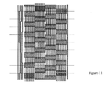
- the read head will servo off orientation PES bursts initially and then off the non-orientation PES bursts. The process of writing PES bursts continues until the write head reaches the OD of the disk (FIG. 11 ).
- the write head may be utilized to erase the media between sectors. This will erase the test marks written earlier and format the data wedges for data storage. Furthermore, at least some of the offsets, such as the radial and/or circumferential offsets, may be measured periodically and adjusted in order to account for any timing changes and actuator arc skew.
- the magnetically written gray code may now be written (FIGS. 12 - 14 ).
- Second patterned servo timing mark 410 is used to signal the start of the magnetically written gray code in this exemplary embodiment.
- the magnetically written gray code may be written circularly around the rotational center of the disk because the disks will typically be mounted in the disk drive such that the servo pattern is eccentric to the rotational center.
- the magnetically written gray code can be written at a higher spatial frequency than that of the patterned gray code and thus may be more area efficient.
- each magnetically written gray code bit is written by pulsing the recording head on the previously erased media.
- FIG. 12 illustrates the sequence that may be used to write the magnetically written gray code.
- Bits 1200 correspond to the D PES bursts
- bits 1202 correspond to B PES bursts
- bits 1204 correspond to C PES bursts
- bits 1206 correspond to A PES bursts.
- each burst in the PES burst fields is rotated through when writing the magnetically written gray code.
- the present invention is not limited to this method.
- the magnetically written gray code can be written in any desired pattern or sequence.
- the magnetically written gray code 1300 may be used to define the track number of the data tracks with no eccentricity (FIG. 13 ).
- bit 1302 depicts a magnetic sync mark.
- Magnetically written gray code bit 1304 corresponds to track 1 .
- Bit 1306 corresponds to track 2 , while bit 1308 corresponds to track 3 .
- the track numbers increase as the tracks move to the OD of the disk, and the corresponding magnetically written gray code bit defines each track number.
- One technique for detecting a side erasure gap is to logically AND a particular gray code bit with the next adjacent gray code bit.
- a second magnetically written gray code 1400 may be written (FIG. 14 ).
- the first 1300 and second 1400 gray codes may be written as two sets of gray code (even and odd) in order to compensate for side erasure gaps in the first gray code set 1300 created by fringe fields from the write head.
- the magnetically written gray code bits may then be detected as the logical OR of the sensed signal in the two locations.
- a flowchart illustrating an exemplary method for initializing patterned media according to the present invention is shown.
- the process begins at block 1500 , and thereafter passes to block 1502 where the patterned media may be DC initialized.
- At least one offset may then be determined, as shown in block 1504 .
- the at least one offset may include an offset to compensate for a read to write delay in the electronics and an offset to compensate for a delay caused by the space separation between the read and write heads (e.g. radial and circumferential offsets).
- the process of writing PES bursts may begin (block 1506 ).
- a determination may then be made at block 1508 as to whether or not all of the PES bursts have been written. If all of the PES bursts have not been written, the previously written PES bursts may be used to determine PES signals (block 1510 ) to guide the write head as new PES burst fields are written (block 1506 ). When all of the PES bursts have been written, the process continues at block 1512 where the magnetically written gray code may be written. The process then ends, as shown in block 1514 .
- FIG. 16 is a block diagram of an exemplary system that may be used to initialize a patterned media according to the present invention.
- At least one read head 1600 and at least one write head 1602 are included in the system.
- the read head 1600 may be connected to the input of a buffer 1604 .
- the output of the buffer may be connected to a data read/write channel 1606 .
- the data read/write channel 1606 may be implemented in any desired manner, such as a modulator that performs a partial response, maximum likelihood encoding.
- the data read/write channel is connected to a channel controller 1608 that may perform a variety of functions.
- the channel controller 1608 may perform zone bit recording, determine clock frequencies, and determine splits across servo sectors.
- the channel controller 1608 is connected to a drive microprocessor controller 1610 , which is connected to a drive interface controller 1612 .
- the drive interface controller 1612 may be implemented in any desired manner.
- One example of a drive interface controller 1612 is a SCSI controller. However, any desired interface controller may be used with the present invention.
- the drive interface controller 1612 connects to a host computer (not shown) via line 1614 .
- the output of buffer 1604 may also be connected to a null mark detector 1616 , a servo timing mark (STM) and interval detector 1618 , and a PES detector 1620 .
- the null mark detector 1616 is used in this exemplary embodiment to detect transitions in the null-type PES pattern. For example, the null mark detector 1616 detects a transition between a DC magnetized A burst and B burst (i.e. Null_N PES) or a transition between a DC magnetized C burst and D burst (Null_Q PES).
- the servo timing mark (STM) and interval detector 1618 may be used to determine the offsets, such as an offset to compensate for read to write delay and at least one offset to compensate for delays caused by the space separation between the read and write heads (e.g. radial and circumferential delays).
- a PES detector 1620 may be used to detect PES bursts.
- the null mark detector 1616 , servo timing mark (STM) and interval detector 1618 , and PES detector 1620 may be configured and implemented in any desired manner.
- the null mark detector 1616 , servo timing mark (STM) and interval detector 1618 , and PES detector may be implemented as hard wired logic within the system.
- the null mark detector 1616 , servo timing mark (STM) and interval detector 1618 , and PES detector may be connected to a DSP controller 1622 , which in turn may be connected to the drive microprocessor controller 1610 .
- a pattern generator with delay 1624 determines a pattern for data, such as the magnetically written gray code.
- a variable delay may be included in order to compensate for the read to write delay in the electronics and the delay caused by the space separation between the read and write heads. The variable delay allows the write head to be positioned over the proper location when writing to the media.
- the pattern generator 1624 is connected to the write head 1602 via buffer 1626 .
- the DSP controller 1622 may be connected to a digital-to-analog converter 1628 .
- the D/A converter 1628 may supply the analog voltage to a servo motor 1630 via buffer 1632 .
- the present invention is not limited to a system having all of these components. In certain embodiments, the systems may include additional components or may be implemented and configured with fewer components than the components shown in FIG. 16 .
Landscapes
- Engineering & Computer Science (AREA)
- Chemical & Material Sciences (AREA)
- Nanotechnology (AREA)
- Physics & Mathematics (AREA)
- Mathematical Physics (AREA)
- Theoretical Computer Science (AREA)
- Crystallography & Structural Chemistry (AREA)
- Moving Of The Head To Find And Align With The Track (AREA)
Abstract
Description
Claims (21)
Priority Applications (1)
| Application Number | Priority Date | Filing Date | Title |
|---|---|---|---|
| US09/863,394 US6751035B1 (en) | 1999-06-08 | 2001-05-23 | Method and system for initializing patterned media |
Applications Claiming Priority (10)
| Application Number | Priority Date | Filing Date | Title |
|---|---|---|---|
| US13825599P | 1999-06-08 | 1999-06-08 | |
| US13825699P | 1999-06-08 | 1999-06-08 | |
| US13825799P | 1999-06-08 | 1999-06-08 | |
| US13825899P | 1999-06-08 | 1999-06-08 | |
| US14348299P | 1999-07-12 | 1999-07-12 | |
| US15012299P | 1999-08-20 | 1999-08-20 | |
| US15012399P | 1999-08-20 | 1999-08-20 | |
| US20674700P | 2000-05-24 | 2000-05-24 | |
| US59159600A | 2000-06-08 | 2000-06-08 | |
| US09/863,394 US6751035B1 (en) | 1999-06-08 | 2001-05-23 | Method and system for initializing patterned media |
Related Parent Applications (1)
| Application Number | Title | Priority Date | Filing Date |
|---|---|---|---|
| US59159600A Continuation-In-Part | 1999-06-08 | 2000-06-08 |
Publications (1)
| Publication Number | Publication Date |
|---|---|
| US6751035B1 true US6751035B1 (en) | 2004-06-15 |
Family
ID=32398481
Family Applications (1)
| Application Number | Title | Priority Date | Filing Date |
|---|---|---|---|
| US09/863,394 Expired - Lifetime US6751035B1 (en) | 1999-06-08 | 2001-05-23 | Method and system for initializing patterned media |
Country Status (1)
| Country | Link |
|---|---|
| US (1) | US6751035B1 (en) |
Cited By (25)
| Publication number | Priority date | Publication date | Assignee | Title |
|---|---|---|---|---|
| US20050272797A1 (en) * | 2000-08-08 | 2005-12-08 | Daiichi Pharmaceutical Co., Ltd. | Processes for preparation of bicyclic compounds and intermediates therefor |
| US20060092541A1 (en) * | 2004-10-29 | 2006-05-04 | Andreas Moser | Magnetic recording disk drive with patterned media and circuit for generating timing pulses from the pattern |
| US20060279871A1 (en) * | 2005-06-09 | 2006-12-14 | Albrecht Thomas R | Method for formatting a magnetic recording disk with patterned nondata islands of alternating polarity |
| US20060280861A1 (en) * | 2005-04-19 | 2006-12-14 | Kabushiki Kaisha Toshiba | Method for producing magnetic recording medium |
| US20060280975A1 (en) * | 2005-06-09 | 2006-12-14 | Albrecht Thomas R | Magnetic recording disk with patterned nondata islands of alternating polarity |
| US20070217075A1 (en) * | 2006-03-16 | 2007-09-20 | Kabushiki Kaisha Toshiba | Patterned media and method of manufacturing the same, and magnetic recording apparatus |
| US20070230055A1 (en) * | 2006-03-30 | 2007-10-04 | Kabushiki Kaisha Toshiba | Magnetic recording media, magnetic recording apparatus, and method for manufacturing magnetic recording media |
| US7345838B2 (en) | 2004-08-06 | 2008-03-18 | Kabushiki Kaisha Toshiba | Magnetic recording media and magnetic recording and reproducing apparatus |
| US20080144452A1 (en) * | 2006-12-15 | 2008-06-19 | Seagate Technology Llc | Compensating the effects of non-synchronous writing of erasable servo marks |
| US20080239906A1 (en) * | 2007-03-26 | 2008-10-02 | Kyo Akagi | Magnetic recording media, method for servowriting on same, and hard disk drive |
| US20080285174A1 (en) * | 2007-05-14 | 2008-11-20 | Kabushiki Kaisha Toshiba | Magnetic recording medium and magnetic storage device |
| US20090002865A1 (en) * | 2007-06-28 | 2009-01-01 | Seagate Technology Llc | Zone Based Timing Recovery For Bit Patterned Media |
| US20090009901A1 (en) * | 2007-07-03 | 2009-01-08 | Seagate Technology Llc | Retry and re-read for write synchronization |
| US20090040652A1 (en) * | 2007-08-11 | 2009-02-12 | Hitachi Global Storage Technologies Netherlands B.V. | Magnetic recording disk and disk drive with patterned phase-type servo fields for read/write head positioning |
| US20090059412A1 (en) * | 2007-09-05 | 2009-03-05 | Seagate Technology Llc | Extracting Position Information Using User Data |
| US20090081482A1 (en) * | 2007-09-26 | 2009-03-26 | Kabushiki Kaisha Toshiba | Magnetic recording medium and method of manufacturing the same |
| US20090086356A1 (en) * | 2007-10-02 | 2009-04-02 | Seagate Technology Llc | Detecting and Correcting Insertion and Deletion of Bits for Bit Patterned Media Storage Systems |
| US20090195916A1 (en) * | 2008-02-04 | 2009-08-06 | Seagate Technology Llc | Extraction of transducer position information from bit patterned magnetic media |
| US20100128583A1 (en) * | 2008-11-26 | 2010-05-27 | Htachi Global Storage Technologies Netherlands B.V. | Method for servowriting a patterned-media perpendicular magnetic recording disk using position error signal (pes) alignment fields |
| US20100195235A1 (en) * | 2009-02-03 | 2010-08-05 | Seagate Technology Llc | Measurement of track eccentricity on bit patterned media |
| US7944643B1 (en) | 2007-12-05 | 2011-05-17 | Wd Media, Inc. | Patterns for pre-formatted information on magnetic hard disk media |
| US8000053B1 (en) | 2008-12-23 | 2011-08-16 | Western Digital Technologies, Inc. | Write jog value determination for a disk drive |
| US20120075740A1 (en) * | 2010-03-31 | 2012-03-29 | Wd Media (Singapore) Pte. Ltd. | Thermally Assisted Magnetic Recording Disk, Manufacturing Method Thereof, And Magnetic Recording Method |
| US8305705B1 (en) | 2010-05-05 | 2012-11-06 | Western Digital Technologies, Inc. | Disk drive cross correlating track crossing signal with ideal signal to calibrate jog value |
| US8665549B2 (en) | 2011-09-29 | 2014-03-04 | HGST Netherlands B.V. | Method for creating burst magnitude servo patterns with unipolar bits on a magnetic media of a magnetic data recording system |
Citations (6)
| Publication number | Priority date | Publication date | Assignee | Title |
|---|---|---|---|---|
| US5165082A (en) * | 1988-09-20 | 1992-11-17 | Jujitsu Limited | Method for writing servo signals on a servo disk in a magnetic disk apparatus |
| US5987634A (en) * | 1994-11-17 | 1999-11-16 | Cirrus Logic, Inc. | Channel quality circuit in a sampled amplitude read channel |
| US6154330A (en) * | 1997-09-17 | 2000-11-28 | Alps Electric Co., Ltd. | Disk provided with servo patterns and method of recording servo patterns |
| US6476992B1 (en) * | 1999-07-08 | 2002-11-05 | Fujitsu Limited | Magnetic disk apparatus and optimum offset measuring method |
| US6510015B2 (en) * | 1999-12-10 | 2003-01-21 | Seagate Technology Llc | Magnetic disc having physical servo patterns with a magnetic carrier, and method of making and using the same |
| US6643082B1 (en) * | 1999-06-08 | 2003-11-04 | Seagate Technology Llc | Servo sector format for a patterned media |
-
2001
- 2001-05-23 US US09/863,394 patent/US6751035B1/en not_active Expired - Lifetime
Patent Citations (6)
| Publication number | Priority date | Publication date | Assignee | Title |
|---|---|---|---|---|
| US5165082A (en) * | 1988-09-20 | 1992-11-17 | Jujitsu Limited | Method for writing servo signals on a servo disk in a magnetic disk apparatus |
| US5987634A (en) * | 1994-11-17 | 1999-11-16 | Cirrus Logic, Inc. | Channel quality circuit in a sampled amplitude read channel |
| US6154330A (en) * | 1997-09-17 | 2000-11-28 | Alps Electric Co., Ltd. | Disk provided with servo patterns and method of recording servo patterns |
| US6643082B1 (en) * | 1999-06-08 | 2003-11-04 | Seagate Technology Llc | Servo sector format for a patterned media |
| US6476992B1 (en) * | 1999-07-08 | 2002-11-05 | Fujitsu Limited | Magnetic disk apparatus and optimum offset measuring method |
| US6510015B2 (en) * | 1999-12-10 | 2003-01-21 | Seagate Technology Llc | Magnetic disc having physical servo patterns with a magnetic carrier, and method of making and using the same |
Cited By (48)
| Publication number | Priority date | Publication date | Assignee | Title |
|---|---|---|---|---|
| US20050272797A1 (en) * | 2000-08-08 | 2005-12-08 | Daiichi Pharmaceutical Co., Ltd. | Processes for preparation of bicyclic compounds and intermediates therefor |
| CN100411018C (en) * | 2004-08-06 | 2008-08-13 | 株式会社东芝 | Magnetic recording media and magnetic recording and reproducing apparatus |
| US7345838B2 (en) | 2004-08-06 | 2008-03-18 | Kabushiki Kaisha Toshiba | Magnetic recording media and magnetic recording and reproducing apparatus |
| US7324294B2 (en) | 2004-10-29 | 2008-01-29 | Hitachi Global Storage Technologies Netherlands B.V. | Magnetic recording disk drive with patterned media and circuit for generating timing pulses from the pattern |
| US20060092541A1 (en) * | 2004-10-29 | 2006-05-04 | Andreas Moser | Magnetic recording disk drive with patterned media and circuit for generating timing pulses from the pattern |
| US20060280861A1 (en) * | 2005-04-19 | 2006-12-14 | Kabushiki Kaisha Toshiba | Method for producing magnetic recording medium |
| US7662264B2 (en) | 2005-04-19 | 2010-02-16 | Kabushiki Kaisha Toshiba | Method for producing magnetic recording medium |
| US7771852B2 (en) | 2005-06-09 | 2010-08-10 | Hitachi Global Storage Technologies Netherlands B.V. | Magnetic recording disk with patterned nondata islands of alternating polarity |
| US20060279871A1 (en) * | 2005-06-09 | 2006-12-14 | Albrecht Thomas R | Method for formatting a magnetic recording disk with patterned nondata islands of alternating polarity |
| US7236325B2 (en) | 2005-06-09 | 2007-06-26 | Hitachi Global Storage Technologies Netherlands B.V. | Method for formatting a magnetic recording disk with patterned nondata islands of alternating polarity |
| US20060280975A1 (en) * | 2005-06-09 | 2006-12-14 | Albrecht Thomas R | Magnetic recording disk with patterned nondata islands of alternating polarity |
| US8257560B2 (en) | 2006-03-16 | 2012-09-04 | Kabushiki Kaisha Toshiba | Patterned media and method of manufacturing the same, and magnetic recording apparatus |
| US20070217075A1 (en) * | 2006-03-16 | 2007-09-20 | Kabushiki Kaisha Toshiba | Patterned media and method of manufacturing the same, and magnetic recording apparatus |
| US7898768B2 (en) | 2006-03-16 | 2011-03-01 | Kabushiki Kaisha Toshiba | Patterned medium with magnetic pattern depth relationship |
| US20110011830A1 (en) * | 2006-03-30 | 2011-01-20 | Kabushiki Kaisha Toshiba | Magnetic Recording Media, Magnetic Recording Apparatus, and Method for Manufacturing Magnetic Recording Media |
| US20070230055A1 (en) * | 2006-03-30 | 2007-10-04 | Kabushiki Kaisha Toshiba | Magnetic recording media, magnetic recording apparatus, and method for manufacturing magnetic recording media |
| US7826176B2 (en) | 2006-03-30 | 2010-11-02 | Kabushiki Kaisha Toshiba | Magnetic recording medium with thicker protective film in edge areas and magnetic recording apparatus using the medium |
| US8023392B2 (en) * | 2006-12-15 | 2011-09-20 | Seagate Technology Llc | Compensating the effects of non-synchronous writing of erasable servo marks |
| US20080144452A1 (en) * | 2006-12-15 | 2008-06-19 | Seagate Technology Llc | Compensating the effects of non-synchronous writing of erasable servo marks |
| US8482877B2 (en) * | 2007-03-26 | 2013-07-09 | HGST Netherlands B.V. | Magnetic recording media, method for servowriting on same, and hard disk drive |
| US20080239906A1 (en) * | 2007-03-26 | 2008-10-02 | Kyo Akagi | Magnetic recording media, method for servowriting on same, and hard disk drive |
| US20080285174A1 (en) * | 2007-05-14 | 2008-11-20 | Kabushiki Kaisha Toshiba | Magnetic recording medium and magnetic storage device |
| US8049993B2 (en) | 2007-05-14 | 2011-11-01 | Kabushiki Kaisha Toshiba | Magnetic recording medium and magnetic storage device |
| US20090002865A1 (en) * | 2007-06-28 | 2009-01-01 | Seagate Technology Llc | Zone Based Timing Recovery For Bit Patterned Media |
| US7729074B2 (en) | 2007-06-28 | 2010-06-01 | Seagate Technology Llc | Zone based timing recovery for bit patterned media |
| US20090009901A1 (en) * | 2007-07-03 | 2009-01-08 | Seagate Technology Llc | Retry and re-read for write synchronization |
| US7667912B2 (en) | 2007-07-03 | 2010-02-23 | Seagate Technology Llc | Retry and re-read for write synchronization |
| US20090040652A1 (en) * | 2007-08-11 | 2009-02-12 | Hitachi Global Storage Technologies Netherlands B.V. | Magnetic recording disk and disk drive with patterned phase-type servo fields for read/write head positioning |
| US7848039B2 (en) * | 2007-08-11 | 2010-12-07 | Hitachi Global Storage Technologies Netherlands B.V. | Magnetic recording disk and disk drive with patterned phase-type servo fields for read/write head positioning |
| US7688535B2 (en) | 2007-09-05 | 2010-03-30 | Seagate Technology Llc | Extracting position information using user data |
| US20090059412A1 (en) * | 2007-09-05 | 2009-03-05 | Seagate Technology Llc | Extracting Position Information Using User Data |
| US8338007B2 (en) | 2007-09-26 | 2012-12-25 | Kabushiki Kaisha Toshiba | Magnetic recording medium and magnetic recording apparatus |
| US8652338B2 (en) | 2007-09-26 | 2014-02-18 | Kabushiki Kaisha Toshiba | Magnetic recording medium and method of manufacturing the same |
| US20090081482A1 (en) * | 2007-09-26 | 2009-03-26 | Kabushiki Kaisha Toshiba | Magnetic recording medium and method of manufacturing the same |
| US20090086356A1 (en) * | 2007-10-02 | 2009-04-02 | Seagate Technology Llc | Detecting and Correcting Insertion and Deletion of Bits for Bit Patterned Media Storage Systems |
| US7787205B2 (en) | 2007-10-02 | 2010-08-31 | Seagate Technology Llc | Detecting and correcting insertion and deletion of bits for bit patterned media storage systems |
| US7944643B1 (en) | 2007-12-05 | 2011-05-17 | Wd Media, Inc. | Patterns for pre-formatted information on magnetic hard disk media |
| US7957084B2 (en) | 2008-02-04 | 2011-06-07 | Seagate Technology Llc | Extraction of transducer position information from bit patterned magnetic media |
| US20090195916A1 (en) * | 2008-02-04 | 2009-08-06 | Seagate Technology Llc | Extraction of transducer position information from bit patterned magnetic media |
| US20100128583A1 (en) * | 2008-11-26 | 2010-05-27 | Htachi Global Storage Technologies Netherlands B.V. | Method for servowriting a patterned-media perpendicular magnetic recording disk using position error signal (pes) alignment fields |
| US7911728B2 (en) | 2008-11-26 | 2011-03-22 | Hitachi Global Storage Technologies Netherlands B.V. | Method for servowriting a patterned-media perpendicular magnetic recording disk using position error signal (PES) alignment fields |
| US8000053B1 (en) | 2008-12-23 | 2011-08-16 | Western Digital Technologies, Inc. | Write jog value determination for a disk drive |
| US8045282B2 (en) | 2009-02-03 | 2011-10-25 | Seagate Technology Llc | Measurement of track eccentricity on bit patterned media |
| US20100195235A1 (en) * | 2009-02-03 | 2010-08-05 | Seagate Technology Llc | Measurement of track eccentricity on bit patterned media |
| US20120075740A1 (en) * | 2010-03-31 | 2012-03-29 | Wd Media (Singapore) Pte. Ltd. | Thermally Assisted Magnetic Recording Disk, Manufacturing Method Thereof, And Magnetic Recording Method |
| US8634155B2 (en) * | 2010-03-31 | 2014-01-21 | Wd Media (Singapore) Pte. Ltd. | Thermally assisted magnetic recording disk with ion-implant facilitated non-magnetic regions, manufacturing method thereof, and magnetic recording method |
| US8305705B1 (en) | 2010-05-05 | 2012-11-06 | Western Digital Technologies, Inc. | Disk drive cross correlating track crossing signal with ideal signal to calibrate jog value |
| US8665549B2 (en) | 2011-09-29 | 2014-03-04 | HGST Netherlands B.V. | Method for creating burst magnitude servo patterns with unipolar bits on a magnetic media of a magnetic data recording system |
Similar Documents
| Publication | Publication Date | Title |
|---|---|---|
| US6751035B1 (en) | Method and system for initializing patterned media | |
| US6643082B1 (en) | Servo sector format for a patterned media | |
| US6490111B1 (en) | Method and apparatus for refreshing servo patterns in a disc drive | |
| US6738207B1 (en) | Method for synchronizing the write current for magnetic recording with the bit islands on discrete bit patterned media | |
| JP2694850B2 (en) | Servo address device | |
| US4935835A (en) | Magnetic media containing reference feature and methods for referencing magnetic head position to the reference feature | |
| US7746594B1 (en) | Disk drive comprising slanted line servo burst sets offset radially | |
| EP0560282B1 (en) | Servo system for providing increased recording density and improved operation of the AGC circuitry | |
| US6961203B1 (en) | Hybrid printed servo patterns for magnetic media and hard disk systems implementing same | |
| US7746595B1 (en) | Disk drive comprising slanted line servo bursts having reverse polarity segments | |
| EP0339851A2 (en) | A magnetic record disk with embedded servo information | |
| US5771126A (en) | Hard disk drive with reduced sized servo sectors and driving method therefor | |
| US7158330B2 (en) | Method and apparatus for servo track writing by track following on a dedicated servo disk on a fluid spindle bearing | |
| US7466506B1 (en) | Magnetic recording disk drive with head positioning servo control system for disk surfaces with identical servo patterns | |
| US6219197B1 (en) | Method and apparatus for servo positioning in a direct access storage device with a transducer read element width greater than ⅓ and less than ½ width of a data cylinder | |
| US7054092B2 (en) | Methods for improving printed media self-servo writing | |
| JP3446289B2 (en) | Disk drive | |
| JP4227004B2 (en) | Servo tracking pattern writing method | |
| US20050275963A1 (en) | Variable frequency chevron in printed media reference pattern to improve servo demodulation | |
| US5801897A (en) | Head positioning control system for use in a disk storage system | |
| JP3099133B2 (en) | Method of forming servo data | |
| EP0645764A2 (en) | Method and apparatus for phase modulated servo positioning in a direct access storage device | |
| US7095580B2 (en) | Methods to determine gross and fine positioning on a reference surface of a media | |
| JP3910736B2 (en) | Disk storage device and servo sector address error detection method in the same device | |
| US11568894B1 (en) | Reducing the effect of spiral sync marks in non-coherent repeatable runout |
Legal Events
| Date | Code | Title | Description |
|---|---|---|---|
| AS | Assignment |
Owner name: SEAGATE TECHNOLOGY LLC, CALIFORNIA Free format text: ASSIGNMENT OF ASSIGNORS INTEREST;ASSIGNOR:BELSER, KARL A.;REEL/FRAME:011841/0507 Effective date: 20010509 |
|
| AS | Assignment |
Owner name: JPMORGAN CHASE BANK, AS COLLATERAL AGENT, NEW YORK Free format text: SECURITY AGREEMENT;ASSIGNOR:SEAGATE TECHNOLOGY LLC;REEL/FRAME:013177/0001 Effective date: 20020513 Owner name: JPMORGAN CHASE BANK, AS COLLATERAL AGENT,NEW YORK Free format text: SECURITY AGREEMENT;ASSIGNOR:SEAGATE TECHNOLOGY LLC;REEL/FRAME:013177/0001 Effective date: 20020513 |
|
| STCF | Information on status: patent grant |
Free format text: PATENTED CASE |
|
| AS | Assignment |
Owner name: SEAGATE TECHNOLOGY LLC, CALIFORNIA Free format text: RELEASE OF SECURITY INTERESTS IN PATENT RIGHTS;ASSIGNOR:JPMORGAN CHASE BANK, N.A. (FORMERLY KNOWN AS THE CHASE MANHATTAN BANK AND JPMORGAN CHASE BANK), AS ADMINISTRATIVE AGENT;REEL/FRAME:016958/0607 Effective date: 20051130 |
|
| FPAY | Fee payment |
Year of fee payment: 4 |
|
| REMI | Maintenance fee reminder mailed | ||
| AS | Assignment |
Owner name: JPMORGAN CHASE BANK, N.A., AS ADMINISTRATIVE AGENT Free format text: SECURITY AGREEMENT;ASSIGNORS:MAXTOR CORPORATION;SEAGATE TECHNOLOGY LLC;SEAGATE TECHNOLOGY INTERNATIONAL;REEL/FRAME:022757/0017 Effective date: 20090507 Owner name: WELLS FARGO BANK, NATIONAL ASSOCIATION, AS COLLATE Free format text: SECURITY AGREEMENT;ASSIGNORS:MAXTOR CORPORATION;SEAGATE TECHNOLOGY LLC;SEAGATE TECHNOLOGY INTERNATIONAL;REEL/FRAME:022757/0017 Effective date: 20090507 |
|
| AS | Assignment |
Owner name: MAXTOR CORPORATION, CALIFORNIA Free format text: RELEASE;ASSIGNOR:JPMORGAN CHASE BANK, N.A., AS ADMINISTRATIVE AGENT;REEL/FRAME:025662/0001 Effective date: 20110114 Owner name: SEAGATE TECHNOLOGY LLC, CALIFORNIA Free format text: RELEASE;ASSIGNOR:JPMORGAN CHASE BANK, N.A., AS ADMINISTRATIVE AGENT;REEL/FRAME:025662/0001 Effective date: 20110114 Owner name: SEAGATE TECHNOLOGY HDD HOLDINGS, CALIFORNIA Free format text: RELEASE;ASSIGNOR:JPMORGAN CHASE BANK, N.A., AS ADMINISTRATIVE AGENT;REEL/FRAME:025662/0001 Effective date: 20110114 Owner name: SEAGATE TECHNOLOGY INTERNATIONAL, CALIFORNIA Free format text: RELEASE;ASSIGNOR:JPMORGAN CHASE BANK, N.A., AS ADMINISTRATIVE AGENT;REEL/FRAME:025662/0001 Effective date: 20110114 |
|
| AS | Assignment |
Owner name: THE BANK OF NOVA SCOTIA, AS ADMINISTRATIVE AGENT, Free format text: SECURITY AGREEMENT;ASSIGNOR:SEAGATE TECHNOLOGY LLC;REEL/FRAME:026010/0350 Effective date: 20110118 |
|
| FPAY | Fee payment |
Year of fee payment: 8 |
|
| AS | Assignment |
Owner name: SEAGATE TECHNOLOGY US HOLDINGS, INC., CALIFORNIA Free format text: TERMINATION AND RELEASE OF SECURITY INTEREST IN PATENT RIGHTS;ASSIGNOR:WELLS FARGO BANK, NATIONAL ASSOCIATION, AS COLLATERAL AGENT AND SECOND PRIORITY REPRESENTATIVE;REEL/FRAME:030833/0001 Effective date: 20130312 Owner name: EVAULT INC. (F/K/A I365 INC.), CALIFORNIA Free format text: TERMINATION AND RELEASE OF SECURITY INTEREST IN PATENT RIGHTS;ASSIGNOR:WELLS FARGO BANK, NATIONAL ASSOCIATION, AS COLLATERAL AGENT AND SECOND PRIORITY REPRESENTATIVE;REEL/FRAME:030833/0001 Effective date: 20130312 Owner name: SEAGATE TECHNOLOGY INTERNATIONAL, CAYMAN ISLANDS Free format text: TERMINATION AND RELEASE OF SECURITY INTEREST IN PATENT RIGHTS;ASSIGNOR:WELLS FARGO BANK, NATIONAL ASSOCIATION, AS COLLATERAL AGENT AND SECOND PRIORITY REPRESENTATIVE;REEL/FRAME:030833/0001 Effective date: 20130312 Owner name: SEAGATE TECHNOLOGY LLC, CALIFORNIA Free format text: TERMINATION AND RELEASE OF SECURITY INTEREST IN PATENT RIGHTS;ASSIGNOR:WELLS FARGO BANK, NATIONAL ASSOCIATION, AS COLLATERAL AGENT AND SECOND PRIORITY REPRESENTATIVE;REEL/FRAME:030833/0001 Effective date: 20130312 |
|
| FPAY | Fee payment |
Year of fee payment: 12 |