US6721128B1 - Closure seal for a storage device - Google Patents
Closure seal for a storage device Download PDFInfo
- Publication number
- US6721128B1 US6721128B1 US08/997,621 US99762197A US6721128B1 US 6721128 B1 US6721128 B1 US 6721128B1 US 99762197 A US99762197 A US 99762197A US 6721128 B1 US6721128 B1 US 6721128B1
- Authority
- US
- United States
- Prior art keywords
- cover
- base
- recited
- hole
- sheet seal
- Prior art date
- Legal status (The legal status is an assumption and is not a legal conclusion. Google has not performed a legal analysis and makes no representation as to the accuracy of the status listed.)
- Expired - Fee Related
Links
Images


Classifications
-
- G—PHYSICS
- G11—INFORMATION STORAGE
- G11B—INFORMATION STORAGE BASED ON RELATIVE MOVEMENT BETWEEN RECORD CARRIER AND TRANSDUCER
- G11B33/00—Constructional parts, details or accessories not provided for in the other groups of this subclass
- G11B33/14—Reducing influence of physical parameters, e.g. temperature change, moisture, dust
- G11B33/1446—Reducing contamination, e.g. by dust, debris
- G11B33/1466—Reducing contamination, e.g. by dust, debris sealing gaskets
-
- G—PHYSICS
- G11—INFORMATION STORAGE
- G11B—INFORMATION STORAGE BASED ON RELATIVE MOVEMENT BETWEEN RECORD CARRIER AND TRANSDUCER
- G11B25/00—Apparatus characterised by the shape of record carrier employed but not specific to the method of recording or reproducing, e.g. dictating apparatus; Combinations of such apparatus
- G11B25/04—Apparatus characterised by the shape of record carrier employed but not specific to the method of recording or reproducing, e.g. dictating apparatus; Combinations of such apparatus using flat record carriers, e.g. disc, card
- G11B25/043—Apparatus characterised by the shape of record carrier employed but not specific to the method of recording or reproducing, e.g. dictating apparatus; Combinations of such apparatus using flat record carriers, e.g. disc, card using rotating discs
Definitions
- the present invention relates to a storage device for storing computer data, such as a magnetic disk storage device, an optical disk storage device, or the like, and, more particularly, the present invention relates to a computer storage device having a closure seal to block the flow of air into and out of the storage device, which closure seal is reliably affixed and has an increased degree of sealing.
- the flotation characteristics of the heads are adversely affected by even a small amount of dust.
- the adverse affects on the flotation characteristics of the heads caused by dust include running away of the heads, or collision of the heads with the disk, thereby damaging the heads or the disk, decreasing the process efficiency of data transfer, and thus decreasing the reliability of the storage device. Accordingly, it is desired to reliably perform sealing of disk storage devices, particularly disk storage devices having higher density tracks.
- the conventional magnetic disk storage device consists of a housing (casing) having a base on which the components of the magnetic disk device are situated, and a cover superposed on the base to cover the base.
- packing is inserted in a boundary portion between the base and the cover.
- the base and the cover are made integral by connecting the base and cover via screws passed through screw holes in the cover and the base.
- the screw holes are disposed in screw hole grooves formed by a step down from the cover surface so that the screw heads do not project from the cover surface. After tightening the screws, a closure seal somewhat larger than the size of the screw hole groove is affixed to each screw hole groove to cover the screw hole grooves.
- a storage device suitable for storing computer data, comprising a base to support a mechanism for accessing a storage medium; a cover to cover the base, the cover including an aperture; and a closure seal comprised of a single sheet to seal a boundary of the base and the cover, and to seal the aperture of the cover.
- a plurality of positions of the storage device are sealed using a single sheet closure seal, and the operability of the storage device is increased. Furthermore, the flatness of the surface to which the closure seal is affixed is increased.
- the closure seal may comprise a single sheet to cover the entire surface of the cover and the base adjacent the boundary of the base and the cover.
- the aperture may comprise a hole, or a groove provided with a hole, in which a screw is inserted.
- the cover may include a plurality of apertures.
- the closure seal may comprise a ventilation hole in a position separated from the boundary and the aperture. Further, the closure seal may comprise a plurality of ventilation holes.
- the storage device further comprises a member to which the closure seal is affixed, and the member includes a ventilation hole in a surface to which the closure seal is affixed. Further, the member may comprise a plurality of ventilation holes in the surface to which the closure seal is affixed.
- the closure seal is affixed to a surface of the cover, and the cover comprises a ventilation hole in the surface to which the closure seal is affixed.
- the cover may comprise a plurality of ventilation holes.
- the storage device further comprises a damping plate on a surface of the cover or on a surface of the base, and the damping plate includes a ventilation hole in the surface to which the closure seal is affixed.
- the damping plate may include a plurality of ventilation holes in the surface to which the closure seal is affixed.
- the closure seal when affixing the closure seal, the closure seal is pressed to a surface to which it is affixed and air escapes through the ventilation holes.
- the escape of air through the ventilation holes the formation of air bubbles is advantageously prevented and the durability of the closure seal is increased.
- an increased flatness of the surface to which the closure seal is affixed can be advantageously achieved.
- the ventilation holes are disposed in positions separated by at least 1 millimeter (mm) from the boundary of the base and cover, and/or from the aperture. Accordingly, there is no loss of sealing, the formation of bubbles is prevented, and the durability of the closure seal is increased.
- the ventilation holes have a one of a circular, polygonal or cross-shaped configuration. Accordingly, the ventilation holes are formed without any adverse effects on the strength and durability of the closure seal.
- the cover fits into an inner peripheral surface of an upper portion of the base, and an upper end surface of the cover and an upper end surface of the base have dimensions which together form a flat surface for affixing the closure seal. Accordingly, by making the difference in level between the upper end surface of the cover and upper end surface of the base small or none at the boundary of the base and cover, the closure seal is flat at the boundary position of the base and cover, and the durability of the closure seal is increased.
- a storage device comprising a base to support a mechanism for accessing a storage medium, the base including an aperture; a cover to cover the base, the cover including an aperture; and a closure seal comprising a single sheet to seal an aperture of the base and/or the cover, wherein the closure seal includes a ventilation hole in a position separated from the apertures.
- the base may include a plurality of apertures.
- the cover may include a plurality of apertures, and a plurality of ventilation holes separated from the apertures.
- the ventilation holes are positioned away from markings on the closure seal, such as characters, symbols, or diagrams. Accordingly, the formation of air bubbles in the closure seal is prevented without obscuring the characters, symbols or diagrams, and the durability of the closure seal is increased.
- a storage device comprising a base to support a mechanism for accessing a storage medium, the base including an aperture; a cover to cover the base, the cover including an aperture; a closure seal comprising one sheet to seal an aperture of the base and/or the cover, wherein the closure seal is affixed to a surface having a ventilation hole.
- the storage device further comprises a damping on one of the cover or the base, and the closure seal is affixed to one of the cover, the base, the damping plate, or components exposed to the exterior from the cover or the base.
- the formation of air bubbles is prevented without any loss of sealing, the surface to which the closure seal is affixed is flattened, and the durability of the closure seal is increased.
- the storage device further comprises a reinforcing plate member, and the reinforcing plate member has at least one through hole disposed on the inside surface opposite the aperture.
- the reinforcing plate member is preferably a film made of metal or plastic.
- the strength of the closure seal is reinforced, the formation of air bubbles is prevented and the durability of the closure seal is increased.
- the reinforcing plate member is easily made from sheet metal by press technology.
- the reinforcing plate member can easily be made of natural rubber and the like resins or formed by synthetic plastics technology by molding or cutting.
- FIG. 1 is an exploded oblique view of a magnetic disk device in accordance with a first embodiment of the present invention.
- FIG. 2A is an overall oblique view of the magnetic disk device shown in FIG. 1 in accordance with the first embodiment of the present invention.
- FIG. 2B is a cross sectional diagram in the length direction of the magnetic disk device shown in FIG. 1 in accordance with the first embodiment of the present invention.
- FIG. 3A is a perspective view of a magnetic disk device having a closure seal in accordance with a second embodiment of the present invention.
- FIG. 3B is a diagram of the closure seal in accordance with the second embodiment of the present invention.
- FIG. 4A is a perspective view of a magnetic disk device having a closure seal in accordance with a modification of the second embodiment of the present invention.
- FIG. 4B is a diagram illustrating the closure seal in accordance with the modification of the second embodiment of the present invention.
- FIG. 5 is an exploded oblique view of a magnetic disk device in accordance with the third embodiment of the present invention.
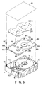
- FIG. 6 is an exploded oblique view of a magnetic disk device in accordance with the fourth embodiment of the present invention.
- FIG. 7 is an exploded oblique view of a magnetic disk device in accordance with a fifth embodiment of the present invention.
- the storage device is preferably a magnetic disk storage device.
- the present invention is not limited in application to a magnetic disk storage device, and the present invention is also applicable to other types of disk storage devices, such as optical disks, and the like.
- FIG. 1 is an exploded oblique view of a magnetic disk device in accordance with the first embodiment of the present invention.
- FIG. 2A is an overall oblique diagram of the magnetic disk device shown in FIG. 1
- FIG. 2B is a cross sectional diagram in the length direction of the magnetic disk device shown in FIG. 1 .
- the magnetic disk device 40 includes a housing (casing) having a base 1 , which supports and contains the magnetic disk device 40 components, and a cover 7 to cover the base 1 .
- the base 1 is formed as a deep bathtub type molding in order to provide the space within the base 1 in which the magnetic disk device 40 components are received.
- the components received within the base 1 include a spindle motor 3 to drive ten ( 10 ) disks 2 at about 6,000 rpm, an actuator arm 5 to suspend read/write heads 6 which write signals onto the disks 2 and read signals from the disks 2 , and a voice coil motor 4 including coils 4 a and magnetic circuit units 4 b to drive the actuator arm 5 .
- the cover 7 is a thin sheet including a plurality of grooves 8 A formed in a peripheral surface 7 C by press technology. Screw through holes 8 B, 3 C and 5 B are formed in a center portion of the respective grooves 8 A through which screws 8 C are inserted.
- the top of the spindle motor 3 and the top of a shaft 5 A of the actuator arm 5 each have a greater height than the other components supported on the base 1 .
- the receiving space of the housing is maintained by positioning the top of the spindle motor 3 and the top of the shaft 5 A to respectively face protruding surfaces 7 A of the cover 7 .
- respective screw holes 3 C, 5 B are formed in a shaft 3 B of the spindle motor 3 and in the shaft 5 A of the actuator arm 5 , and are connected with screws via the screw holes in the grooves 8 A of the cover 7 and via the screw holes 3 C and 5 B.
- the cover 7 includes a surface 7 B peripheral to the protruding surface 7 A and at a level different from the protruding surface 7 A (surfaces 7 A and 7 C are at the same level).
- a damping plate 10 comprising a rolled steel plate is affixed to the cover 7 by an adhesive or tackifier via a vibration absorbing material (VEM).
- the damping plate 10 is shaped to cover the periphery of the upper portions of the spindle motor 3 and the actuator arm 5 , and prevents vibration of the spindle motor 3 and the actuator arm 5 , thereby preventing generation of vibration noise.
- the cover 7 is formed to fit into the inner peripheral surface of the base 1 . More particularly, mounting surfaces 1 E are disposed on wall portions of the base 1 at a level which is lower than an upper surface 1 A of the base 1 by the thickness of the cover 7 . Further, the external form of the cover 7 is smaller than the internal form of the base 1 , and, as shown in FIG. 2B, when the cover 7 is mounted in the base 1 the upper surface 1 A of the base 1 is at the same level as the cover 7 and is exposed in an unobstructed manner.
- the upper end surface of the cover 7 does not project upward from the upper end surface 1 A of the base 1 . Accordingly, the upper end surface of the cover 7 and the upper end surface 1 A of the base 1 are about the same height. Moreover, the upper end surface of the damping plate 10 also does not project beyond the upper end surface 1 A of the base 1 , and the respective levels of the damping plate 10 and the cover surface 7 B are at about the same height.
- the magnetic disk device shown in FIGS. 1, 2 A and 2 B in accordance with the first embodiment of the present invention provides ease of operation of affixing a closure seal 41 . Further, the formation of air bubbles due to differences in level, or failure of the closure seal 41 , can be prevented. Moreover, because the screw engagement surfaces around the screw holes are disposed lower than the surfaces of the protruding surfaces 7 A, 7 C, the screw heads do not protrude from the surfaces of the protruding surfaces 7 A, 7 C, and the screw heads do not protrude above the upper end surface 1 A of the base 1 .
- the cover 7 is not limited to a cover having screw hole grooves 8 A, and the cover 7 can be attached to the base 1 using dish screws without disposing screw hole grooves 8 A in the cover 7 .
- dish screws are used to attach the cover 7 , there is practically no protrusion because the screw heads of the dish screws have a flat dish form. Therefore, it is possible to affix the closure seal 41 directly on the screw heads.
- An aperture 48 is formed in a bottom surface of the base 1 through which a connector (not shown) fits for leading a flexible printed sheet 47 out to the exterior of the housing to conduct signals of the heads 6 .
- the connector fitted in the aperture 48 is coupled to a connector (not shown) on a printed circuit board 49 , disposed outside the base 1 , on which a circuit is formed to perform servo control, signal processing and the like.
- a closure seal 41 is affixed to the housing.
- the closure seal 41 is a single sheet through which air does not pass and has a size to at least partially cover the upper surface 1 A of the base 1 .
- the size of the closure seal 41 corresponds generally to the external size of the upper surface of the housing; however, the dimensions of the closure seal 41 may be larger, smaller or the same size as the upper surface of the housing.
- the closure seal 41 may be about the same size as the upper surface of the housing.
- the size of the closure seal 41 may be larger than the upper surface of the housing, and by turning the closure seal 41 down and affixing the closure seal 41 to the outer surface of the housing, operability can be further increased.
- the closure seal 41 is larger than the upper surface of the housing and is affixed to the outer surface of the housing, the closure seal 41 affixing area of the boundary portion of the cover 7 and the base 1 is reliably maintained.
- the closure seal 41 may be made slightly smaller than the upper surface of the housing so that the closure seal 41 does not bulge out from the exterior periphery of the housing. By making the closure seal 41 slightly smaller than the upper surface of the housing, the sealing is prevented from being damaged. More particularly, if the end surface of the closure seal 41 bulges out from the stipulated dimensions, the closure seal 41 may peel off, and dust or air enters the device. For example, when the disk storage device is built into a desktop computer, laptop computer or the like personal computer, the closure seal 41 ends up peeling off.
- the closure seal 41 is made smaller than the upper surface of the housing, the operation of mounting the closure seal 41 can be performed without having to be careful about bulging out of an end surface of the closure seal 41 , and a disk storage device with increased operability can be achieved.
- the closure seal 41 fully covers the grooves 8 A of the cover 7 , and air flow into the housing via the screw holes 8 B of the grooves 8 A is completely prevented. Moreover, after the process of affixing the closure seal 41 is performed, an increase in operability can be achieved.
- the spindle motor 3 is fixed with respect to the base 1 by the screw 3 E, and a closure seal 3 D is affixed to seal the screw 3 E area of the base 1 .
- the actuator 5 is fixed with respect to the base 1 with the screw 5 B, and a closure seal 5 C is affixed to seal the base 1 .
- the closure seals 3 D and 5 C have a size which covers and conceals the sealing location periphery. However, it is possible to increase operability by using a closure seal which covers the entire lower surface of the base 1 . Furthermore, in order for the closure seals 41 , 3 D and 5 C to seal the housing such that air does not pass through, the entire surface of the respective closure seals 41 , 3 D and 5 C are coated with a tackifier or an adhesive.
- the closure seal 41 is made of a material through which air does not pass. In selecting a material for the closure seal 41 , strength, corrosion resistance and durability must be taken into consideration. In accordance with preferred embodiments of the present invention, an aluminum vapor-deposited polyester film is used as the closure seal 41 , in consideration of strength, corrosion resistance and durability.
- a copper seal can be used as a noise countermeasure inside and outside of the storage device 40 .
- bubbles can result during the operation of affixing the closure seal 41 because the closure seal 41 comprises a sheet having a size which about covers the upper surface of the housing.
- the bubbles formed during the affixing operation may bulge out from the prescribed dimensions of the disk storage device, resulting in impairment of the closure seal when the device is built into the body of a computer, or the like, damaging the sealing.
- the residual air in the bubbles swells due to a high ambient temperature, and the closure seal is damaged and sealing is lost.
- the closure seal 41 it is desirable to reliably affix the closure seal 41 to the housing without generating air bubbles in between the sheet comprising the closure seal 41 and the housing.
- the formation of air bubbles can be prevented by disposing at least one hole for ventilation in the closure seal 41 in places which are sufficiently separated from the portions of the storage device which are to be sealed.
- the at least one ventilation hole allows the air to escape when the closure seal 41 is affixed and the surface is pressed.
- FIG. 3A is a perspective view of a disk storage device 40 having a closure seal 51 which includes ventilation holes 51 H in accordance with a second embodiment of the present invention.
- FIG. 3B is a diagram of the closure seal 51 in accordance with the second embodiment of the present invention.
- the elements shown in FIG. 3A and 3B in accordance with the second embodiment of the present invention which are the same as or similar to those shown in FIG. 1 and are referred to by the same reference numerals, and detailed description of these like elements is omitted.
- the closure seal 51 includes through holes 51 H having a cross shape for ventilation.
- the closure seal 51 shown in FIGS. 3A and 3B is the same as the closure seal 41 shown in FIG. 1, except the closure seal 51 includes the through holes 51 H.
- the closure seal 51 includes at least one cross-shaped ventilation through hole 51 H having a size which is about 2-3 mm.
- the spacing of the ventilation through holes 51 H is determined taking into account the tensile strength and durability of the closure seal 51 so that the closure seal 51 is not damaged during affixing, and is at least 1 mm.
- the ventilation through holes 51 H may be numerous small holes disposed as shown in FIG. 3A and 3B; however, similar results are obtained with fewer, larger ventilation through holes 51 H.
- the ventilation through holes 51 H are located in positions which are sufficiently well separated from the positions which have to be sealed, so that sealing of the storage device is not lost during the affixing of the closure seal 51 . More specifically, the ventilation through holes 51 H are disposed in positions which do not hinder the respective sealing functions in the gap (boundary) which occurs when the base 1 and cover 7 are fitted together, in the screw hole 3 B of the spindle, in the screw hole 5 B of the actuator, and the like positions.
- the closure seal 51 is affixed to the surface of the housing such that the ventilation through holes 51 H are preferably in positions separated by about at least 1 mm from the sealing positions. Moreover, when characters, symbols or drawings of instructions for the storage device are printed on the closure seal 51 , the position of the ventilation through holes 51 H is selected taking into account these positions to avoid the display positions 51 B of the characters, symbols, drawings and the like.
- FIGS. 4A and 4B illustrate an embodiment of the present invention having a modified form of the ventilation through holes illustrated in FIG. 3 .
- Elements shown in FIGS. 4A and 4B which are the same as or similar to those shown in FIG. 3 are referred to by like reference numerals, and a detailed description of these like elements is omitted.
- FIG. 4A is a perspective view of a disk storage device having a closure seal 61 including at least one ventilation through hole 61 H having an approximately circular shape.
- FIG. 4B is a diagram illustrating the closure seal 61 .
- the closure seal 61 is similar to the closure seal 41 shown in FIG. 1, except the closure seal 61 includes at least one ventilation through hole 61 H formed in a circular shape or in an approximately circular shape.
- the diameter of the ventilation through holes 61 H is about 2-3 mm.
- the spacing of the ventilation through holes 61 H is selected taking into account the tensile strength and durability of the closure seal 61 so that the closure seal 61 is not damaged during affixing, and is at least about 1 mm.
- the ventilation through holes 61 H are disposed in positions which do not hinder the respective sealing functions in the gap (boundary) which occurs when the base 1 and cover 7 are fitted together, in the screw holes 8 B of the grooves 8 A, in the screw hole 3 B of the spindle 3 , in the screw hole 5 B of the actuator 5 , and the like.
- the closure seal 61 is affixed to the surface of the housing so that the ventilation through holes 61 H are positioned at a spacing of about at least 1 mm from, the sealing positions.
- ventilation through holes are shown which have a cross shape, and a circular shape or an approximately circular shape; however, similar results are obtained when the ventilation through holes have a triangular shape, a star shape, or other polygonal shape.
- FIG. 5 is an exploded oblique diagram of a disk storage device 40 in accordance with a third embodiment of the present invention. Elements shown in FIG. 5 which are the same as or similar to those shown in FIG. 1 are referred to by like reference numerals, and a detailed description of these like elements is omitted.
- the cover 7 of FIG. 1 is modified. More particularly, in accordance with the third embodiment of the present invention, at least one ventilation hole 71 H is provided in a flat surface portion of a cover 71 . As shown in FIG. 5, because the ventilation holes 71 H are disposed in the cover 7 which has thickness, the ventilation holes 71 H may be either through holes or sunken holes, rather than through holes. Moreover, the ventilation through holes or sunken holes 71 H are preferably formed by press technology, although the ventilation holes 71 H can be formed by other suitable methods of forming through holes or sunken holes.
- the hole structure is formed in the surface of the cover 71 . If through holes are formed, the through holes are perforated in the thickness direction of the cover 71 .
- the ventilation holes 71 H are disposed in the cover 71 , the number and size of the ventilation holes 71 H provided in the cover 71 are determined by taking into account the rigidity and vibration resistance of the cover 71 . Accordingly, the ventilation holes 71 H are made fairly small so as not to lose rigidity, particularly in the neighborhood of the spindle 3 or the actuator arm 5 , which are sources of vibration.
- the closure seal 41 shown in FIG. 5 comprises a single sheet of material through which air does not pass.
- the closure seal 41 completely covers the surface of the cover 71 , and also at least partially covers the upper surface 1 A of the base 1 . More particularly, the closure seal 41 is affixed so that the gap (boundary) which occurs when the base 1 and cover 71 are fitted together is completely obstructed to block the inflow of air. Further, the screw holes 8 B of the grooves 8 A are completely obstructed to prevent the inflow of air.
- a side of the cover 71 which does not include a damping plate.
- a damping plate can be disposed in the cover 71 in a manner similar to the cover 7 shown in FIG. 1 .
- the ventilation holes 71 H may be disposed in the surface of the cover 71 eliminating to the damping plate.
- ventilation holes may be disposed in both the cover and the damping plate.
- FIG. 6 is an exploded oblique diagram of a disk storage device in accordance with a fourth embodiment of the present invention. Elements shown in FIG. 6 which are the same as or similar to those shown in FIG. 1 are referred to by like reference numerals, and a detailed description of these like elements is omitted.
- the cover 7 includes a damping plate 100 , which is the same as the damping plate 10 shown in FIG. 1 except that the damping plate 100 includes ventilation holes 100 H.
- the ventilation holes 100 H are formed in the damping plate 100 because the damping plate 100 constitutes a large portion of the surface facing the closure seal 41 .
- the ventilation holes 100 H are formed by press technology. Accordingly, since the ventilation holes 100 H are formed in the damping plate 100 , it is not necessary for holes to be disposed in the cover 7 , as shown in FIG. 5, and there is no loss of sealing or rigidity of the cover 7 .
- the ventilation holes 100 H are through holes.
- the ventilation holes 100 H can be formed as through holes or grooves, in a manner similar to that described above.
- the closure seal 41 in accordance with the embodiment of the invention shown in FIG. 6 comprises one sheet of material through which air does not pass, completely covering the surface of the cover 7 , and also at least partially covering the upper surface 1 A of the base 1 . More particularly, the closure seal 41 is affixed so that each of the gap (boundary) which occurs when the base 1 and cover 7 are fitted together, the screw holes 8 B of the grooves 8 A, and the ventilation holes 100 H, are completely obstructed to prevent the inflow of air.
- the shape of the ventilation holes 100 H in the damping plate 100 may be approximately circular, polygonal, cross-shaped, and all possible modifications.
- the function of the ventilation holes 100 H can be improved by taking into account for air to escape through holes disposed toward the cover 7 facing the damping plate 100 while affixing the closure seal 41 during the assembly process. Accordingly, air escapes from plural associated ventilation holes 100 H by not adhering the central portion of the damping plate 100 .
- the closure seal 41 has been described as comprising one sheet of material through which air does not pass.
- the closure seal 41 shown in FIGS. 1, 5 and 6 may also include breathing through holes which communicate with breathing holes in the cover, base or damping plate to cause air to flow in and out to adjust the air pressure in the interior of the storage device, while reliably maintaining sealing at the sealing positions.
- the closure seal 41 includes at least one through hole which is disposed facing the breathing holes in the cover, base or damping plate so that the breathing holes disposed in the cover, base or the damping plate are not obstructed. If the external periphery of the closure seal 41 having at least one through hole is reliably sealed with tackifier or adhesive, then these through holes, which communicate breathing through holes in the cover, base or damping plate, function as ventilation through holes.
- the embodiments of the present invention described above relate to affixing a closure seal over the entire surface of the housing. More particularly, in accordance with embodiments of the present invention described above, the closure seal 41 is affixed over a surface area which is to some degree wide, and by disposing ventilation holes in the closure seal 41 or the surface to which the closure seal 41 is affixed air bubbles are not generated. As a result, the closure seal can be affixed neatly and flatly.
- the present invention is not limited to a device having a closure seal affixed to a surface area which is about the same size as the cover, and the principals of the present invention are also applicable to a closure seal which is affixed to a surface far smaller than the cover.
- FIG. 7 is an exploded oblique view of a disk storage device having a closure seal which is smaller than the surface area of the cover in accordance with a fifth embodiment of the present invention.
- Elements of the disk storage device shown in FIG. 7 which are the same as or similar to the elements shown in FIG. 1 are referred to by the same reference numerals, and a detailed description of these like elements will be omitted.
- a spindle motor 24 which is driven to rotate at about 6,000 rpm.
- the spindle motor 24 is secured at both ends.
- one end of the spindle motor 24 is press fixed in the base 43 .
- a screw hole 24 B is formed in the shaft of the other end of the spindle motor 24 and a screw is tightened and fixed via a screw hole 42 B in the cover 42 , as a double support of the spindle motor 24 .
- Heads 33 to record data, play back data, and the like, from the disks 26 are supported at one end of a suspension 46 .
- the suspension 46 urges the heads 33 to be pressed to the disks 26 when the rotation of the disks 26 stops, thereby stopping in a contact start stop (CSS) region on the surface of the disk 26 .
- CCS contact start stop
- An actuator arm 45 moves the heads 33 in a radial direction to a target track of the disk 26 .
- a voice coil motor 44 comprising a magnetic circuit 45 A and a coil 45 B drives the actuator arm 45 such that the actuator arm 45 moves in a radial direction of the disk 26 .
- the magnetic circuit 45 A comprises a magnet and yoke, and is disposed toward the base of the actuator arm 45 . Further, the coil 45 B is disposed at one end of the actuator arm 45 to face the magnetic circuit 45 A.
- a shaft is fixed to the base 43 , and a screw is fixed to the cover 42 with a screw via a screw hole 42 B in the cover 42 .
- a flexible printed sheet 37 is connected to a printed circuit board 69 disposed on a side of the base 43 via a connector 37 A disposed in the base 43 .
- the base 43 is screw connected to the cover 42 with a plurality of screws via packing (not shown in the drawing) via screw holes 43 E disposed in the base 43 and screw holes 42 A of the cover 42 , to form a sealed structure.
- a closure seal 42 C which is somewhat larger than the size of the respective screw holes 42 A, is affixed after the screws are tightened.
- a metal plate 50 is adhered to the cover 42 with a viscous elastic material, such as ScotchdampTM, manufactured by 3M.
- the metal plate 50 and the viscous elastic material reduce the vibration of the cover 42 , thereby lowering the noise generated by the disk drive. More particularly, since the cover 42 is thin, the cover 42 tends to vibrate. For example, when magnetic disks 26 are mounted on the spindle motor 24 and the spindle motor 24 is driven to rotate the magnetic disks 26 , the portion of the cover 42 located immediately above the spindle motor 24 generates acoustic noise.
- the metal plate 50 adhered with a viscous elastic material absorbs the acoustic noise and the acoustic noise is thereby lowered or eliminated.
- all the apertures enabling air to enter or leave the disk storage device are obstructed, except for breathing holes 29 , which include filters (not shown in the drawing) and which are located for air pressure adjustment in the device interior.
- breathing holes 29 are located in the cover 42 and in the metal plate 50 .
- a large aperture 52 is disposed in a portion of the cover 42 .
- the aperture 52 is disposed in a portion of the cover 42 which faces the yoke of the magnetic circuit 45 A of the voice coil motor 44 .
- an intermediate member 65 to reinforce a closure seal 66 is affixed such that the intermediate member 65 completely covers the aperture 52 . Accordingly, the strength and durability of the closure seal 66 are increased.
- the reinforcing intermediate member 65 may comprise an aluminum alloy or the like thin metal sheet, a plastic or Mylar film, rubber, or the like resinous sheet.
- the reinforcing intermediate member 65 includes ventilation holes 65 H disposed therein. Accordingly, when the closure seal 66 and the reinforcing intermediate member 65 are affixed, air can escape by pressing the closure seal 66 on the affixing surface. As a result, and the formation of bubbles is prevented, and a neat, flat affixing of the closure seal 66 is effected.
- ventilation holes are disposed in the closure seal 66 , and ventilation holes are not disposed in the reinforcing intermediate member 65 .
- ventilation holes are formed in the closure seal 66 , it is necessary to design placement of the ventilation holes to avoid a location 67 in which characters, symbols, diagrams and the like are printed.
- a closure seal is provided to cover an entire surface of a housing.
- a closure seal can be used which, when affixed, has a surface area size rather larger than the size of the required seal. Ventilation holes are formed in the closure seal or in the affixing surface, separated from screw holes or the boundary of the cover and base, or separated from a seal of the mounting places of an actuator or spindle or the like.
- the ventilation holes may be disposed not only in one of the closure seal or the affixing surface, but in both the closure seal and the affixing surface with similar effects.
- ventilation holes do not face apertures which communicate with the device interior, except in the case of the combined use of breathing holes.
- the storage device in accordance with embodiments of the present invention described hereinabove reliably seals the apertures of the storage device, and prevents air from flowing into and out of the device.
- a plurality of apertures can be sealed at once with a single operation of affixing a single sheet closure seal, and increased operability can be achieved.
- the generation of air bubbles during the affixing of the closure seal can be prevented by disposing ventilation holes in the closure seal or in the affixing surface, thereby preventing damage to the sealing due to the swelling of the air bubbles.
- the ventilation holes in the closure seal or the affixing surface allow reliable flattening of the surface of the housing. Consequently, because the durability of the closure seal can be increased, the environment within the device can be maintained for a long period, and it becomes possible to increase the durability and reliability of the storage device.
Landscapes
- Gasket Seals (AREA)
Abstract
Description
Claims (41)
Applications Claiming Priority (2)
| Application Number | Priority Date | Filing Date | Title |
|---|---|---|---|
| JP9-141607 | 1997-05-30 | ||
| JP14160797A JP3991390B2 (en) | 1997-05-30 | 1997-05-30 | Storage device |
Publications (1)
| Publication Number | Publication Date |
|---|---|
| US6721128B1 true US6721128B1 (en) | 2004-04-13 |
Family
ID=15295957
Family Applications (1)
| Application Number | Title | Priority Date | Filing Date |
|---|---|---|---|
| US08/997,621 Expired - Fee Related US6721128B1 (en) | 1997-05-30 | 1997-12-23 | Closure seal for a storage device |
Country Status (2)
| Country | Link |
|---|---|
| US (1) | US6721128B1 (en) |
| JP (1) | JP3991390B2 (en) |
Cited By (38)
| Publication number | Priority date | Publication date | Assignee | Title |
|---|---|---|---|---|
| US20040066572A1 (en) * | 2002-10-03 | 2004-04-08 | Jonathan Hofland | Adhesive sheet shaft support in a data storage device |
| US20050046996A1 (en) * | 2003-09-03 | 2005-03-03 | Hitachi Global Storage Technologies Netherlands, B.V. | Disk drive |
| US6922308B1 (en) * | 2000-09-29 | 2005-07-26 | Western Digital Technologies, Inc. | Disk drive comprising a cover shaped to improve radial and axial shrouding |
| US20050169120A1 (en) * | 2003-12-24 | 2005-08-04 | Hitachi-Lg Data Storage, Inc. | Recording disk apparatus |
| US20050286163A1 (en) * | 2004-06-24 | 2005-12-29 | Samsung Electronics Co., Ltd. | Hard disk drive with damping plate |
| US20060002006A1 (en) * | 2004-07-03 | 2006-01-05 | Samsung Electronics Co., Ltd. | Hard disk drive and method adopting damping member with open-cell structure |
| US20060002067A1 (en) * | 2004-02-19 | 2006-01-05 | Gunderson Neal F | Electrical interface for sealed enclosures |
| US20060023365A1 (en) * | 2004-07-30 | 2006-02-02 | Kabushiki Kaisha Toshiba | Disk apparatus having housing modification to prevent sticking of latch magnet |
| US20060034010A1 (en) * | 2004-08-09 | 2006-02-16 | Hitachi Global Storage Technologies Netherland B.V . | Solution for leaking problem of punching base and cover with seal tape |
| US20060050429A1 (en) * | 2004-02-19 | 2006-03-09 | Gunderson Neal F | Flex spring for sealed connections |
| US20060087763A1 (en) * | 2004-06-17 | 2006-04-27 | Creative Technology Ltd. | Case |
| US20060176610A1 (en) * | 2005-01-07 | 2006-08-10 | Hitachi Global Storage Technologies Netherlands B.V. | Magnetic disk drive with cover seal and method for fabricating same |
| US20060268451A1 (en) * | 2005-05-26 | 2006-11-30 | Kabushiki Kaisha Toshiba | Disk device |
| US20070047137A1 (en) * | 2005-09-01 | 2007-03-01 | Samsung Electronics Co., Ltd. | Particle extracting device of hard disk drive and hard disk drive including the same |
| US20070047138A1 (en) * | 2005-09-01 | 2007-03-01 | Samsung Electronics Co., Ltd. | Cover member with air guiding portion and hard disk drive including the cover member |
| US20070183086A1 (en) * | 2006-02-09 | 2007-08-09 | Hatchett Michael R | Hermetically sealed head disk assembly and method of sealing with soldering material |
| US20070201163A1 (en) * | 2006-02-28 | 2007-08-30 | Kabushiki Kaisha Toshiba | Disk device |
| US20070206322A1 (en) * | 2006-02-10 | 2007-09-06 | Maxtor Corporation | Stiffness Reducing Features in a Top Layer of a Laminated Top Cover |
| US20100238590A1 (en) * | 2009-03-19 | 2010-09-23 | Alphana Technology Co., Ltd. | Disk drive device rotationally driving recording disk |
| CN1941155B (en) * | 2005-09-01 | 2010-09-29 | 三星电子株式会社 | Cover member with air guiding portion and hard disk drive including the cover member |
| CN1945731B (en) * | 2005-09-01 | 2010-09-29 | 三星电子株式会社 | Particle extracting device of hard disk drive and hard disk drive including the same |
| US20110007419A1 (en) * | 2009-07-07 | 2011-01-13 | Kabushiki Kaisha Toshiba | Disk drive |
| US20110211279A1 (en) * | 2010-02-26 | 2011-09-01 | Western Digital Technologies, Inc. | Sealed laminated electrical connector for helium filled disk drive |
| US20110212281A1 (en) * | 2010-02-26 | 2011-09-01 | Western Digital Technologies, Inc. | Disk drive having a conformal laminated cover seal adhered a top face and four side faces of a helium-filled enclosure |
| US8279552B2 (en) | 2010-06-22 | 2012-10-02 | Hitachi Global Storage Technologies, Netherlands B.V. | Hermetically sealing a hard disk drive |
| US8451559B1 (en) * | 2012-01-25 | 2013-05-28 | Western Digital Technologies, Inc. | Disk drive having a base with a protruding peripheral metal flange that is folded over a top cover to enclose helium |
| US8514514B1 (en) | 2010-12-15 | 2013-08-20 | Western Digital Technologies, Inc. | Disk drive having an inner frame with a side opening and an extruded hermetically sealed outer enclosure |
| US20130235488A1 (en) * | 2004-05-04 | 2013-09-12 | Seagate Technology Llc | Seal-type label to contain pressurized gas environment |
| US8854766B1 (en) | 2013-08-07 | 2014-10-07 | Western Digital Technologies, Inc. | Disk drive having a conformal peripheral foil seal having an opening covered by a central metal cap |
| US9019657B1 (en) * | 2013-03-13 | 2015-04-28 | Western Digital Technologies, Inc. | Coined VCM tab to limit cover deflection under pinch load |
| US9159205B1 (en) | 2013-12-18 | 2015-10-13 | Western Digital Technologies, Inc. | Tamper-evident seals having adhesive-free areas to minimize rework time |
| US9263094B2 (en) | 2014-02-25 | 2016-02-16 | HGST Netherlands B.V. | Hard disk drive disk separator plate construction |
| US9595302B2 (en) * | 2014-04-17 | 2017-03-14 | Intri-Plex Technologies, Inc. | Hard disk drive cover with differential inner and outer surface roughness |
| US9818454B1 (en) | 2016-06-22 | 2017-11-14 | Western Digital Technologies, Inc. | Hermetically-sealed data storage device for increased disk diameter |
| US9852777B2 (en) * | 2016-02-17 | 2017-12-26 | Western Digital Technologies, Inc. | Hermetically-sealed hard disk drive cover perimeter adhesive seal |
| US9870803B2 (en) | 2015-08-20 | 2018-01-16 | Western Digital Technologies, Inc. | Adhesive cover seal for hermetically-sealed data storage device |
| US20190206448A1 (en) * | 2017-03-23 | 2019-07-04 | Kabushiki Kaisha Toshiba | Disk apparatus |
| US10672424B2 (en) * | 2018-09-10 | 2020-06-02 | Kabushiki Kaisha Toshiba | Disk drive with base and cover |
Families Citing this family (1)
| Publication number | Priority date | Publication date | Assignee | Title |
|---|---|---|---|---|
| JP2005339625A (en) | 2004-05-25 | 2005-12-08 | Hitachi Global Storage Technologies Netherlands Bv | Data storage device and magnetic disk device |
Citations (17)
| Publication number | Priority date | Publication date | Assignee | Title |
|---|---|---|---|---|
| US4772974A (en) * | 1985-06-04 | 1988-09-20 | Plus Development Corporation | Compact head and disk assembly |
| WO1990005982A1 (en) * | 1988-11-14 | 1990-05-31 | Maxtor Corporation | Method and apparatus for improved thermal isolation and stability of disk drives |
| US5001298A (en) * | 1989-10-18 | 1991-03-19 | Signal Catv System Inc. | Radio frequency interference device for a high-frequency signal distributor |
| US5214549A (en) * | 1991-07-12 | 1993-05-25 | Seagate Technology, Inc. | Acoustically damped disc drive assembly |
| US5301075A (en) * | 1991-05-31 | 1994-04-05 | Teac Corporation | Hard disk drive having a shielding structure against electromagnetic noise |
| US5446609A (en) * | 1991-09-24 | 1995-08-29 | Teac Corporation | Low profile disk drive assembly |
| US5582411A (en) * | 1994-12-13 | 1996-12-10 | International Business Machines Corporation | Scavenging compound infiltrated gasket |
| US5590114A (en) * | 1988-12-12 | 1996-12-31 | John P. Murphy | Compact disc playback enhancer |
| US5600509A (en) * | 1992-04-27 | 1997-02-04 | Kabushiki Kaisha Toshiba | Storage apparatus having shield member for covering main body |
| US5666239A (en) * | 1995-12-14 | 1997-09-09 | Seagate Technology, Inc. | Laminated base deck for a disc drive |
| US5671103A (en) * | 1993-07-30 | 1997-09-23 | Citizen Watch Co., Ltd. | Sealed, dust-proof magnetic disk drive |
| US5844754A (en) * | 1993-11-12 | 1998-12-01 | Seagate Technology, Inc. | Stackable actuator assembly having spring retaining system |
| US5877915A (en) * | 1995-10-30 | 1999-03-02 | Fujitsu Limited | Ventilation structure of a cover for a disk drive |
| US5886850A (en) * | 1991-09-24 | 1999-03-23 | Teac Corporation | High capacity, low profile disk drive system |
| US6037541A (en) * | 1995-03-23 | 2000-03-14 | Bartley R.F. Systems, Inc. | Apparatus and method for forming a housing assembly |
| US6088190A (en) * | 1994-11-08 | 2000-07-11 | Seagate Technology, Inc. | Disk drive including multi-stage environmental diffusion buffer |
| US6327115B1 (en) * | 1994-10-28 | 2001-12-04 | International Business Machines Corporation | Disk drive apparatus, attachment structure, and attachment method |
-
1997
- 1997-05-30 JP JP14160797A patent/JP3991390B2/en not_active Expired - Fee Related
- 1997-12-23 US US08/997,621 patent/US6721128B1/en not_active Expired - Fee Related
Patent Citations (18)
| Publication number | Priority date | Publication date | Assignee | Title |
|---|---|---|---|---|
| US4772974A (en) * | 1985-06-04 | 1988-09-20 | Plus Development Corporation | Compact head and disk assembly |
| WO1990005982A1 (en) * | 1988-11-14 | 1990-05-31 | Maxtor Corporation | Method and apparatus for improved thermal isolation and stability of disk drives |
| US5590114A (en) * | 1988-12-12 | 1996-12-31 | John P. Murphy | Compact disc playback enhancer |
| US5001298A (en) * | 1989-10-18 | 1991-03-19 | Signal Catv System Inc. | Radio frequency interference device for a high-frequency signal distributor |
| US5301075A (en) * | 1991-05-31 | 1994-04-05 | Teac Corporation | Hard disk drive having a shielding structure against electromagnetic noise |
| US5214549A (en) * | 1991-07-12 | 1993-05-25 | Seagate Technology, Inc. | Acoustically damped disc drive assembly |
| US5886850A (en) * | 1991-09-24 | 1999-03-23 | Teac Corporation | High capacity, low profile disk drive system |
| US5446609A (en) * | 1991-09-24 | 1995-08-29 | Teac Corporation | Low profile disk drive assembly |
| US6385006B1 (en) * | 1991-09-24 | 2002-05-07 | Teac Corporation | High capacity, low profile disk drive system |
| US5600509A (en) * | 1992-04-27 | 1997-02-04 | Kabushiki Kaisha Toshiba | Storage apparatus having shield member for covering main body |
| US5671103A (en) * | 1993-07-30 | 1997-09-23 | Citizen Watch Co., Ltd. | Sealed, dust-proof magnetic disk drive |
| US5844754A (en) * | 1993-11-12 | 1998-12-01 | Seagate Technology, Inc. | Stackable actuator assembly having spring retaining system |
| US6327115B1 (en) * | 1994-10-28 | 2001-12-04 | International Business Machines Corporation | Disk drive apparatus, attachment structure, and attachment method |
| US6088190A (en) * | 1994-11-08 | 2000-07-11 | Seagate Technology, Inc. | Disk drive including multi-stage environmental diffusion buffer |
| US5582411A (en) * | 1994-12-13 | 1996-12-10 | International Business Machines Corporation | Scavenging compound infiltrated gasket |
| US6037541A (en) * | 1995-03-23 | 2000-03-14 | Bartley R.F. Systems, Inc. | Apparatus and method for forming a housing assembly |
| US5877915A (en) * | 1995-10-30 | 1999-03-02 | Fujitsu Limited | Ventilation structure of a cover for a disk drive |
| US5666239A (en) * | 1995-12-14 | 1997-09-09 | Seagate Technology, Inc. | Laminated base deck for a disc drive |
Non-Patent Citations (2)
| Title |
|---|
| "Method of Sealing Disk Files" IBM TDB NN9004295 v32 n11 Apr. 1, 1990 pp 295-296.* * |
| "Sealing of Debris in N58 Slider Pockets" IBM TDB NN9212387 v35 n7 Dec. 1, 1992 pp. 387-388. * |
Cited By (64)
| Publication number | Priority date | Publication date | Assignee | Title |
|---|---|---|---|---|
| US6922308B1 (en) * | 2000-09-29 | 2005-07-26 | Western Digital Technologies, Inc. | Disk drive comprising a cover shaped to improve radial and axial shrouding |
| US20040066572A1 (en) * | 2002-10-03 | 2004-04-08 | Jonathan Hofland | Adhesive sheet shaft support in a data storage device |
| US7206164B2 (en) * | 2002-10-03 | 2007-04-17 | Seagate Technology Llc | Adhesive sheet shaft support in a data storage device |
| US20050046996A1 (en) * | 2003-09-03 | 2005-03-03 | Hitachi Global Storage Technologies Netherlands, B.V. | Disk drive |
| US7428122B2 (en) * | 2003-09-03 | 2008-09-23 | Hitachi Global Storage Technologies Netherlands B.V. | Hermetically sealed disk drive with low height |
| US20050169120A1 (en) * | 2003-12-24 | 2005-08-04 | Hitachi-Lg Data Storage, Inc. | Recording disk apparatus |
| US7383557B2 (en) * | 2003-12-24 | 2008-06-03 | Hitachi - Lg Data Storage, Inc. | Recording disk apparatus having regions of constrained thermal conduction |
| US20060050429A1 (en) * | 2004-02-19 | 2006-03-09 | Gunderson Neal F | Flex spring for sealed connections |
| US20060002067A1 (en) * | 2004-02-19 | 2006-01-05 | Gunderson Neal F | Electrical interface for sealed enclosures |
| US7137196B2 (en) | 2004-02-19 | 2006-11-21 | Seagate Technology Llc | Method of making an electrical connection |
| US9293169B2 (en) * | 2004-05-04 | 2016-03-22 | Seagate Technology Llc | Seal-type label to contain pressurized gas environment |
| US20130235488A1 (en) * | 2004-05-04 | 2013-09-12 | Seagate Technology Llc | Seal-type label to contain pressurized gas environment |
| US20060087763A1 (en) * | 2004-06-17 | 2006-04-27 | Creative Technology Ltd. | Case |
| US20050286163A1 (en) * | 2004-06-24 | 2005-12-29 | Samsung Electronics Co., Ltd. | Hard disk drive with damping plate |
| EP1615223A2 (en) * | 2004-07-03 | 2006-01-11 | Samsung Electronics Co., Ltd. | Hard disk drive and method adopting damping member with open-cell structure |
| US20060002006A1 (en) * | 2004-07-03 | 2006-01-05 | Samsung Electronics Co., Ltd. | Hard disk drive and method adopting damping member with open-cell structure |
| EP1615223A3 (en) * | 2004-07-03 | 2008-01-23 | Samsung Electronics Co., Ltd. | Hard disk drive and method adopting damping member with open-cell structure |
| US20060023365A1 (en) * | 2004-07-30 | 2006-02-02 | Kabushiki Kaisha Toshiba | Disk apparatus having housing modification to prevent sticking of latch magnet |
| US20060034010A1 (en) * | 2004-08-09 | 2006-02-16 | Hitachi Global Storage Technologies Netherland B.V . | Solution for leaking problem of punching base and cover with seal tape |
| US7630168B2 (en) | 2004-08-09 | 2009-12-08 | Hitachi Global Storage Technologies Nethlerlnads B.V. | Solution for leaking problem of punching base and cover with seal tape |
| US20060176610A1 (en) * | 2005-01-07 | 2006-08-10 | Hitachi Global Storage Technologies Netherlands B.V. | Magnetic disk drive with cover seal and method for fabricating same |
| US7522375B2 (en) | 2005-01-07 | 2009-04-21 | Hitachi Global Storage Technologies Netherlands B.V. | Magnetic disk drive with cover seal and method for fabricating same |
| US20060268451A1 (en) * | 2005-05-26 | 2006-11-30 | Kabushiki Kaisha Toshiba | Disk device |
| CN1945731B (en) * | 2005-09-01 | 2010-09-29 | 三星电子株式会社 | Particle extracting device of hard disk drive and hard disk drive including the same |
| CN1941155B (en) * | 2005-09-01 | 2010-09-29 | 三星电子株式会社 | Cover member with air guiding portion and hard disk drive including the cover member |
| US7573672B2 (en) * | 2005-09-01 | 2009-08-11 | Samsung Electronics Co., Ltd. | Cover member with air guiding portion and hard disk drive including the cover member |
| US20070047138A1 (en) * | 2005-09-01 | 2007-03-01 | Samsung Electronics Co., Ltd. | Cover member with air guiding portion and hard disk drive including the cover member |
| US7667924B2 (en) * | 2005-09-01 | 2010-02-23 | Samsung Electronics Co., Ltd. | Particle extracting device of hard disk drive and hard disk drive including the same |
| US20070047137A1 (en) * | 2005-09-01 | 2007-03-01 | Samsung Electronics Co., Ltd. | Particle extracting device of hard disk drive and hard disk drive including the same |
| US7911732B2 (en) * | 2006-02-09 | 2011-03-22 | Hitachi Global Storage Technologies, Netherlands B.V. | Hermetically sealed head disk assembly and method of sealing with soldering material |
| US20070183086A1 (en) * | 2006-02-09 | 2007-08-09 | Hatchett Michael R | Hermetically sealed head disk assembly and method of sealing with soldering material |
| US7787212B2 (en) * | 2006-02-10 | 2010-08-31 | Seagate Technology, Llc | Stiffness reducing features in a top layer of a laminated top cover |
| US20070206322A1 (en) * | 2006-02-10 | 2007-09-06 | Maxtor Corporation | Stiffness Reducing Features in a Top Layer of a Laminated Top Cover |
| US20070201163A1 (en) * | 2006-02-28 | 2007-08-30 | Kabushiki Kaisha Toshiba | Disk device |
| US7667926B2 (en) * | 2006-02-28 | 2010-02-23 | Kabushiki Kaisha Toshiba | Disk device |
| US8625232B2 (en) * | 2009-03-19 | 2014-01-07 | Samsung Electro-Mechanics Japan Advanced Technology Co., Ltd. | Disk drive device rotationally driving recording disk |
| US20100238590A1 (en) * | 2009-03-19 | 2010-09-23 | Alphana Technology Co., Ltd. | Disk drive device rotationally driving recording disk |
| US20110007419A1 (en) * | 2009-07-07 | 2011-01-13 | Kabushiki Kaisha Toshiba | Disk drive |
| US8194346B2 (en) * | 2009-07-07 | 2012-06-05 | Kabushiki Kaisha Toshiba | Disk drive housing with ribbed cover |
| US8194348B2 (en) | 2010-02-26 | 2012-06-05 | Western Digital Technologies, Inc. | Sealed laminated electrical connector for helium filled disk drive |
| US20110212281A1 (en) * | 2010-02-26 | 2011-09-01 | Western Digital Technologies, Inc. | Disk drive having a conformal laminated cover seal adhered a top face and four side faces of a helium-filled enclosure |
| US20110211279A1 (en) * | 2010-02-26 | 2011-09-01 | Western Digital Technologies, Inc. | Sealed laminated electrical connector for helium filled disk drive |
| US8279552B2 (en) | 2010-06-22 | 2012-10-02 | Hitachi Global Storage Technologies, Netherlands B.V. | Hermetically sealing a hard disk drive |
| US8514514B1 (en) | 2010-12-15 | 2013-08-20 | Western Digital Technologies, Inc. | Disk drive having an inner frame with a side opening and an extruded hermetically sealed outer enclosure |
| US8451559B1 (en) * | 2012-01-25 | 2013-05-28 | Western Digital Technologies, Inc. | Disk drive having a base with a protruding peripheral metal flange that is folded over a top cover to enclose helium |
| US9019657B1 (en) * | 2013-03-13 | 2015-04-28 | Western Digital Technologies, Inc. | Coined VCM tab to limit cover deflection under pinch load |
| US8854766B1 (en) | 2013-08-07 | 2014-10-07 | Western Digital Technologies, Inc. | Disk drive having a conformal peripheral foil seal having an opening covered by a central metal cap |
| US9208825B1 (en) | 2013-08-07 | 2015-12-08 | Western Digital Technologies, Inc. | Disk drive having a conformal peripheral foil seal having an opening covered by a central metal cap |
| US9159205B1 (en) | 2013-12-18 | 2015-10-13 | Western Digital Technologies, Inc. | Tamper-evident seals having adhesive-free areas to minimize rework time |
| US9263094B2 (en) | 2014-02-25 | 2016-02-16 | HGST Netherlands B.V. | Hard disk drive disk separator plate construction |
| US9595302B2 (en) * | 2014-04-17 | 2017-03-14 | Intri-Plex Technologies, Inc. | Hard disk drive cover with differential inner and outer surface roughness |
| US10170159B2 (en) | 2015-08-20 | 2019-01-01 | Western Digital Technologies, Inc. | Adhesive cover seal for hermetically-sealed data storage device |
| US10290326B2 (en) | 2015-08-20 | 2019-05-14 | Western Digital Technologies, Inc. | Adhesive cover seal for hermetically-sealed data storage device |
| US9870803B2 (en) | 2015-08-20 | 2018-01-16 | Western Digital Technologies, Inc. | Adhesive cover seal for hermetically-sealed data storage device |
| US9953684B2 (en) | 2015-08-20 | 2018-04-24 | Western Digital Technologies, Inc. | Adhesive cover seal for hermetically-sealed data storage device |
| US9852777B2 (en) * | 2016-02-17 | 2017-12-26 | Western Digital Technologies, Inc. | Hermetically-sealed hard disk drive cover perimeter adhesive seal |
| US10134448B2 (en) | 2016-06-22 | 2018-11-20 | Western Digital Technologies, Inc. | Hermetically-sealed data storage device for increased disk diameter |
| US9818454B1 (en) | 2016-06-22 | 2017-11-14 | Western Digital Technologies, Inc. | Hermetically-sealed data storage device for increased disk diameter |
| US10636454B2 (en) | 2016-06-22 | 2020-04-28 | Western Digital Technologies, Inc. | Hermetically-sealed data storage device for increased disk diameter |
| US20190206448A1 (en) * | 2017-03-23 | 2019-07-04 | Kabushiki Kaisha Toshiba | Disk apparatus |
| US10672424B2 (en) * | 2018-09-10 | 2020-06-02 | Kabushiki Kaisha Toshiba | Disk drive with base and cover |
| US10872632B2 (en) | 2018-09-10 | 2020-12-22 | Kabushiki Kaisha Toshiba | Disk device with base and cover |
| US11238892B2 (en) | 2018-09-10 | 2022-02-01 | Kabushiki Kaisha Toshiba | Disk device with base and first and second covers |
| US11594251B2 (en) | 2018-09-10 | 2023-02-28 | Kabushiki Kaisha Toshiba | Disk device with base and first and second covers |
Also Published As
| Publication number | Publication date |
|---|---|
| JP3991390B2 (en) | 2007-10-17 |
| JPH10334641A (en) | 1998-12-18 |
Similar Documents
| Publication | Publication Date | Title |
|---|---|---|
| US6721128B1 (en) | Closure seal for a storage device | |
| US7570455B2 (en) | Data storage device and magnetic disk drive in hermetically sealed condition | |
| US6950275B1 (en) | Disk drive having cover assembly which compresses a foam member between substantially planar rigid members | |
| US5282100A (en) | Disk drive with reduced acoustic noise | |
| US5223996A (en) | Combined shock mount frame and seal for a rigid disk drive | |
| US6229668B1 (en) | Acoustic plug for a hard disk drive | |
| US20070035872A1 (en) | Sealing method for magnetic disk drive | |
| US8274755B2 (en) | Magnetic disk unit | |
| US7630168B2 (en) | Solution for leaking problem of punching base and cover with seal tape | |
| KR20090028996A (en) | Combination structure of hard disk drives using studs | |
| EP0964403A1 (en) | Disk drive having breathing filter protecting mechanism | |
| US6876513B2 (en) | Rotary disk type storage device | |
| US7206164B2 (en) | Adhesive sheet shaft support in a data storage device | |
| US7355811B1 (en) | Hermetically sealed housing with interior capture plate | |
| US6952323B2 (en) | System and method of constraining vibration in a disk drive unit and motor device | |
| US6674608B1 (en) | Damped protective cover to improve disc drive acoustics | |
| US5365388A (en) | Disk drive constructed to isolate motor vibration | |
| US7372694B2 (en) | Mounting pad for disk drive | |
| KR20050078020A (en) | Hard disc drive | |
| JP4167690B2 (en) | Disk unit | |
| JP2018160299A (en) | Disk device | |
| JP4193851B2 (en) | Storage device | |
| US7274532B2 (en) | Base member of disk drive having clock window to write servo track information | |
| US7626811B2 (en) | Low profile disk drive unit | |
| JP2002157858A (en) | Magnetic disk unit having vibration reduction structure by squeeze air layer |
Legal Events
| Date | Code | Title | Description |
|---|---|---|---|
| AS | Assignment |
Owner name: FUJITSU LIMITED, JAPAN Free format text: ASSIGNMENT OF ASSIGNORS INTEREST;ASSIGNORS:KOIZUMI, YOSHIAKI;FUKUZAWA, SHINICHI;MORII, KIYOKO;REEL/FRAME:008939/0185 Effective date: 19971216 |
|
| FEPP | Fee payment procedure |
Free format text: PAYER NUMBER DE-ASSIGNED (ORIGINAL EVENT CODE: RMPN); ENTITY STATUS OF PATENT OWNER: LARGE ENTITY Free format text: PAYOR NUMBER ASSIGNED (ORIGINAL EVENT CODE: ASPN); ENTITY STATUS OF PATENT OWNER: LARGE ENTITY |
|
| FPAY | Fee payment |
Year of fee payment: 4 |
|
| AS | Assignment |
Owner name: TOSHIBA STORAGE DEVICE CORPORATION, JAPAN Free format text: ASSIGNMENT OF ASSIGNORS INTEREST;ASSIGNOR:FUJITSU LIMITED;REEL/FRAME:023419/0031 Effective date: 20091014 Owner name: TOSHIBA STORAGE DEVICE CORPORATION, JAPAN Free format text: ASSIGNMENT OF ASSIGNORS INTEREST;ASSIGNOR:FUJITSU LIMITED;REEL/FRAME:023861/0881 Effective date: 20091014 Owner name: TOSHIBA STORAGE DEVICE CORPORATION,JAPAN Free format text: ASSIGNMENT OF ASSIGNORS INTEREST;ASSIGNOR:FUJITSU LIMITED;REEL/FRAME:023861/0881 Effective date: 20091014 |
|
| XAS | Not any more in us assignment database |
Free format text: ASSIGNMENT OF ASSIGNORS INTEREST;ASSIGNOR:FUJITSU LIMITED;REEL/FRAME:023419/0031 |
|
| REMI | Maintenance fee reminder mailed | ||
| LAPS | Lapse for failure to pay maintenance fees | ||
| STCH | Information on status: patent discontinuation |
Free format text: PATENT EXPIRED DUE TO NONPAYMENT OF MAINTENANCE FEES UNDER 37 CFR 1.362 |
|
| FP | Lapsed due to failure to pay maintenance fee |
Effective date: 20120413 |