US6626708B2 - Single piece spring contact - Google Patents
Single piece spring contact Download PDFInfo
- Publication number
- US6626708B2 US6626708B2 US09/822,134 US82213401A US6626708B2 US 6626708 B2 US6626708 B2 US 6626708B2 US 82213401 A US82213401 A US 82213401A US 6626708 B2 US6626708 B2 US 6626708B2
- Authority
- US
- United States
- Prior art keywords
- contact
- spring
- contact portion
- electrical
- rear wall
- Prior art date
- Legal status (The legal status is an assumption and is not a legal conclusion. Google has not performed a legal analysis and makes no representation as to the accuracy of the status listed.)
- Expired - Fee Related
Links
Images


Classifications
-
- H—ELECTRICITY
- H01—ELECTRIC ELEMENTS
- H01R—ELECTRICALLY-CONDUCTIVE CONNECTIONS; STRUCTURAL ASSOCIATIONS OF A PLURALITY OF MUTUALLY-INSULATED ELECTRICAL CONNECTING ELEMENTS; COUPLING DEVICES; CURRENT COLLECTORS
- H01R13/00—Details of coupling devices of the kinds covered by groups H01R12/70 or H01R24/00 - H01R33/00
- H01R13/02—Contact members
- H01R13/22—Contacts for co-operating by abutting
- H01R13/24—Contacts for co-operating by abutting resilient; resiliently-mounted
- H01R13/2407—Contacts for co-operating by abutting resilient; resiliently-mounted characterized by the resilient means
- H01R13/2428—Contacts for co-operating by abutting resilient; resiliently-mounted characterized by the resilient means using meander springs
-
- H—ELECTRICITY
- H01—ELECTRIC ELEMENTS
- H01R—ELECTRICALLY-CONDUCTIVE CONNECTIONS; STRUCTURAL ASSOCIATIONS OF A PLURALITY OF MUTUALLY-INSULATED ELECTRICAL CONNECTING ELEMENTS; COUPLING DEVICES; CURRENT COLLECTORS
- H01R12/00—Structural associations of a plurality of mutually-insulated electrical connecting elements, specially adapted for printed circuits, e.g. printed circuit boards [PCB], flat or ribbon cables, or like generally planar structures, e.g. terminal strips, terminal blocks; Coupling devices specially adapted for printed circuits, flat or ribbon cables, or like generally planar structures; Terminals specially adapted for contact with, or insertion into, printed circuits, flat or ribbon cables, or like generally planar structures
- H01R12/50—Fixed connections
- H01R12/51—Fixed connections for rigid printed circuits or like structures
- H01R12/55—Fixed connections for rigid printed circuits or like structures characterised by the terminals
- H01R12/57—Fixed connections for rigid printed circuits or like structures characterised by the terminals surface mounting terminals
-
- H—ELECTRICITY
- H01—ELECTRIC ELEMENTS
- H01R—ELECTRICALLY-CONDUCTIVE CONNECTIONS; STRUCTURAL ASSOCIATIONS OF A PLURALITY OF MUTUALLY-INSULATED ELECTRICAL CONNECTING ELEMENTS; COUPLING DEVICES; CURRENT COLLECTORS
- H01R2201/00—Connectors or connections adapted for particular applications
- H01R2201/16—Connectors or connections adapted for particular applications for telephony
-
- H—ELECTRICITY
- H01—ELECTRIC ELEMENTS
- H01R—ELECTRICALLY-CONDUCTIVE CONNECTIONS; STRUCTURAL ASSOCIATIONS OF A PLURALITY OF MUTUALLY-INSULATED ELECTRICAL CONNECTING ELEMENTS; COUPLING DEVICES; CURRENT COLLECTORS
- H01R43/00—Apparatus or processes specially adapted for manufacturing, assembling, maintaining, or repairing of line connectors or current collectors or for joining electric conductors
- H01R43/16—Apparatus or processes specially adapted for manufacturing, assembling, maintaining, or repairing of line connectors or current collectors or for joining electric conductors for manufacturing contact members, e.g. by punching and by bending
Definitions
- the subject invention relates to a one-piece electrical contact, and in particular to a spring-loaded contact which can be mounted to a printed circuit board.
- Such an electrical connector is usually comprised of a spring contact portion, which is cylindrical in shape and includes a compression spring mounted within the cylinder, and a plunger contact portion held to the cylindrical portion yet spring loaded by the spring.
- the contact is surface mountable to a printed circuit board, whereby upon placement of the handset in the base or cradle of the telephone, the contacts on the handset engage and deflect the spring-loaded portion of the contact in the base to charge the battery in the handset.
- the objects of the invention have been accomplished by providing an electrical contact comprised of a first contact portion and a second contact portion, and an intermediate spring portion therebetween.
- the first contact portion is movable relative to the second contact portion through the spring, between a first position where the spring is in a free state, and a second position where the spring is deflected and the first and second contact portions are electrically interconnected. This provides that the electrical path between the first and second contact portions is shortened.
- the spring is sinuous in shape and the first contact member is a plunger contact. Furthermore, the second contact member is defined as a printed circuit board contact.
- the spring portion is a sinuous spring which lies in a plane.
- a rear wall is positioned adjacent to the spring, electrically connecting the second contact portion, and having contact surfaces positioned adjacent to the first contact portion.
- the first contact portion extends integrally from a first end of the sinuous spring and the second contact extends integrally from a second end of the sinuous spring.
- the first contact portion extends integrally from a first end of the sinuous spring and the first contact portion is directed in a plane extending towards the contact surfaces, whereby when the first contact member is engaged, the sinuous spring is deflected, and the first contact member is directed into engagement with the contact surfaces.
- the rear wall is integrally formed with the second contact by a reverse bend, with the rear wall lying in a plane parallel with the sinuous spring.
- the contact surfaces are defined by rail portions being bent from the rear wall and having edges positioned adjacent to the spring.
- the electrical contact furthermore has a front wall defined by a second reverse bend adjacent the first contact portion and is positioned in a plane substantially parallel with the sinuous spring.
- a one-piece contact is comprised of a first contact portion and a second contact portion, and an intermediate spring portion therebetween.
- the first contact portion is movable relative to the second contact portion through the spring, and the contact further comprises an integral rear wall extending from the second contact portion through a reverse bend.
- a front wall portion extends integrally from the rear wall portion through a second reverse bend.
- the second reverse bend is provided with an opening
- the first contact member is a plunger contact, extending upwardly through the opening.
- the first contact portion is movable relative to the second contact portion through the spring, between a first position where the spring is in a free state, and a second position where the spring is deflected and the first and second contact portions are electrically interconnected, whereby the electrical path between the first and second contact portions is shortened.
- the spring portion is a sinuous spring which lies in a plane.
- the second contact member is a printed circuit board contact.
- the first contact portion extends integrally from a first end of the sinuous spring and the first contact portion is directed in a plane extending towards the contact surfaces, whereby when the first contact member is engaged, the sinuous spring is deflected, and the first contact member is directed into engagement with the contact surfaces.
- the contact surfaces are defined by rear wing portions being bent from the rear wall and having edges positioned adjacent to the spring.
- the wing portions are defined by a transverse bend, with the edges being positioned in a plane substantially parallel with the spring.
- the electrical contact further comprises front wing portions extending from the front wall with edges being positioned in a plane substantially parallel with the spring, whereby the front and rear wing portions define a guide channel for the deflection of the sinuous spring.
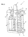
- FIGS. 1 and 2 are perspective views of the subject contact taken from different angles
- FIG. 3 is a perspective view of the contact of FIG. 1 or 2 taken from a left-hand side thereof;
- FIG. 4 is a perspective view of the contact of FIGS. 1 through 3 above showing the front wall portion moved away from the sinuous spring;
- FIG. 5 shows the contact in the flat blank stage after stamping, but prior to forming
- FIG. 6 is a front perspective view of the contact in the deflected state.
- FIG. 7 is a side perspective view of the contact in the deflected state.
- an electrical contact 2 is shown, generally comprising a top contact portion 4 , shown as a plunger contact, with a printed circuit board contact 6 at the opposite end, where the contact portions 4 and 6 are interconnected by way of a spring member 8 .
- the spring member 8 is a sinuous spring, as will be described in greater detail.
- the contact 2 further comprises a rear wall portion 10 , which extends integrally upwardly from the contact portion 6 and further comprises a front wall portion shown at 12 . With reference now to FIG. 4, the contact member 2 is described in greater detail.
- the contact 4 is integrally formed with the sinuous spring 8 and includes a cross bar portion 14 leading into the sinuous spring 8 .
- the sinuous spring 8 is comprised of spring end portions 16 and laterally extending portions 18 .
- the sinuous spring 8 is then interconnected to the printed circuit board contact portion 6 by way of radiused section 20 .
- surface mount contact portion 6 is comprised of a first radiused section 22 , which transitions from the plane of the sinuous spring to a flat mounting portion 24 and then continues into a second radiused section at 26 .
- the radiused sections 22 and 26 define a reverse bend to project the rear wall 10 upwardly in a plane substantially parallel to the plane of the sinuous spring.
- the rear wall 10 includes wing portions 28 formed transversely of the rear wall and defines contact surfaces at 30 positioned adjacent to sinuous spring 8 , but in a noncontacting relation.
- two strap portions 32 extend upwardly from the rear wall portion 10 having inner side edges at 34 , thereby defining opening at 36 .
- the strap portions are bent through a first radiused portion 40 , to define top shoulders 42 (FIG. 2 ), which are continuous through second radiused portions 44 .
- the strap portions 32 are again reversely bent to define front strap portions 46 and thus front wall portion 12 .
- Front wing portions 48 are stamped and formed from the front wall portion 12 and are transversely bent relative to the plane of front wall 12 to define edges at 50 .
- Strap portions 46 continue downwardly and are bent at radiused section 52 , thereby defining stabilizing foot portion at 54 .
- FIG. 3 it should be appreciated that the sinuous spring lies along a plane 60 , whereas the contact portion 4 is skewed at an angle ⁇ , as will be further described herein.
- the contact 2 is shown in the flat blank state, where the contact portion 4 is interconnected to the sinuous spring 8 by way of the cross bar 14 .
- the portion of the flat blank which forms the lower or printed circuit board contact 6 .
- Extending integrally from the printed circuit contact 6 is the rear wall 10 having along the side edges thereof, wing portions 28 .
- Strap portions 32 extend from the rear wall portion 10 , thereby defining the opening at 34 .
- Wing portions 48 are shown in the preformed position, and stabilizing foot 54 is shown prior to forming as well.
- the wing portions 28 , 48 are first formed to lie in a transverse direction to the plane shown.
- the first formation occurs at radiused sections 22 and 26 , which thereby positions edges 30 adjacent to the inner surface of the sinuous spring.
- the front radiused section 44 is thereafter formed, which places the contact 2 in the position shown in FIG. 4 .
- the second radiused section 40 is thereafter formed, which positions the strap portions 32 in a flanking position relative to the contact member 4 , such that the contact member 4 extends through the opening 34 .
- the contact is formed such that there is a slight contact between upper portions 42 and the cross bar member 14 , thereby adding a slight preload to the contact member 4 within the sinuous spring 8 .
- the contact portion 4 lies in a skewed plane relative to plane 60 , as best shown in FIG. 3, where an angle ⁇ lies between the two planes, as best shown in FIG. 3, and described below.
- the contact 2 can be soldered to a printed circuit board, where the surface mount contact portion 6 can be positioned against a corresponding contact pad and soldered in place.
- the counterpart contact (not shown) is placed against contact portion 4 of contact member 2 , and pushed downwardly, the lateral spring portions 18 give way about their end radiused sections 18 to provide spring deformation as shown in FIG. 6 .
- the top portions 42 not only act as the counterpart to define the top extent of the spring location, it also defines the extent to which the contact 4 can be deflected downwardly.
- the contact 6 provides the advantages of the supple spring contact with good electrical characteristics by way of the shortened resistive path.
Landscapes
- Coupling Device And Connection With Printed Circuit (AREA)
Abstract
Description
Claims (22)
Priority Applications (1)
| Application Number | Priority Date | Filing Date | Title |
|---|---|---|---|
| US09/822,134 US6626708B2 (en) | 2001-03-30 | 2001-03-30 | Single piece spring contact |
Applications Claiming Priority (1)
| Application Number | Priority Date | Filing Date | Title |
|---|---|---|---|
| US09/822,134 US6626708B2 (en) | 2001-03-30 | 2001-03-30 | Single piece spring contact |
Publications (2)
| Publication Number | Publication Date |
|---|---|
| US20020142669A1 US20020142669A1 (en) | 2002-10-03 |
| US6626708B2 true US6626708B2 (en) | 2003-09-30 |
Family
ID=25235249
Family Applications (1)
| Application Number | Title | Priority Date | Filing Date |
|---|---|---|---|
| US09/822,134 Expired - Fee Related US6626708B2 (en) | 2001-03-30 | 2001-03-30 | Single piece spring contact |
Country Status (1)
| Country | Link |
|---|---|
| US (1) | US6626708B2 (en) |
Cited By (41)
| Publication number | Priority date | Publication date | Assignee | Title |
|---|---|---|---|---|
| US20050026512A1 (en) * | 2003-08-01 | 2005-02-03 | Jack Seidler | One piece stamped compressible spring pin |
| US20050070170A1 (en) * | 2003-09-30 | 2005-03-31 | Hongbo Zhang | Connector contact having wiping function |
| US20050157043A1 (en) * | 2004-01-21 | 2005-07-21 | Silverbrook Research Pty Ltd | Printed circuit board with spring action |
| US20050184747A1 (en) * | 2004-02-19 | 2005-08-25 | Sanders David L. | Spring plunger probe |
| US20060079102A1 (en) * | 2004-10-13 | 2006-04-13 | The Ludlow Company Lp | Cable terminal with flexible contacts |
| US20060238209A1 (en) * | 2002-05-07 | 2006-10-26 | Microfabrica Inc. | Vertical microprobes for contacting electronic components and method for making such probes |
| US20080111573A1 (en) * | 2003-02-04 | 2008-05-15 | Microfabrica Inc. | Pin-Type Probes for Contacting Electronic Circuits and Methods for Making Such Probes |
| US20080211524A1 (en) * | 2003-02-04 | 2008-09-04 | Microfabrica Inc. | Electrochemically Fabricated Microprobes |
| US20080278187A1 (en) * | 2007-05-07 | 2008-11-13 | Hongfei Yan | Test pin, method of manufacturing same, and system containing same |
| US20090111289A1 (en) * | 2007-10-29 | 2009-04-30 | Ardent Concepts, Inc. | Compliant Electrical Contact and Assembly |
| US20100073021A1 (en) * | 2008-09-23 | 2010-03-25 | Nichepac Technology Inc. | Electrical contact probe |
| US20100118354A1 (en) * | 1999-05-25 | 2010-05-13 | Silverbrook Research Pty Ltd | Sensing Device |
| US20100285698A1 (en) * | 2008-01-02 | 2010-11-11 | Hong-Dae Lee | Probe pin composed in one body and the method of making it |
| US20100291810A1 (en) * | 2009-05-18 | 2010-11-18 | Chi Mei Communication Systems, Inc. | Elastic sheet structure |
| US20120231667A1 (en) * | 2011-03-08 | 2012-09-13 | Fujitsu Component Limited | Interposer and joint terminal |
| US20130035006A1 (en) * | 2011-08-03 | 2013-02-07 | Samsung Electronics Co., Ltd. | Contact terminal |
| US20130035003A1 (en) * | 2010-04-14 | 2013-02-07 | Erich Frank | Electrical plug-in connector element and plug-in connector part comprising a plurality of plug-in connector elements |
| US20130040510A1 (en) * | 2011-08-09 | 2013-02-14 | Shinichi Ishizuka | Connector |
| CN103238078A (en) * | 2010-12-03 | 2013-08-07 | 安达概念公司 | Compliant electrical contact and assembly |
| US8506307B2 (en) | 2010-12-02 | 2013-08-13 | Interconnect Devices, Inc. | Electrical connector with embedded shell layer |
| US20130210253A1 (en) * | 2012-02-10 | 2013-08-15 | Yazaki Corporation | Terminal fitting and bulb socket |
| US20150111400A1 (en) * | 2013-10-18 | 2015-04-23 | Japan Aviation Electronics Industry, Limited | Connector |
| US20170250486A1 (en) * | 2016-02-29 | 2017-08-31 | Enplas Corporation | Contact pin and socket for electrical component |
| CN107243543A (en) * | 2017-06-30 | 2017-10-13 | 昆山杰顺通精密组件有限公司 | The manufacture method of elastic probe |
| CN109075482A (en) * | 2016-06-17 | 2018-12-21 | 阿尔卑斯电气株式会社 | Crimp contactor and manufacturing method thereof |
| US20190148846A1 (en) * | 2016-12-26 | 2019-05-16 | Huawei Technologies Co., Ltd. | Spring and Terminal |
| US10416192B2 (en) | 2003-02-04 | 2019-09-17 | Microfabrica Inc. | Cantilever microprobes for contacting electronic components |
| US11262383B1 (en) | 2018-09-26 | 2022-03-01 | Microfabrica Inc. | Probes having improved mechanical and/or electrical properties for making contact between electronic circuit elements and methods for making |
| US11309652B2 (en) * | 2018-01-16 | 2022-04-19 | Kitagawa Industries Co., Ltd. | Contact for electrically connecting a first member and a second member using spring part |
| US11761982B1 (en) | 2019-12-31 | 2023-09-19 | Microfabrica Inc. | Probes with planar unbiased spring elements for electronic component contact and methods for making such probes |
| US11774467B1 (en) | 2020-09-01 | 2023-10-03 | Microfabrica Inc. | Method of in situ modulation of structural material properties and/or template shape |
| US11802891B1 (en) | 2019-12-31 | 2023-10-31 | Microfabrica Inc. | Compliant pin probes with multiple spring segments and compression spring deflection stabilization structures, methods for making, and methods for using |
| US11973301B2 (en) | 2018-09-26 | 2024-04-30 | Microfabrica Inc. | Probes having improved mechanical and/or electrical properties for making contact between electronic circuit elements and methods for making |
| US20240159795A1 (en) * | 2021-03-31 | 2024-05-16 | Point Engineering Co., Ltd. | Electrically conductive contact pin |
| US12000865B2 (en) | 2019-02-14 | 2024-06-04 | Microfabrica Inc. | Multi-beam vertical probes with independent arms formed of a high conductivity metal for enhancing current carrying capacity and methods for making such probes |
| US12078657B2 (en) | 2019-12-31 | 2024-09-03 | Microfabrica Inc. | Compliant pin probes with extension springs, methods for making, and methods for using |
| US12146898B2 (en) | 2020-10-02 | 2024-11-19 | Microfabrica Inc. | Multi-beam probes with decoupled structural and current carrying beams and methods of making |
| US12181493B2 (en) | 2018-10-26 | 2024-12-31 | Microfabrica Inc. | Compliant probes including dual independently operable probe contact elements including at least one flat extension spring, methods for making, and methods for using |
| US12196781B2 (en) | 2019-12-31 | 2025-01-14 | Microfabrica Inc. | Probes with planar unbiased spring elements for electronic component contact, methods for making such probes, and methods for using such probes |
| US12196782B2 (en) | 2019-12-31 | 2025-01-14 | Microfabrica Inc. | Probes with planar unbiased spring elements for electronic component contact, methods for making such probes, and methods for using such probes |
| US20250035670A1 (en) * | 2021-11-17 | 2025-01-30 | Point Engineering Co., Ltd. | Electrically conductive contact pin and inspection device having same |
Families Citing this family (11)
| Publication number | Priority date | Publication date | Assignee | Title |
|---|---|---|---|---|
| DE60229376D1 (en) * | 2001-05-29 | 2008-11-27 | Tyco Electronics Amp Gmbh | ARRANGEMENT FOR FIXING A SUNSHADE IN A VEHICLE |
| JP4907191B2 (en) * | 2006-02-17 | 2012-03-28 | 日本発條株式会社 | Conductive contact unit |
| DE102008023761B9 (en) * | 2008-05-09 | 2012-11-08 | Feinmetall Gmbh | Electrical contact element for contact contacting of electrical specimens and corresponding contacting arrangement |
| DE102012223443A1 (en) * | 2012-12-17 | 2014-06-18 | Tyco Electronics Amp Gmbh | Spring contact for plug connector, has guiding element, and spring element comprising spring section that is engaged opposite to guiding section such that spring section is guided in direction that is aligned opposite to another direction |
| JP6389595B2 (en) * | 2013-08-27 | 2018-09-12 | 株式会社ティー・ピー・エス | Electrical contact |
| MY192945A (en) * | 2016-02-22 | 2022-09-19 | Jf Microtechnology Sdn Bhd | Spring contact in a testing apparatus for integrated circuits |
| US20170294787A1 (en) * | 2016-04-08 | 2017-10-12 | Makita Corporation | Charger terminal and charger |
| US11768227B1 (en) | 2019-02-22 | 2023-09-26 | Microfabrica Inc. | Multi-layer probes having longitudinal axes and preferential probe bending axes that lie in planes that are nominally parallel to planes of probe layers |
| WO2021154813A1 (en) * | 2020-01-27 | 2021-08-05 | Amphenol Corporation | Electrical connector with high speed mounting interface |
| EP4184723A1 (en) * | 2021-11-17 | 2023-05-24 | KNORR-BREMSE Systeme für Nutzfahrzeuge GmbH | Electric terminal, terminal assembly, connector assembly and method for manufacturing the terminal assembly |
| US12476397B2 (en) * | 2022-04-07 | 2025-11-18 | Semiconductor Components Industries, Llc | Transfer molded power modules and methods of manufacture |
Citations (17)
| Publication number | Priority date | Publication date | Assignee | Title |
|---|---|---|---|---|
| US4773877A (en) | 1986-08-19 | 1988-09-27 | Feinmetall Gmbh | Contactor for an electronic tester |
| US4778404A (en) | 1983-12-27 | 1988-10-18 | Amp Incorporated | Spring terminal |
| US5167512A (en) * | 1991-07-05 | 1992-12-01 | Walkup William B | Multi-chip module connector element and system |
| WO1994011925A1 (en) | 1992-11-11 | 1994-05-26 | Elco Europe Limited | Electrical connector |
| US5362262A (en) | 1992-12-11 | 1994-11-08 | The Whitaker Corporation | Vibration proof electrical receptacle |
| DE4319756A1 (en) | 1993-06-15 | 1994-12-22 | Grote & Hartmann | Electrical plug contact sleeve |
| US5427545A (en) | 1993-02-25 | 1995-06-27 | The Whitaker Corporation | Insulation displacement electrical terminal assembly |
| US5520548A (en) | 1993-06-29 | 1996-05-28 | The Whitaker Corporation | Vibration proof electrical connector housing |
| EP0718919A1 (en) | 1994-12-20 | 1996-06-26 | Connector Systems Technology N.V. | Connector with spring contact member and shorting means |
| EP0718918A1 (en) | 1994-12-20 | 1996-06-26 | Connector Systems Technology N.V. | Connector with spring contact member and shorting means |
| WO1996028865A1 (en) | 1995-03-16 | 1996-09-19 | The Whitaker Corporation | Portable telephone connection system |
| US5611717A (en) | 1994-04-22 | 1997-03-18 | The Whitaker Corporation | Miniature anti-fretting receptacle terminal |
| US5741163A (en) | 1995-07-26 | 1998-04-21 | The Whitaker Corporation | Electrical receptacle terminal |
| US5755599A (en) | 1994-03-17 | 1998-05-26 | The Whitaker Corporation | Electrical contact |
| US5807123A (en) | 1994-10-27 | 1998-09-15 | The Whitaker Corporation | Radio-telephone cradle connector |
| US5865641A (en) | 1994-07-12 | 1999-02-02 | Delaware Capital Formation | Solid spring electrical contacts for electrical connectors and probes |
| US6299458B1 (en) * | 1998-10-27 | 2001-10-09 | Hirose Electric Co., Ltd. | Intermediate electrical connector |
-
2001
- 2001-03-30 US US09/822,134 patent/US6626708B2/en not_active Expired - Fee Related
Patent Citations (17)
| Publication number | Priority date | Publication date | Assignee | Title |
|---|---|---|---|---|
| US4778404A (en) | 1983-12-27 | 1988-10-18 | Amp Incorporated | Spring terminal |
| US4773877A (en) | 1986-08-19 | 1988-09-27 | Feinmetall Gmbh | Contactor for an electronic tester |
| US5167512A (en) * | 1991-07-05 | 1992-12-01 | Walkup William B | Multi-chip module connector element and system |
| WO1994011925A1 (en) | 1992-11-11 | 1994-05-26 | Elco Europe Limited | Electrical connector |
| US5362262A (en) | 1992-12-11 | 1994-11-08 | The Whitaker Corporation | Vibration proof electrical receptacle |
| US5427545A (en) | 1993-02-25 | 1995-06-27 | The Whitaker Corporation | Insulation displacement electrical terminal assembly |
| DE4319756A1 (en) | 1993-06-15 | 1994-12-22 | Grote & Hartmann | Electrical plug contact sleeve |
| US5520548A (en) | 1993-06-29 | 1996-05-28 | The Whitaker Corporation | Vibration proof electrical connector housing |
| US5755599A (en) | 1994-03-17 | 1998-05-26 | The Whitaker Corporation | Electrical contact |
| US5611717A (en) | 1994-04-22 | 1997-03-18 | The Whitaker Corporation | Miniature anti-fretting receptacle terminal |
| US5865641A (en) | 1994-07-12 | 1999-02-02 | Delaware Capital Formation | Solid spring electrical contacts for electrical connectors and probes |
| US5807123A (en) | 1994-10-27 | 1998-09-15 | The Whitaker Corporation | Radio-telephone cradle connector |
| EP0718919A1 (en) | 1994-12-20 | 1996-06-26 | Connector Systems Technology N.V. | Connector with spring contact member and shorting means |
| EP0718918A1 (en) | 1994-12-20 | 1996-06-26 | Connector Systems Technology N.V. | Connector with spring contact member and shorting means |
| WO1996028865A1 (en) | 1995-03-16 | 1996-09-19 | The Whitaker Corporation | Portable telephone connection system |
| US5741163A (en) | 1995-07-26 | 1998-04-21 | The Whitaker Corporation | Electrical receptacle terminal |
| US6299458B1 (en) * | 1998-10-27 | 2001-10-09 | Hirose Electric Co., Ltd. | Intermediate electrical connector |
Cited By (65)
| Publication number | Priority date | Publication date | Assignee | Title |
|---|---|---|---|---|
| US20100118354A1 (en) * | 1999-05-25 | 2010-05-13 | Silverbrook Research Pty Ltd | Sensing Device |
| US20060238209A1 (en) * | 2002-05-07 | 2006-10-26 | Microfabrica Inc. | Vertical microprobes for contacting electronic components and method for making such probes |
| US20100134131A1 (en) * | 2003-02-04 | 2010-06-03 | Microfabrica Inc. | Electrochemically Fabricated Microprobes |
| US10788512B2 (en) | 2003-02-04 | 2020-09-29 | Microfabrica Inc. | Cantilever microprobes for contacting electronic components |
| US10416192B2 (en) | 2003-02-04 | 2019-09-17 | Microfabrica Inc. | Cantilever microprobes for contacting electronic components |
| US20080211524A1 (en) * | 2003-02-04 | 2008-09-04 | Microfabrica Inc. | Electrochemically Fabricated Microprobes |
| US20080111573A1 (en) * | 2003-02-04 | 2008-05-15 | Microfabrica Inc. | Pin-Type Probes for Contacting Electronic Circuits and Methods for Making Such Probes |
| US20050026512A1 (en) * | 2003-08-01 | 2005-02-03 | Jack Seidler | One piece stamped compressible spring pin |
| WO2005013425A1 (en) * | 2003-08-01 | 2005-02-10 | Interplex Nas, Inc. | One-piece stamped compressible spring pin |
| US20050070170A1 (en) * | 2003-09-30 | 2005-03-31 | Hongbo Zhang | Connector contact having wiping function |
| US20060250492A1 (en) * | 2004-01-21 | 2006-11-09 | Silverbrook Research Pty Ltd | Printer having sprung printed circuit board for printhead assembly |
| US7104629B2 (en) * | 2004-01-21 | 2006-09-12 | Silverbrook Research Pty Ltd | Printed circuit board with spring action |
| US7438388B2 (en) | 2004-01-21 | 2008-10-21 | Silverbrook Research Pty Ltd | Printer having sprung printed circuit board for printhead assembly |
| US20090002443A1 (en) * | 2004-01-21 | 2009-01-01 | Silverbrook Research Pty Ltd | Printer assembly with a dimensionally stable support frame |
| US7798605B2 (en) | 2004-01-21 | 2010-09-21 | Silverbrook Research Pty Ltd | Printer assembly with a dimensionally stable support frame |
| US20050157043A1 (en) * | 2004-01-21 | 2005-07-21 | Silverbrook Research Pty Ltd | Printed circuit board with spring action |
| US20050184747A1 (en) * | 2004-02-19 | 2005-08-25 | Sanders David L. | Spring plunger probe |
| US20060079102A1 (en) * | 2004-10-13 | 2006-04-13 | The Ludlow Company Lp | Cable terminal with flexible contacts |
| US20080278187A1 (en) * | 2007-05-07 | 2008-11-13 | Hongfei Yan | Test pin, method of manufacturing same, and system containing same |
| US7521949B2 (en) * | 2007-05-07 | 2009-04-21 | Intel Corporation | Test pin, method of manufacturing same, and system containing same |
| US7556503B2 (en) * | 2007-10-29 | 2009-07-07 | Ardent Concepts, Inc. | Compliant electrical contact and assembly |
| US20090111289A1 (en) * | 2007-10-29 | 2009-04-30 | Ardent Concepts, Inc. | Compliant Electrical Contact and Assembly |
| US20100285698A1 (en) * | 2008-01-02 | 2010-11-11 | Hong-Dae Lee | Probe pin composed in one body and the method of making it |
| US20100073021A1 (en) * | 2008-09-23 | 2010-03-25 | Nichepac Technology Inc. | Electrical contact probe |
| US20100291810A1 (en) * | 2009-05-18 | 2010-11-18 | Chi Mei Communication Systems, Inc. | Elastic sheet structure |
| US8052428B2 (en) * | 2009-05-18 | 2011-11-08 | Chi Mei Communication Systems, Inc. | Elastic sheet structure |
| US20130035003A1 (en) * | 2010-04-14 | 2013-02-07 | Erich Frank | Electrical plug-in connector element and plug-in connector part comprising a plurality of plug-in connector elements |
| US9004955B2 (en) * | 2010-04-14 | 2015-04-14 | Pfisterer Kontaktsyteme GmbH | Electrical plug-in connector element and plug-in connector part comprising a plurality of plug-in connector elements |
| US8506307B2 (en) | 2010-12-02 | 2013-08-13 | Interconnect Devices, Inc. | Electrical connector with embedded shell layer |
| CN103238078A (en) * | 2010-12-03 | 2013-08-07 | 安达概念公司 | Compliant electrical contact and assembly |
| US20120231667A1 (en) * | 2011-03-08 | 2012-09-13 | Fujitsu Component Limited | Interposer and joint terminal |
| US8753130B2 (en) * | 2011-03-08 | 2014-06-17 | Fujitsu Component Limited | Interposer and joint terminal |
| US8668529B2 (en) * | 2011-08-03 | 2014-03-11 | Samsung Electronics Co., Ltd. | Contact terminal |
| US20130035006A1 (en) * | 2011-08-03 | 2013-02-07 | Samsung Electronics Co., Ltd. | Contact terminal |
| US20130040510A1 (en) * | 2011-08-09 | 2013-02-14 | Shinichi Ishizuka | Connector |
| US20130210253A1 (en) * | 2012-02-10 | 2013-08-15 | Yazaki Corporation | Terminal fitting and bulb socket |
| US8961244B2 (en) * | 2012-02-10 | 2015-02-24 | Yazaki Corporation | Terminal fitting and bulb socket |
| US20150111400A1 (en) * | 2013-10-18 | 2015-04-23 | Japan Aviation Electronics Industry, Limited | Connector |
| US9379466B2 (en) * | 2013-10-18 | 2016-06-28 | Japan Aviaton Electronics Industry, Limited | Connector |
| US20170250486A1 (en) * | 2016-02-29 | 2017-08-31 | Enplas Corporation | Contact pin and socket for electrical component |
| US10044127B2 (en) * | 2016-02-29 | 2018-08-07 | Enplas Corporation | Contact pin and socket for electrical component |
| US20190097345A1 (en) * | 2016-06-17 | 2019-03-28 | Alps Electric Co., Ltd. | Spring contact and method of manufacturing same |
| US10446966B2 (en) * | 2016-06-17 | 2019-10-15 | Alps Alpine Co., Ltd. | Spring contact and method of manufacturing same |
| CN109075482A (en) * | 2016-06-17 | 2018-12-21 | 阿尔卑斯电气株式会社 | Crimp contactor and manufacturing method thereof |
| US20190148846A1 (en) * | 2016-12-26 | 2019-05-16 | Huawei Technologies Co., Ltd. | Spring and Terminal |
| US10608351B2 (en) * | 2016-12-26 | 2020-03-31 | Huawei Technologies Co., Ltd. | Spring and terminal |
| CN107243543A (en) * | 2017-06-30 | 2017-10-13 | 昆山杰顺通精密组件有限公司 | The manufacture method of elastic probe |
| US11309652B2 (en) * | 2018-01-16 | 2022-04-19 | Kitagawa Industries Co., Ltd. | Contact for electrically connecting a first member and a second member using spring part |
| US11973301B2 (en) | 2018-09-26 | 2024-04-30 | Microfabrica Inc. | Probes having improved mechanical and/or electrical properties for making contact between electronic circuit elements and methods for making |
| US11262383B1 (en) | 2018-09-26 | 2022-03-01 | Microfabrica Inc. | Probes having improved mechanical and/or electrical properties for making contact between electronic circuit elements and methods for making |
| US11982689B2 (en) | 2018-09-26 | 2024-05-14 | Microfabrica Inc. | Probes having improved mechanical and/or electrical properties for making contact between electronic circuit elements and methods for making |
| US12181493B2 (en) | 2018-10-26 | 2024-12-31 | Microfabrica Inc. | Compliant probes including dual independently operable probe contact elements including at least one flat extension spring, methods for making, and methods for using |
| US12000865B2 (en) | 2019-02-14 | 2024-06-04 | Microfabrica Inc. | Multi-beam vertical probes with independent arms formed of a high conductivity metal for enhancing current carrying capacity and methods for making such probes |
| US11906549B1 (en) | 2019-12-31 | 2024-02-20 | Microfabrica Inc. | Compliant pin probes with flat extension springs, methods for making, and methods for using |
| US11867721B1 (en) | 2019-12-31 | 2024-01-09 | Microfabrica Inc. | Probes with multiple springs, methods for making, and methods for using |
| US11802891B1 (en) | 2019-12-31 | 2023-10-31 | Microfabrica Inc. | Compliant pin probes with multiple spring segments and compression spring deflection stabilization structures, methods for making, and methods for using |
| US12066462B2 (en) | 2019-12-31 | 2024-08-20 | Microfabrica Inc. | Probes with planar unbiased spring elements for electronic component contact and methods for making such probes |
| US12078657B2 (en) | 2019-12-31 | 2024-09-03 | Microfabrica Inc. | Compliant pin probes with extension springs, methods for making, and methods for using |
| US11761982B1 (en) | 2019-12-31 | 2023-09-19 | Microfabrica Inc. | Probes with planar unbiased spring elements for electronic component contact and methods for making such probes |
| US12196781B2 (en) | 2019-12-31 | 2025-01-14 | Microfabrica Inc. | Probes with planar unbiased spring elements for electronic component contact, methods for making such probes, and methods for using such probes |
| US12196782B2 (en) | 2019-12-31 | 2025-01-14 | Microfabrica Inc. | Probes with planar unbiased spring elements for electronic component contact, methods for making such probes, and methods for using such probes |
| US11774467B1 (en) | 2020-09-01 | 2023-10-03 | Microfabrica Inc. | Method of in situ modulation of structural material properties and/or template shape |
| US12146898B2 (en) | 2020-10-02 | 2024-11-19 | Microfabrica Inc. | Multi-beam probes with decoupled structural and current carrying beams and methods of making |
| US20240159795A1 (en) * | 2021-03-31 | 2024-05-16 | Point Engineering Co., Ltd. | Electrically conductive contact pin |
| US20250035670A1 (en) * | 2021-11-17 | 2025-01-30 | Point Engineering Co., Ltd. | Electrically conductive contact pin and inspection device having same |
Also Published As
| Publication number | Publication date |
|---|---|
| US20020142669A1 (en) | 2002-10-03 |
Similar Documents
| Publication | Publication Date | Title |
|---|---|---|
| US6626708B2 (en) | Single piece spring contact | |
| US6783405B1 (en) | Terminal for electric connector for communication apparatus | |
| US8092232B2 (en) | Board-to-board connector | |
| KR100358878B1 (en) | Electrical Terminal | |
| US6231396B1 (en) | Jack connector | |
| JP3551770B2 (en) | Coaxial connector | |
| KR101041656B1 (en) | Contact and Electrical Connectors | |
| US8821198B2 (en) | Surface mounted electrical contact | |
| US7938697B2 (en) | Torsion-style connector | |
| US6855010B1 (en) | Terminal for electric connector for communication apparatus | |
| CN102195153B (en) | Board terminal | |
| US4880401A (en) | Electric female connector piece | |
| US6574855B1 (en) | Method of making a switch-equipped coaxial connector | |
| US20070243772A1 (en) | Exposed-spring female terminal | |
| EP1528638A2 (en) | Card connector | |
| US7040935B2 (en) | Elastic terminal | |
| JP4037259B2 (en) | Electrical connector | |
| US5716230A (en) | Surface engageable electrical connector | |
| US7585194B2 (en) | Conductor pin | |
| US6155844A (en) | Electrical connector for mounting a panel-like device on a printed board | |
| US10707619B2 (en) | Movable connector | |
| US6971928B2 (en) | Contact and connector utilizing the same | |
| EP0883855A1 (en) | Apparatus for the electrical connection of a chip card to a printed circuit board | |
| US7014481B2 (en) | Card connector | |
| US6371811B1 (en) | Vertical-type universal serial bus connector having a low profile on a printed circuit board |
Legal Events
| Date | Code | Title | Description |
|---|---|---|---|
| AS | Assignment |
Owner name: TYCO ELECTRONICS CORPORATION, PENNSYLVANIA Free format text: ASSIGNMENT OF ASSIGNORS INTEREST;ASSIGNOR:PHILLIPS, MICHAEL J.;REEL/FRAME:011664/0871 Effective date: 20010330 |
|
| CC | Certificate of correction | ||
| FPAY | Fee payment |
Year of fee payment: 4 |
|
| FPAY | Fee payment |
Year of fee payment: 8 |
|
| REMI | Maintenance fee reminder mailed | ||
| LAPS | Lapse for failure to pay maintenance fees | ||
| STCH | Information on status: patent discontinuation |
Free format text: PATENT EXPIRED DUE TO NONPAYMENT OF MAINTENANCE FEES UNDER 37 CFR 1.362 |
|
| STCH | Information on status: patent discontinuation |
Free format text: PATENT EXPIRED DUE TO NONPAYMENT OF MAINTENANCE FEES UNDER 37 CFR 1.362 |
|
| FP | Lapsed due to failure to pay maintenance fee |
Effective date: 20150930 |