US6615024B1 - Method and apparatus for determining signatures for calibrating a communication station having an antenna array - Google Patents
Method and apparatus for determining signatures for calibrating a communication station having an antenna array Download PDFInfo
- Publication number
- US6615024B1 US6615024B1 US09/295,434 US29543499A US6615024B1 US 6615024 B1 US6615024 B1 US 6615024B1 US 29543499 A US29543499 A US 29543499A US 6615024 B1 US6615024 B1 US 6615024B1
- Authority
- US
- United States
- Prior art keywords
- downlink
- signals
- transceiver
- calibration
- remote transceiver
- Prior art date
- Legal status (The legal status is an assumption and is not a legal conclusion. Google has not performed a legal analysis and makes no representation as to the accuracy of the status listed.)
- Expired - Lifetime
Links
Images


Classifications
-
- H—ELECTRICITY
- H04—ELECTRIC COMMUNICATION TECHNIQUE
- H04L—TRANSMISSION OF DIGITAL INFORMATION, e.g. TELEGRAPHIC COMMUNICATION
- H04L25/00—Baseband systems
- H04L25/02—Details ; arrangements for supplying electrical power along data transmission lines
- H04L25/03—Shaping networks in transmitter or receiver, e.g. adaptive shaping networks
- H04L25/03006—Arrangements for removing intersymbol interference
- H04L25/03343—Arrangements at the transmitter end
-
- H—ELECTRICITY
- H01—ELECTRIC ELEMENTS
- H01Q—ANTENNAS, i.e. RADIO AERIALS
- H01Q1/00—Details of, or arrangements associated with, antennas
- H01Q1/12—Supports; Mounting means
- H01Q1/22—Supports; Mounting means by structural association with other equipment or articles
- H01Q1/24—Supports; Mounting means by structural association with other equipment or articles with receiving set
- H01Q1/241—Supports; Mounting means by structural association with other equipment or articles with receiving set used in mobile communications, e.g. GSM
- H01Q1/246—Supports; Mounting means by structural association with other equipment or articles with receiving set used in mobile communications, e.g. GSM specially adapted for base stations
-
- H—ELECTRICITY
- H01—ELECTRIC ELEMENTS
- H01Q—ANTENNAS, i.e. RADIO AERIALS
- H01Q3/00—Arrangements for changing or varying the orientation or the shape of the directional pattern of the waves radiated from an antenna or antenna system
- H01Q3/26—Arrangements for changing or varying the orientation or the shape of the directional pattern of the waves radiated from an antenna or antenna system varying the relative phase or relative amplitude of energisation between two or more active radiating elements; varying the distribution of energy across a radiating aperture
- H01Q3/2605—Array of radiating elements provided with a feedback control over the element weights, e.g. adaptive arrays
-
- H—ELECTRICITY
- H01—ELECTRIC ELEMENTS
- H01Q—ANTENNAS, i.e. RADIO AERIALS
- H01Q3/00—Arrangements for changing or varying the orientation or the shape of the directional pattern of the waves radiated from an antenna or antenna system
- H01Q3/26—Arrangements for changing or varying the orientation or the shape of the directional pattern of the waves radiated from an antenna or antenna system varying the relative phase or relative amplitude of energisation between two or more active radiating elements; varying the distribution of energy across a radiating aperture
- H01Q3/267—Phased-array testing or checking devices
-
- H—ELECTRICITY
- H04—ELECTRIC COMMUNICATION TECHNIQUE
- H04B—TRANSMISSION
- H04B17/00—Monitoring; Testing
- H04B17/10—Monitoring; Testing of transmitters
-
- H—ELECTRICITY
- H04—ELECTRIC COMMUNICATION TECHNIQUE
- H04B—TRANSMISSION
- H04B17/00—Monitoring; Testing
- H04B17/10—Monitoring; Testing of transmitters
- H04B17/11—Monitoring; Testing of transmitters for calibration
-
- H—ELECTRICITY
- H04—ELECTRIC COMMUNICATION TECHNIQUE
- H04B—TRANSMISSION
- H04B17/00—Monitoring; Testing
- H04B17/20—Monitoring; Testing of receivers
- H04B17/21—Monitoring; Testing of receivers for calibration; for correcting measurements
-
- H—ELECTRICITY
- H04—ELECTRIC COMMUNICATION TECHNIQUE
- H04B—TRANSMISSION
- H04B7/00—Radio transmission systems, i.e. using radiation field
- H04B7/005—Control of transmission; Equalising
-
- H—ELECTRICITY
- H04—ELECTRIC COMMUNICATION TECHNIQUE
- H04B—TRANSMISSION
- H04B7/00—Radio transmission systems, i.e. using radiation field
- H04B7/02—Diversity systems; Multi-antenna system, i.e. transmission or reception using multiple antennas
- H04B7/04—Diversity systems; Multi-antenna system, i.e. transmission or reception using multiple antennas using two or more spaced independent antennas
- H04B7/06—Diversity systems; Multi-antenna system, i.e. transmission or reception using multiple antennas using two or more spaced independent antennas at the transmitting station
- H04B7/0613—Diversity systems; Multi-antenna system, i.e. transmission or reception using multiple antennas using two or more spaced independent antennas at the transmitting station using simultaneous transmission
- H04B7/0615—Diversity systems; Multi-antenna system, i.e. transmission or reception using multiple antennas using two or more spaced independent antennas at the transmitting station using simultaneous transmission of weighted versions of same signal
- H04B7/0617—Diversity systems; Multi-antenna system, i.e. transmission or reception using multiple antennas using two or more spaced independent antennas at the transmitting station using simultaneous transmission of weighted versions of same signal for beam forming
-
- H—ELECTRICITY
- H04—ELECTRIC COMMUNICATION TECHNIQUE
- H04B—TRANSMISSION
- H04B7/00—Radio transmission systems, i.e. using radiation field
- H04B7/02—Diversity systems; Multi-antenna system, i.e. transmission or reception using multiple antennas
- H04B7/04—Diversity systems; Multi-antenna system, i.e. transmission or reception using multiple antennas using two or more spaced independent antennas
- H04B7/08—Diversity systems; Multi-antenna system, i.e. transmission or reception using multiple antennas using two or more spaced independent antennas at the receiving station
- H04B7/0837—Diversity systems; Multi-antenna system, i.e. transmission or reception using multiple antennas using two or more spaced independent antennas at the receiving station using pre-detection combining
- H04B7/0842—Weighted combining
- H04B7/0848—Joint weighting
-
- H—ELECTRICITY
- H04—ELECTRIC COMMUNICATION TECHNIQUE
- H04B—TRANSMISSION
- H04B17/00—Monitoring; Testing
- H04B17/10—Monitoring; Testing of transmitters
- H04B17/11—Monitoring; Testing of transmitters for calibration
- H04B17/12—Monitoring; Testing of transmitters for calibration of transmit antennas, e.g. of the amplitude or phase
-
- H—ELECTRICITY
- H04—ELECTRIC COMMUNICATION TECHNIQUE
- H04B—TRANSMISSION
- H04B17/00—Monitoring; Testing
- H04B17/10—Monitoring; Testing of transmitters
- H04B17/11—Monitoring; Testing of transmitters for calibration
- H04B17/14—Monitoring; Testing of transmitters for calibration of the whole transmission and reception path, e.g. self-test loop-back
-
- H—ELECTRICITY
- H04—ELECTRIC COMMUNICATION TECHNIQUE
- H04B—TRANSMISSION
- H04B7/00—Radio transmission systems, i.e. using radiation field
- H04B7/02—Diversity systems; Multi-antenna system, i.e. transmission or reception using multiple antennas
- H04B7/04—Diversity systems; Multi-antenna system, i.e. transmission or reception using multiple antennas using two or more spaced independent antennas
- H04B7/08—Diversity systems; Multi-antenna system, i.e. transmission or reception using multiple antennas using two or more spaced independent antennas at the receiving station
- H04B7/0837—Diversity systems; Multi-antenna system, i.e. transmission or reception using multiple antennas using two or more spaced independent antennas at the receiving station using pre-detection combining
- H04B7/0842—Weighted combining
-
- H—ELECTRICITY
- H04—ELECTRIC COMMUNICATION TECHNIQUE
- H04L—TRANSMISSION OF DIGITAL INFORMATION, e.g. TELEGRAPHIC COMMUNICATION
- H04L25/00—Baseband systems
- H04L25/02—Details ; arrangements for supplying electrical power along data transmission lines
- H04L25/03—Shaping networks in transmitter or receiver, e.g. adaptive shaping networks
- H04L25/03006—Arrangements for removing intersymbol interference
- H04L2025/0335—Arrangements for removing intersymbol interference characterised by the type of transmission
- H04L2025/03426—Arrangements for removing intersymbol interference characterised by the type of transmission transmission using multiple-input and multiple-output channels
Definitions
- This invention relates to the field of wireless communication systems, and more specifically, to a method and apparatus for calibrating a communication station that includes an array of antenna elements.
- Antenna arrays may be used in any wireless communication receiver or transmitter or transceiver (herein under “communication station”) that transmits or receives radio frequency signals using an antenna or antennas.
- the use of antenna arrays in such a communication station provides for antenna performance improvements over the use of a single element antenna. These antenna performance improvements include improved directionality, signal to noise ratio, and interference rejection for received signals, and improved directionality, security, and reduced transmit power requirements for transmitted signals.
- Antenna arrays may be used for signal reception only, for signal transmission only, or for both signal reception and transmission.
- a typical application of antenna array communication stations is in a wireless communication system.
- Examples include a cellular communication system consisting of one or more communication stations, generally called base stations, each communicating with its subscriber units, also called remote terminals and handsets.
- the remote terminal may be mobile or in a fixed location, and when fixed, such a system often is called a wireless local loop system.
- the antenna array typically is at the base station. Terminology for the direction of communication comes from conventional satellite communication, with the satellite replaced by the base station. Thus, communication from the remote terminal to the base station is called the uplink, and communication from the base station to the remote terminal is called the downlink.
- the base station antenna array transmits on the downlink direction and receives on the uplink direction.
- Antenna arrays also may be used in wireless communication systems to add spatial division multiple access (SDMA) capability, which is the ability to communicate with several users at a time over the same “conventional” (FDMA, TDMA or CDMA) channel.
- SDMA spatial division multiple access
- FDMA FDMA
- TDMA TDMA
- CDMA Code Division Multiple Access
- adaptive smart antenna processing including spatial processing
- antenna arrays to increase the spectrum efficiency of SDMA and non-SDMA systems. See Co-owned U.S. Pat. No. 5,515,378 for SPATIAL DIVISION MULTIPLE ACCESS WIRELESS COMMUNICATION SYSTEM, U.S. Pat. No. 5,592,490 for SPECTRALLY EFFICIENT HIGH CAPACITY WIRELESS COMMUNICATION SYSTEMS, U.S. Pat. No.
- the downlink signal is processed by adjusting the amplitude and phase of the baseband signals that are transmitted by each of the antennas of the antenna array.
- Such amplitude and phase control can be described by a complex valued weight, the transmit weight, and the weights for all elements of the array by a complex valued vector, the transmit weight vector.
- the receive (and/or transmit) weights include temporal processing, and then are called spatio-temporal parameters for spatio-temporal processing.
- the receive (and/or transmit) weights may be functions of frequency and applied in the frequency domain or, equivalently, functions of time applied as convolution kernels.
- each convolution kernel if for sampled signals, may itself be described by a set of complex numbers, so that the vector of convolution kernels may be re-written as a complex values weight vector, which, for the case of there being M antennas and each kernel having K entries, would be a vector of KM entries.
- the receive spatial signature characterizes how the base station array receives signals from a particular subscriber unit in the absence of any interference or other subscriber units.
- a receive weight vector for a particular user may be determined using different techniques. For example, it may be determined from spatial signatures. It also may be determined from the uplink signals received at the antennas of the array from that remote user using some knowledge about these uplink signals, for example, the type of modulation used.
- the transmit spatial signature of a particular user characterizes how the remote user receives signals from the base station in the absence of any interference.
- the transmit weight vector used to communicate on the downlink with a particular user is determined either from the receive weight vector (see below under “The Need for Calibration”) or from the transmit spatial signature of the particular user and the transmit spatial signatures of the other users in such a way as to maximize the energy to the particular user and minimize the energy to the other users.
- U.S. Pat. No. 5,592,490 for SPECTRALLY EFFICIENT HIGH CAPACITY WIRELESS COMMUNICATION SYSTEMS describes spatial signatures and their uses
- U.S. Pat. No. 5,828,658 for SPECTRALLY EFFICIENT HIGH CAPACITY WIRELESS COMMUNICATION SYSTEMS WITH SPATIO-TEMPORAL PROCESSING describes how to extend this to spatio-temporal processing using spatio-temporal signatures.
- Frequency division duplex (FDD) systems are those in which uplink and downlink communications with a particular remote user occur at the different frequencies.
- Time division duplex (TDD) systems are those in which uplink and downlink communications with a particular remote user occur at the same frequency but in different time slots. In a TDD system, because of the well known principle of reciprocity, it might be expected that determining the transmit weight vector from the receive weight vector is straightforward.
- the received signals that are being processed may be somewhat distorted by the receive electronics (the receive apparatus chains) associated with each of the antenna elements of the antenna array.
- the receive electronics chain includes the antenna element, cables, filters, RF receivers and other components, physical connections, and analog-to-digital converter (“ADC”) if processing is digital.
- ADC analog-to-digital converter
- RF propagation effects that take place on the uplink between the subscriber unit and a particular receiving antenna, such effects including without limitation the path loss, fading and shading effects, multipath, and near-field scattering, and these effects may be different from antenna element to antenna element.
- the receive electronics chain and the RF propagation effects together make up the uplink spatial signature for the remote user.
- a receive weight vector that does not take these receive electronics chain and RF propagation effects into account will be in error, causing less than optimal reception at the base station.
- communication may still be possible.
- a receive weight vector is determined using some knowledge of the characteristics of the received signal, for example, the type of modulation used, such a method already takes into account the uplink receive electronics chain and RF propagation effects.
- each of the signals radiated by an antenna element goes through a different transmit electronics apparatus chain, thus possibly causing different amplitude and phase shifts in the transmitted signals.
- the purpose of calibration is to determine calibration factors for compensating for the different amplitude and phase errors that occur in the signals in the receive chain and uplink RF propagation, and the different amplitude and phase errors that occur in the transmit chain and downlink RF propagation, the calibration factors used in a communication station to determine a transmit weight vector for transmitting to a remote user from the set of signals received from the remote user. It should be added that because the phase and amplitude shifts that occur in the receive and transmit apparatus chains are, in general, frequency dependent, so in general are the calibration factors frequency dependent.
- the uplink and downlink RF propagation effects cancel so that the calibration factors are independent of the location of the subscriber unit.
- each calibration function describes the transfer function correction required to compensate for the gain and phase errors a signal undergoes when passing through the transmit and receive apparatus chains.
- this can be simplified to multiplicative correction, where each calibration function is a calibration factor—a complex valued number that describes the required amplitude and phase correction required for compensation.
- the set of calibration functions defines a calibration vector function with each element a calibration function.
- the set of calibration factors defines a calibration vector with each element a calibration factor.
- Determining the transmit weight vectors from the receive weight vectors for a particular user is more difficult in the case of an FDD system because reciprocity may no longer be assumed.
- single calibration factors that are independent of the location of the remote user may not be possible. In such a case, one needs to be able to determine the uplink and downlink spatial signatures.
- signature estimation is to determine the uplink and downlink spatial signatures which characterize these differences.
- calibration is a special case of signature estimation when either 1) the RF propagation effects cancel so that downlink weights can be determined from uplink signals or weights, or 2) there is some simple functional relationship of the RF propagation effects so that uplink weights can be determined from uplink signals and some parameters of the remote user, for example, the angle of arrival of the uplink signals.
- PCT Patent application publication WO 95/34103 (published Dec. 14, 1995) entitled ANTENNA ARRAY CALIBRATION, Johannisson, et al., inventors, discloses a method and apparatus for calibrating the transmission (and reception) of an antenna array.
- For transmit calibration an input transmit signal is inputted into each antenna element one antenna at a time. After the input transmit signal has passed through a respective power amplifier, the signal transmitted by each antenna element is sampled by a calibration network. The resulting signal is fed into a receiver, and a computation means relates the received signal with the original transmit signal for each antenna element. Correction factors can then be formed for each antenna element.
- the antenna elements may then be adjusted (in amplitude and phase, or in-phase I and quadrature Q components) using the correction factors so as to ensure that each element is properly calibrated during transmission.
- a known input signal is generated and injected using a calibration network (a passive distribution network) into each antenna element of the antenna array.
- the signals pass from the antenna elements through respective low noise amplifiers, and the signals thus received by each antenna element are measured by a beam forming apparatus.
- the beam forming apparatus can then generate correction factors by comparing the injected signal with the measured signals so as to individually calibrate each antenna element.
- the correction can be described as amplitude and phase corrections, or as corrections in in-phase I and quadrature Q components.
- the system separately calibrates forward and return link phased array antennas on a phased array antenna communication station which is on a satellite.
- a separate remote calibration station is used.
- the probe signal is transmitted to an antenna at the calibration system alternatively from one element (a reference element) and an element under test.
- the signals received at the calibration station are compared to determine the corrections.
- a separate communication link also is used to provide communication between the calibration station and the satellite.
- the remote calibration station is used to transmit to all antenna elements of the phased array, but only two elements are alternately sampled to form the calibration carrier.
- the calibration carrier is then downlinked at Ka band to a gateway hub station for computation.
- a local sense antenna at the satellite's communication station is used to sample outputs of the transmit antenna elements.
- separate calibrations are carried out for receive and transmit paths, and extra equipment is needed, either a separate remote calibration station, with an additional link, or a separate sense antenna system.
- additional hardware is required in the form of a separate calibration station or probe antenna.
- special waveforms need to be used for that calibration, rather than ordinary communication waveforms supported by standard air interfaces. This means that the communication station needs additional hardware for forming and transmitting such waveforms, and the calibration station needs special receiving/demodulating hardware, and cannot reuse standard hardware.
- a Wachs-like system adapted for use in a wireless communication system may not be allowed to operate in some countries.
- Calibration factors for each antenna element are determined as a function of the associated transmit electronics chain and receiver electronics chain transfer functions.
- a single calibration factor is determined for any antenna element.
- the single calibration factor is in phase a function of the difference between the transmit apparatus chain transfer function phase and the receiver apparatus chain transfer function phase associated with a particular antenna element.
- the calibration factors so determined are used for determining a set of transmit weights from a set of receive weights.
- the Parish et al. invention enables determining a single set of calibration factors for the base station which enables a downlink set of weights to be determined from an uplink set of weights without requiring some additional apparatus such as a transponder, and calibrates for differences in base station electronics paths
- the Parish et al. method cannot be adapted to estimate spatial signatures to deal with RF propagation path differences which may occur.
- the base station needs to enter a spatial calibration mode for carrying out the calibration experiment, and thus cannot be used for any other purpose during that time.
- the main purpose of the calibration process is to acquire calibration information for the base station. This may involve measuring the gain and phase differences between the uplink and downlink channels. Accuracy and high precision are of great importance during this procedure. If the calibration information is not accurate, then the beam pattern on the downlink will be highly distorted. As a consequence, less energy will be radiated toward the target user, and an excess amount of interference will be radiated toward co-channel users. This will have a negative effect on the downlink signal quality and on the downlink range. Ultimately, a bad calibration strategy may significantly reduce the capacity of the wireless network.
- One desirable feature of a calibration method is that only a base station and a subscriber unit are needed for calibration with no further equipment such as signal generators, transponders, calibration stations, additional antennas, probes, or other equipment, being required.
- Such a system ideally should be able to calibrate for differences in both the receive and transmit electronics.
- Such systems also should use ordinary communication waveforms substantially conforming to the particular air interface standard of the wireless communication system in which they operate. This enables reusing standard hardware, and also ensures non-violation of standards and maintaining compatibility with any future modifications with standards.
- channel structure is a frequency slot in the case of FDMA, a time and frequency slot in the case of TDMA, and a code channel in the case of CDMA
- modulation is the particular modulation scheme specified in the standard.
- Another desirable feature is that the method can be used for signature estimation in order to also account for differences in the RF paths.
- Another desirable feature of a calibration method is ease of use and the ability to carry out the calibration rapidly and frequently, even for example, as frequently as several times a minute. This ultimately increases the downlink processing accuracy which has a profound effect on signal quality, capacity, coverage, and possibly other parameters.
- Another desirable feature of a calibration method is that each and every subscriber unit supports calibration.
- Another desirable feature for a calibration system is the ability to carry out some or all of the processing of received data for calibration within the subscriber unit, thus not requiring the subscriber unit to send the received data back to the base station and not requiring the base station to carry out all of the processing.
- the computational burden of the base station thus may be significantly reduced by “distributing” the load across intelligent subscriber units. This feature is particularly desirable, for example, for base stations that service many subscriber units, or that calibrate before each call or even several times during each call.
- Another desirable feature is the ability to initiate calibration on any available conventional channel on the base station, for example, any carrier and any time slot of a FDMA/TDMA system. This further enhances flexibility since one can choose any timeslot and any carrier which is available for use at the moment.
- Another desirable characteristic for a calibration method is the ability to calibrate a base station without having to take the base station off-line for calibration, thus enabling base station calibration to be performed while the base station services hundreds of calls, for example, in a FDMA/TDMA/SDMA system on other carriers (frequency slots)/timeslots/spatial channels. This feature is especially important for wideband base stations that service many conventional channels (e.g., carriers for an FDMA/TDMA system) at the same time.
- Another desirable characteristic for a calibration method is the ability carry out rapid calibration even several times during an existing call.
- Another desirable characteristic for a calibration method is the ability to carry out calibration in a seamless manner during an ongoing call so that a base station may be able to continuously calibrate itself during some calls.
- Another desirable characteristic for a calibration method is the ability to carry out calibration with several remote transceivers by combining measurements, each of which may be able to “see” only a subset of a communication station's antenna array, or each of which may face a different interference environment.
- Another desirable characteristic for a calibration method is the ability to determine whether calibration is accurate, for example by performing statistical measurements, together with the ability to feed back such information to the communication station to determine, for example, if the combining from several remote stations may be necessary.
- Another desirable feature is high accuracy, with immunity to frequency offset, timing misalignment, I/Q mismatch, and phase noise that typically might occur in communication with inexpensive subscriber units.
- a calibration method and apparatus that include all or most of the above characteristics.
- a simple calibration technique that only uses existing base station electronics and does not require special calibration hardware.
- a method that enables one to determine transmit weight vectors from receive weight vectors, including calibrating for the receive electronics and transmit electronics, the calibration obtained using simple techniques that use existing base station and subscriber unit electronics and do not require special calibration hardware.
- An feature of the present invention is enabling calibrating a communication station having an antenna array for differences in electronics paths, the calibration using only the communication station and a subscriber unit.
- Another feature of the invention is providing calibration that enables using a calibrated transmit weight vector, the transmit weight vector essentially determined from a receive weight vector, the calibration taking into account differences in electronics paths.
- Another feature of the invention is determining spatial signatures that enable using a calibrated transmit weight vector, the transmit weight vector essentially determined from a receive weight vector, the calibrating taking into account differences in electronics paths and RF propagation paths.
- Another feature of the invention is enabling determining the uplink spatial signature of a subscriber unit communicating with a communication station, the determining using only the communication station and the subscriber unit.
- Another feature of the invention is enabling determining the downlink spatial signature of a subscriber unit communicating with a communication station, the determining using only the communication station and the subscriber unit.
- Still another feature of the invention is calibrating a communication station having an antenna array that the calibrating easy and without taking the communication station off the air for those conventional channels not currently being calibrated.
- Still another feature of the invention is calibrating a communication station having an antenna array, the calibrating able to be carried out partially or in total at a subscriber unit.
- Still another feature of the invention is calibrating a communication station, the calibrating method providing high accuracy, with immunity to frequency offset, timing misalignment, I/Q mismatch, and phase noise that typically might occur in communicating with inexpensive subscriber units.
- Another feature of the invention is providing a calibration method and apparatus that can be readily implemented in a radio frequency system and that make it practical to perform frequent and routine system calibration, the calibration enabling the use of a calibrated transmit weight vector, the transmit weight vector essentially determined from a receive weight vector, the calibration including correcting for differences in electronic paths and for differences in RF propagation effects.
- Yet another feature is enabling rapid calibration even several times during an existing call.
- Yet another feature is enabling carrying out calibration in a seamless manner during an ongoing call so that a communication station may be able to continuously calibrate itself during a particular call.
- Yet another feature is the ability to carry out calibration with several remote is transceivers by combining measurements, each of which may be able to “see” only a subset of a communication station's antenna array, or each of which may face a different interference environment.
- Yet another feature is providing the ability to determine whether calibration is accurate, for example by performing statistical measurements, together with the ability to feedback such information to the communication station to determine, for example, if the combining from several remote stations may be necessary.
- FIG. 1 shows the uplink and downlink signal flow on the base station
- FIG. 2 shows the decomposition of the uplink and downlink channels into “propagation” and “electronic” factors
- FIG. 3 illustrates the frame structure of a typical TDD system
- FIG. 4 shows the receive signal processor and the uplink weight computation
- FIG. 5 illustrates the symmetry between the uplink and downlink signal paths
- FIG. 6 shows the internal structure of the transmit weight generator
- FIG. 7 shows the protocol sequence during calibration
- FIG. 8 illustrates the decomposition of a 6-element circular array into 2-element subarrays
- FIG. 9 illustrates the uplink signature estimation at the base station
- FIG. 10 shows the downlink signature estimation at the subscriber unit
- FIG. 11 shows a flowchart of one embodiment of a method for carrying out downlink signature determination with calibration bursts interspersed with normal TCH bursts;
- FIG. 12 shows the architecture of a typical subscriber unit in which aspects of the present invention may be implemented
- FIG. 13 shows the results of testing a two antenna element implementation of the method for downlink signature estimation
- FIG. 14 shows the results of testing an implementation of the method for downlink signature estimation using a single transmitter and antenna element
- FIG. 15 shows the results of testing an implementation of the method for downlink signature estimation using a single transmitter and antenna element, but with a different set of frequencies than used to obtain the results of FIG. 14 .
- the first one or two digits in a reference numeral indicate on which figure that reference numeral is first introduced.
- Reference numerals between 100 and 199 are first introduced in FIG. 1, those between 200 and 299 are first introduced in FIG. 2, and so forth.
- reference numeral 111 is first introduced in FIG. 1
- 909 is first introduced in FIG. 9
- 1009 is first introduced in FIG. 10
- 1211 is first introduced in FIG. 12 .
- the invention preferably is implemented in wireless cellular communication systems which include a base station (i.e., a transceiver, a communications station) with a multiple antenna array that uses smart antenna techniques for uplink or downlink communication or both.
- a base station i.e., a transceiver, a communications station
- the preferred implementation is in a system that operates using the Personal Handyphone (PHS) air interface communication protocol.
- PHS Personal Handyphone
- Two implementations are one in which the subscriber units are fixed in location, and the other in which subscriber units may be mobile.
- PHS Personal Handyphone
- Two implementations are one in which the subscriber units are fixed in location, and the other in which subscriber units may be mobile.
- Above-mentioned and incorporated-herein-by-reference co-owned U.S. patent application Ser. No. 08/729,390 describes the hardware of a base station of a mobile system in detail, the base station preferably having four antenna elements.
- WLL wireless local loop
- a WLL base station into which some aspects of the present invention are incorporated is described in U.S. patent application Ser. No. 09/020,049 for POWER CONTROL WITH SIGNAL QUALITY ESTIMATION FOR SMART ANTENNA COMMUNICATION SYSTEMS, incorporated-herein-by-reference, while the subscriber unit for use in such a WLL system is described in U.S. patent application Ser. No.
- the invention also is applicable to peer to peer communication from one radio to another.
- the communication station in this context may be any radio transceiver equipped with an antenna array
- the subscriber unit may be any other radio transceiver remote to the array-equipped transceiver and able to communicate with the array-equipped transceiver using some modulation scheme.
- the preferred embodiment describes a base station that has a single array for both uplink (receive) processing and downlink (transmit) processing, with means for adaptive smart antenna processing on the uplink and the downlink
- the invention also is applicable to a base station that has an array only for transmit processing, and for a base station that uses a separate antenna array for uplink processing and for downlink processing.
- the calibration factor is the downlink signature since all received signals pass through the same receive electronics chain.
- the “number” of antenna is clearly the number of “active” antennas, that is, the number of antenna used for communication.
- the calibration is intended in the embodiments described herein for use in adaptive smart antenna processing, the calibration may be for any other purpose, so that the antenna-array-equipped transceiver need not even include means for adaptive smart antenna processing.
- FIG. 1 depicts the uplink and downlink signal flow through a typical base station (BS) on which the present invention may be embodied.
- Base station 101 includes an array of antenna elements 105 .
- the base station communicates with one or more subscriber units such as subscriber unit 141 and subscriber unit 143 .
- the base station has a single array of antenna elements that are used for both receive and transmit, so that a receive/transmit unit 107 is used.
- For frequency domain duplexing unit 107 is a frequency duplexer and for time domain duplexing (TDD), such as used in the preferred embodiment, unit 107 is a switch.
- TDD time domain duplexing
- receive RF electronics 109 converts the RF signals to baseband signals 110 .
- receive RF electronics unit 109 includes analog RF components, including analog downconversion, analog to digital converters, and digital downconverter components to produce digital baseband antenna signals 110 , and these baseband received antenna signals are processed by receive signal processor 111 to generate a received signal from a particular subscriber unit, for example subscriber unit 141 .
- the receive signal processor includes determining a weighted sum of the complex valued (in phase I and quadrature Q) antenna signals in an optimal manner where the weighting is in amplitude and phase, and where optimal means that the desired signal components are enhanced by a maximum amount and the non-desired components are suppressed by a maximum amount.
- the complex valued receive weights are computed by locking onto a known training sequence, or by using some decision-directed technique, or “blindly” by using some other special structure in the signal.
- it is not essential to know the phase and amplitude relations of the receive electronics in order to perform the computation of the uplink (i.e. receive) weights. See below and in above-referenced co-owned U.S. patent application Ser. No. 08/729,390 filed Oct. 11, 1996 for more details on how these weights are computed.
- FIG. 1 shows the output of the receiver part of the base station as being voice or data 113 with signals which are directed to the Network Interface Unit (NIU).
- receive signal processor 111 also includes all the demodulation function.
- a transmit signal processor 123 includes distributing complex valued weighted copies 124 of the modulated baseband signal (the weighting according to a set of complex valued transmit weights), and the weighted transmit antenna signals are fed to transmit RF electronics unit 125 to generate a set of RF transmit signals 127 , one signal aimed at each antenna element of antenna array 105 . These RF antenna signals are fed to the corresponding antenna array element through TX/RX switch 107 which is set in the transmit position.
- the transmit weights are chosen so that the antenna array radiates most of the energy towards a particular subscriber unit (“beam-forming”) and it transmits minimal energy toward co-channel users (“null-placing”).
- the set of transmit weights 118 is computed directly from the set of receive weights 115 generated by receive signal processor 111 , and the computation is carried out by transmit weight generator 117 in real time.
- the transmit weight generator 117 must take into account the gain and phase differences between the uplink and downlink propagation channels where the channels include both the air path from and to a subscriber unit and the variation among the different signal parts within the receive RF electronics and also within the transmit RF electronics.
- this information is stored in calibration storage unit 131 in the form of a calibration vector 133 as will be described below. Determining this calibration information is the main goal of the present invention.
- the number of elements in the base station antenna array 105 shall be denoted by M.
- M the number of elements in the base station antenna array 105
- M the number of elements in the base station antenna array 105
- M signal paths one from each of the M inputs of transmit signal processor 123 to the subscriber unit.
- Each of these signal paths is described herein by a complex valued number that characterizes the phase and amplitude distortion of a baseband signal.
- the uplink and downlink channels thus are mathematically described by M-dimensional complex valued vectors denoted a rx and a tx , respectively, where M is the number of elements in the base-station antenna array 105 , and where each element in the vector represents the path associated with one of the antenna elements in array 105 .
- M is the number of elements in the base-station antenna array 105
- each element in the vector represents the path associated with one of the antenna elements in array 105 .
- the vectors a rx and a tx may be recognized as the (un-normalized) uplink spatial signature and downlink spatial signature, respectively, for the subscriber unit for this base station.
- the uplink and downlink signatures, and the uplink and downlink weights will all be described in baseband. It would be clear to those of ordinary skill in the art that the adaptive smart antenna processing, including any weighting in amplitude and phase, may alternatively be carried out in some other band, for example, in intermediate frequency or in the passband. In such a case, the signature and all its components similarly would be defined in that frequency band.
- the main goal of the invention is to calibrate the base station. Assuming identical RF propagation on the uplink and downlink, a single subscriber unit can be used together with its base station to carry out the calibration. It also will be apparent that the method enables the separate determination of the uplink and downlink signatures for any subscriber unit. The ease with which such data can be obtained enables one to obtain complete signature information for any (and even every) active subscriber unit. Therefore, in addition to calibrating the base station by running a simple calibration experiment with one of the subscriber units, the method enables subscriber dependent uplink and downlink signatures to be determined for any subscriber unit, these signatures including the effects of the electronic signal paths in the base station hardware and any differences between the uplink and downlink electronic signal paths for the subscriber unit.
- the single calibration vector is the average calibration vector.
- it is the weighted average calibration vector, the weighting given to the estimate made using a particular subscriber unit dependent on a measure of the quality of the signal received by that subscriber unit, so that estimates from subscriber units having better quality signals are weighed more in the weighted average.
- N the number of samples of a burst to use for the estimate.
- the sampled modulus information is first extracted by forming the sum of the squares of the in phase and quadrature received signals.
- the mean power and mean squared power are then determined using averages over the number of samples for the expectation operation.
- This preferred method of signal quality estimation is insensitive to frequency offset, and so is a particularly attractive method for use with the CM method which also is insensitive to frequency offsets.
- the single calibration vector estimate may be obtained using some other function of the several determinations of calibration vectors, for example, taking from each calibration vector only the good quality estimates of the element, and then combining all the subsets to obtain one high quality calibration vector.
- phase and magnitude distortions that occur in the various signal paths are described by the amplitude and phase, respectively, of a single complex valued number, so that a calibration for a one-to-M or M-to-one system is described by a M-dimensional complex valued vector.
- a different complex number may be required to describe the phase and magnitude distortions for each carrier (each frequency band).
- the electronics may be adequately described by a simple phase and amplitude factor
- the RF propagation part within each frequency band of a carrier is not adequately described by a complex number, but is adequately described by a transfer function.
- the transfer functions cancel out when used for calibration, so that a complex number adequately describes the calibration for one antenna's uplink-downlink signal path, and a complex valued M-dimensional calibration vector is adequate.
- FIG. 2 shows how the uplink and downlink channel descriptions are further mathematically decomposed into the product of “propagation” and “electronic” factors in the following manner.
- a complex valued number that describes the phase and amplitude distortion that occurs in a baseband signal due to the RF propagation effects on the uplink and on the downlink.
- Such propagation effects include without limitation path loss, fading and shadowing effects, multipath, and near-field scattering.
- the M such numbers can be combined as M-dimensional complex valued vectors.
- g rx and g tx as these vectors for the uplink and downlink, respectively.
- g rx and g tx are called the propagation factors herein. In a typical low-mobility environment the propagation factors remain constant over several frames (i.e., tens to hundreds of milliseconds).
- phase and amplitude distortion that occurs in a baseband signal due to the receive electronics between an element of the antenna array 105 and the corresponding output terminal of receive signal processor 111
- another complex valued number that describes the phase and amplitude distortion that occurs in a baseband signal in the transmit electronics chain between an input terminal of transmit signal processor 123 and the corresponding element of the antenna array 105
- These electronics chain phase and amplitude distortions include those that occur due to cable losses, imperfect physical connections, variations in the gains of the various active receive or transmit RF electronics, and group delays in the particular components that are included in the RF electronics, for example surface acoustic wave (SAW) filters and other components.
- SAW surface acoustic wave
- the electronic factors remain constant over an extended period of time (minutes, hours or days).
- M electronics based factors for each of the transmit and receive electronics chains. For each direction, these factors can be combined as an M-dimensional complex valued vector. Define receive electronic factor vector e rx as the vector of distortions of the M receive electronics chains, and transmit electronics factor vector e tx as the set of distortions for the M transmit electronics chains.
- the uplink propagation factors vector g rx is shown as 211 and the uplink electronic factors vector e rx is shown as 215
- the downlink electronic factors vector e tx is shown as 217
- the downlink propagation factors vector g tx is shown as 219 .
- ⁇ circle around ( ⁇ ) ⁇ denotes the elementwise product (i.e., the Hadamard product).
- the preferred embodiment system is a frequency division multiple access/time division multiple access (FDMA/TDMA) system in which each conventional channel is a time slot in a frequency channel (a frequency channel is referred to as a “carrier” herein for FDMA/TDMA systems).
- time is divided into frames of timeslots and such a frame is shown as 301 in FIG. 3 .
- Frame 301 of the preferred embodiment includes eight timeslots.
- there are four receive timeslots labeled 0 through 3 (items 305 , 307 , 309 , and 311 ) followed by four transmit timeslots labeled 0 through 3 (items 315 , 317 , 319 , and 321 ) in FIG. 3 .
- the uplink and downlink factors are measured over consecutive receive and transmit slots that are separated by a relatively short time interval. Therefore, by the principle of reciprocity, it is reasonable to assume that the uplink and downlink propagation factors are identical:
- the relation between the uplink and downlink propagation factors may be more complicated, and can still be determined.
- the uplink weights are computed at base station 101 by receive signal processor 111 .
- the uplink weights are summarized by a complex valued M-dimensional complex valued receive weight vector (also called uplink weight vector) 115 denoted by w rx herein, each element of which describes the weighing in amplitude and phase of the baseband received signals.
- the result of applying the weighting generates a baseband signal from the particular subscriber unit.
- the received signals 106 from the antenna elements are digitized and converted to baseband by receive RF electronics unit 109 .
- FIG. 4 shows the preferred embodiment (by programming) of receive signal processing unit 111 , including receive (uplink) weights computation.
- Receive signal processor 111 first performs pass-band filtering, and compensates for frequency offset, timing offset, I/Q mismatch, and other possible distortions. These operations are commonly labeled as “preprocessing,” and are carried out in the preprocessor shown as 403 in FIG. 4 .
- the transmitted symbol sequence 412 is estimated from the set of preprocessed received signals 405 by using a suitable spatial processing and demodulation technique.
- a suitable spatial processing and demodulation technique Referring to FIG. 4, an estimate of the signal from the particular desired subscriber unit is determined by spatial processor 407 by weighting in amplitude and phase by a set of receive weights described by a receive (uplink) weight vector 115 .
- the invention also covers replacing spatial processor 407 with a spatio-temporal processor which includes time equalization.
- spatio-temporal processing the weighting is replaced by a convolution operation in the time domain, or equivalently, multiplication in the frequency domain.
- the convolution usually is finite and on sampled data, and so is equivalent to combining the spatial processing with time equalization using a time-domain equalizer with a finite number of equalizer taps. That is, each of the weights in the weight vector is replaced by a finite number of values. If the length of each convolving function is K, then rather than determining a complex valued M-weight vector w rx , one determines a complex valued M by K matrix W rx .
- a spatial weight determining method can easily be modified for spatio-temporal processing according to a weight matrix by re-expressing the problem in terms of matrices and vectors of different sizes.
- M the number of antenna elements
- N the number of samples.
- K the number of time equalizer taps per antenna element.
- a set of received signal samples can be written as a matrix of row vectors, each row vector representing the single samples from a single antenna. All the signal samples can then be represented by an (M by N) received signal matrix.
- each row vector of N samples of the (M by N) received signal matrix can be rewritten as K rows of shifted versions of the first row to produce a received signal matrix of size (MK by N), which when pre-multiplied by the Hermitian transpose (i.e., complex conjugate transpose) of a weight vector of size (MK by 1) produces an estimated received signal row vector of N samples.
- the spatio-temporal problem has thus been re-expressed as a weight vector determining problem.
- the weight vector is a “long” weight vector of size (MK by 1). Rearranging terms in the “long” weight vector provides the required (M by K) weight matrix. Therefore, while the description herein is in terms of weights and spatial processing, the scope is intended to include spatio-temporal processing.
- an estimate of the uplink weight vector 115 is used, for example the value from the previous frame.
- the signal estimate 408 is then demodulated by demodulator and reference signal generator 411 to generate the estimate of the transmitted symbol sequence 412 which then is further processed by higher level processing unit 413 to generate the voice or data signal 113 that is sent to the Network Interface Unit (not shown).
- demodulation and reference signal generator 411 also produces a reference signal 410 which is a modulated signal that is modulated by the estimated symbols and that has a correct signal structure according to the particular modulation protocol used.
- Weight vector generator 409 implements an optimization method that determines the weight vector that minimizes an objective function of weight vectors, the objective function including a measure of the deviation of the signal generated through a signal copy spatial processing operation using the weight vector to the reference signal 410 .
- the objective function also includes a term to limit the magnitude of the weight vector. The next estimate of the weight vector obtained from weight vector generator 409 can then be used by signal copy operation 407 and also may be used by transmit weight generator 117 .
- the downlink weights 118 may be expressed as an M-dimensional complex valued vector of weights w tx (called the transmit weight vector, also the downlink weight vector). In the preferred embodiment, the downlink weights are computed directly from the uplink weights.
- the symmetry of the uplink and downlink signal paths is used. This symmetry, illustrated in FIGS. 5A (uplink) and 5 B (downlink), may be expressed as follows:
- the impulse response of the scalar “channel” (in baseband) between the modulated baseband signal (shown as 503 ) transmitted by the subscriber unit and the post-spatial processing (i.e., demultiplexed) signal is substantially the same as the opposite direction impulse response from the pre-spatial processing scalar baseband signal 507 transmitted from the base station to the received baseband signal 509 at the subscriber unit.
- this symmetry may be stated as the uplink and downlink weight vectors substantially satisfying the equation
- the beam pattern of the antenna array on the uplink and the downlink should be substantially identical.
- ⁇ circle around ( ⁇ ) ⁇ denotes the elementwise product (i.e., the Hadamard product). Note that in general the beam pattern of the antenna array depends on the weight vectors, as well as on the transfer functions of the RF electronics.
- Eq. (3) has many solutions for w tx while Eq. (4) has only one solution:
- the internal structure of the transmit weight generator 117 is depicted in FIG. 6 .
- the corresponding element of calibration vector 133 is multiplied by the corresponding element of the receive weight vector 115 using elementwise multiplication process 603 .
- the main purpose of the calibration process is to determine calibration vector 133 for a base station and one of its subscriber units which supports the calibration procedure. No additional calibration equipment such as a transponder, signal generator, or measuring network is needed.
- the calibration process consists of the following steps:
- step 4 of computing the calibration function from intermediate quantities related to the uplink and downlink signatures.
- the computation of the calibration function from such intermediate quantities is equivalent to computing the calibration function from uplink and downlink signatures.
- each subscriber unit is able to support the calibration method. Nevertheless, to maximize the signal to noise ratio, it is generally recommended to choose a subscriber unit that is close to the base station. Calibration calls can be initiated on any carrier and any time slot while the base station is servicing standard traffic channel (TCH) calls on other carriers and time slots.
- TCH traffic channel
- the scope clearly includes the base station communicating with a special purpose transceiver that performs the functions described herein, while not necessarily performing any other functions, for example the typical functions a typical subscriber unit performs. For example, one can use a subset of the hardware and software included in a subscriber unit to carry out the calibration.
- burst and used terms such as traffic bursts, calibration bursts, etc.
- the invention certainly is not limited to burst-by-burst systems.
- the general equivalent term to “burst” applicable to both burst-by-burst and non burst-by-burst systems used herein is “waveform”, and therefore a “calibration waveforms” is a calibration burst for a busts-by-burst system, a “traffic waveforms” is a traffic (or TCH) burst for a busts-by-burst system, and so forth.
- FIG. 7 shows a typical protocol which includes a calibration call according to aspects of this invention. Different protocols may be designed for other implementations.
- the sequence order is from top to bottom.
- the direction of arrows shows the direction of communication.
- the protocol starts with a standard call-setup procedure 703 which includes a paging call 711 from the base station to the subscriber unit, a link channel request 713 from the subscriber unit to the base station, resulting in link channel assignment sent to the subscriber in step 715 .
- Synchronization (“SYNCH”) bursts are then sent on the uplink ( 717 ) then on the downlink ( 719 ).
- SYNCH Synchronization
- the subscriber unit transmits a first uplink calibration burst or bursts ( 723 ) so that the base station can estimate the uplink channel.
- the base station transmits a first downlink calibration burst (or bursts) so that the subscriber unit can estimate the downlink channel.
- the calibration bursts are calibration waveforms that conform to the particular air interface standard, in this case, the PHS standard.
- an air interface standard we mean conforming to the channel structure and modulation of an air interface, where “channel structure” is a frequency slot in the case of FDMA, a time and frequency slot in the case of TDMA, or a code channel in the case of CDMA, and “modulation” is, for example, ⁇ /4-DQPSK in the case of PHS, or GMSK in the case of GSM, and so forth.
- the calibration waveform consists of a sum of two or more waveforms each conforming to the PHS air interface standard. As such sums occur naturally in a multiuser communication system with frequency reuse, a sum of waveforms conforming to an air interface standard is also considered to conform to an air interface standard for the purpose of this description.
- one or more additional uplink calibration bursts and one or more additional downlink calibration bursts may needed, each for each additional subarray, and these additional steps are shown as dotted lines 727 and 729 , respectively in FIG. 7 . Note that while only one downlink and one uplink additional step is shown dotted, it is to be understood that this represents as many additional bursts as there are additional subarrays to be calibrated.
- the antennas are calibrated pairwise with each antenna calibrated with respect to a fixed reference antenna.
- the M-element antenna array is viewed as a collection of 2-element subarrays and there are M ⁇ 1 bursts used to calibrate in each direction (steps 727 and 729 each carried out M ⁇ 2 times).
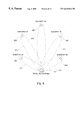
- FIG. 8 s hows a circular arrangement of 6 antennas 801 , 802 , 803 , 805 , 807 , and 809 , with antenna 801 arbitrarily chosen as the fixed reference antenna.
- the subarrays are shown as the antennas within the dotted line areas.
- the five subarrays are: subarray # 1 ( 811 ) of antennas 801 and 802 , subarray # 2 ( 813 ) of antennas 801 and 803 , subarray # 3 ( 815 ) of antennas 801 and 805 , subarray # 4 ( 817 ) of antennas 801 and 807 , and subarray # 5 ( 819 ) of antennas 801 and 809 .
- the subscriber unit has some intelligent signal processing capabilities which allow it to analyze the downlink calibration burst or bursts. In general, some of the downlink channel estimation can then be carried out by the remote subscriber unit, this part of the signature estimation determining partial results, called “downlink signature related signals” herein. In the preferred embodiment, the subscriber unit has sufficient processing power to completely compute the downlink channel estimate, and in this case, the downlink signature related signals are the downlink channel estimate components. These results (whether complete or partial estimates—in general, downlink signature related signals) are sent back to the base station by using some standard messaging protocol, including without limitation SACCH, FACCH, TCH payload as described in the PHS protocol. The PHS protocols are incorporated herein by reference.
- the PHS standard is described, for example, in the Association of Radio Industries and Businesses (ARIB, Japan) Preliminary Standard, Version 2, RCR STD-28 and variations are described in Technical Standards of the PHS Memorandum of Understanding Group (PHS MoU—see http://www.phsmou.or.jp).
- This sending is shown as step 731 for the first downlink calibration burst and as dotted line 733 for those implementations that use additional bursts, for example for the remaining subarrays.
- Other relevant information e.g., signal quality estimates or the raw I/Q samples
- the base station computes the calibration vector and terminates the calibration call.
- the call termination 709 preferably includes a disconnect command 735 from the base station followed by a release message 737 from the subscriber unit.
- uplink signature estimation occurs at an active subscriber unit in the vicinity of the base station. After the service channel is established, the subscriber unit transmits an uplink calibration burst towards the base station. In our particular implementation, the uplink calibration bursts are idle (no-payload) TCH bursts. In alternate embodiments, other sequences can be used, and how to modify the method to use other sequences would be clear to one of ordinary skill in the art.
- downlink signature estimation is carried out first. The downlink signature related signals computed at the subscriber unit, which preferably are the signature estimates, are then transmitted to the base station. These signals are then used to estimate the uplink signature.
- FIG. 9 describes the elements for determining the uplink signature a rx .
- subscriber unit e.g., unit 141
- subscriber unit includes an uplink calibration burst synthesizer 907 implemented as a set of programming instructions on a signal processor.
- Synthesizer 907 includes a memory (part of the already present signal processor memory), and generates the first calibration burst (in step 723 ) or the second calibration burst (in step 727 ).
- the burst is transmitted from the subscriber unit antenna 911 using the subscriber unit's transmit RF electronics 909 .
- the architecture of the preferred embodiment subscriber unit is described in above referenced U.S. patent application Ser. No. 08/907,594 and in FIG. 12 . Referring to FIG.
- time duplexer 1203 is in the transmit position during transmission and connects the output of transmit RF electronics 909 to antenna 911 .
- Normal traffic burst signals are obtained from telephony interface unit 1213 via a vocoder DSP 1209 .
- the complex valued (I, Q) samples are formed in a DSP device (TX DSP 1211 ) which is connected to a memory 1207 shared with another DSP device, the RX DSP 1205 used for signal reception.
- TX DSP 1211 is programmed to carry out the function of uplink calibration burst synthesizer 907 in addition to its normal transmit signal processing functions.
- the uplink calibration bursts are received by the base station antenna array 105 and converted to the baseband signals 110 by the receive RF electronics 109 , as shown in FIG. 9 .
- the signals from the antenna elements are then processed by the receive signal processor 111 which is made up of one or more digital signal processing devices (DSPs) programmed to carry out the functions of the elements 403 , 921 , and 931 .
- DSPs digital signal processing devices
- Pre-processor 403 carries out pre-processing which includes baseband filtering, and removing the frequency offset, the timing offset, and the I/Q mismatch from the received signal.
- Unit 921 includes units 407 and 411 and estimates the transmitted symbol sequence (a reference signal) by carrying out the signal copy operation, demodulation and reference signal generation.
- the subscriber unit transmits standard TCH bursts, and therefore the default TCH demodulation method of the base station can be used for this purpose.
- the subscriber unit transmits a pre-defined calibration sequence that is explicitly known, and thus may be pre-stored at the base station. In this case, it is not necessary to demodulate the received signal. This alternate is shown in dotted lines in FIG.
- Channel identification unit 931 uses the transmitted signal estimate 410 and received signals 405 , which are the input and output signals respectively, of the uplink channel, 933 to estimate the underlying spatial signature 933 .
- Any standard system identification technique may be used in channel identification unit 931 .
- the estimate of the uplink channel signature is obtained as
- This part of the invention does not depend on any modeling assumptions.
- more or less sophisticated standard system identification techniques may be used in place of Eq. (9).
- Lyung, L., System Identification: Theory for the User , Englewood-Cliffs, N.J.: Prentice-Hall, 1987 is a good source for many alternate system identification methods that may be adapted for use in the present invention.
- Eq. (9) and equivalent solutions are sometimes referred to herein as the maximum likelihood estimates, even when the received signal model and other conditions for the maximum likelihood are not met, and it is to be understood that the term “maximum likelihood estimate” means the solution that would be maximum likelihood when the appropriate linear signal model and noise conditions hold. For example, applying Eq. (11) or equivalent would fall under “maximum likelihood estimate” for any transmitted S and received X using any or no model with any kind of noise present.
- the base station 101 transmits one or more downlink calibration bursts towards subscriber unit 141 .
- FIG. 10 describes the elements for determining the downlink signature a tx .
- transmit signal processor 123 in base station 101 is programmed as a downlink calibration burst synthesizer 1005 to generate the downlink calibration burst (the first burst of step 725 or the second burst of step 727 depending on the number of bursts used in the embodiment of the method, and the step in that embodiment).
- Such a burst preferably is generated by recalling the burst from a memory in base station 101 .
- the bursts are transmitted to subscriber unit 141 by using transmit signal processor 123 for the required spatial processing (shown in FIG. 10 as part of unit 1005 ) and then transmitting through the transmit RF electronics 125 and antenna array 105 .
- the preferred embodiment subscriber unit includes RX DSP 1205 which for this implementation is programmed as a pre-processor 1011 to generate a sampled received signal 1012 denoted y(k) where k is used as a time index, and also programmed as a downlink channel identification processor 1013 which determines the downlink channel signature using the received signal 1012 and a stored version 1019 of the set of transmitted signals denoted by M-vector z(k). The stored version 1019 is stored in a buffer formed in memory 1207 . The subscriber unit then transmits the result back to the base station.
- RX DSP 1205 which for this implementation is programmed as a pre-processor 1011 to generate a sampled received signal 1012 denoted y(k) where k is used as a time index
- a downlink channel identification processor 1013 which determines the downlink channel signature using the received signal 1012 and a stored version 1019 of the set of transmitted signals denoted by M-vector z(k).
- the signals are modulated using ⁇ /4 DQPSK and have a baud rate of 192 kbaud per sec.
- the received signal y(k) is four times oversampled.
- the transmitted calibration waveforms are appropriately modulated sine waves, and in the preferred embodiment, to preserve memory, only a single period of each sine wave is stored in memory 1207 , that section of memory 1207 configured as a circular buffer. The data then is repeatedly read out as a sequence of periods.
- a typical subscriber unit usually has at most a few antennas (one antenna 911 in the WLL system on which the invention preferably is implemented), which limits the information that is available for downlink signature estimation.
- the hardware for a typical subscriber unit is simple because of size and cost constraints and therefore less capable of sophisticated, accurate processing than a typical base station's hardware.
- the received signal at the subscriber unit may have significant distortions including, without limitation, frequency and timing offset effects, and phase noise that may reduce the accuracy of the downlink channel estimate compared, for example to those of the uplink estimate.
- more signal processing (or other computing) power will be available in average subscriber units to enable these distortions to be corrected in preprocessor 1011 .
- our invention also works when less signal processing power is available.
- the base station uses specifically designed signal sequences that are robust with respect to effects that include, without limitation, frequency offset, timing offset, I/Q mismatch, and phase noise.
- the downlink calibration burst may consist of pure tones. This enables RX DSP 1205 programmed as preprocessor 1011 in the subscriber unit to carry out frequency offset and timing alignment estimation with little computational effort.
- the downlink calibration burst can be synthesized from pseudo-random signal sequences or chirp (swept frequency) signal sequences which make it possible to characterize the propagation channel across a wider range of frequencies.
- the downlink signature estimate 1017 is preferably determined in identification processor 1013 according to
- n [ n ⁇ ( 0 ) n ⁇ ( 1 ) ⁇ n ⁇ ( N - 1 ) ] ,
- the signature 1017 can be determined according to Eq. (11) only if Z has linearly independent columns.
- each antenna element of the calibrated array (or subarray) transmits M (or fewer in the case of a subarray) substantially “linearly independent” signals from the M (or fewer) antenna elements during downlink calibration.
- the calibration burst can be divided into segments so that only one antenna element is active at any given time (orthogonality in the time domain).
- the antenna elements can transmit pure tones with different frequencies (orthogonality in the frequency domain).
- Linearly independent signals can also be synthesized from pseudo-random signal sequences or chirp signal sequences. Other techniques would be apparent to those of ordinary skill in the art.
- the antenna array is partitioned into 2-element subarrays with a common reference element, as shown in FIG. 8, and each subarray is calibrated independently.
- each antenna element of a particular subarray transmits a complex valued sine wave at a different frequency.
- ⁇ 1 and ⁇ 2 in radians per second the frequencies of the first calibration signal through the first antenna element of a particular subarray and the second calibration signal through the second antenna element of a particular subarray, respectively.
- the value of M is 2 and the downlink channel estimate according to Eq.
- N is chosen so that the observation interval NT is an integer multiple of 2 ⁇ / ⁇
- e j ⁇ NT 1
- DFT discrete Fourier transform
- FFT Fast Fourier transform
- the relative downlink signature for one of the antenna elements is computed as the second cross correlation divided by the first cross correlation.
- RX DSP 1205 is programmed as downlink channel identification processor 1013 .
- Received signal samples y(k) are four times oversampled 192 kbaud per sec. signals. That is, there are 784 ksamples per second.
- the two frequencies used are 24 kHz (divided by 2 ⁇ for kradians/sec.) and ⁇ 72 kHz (recall that the calibration signals are complex valued).
- signals are synthesized by providing particular bit patterns to the ⁇ /4 DQPSK modulator (the standard for PHS). This enables the tones to be easily synthesized.
- the ⁇ /4 DQPSK modulation and the particular baud rate means that effectively only signals with frequencies of +72 kHz, +24 kHz, ⁇ 24 kHz and ⁇ 72 kHz may be synthesized. While the greatest separation would be obtained with the tone pair being at +72 kHz and ⁇ 72 kHz, the 72 kHz signals appear less like pure tones than the 24 kHz signals, so the two tones used in the preferred embodiment are +24 kHz and ⁇ 72 kHz. That this performs better than using +24 kHz and ⁇ 24 kHz tones is discussed in the “Performance” section herein below.
- the DSP program implementing channel identification processor 1013 may be summarized as follows: ⁇ ⁇ Two-Tone Downlink Procedure INPUTS: subscriber received sequence ⁇ ⁇ y ⁇ ( 0 ) , ⁇ y ⁇ ( 1 ) , ... ⁇ , y ⁇ ( N - 1 ) .
- OUTPUT The estimated downlink channel in the form ⁇ [ 1 C ] . 1.
- the method using tone calibration bursts is robust with respect to phase noise and frequency offset for frequency offsets and phase noises that are small compared to the frequency difference ⁇ .
- an improved embodiment of the two-tone method allows such a timing offset to be determined and the quantities corrected for the timing offset.
- ⁇ denote the constant time by which the transmitted signal is delayed.
- the calibration bursts are broken up into two time segments, with the break point the same for the two bursts.
- a sum of the first and second sine waves is transmitted from the same antenna element, say the first antenna element.
- the two sine waves are transmitted via two different antennas as in the previously described embodiment of the two-tone method.
- N 2 is chosen so that the observation interval N 2 T is an integer multiple of 2 ⁇ / ⁇
- ⁇ k 0 N 2 - 1 ⁇ y 2 ⁇ ( k ) ⁇ ⁇ - j ⁇ ⁇ ⁇ 2 ⁇ kT
- any two constant modulus signals whose dot product is a pure tone is advantageous to use.
- the following alternative method works for any number of M antennas.
- the first segment (say the first half) of the segment the sum of M different single tone signals, each of the M tones being distinct, is transmitted from the first (say the reference) antenna element, while no signal is transmitted from the other antenna elements.
- the second segment a different one of the M single tone signals is transmitted from the M antenna elements.
- the method then proceeds as follows to estimate the M-antenna element array (or subarray).
- the notation used is that the first half correlations are denoted by A i with the subscript i denoting which tone the received signal was correlated with, while the second half correlations are denoted by B i with the subscript i denoting which tone the received signal was correlated with.
- the M pure tone signals have frequencies denoted by ⁇ 1 , ⁇ 2 , . . . , ⁇ M , respectively.
- ⁇ ⁇ Normalize ⁇ ⁇ ⁇ with ⁇ ⁇ respect ⁇ ⁇ to ⁇ ⁇ the ⁇ ⁇ first ⁇ ⁇ correlation ⁇ ⁇ A 1 ⁇ corresponding ⁇ ⁇ to ⁇ ⁇ the ⁇ ⁇ reference ⁇ ⁇ antenna ⁇ ⁇ element ⁇ ⁇ to ⁇ ⁇ obtain ⁇ ⁇ M ⁇ numbers ⁇ ⁇ 1 , A 2 / A 1 , ... ⁇ , A M / A 1 , ⁇ respectively . 3.
- ⁇ ⁇ Normalize ⁇ ⁇ with ⁇ ⁇ respect ⁇ ⁇ to ⁇ ⁇ the ⁇ ⁇ first ⁇ ⁇ correlation ⁇ ⁇ B 1 ⁇ corresponding ⁇ ⁇ to ⁇ ⁇ the ⁇ ⁇ reference ⁇ ⁇ antenna ⁇ ⁇ element ⁇ ⁇ to ⁇ ⁇ obtain ⁇ ⁇ M ⁇ numbers ⁇ ⁇ 1 , B 2 / B 1 , ... ⁇ , B M / B 1 , ⁇ respectively . 5.
- ⁇ ⁇ Compute ⁇ ⁇ the ⁇ ⁇ M ⁇ ⁇ signature ⁇ ⁇ elements ⁇ ⁇ as ⁇ 1 , [ ( B 2 / B 1 ) / ( A 2 / A 1 ) ] , ... ⁇ , [ ( B M / B 1 ) / ( A M / A 1 ) ] , ⁇ respectively .
- the above generalization for determining the signature for M elements simultaneously can be modified to avoid transmitting the sum of all the M tones on one antenna element in the first segment.
- the timing offset is the same for transmissions from all the antenna elements of a base station.
- all the ADCs and all the downconversions and upconversions are synchronized. In such a case, for example, only the sum of the tone transmitted from the reference antenna element and one other antenna tone (e.g., the second) are transmitted from the first element in the first segment. How to modify the above generalization in this and many other ways would be clear to one of ordinary skill in the art.
- step 3 the quantity C1 is essentially exp-j( ⁇ 2 ⁇ 1 ) ⁇ .
- step 2 the quantities 1, A 2 /A 1 , . . . , A M /A 1 , respectively, give the M quantities 1, exp-j(( ⁇ 2 ⁇ 1 ) ⁇ , . . . , exp ⁇ j( ⁇ M ⁇ 1 ) ⁇ , respectively.
- step 2 Taking logarithms of the last M ⁇ 1 quantities and dividing the first of these by ( ⁇ 2 ⁇ 1 ), the second by ( ⁇ 3 ⁇ 1 ), . . . , and the last by ( ⁇ M ⁇ 1 ), respectively, gives M ⁇ 1 estimates of the timing offset ⁇ . These may be averaged to give a final estimate of the timing offset.
- the uplink channel signature can be estimated from standard uplink traffic channel (TCH) bursts by using a decision directed technique as described above.
- TCH uplink traffic channel
- the base station transmits a mixture of TCH bursts and calibration bursts towards the subscriber unit in a random fashion. That is, the calibration bursts are interspersed with the TCH bursts. Because calibration bursts may cause audible errors to occur, it is preferable to send such calibration bursts infrequently and during silent periods. A typical silent period is longer than a burst, so in an improved embodiment, calibration bursts are sent (instead of TCH bursts) only after a number of idle bursts are sent by the base station.
- step 1103 the subscriber unit acquires the raw burst and first preprocesses the burst in the receive signal processor programmed as preprocessor 1011 . This received preprocessed signal is stored. The preprocessed signal next is demodulated in step 1109 as would be a standard TCH burst. In step 1111 , it is determined whether or not the demodulated bits are for a standard TCH burst.
- the PHS protocol used in the system of the illustrative embodiment includes some method to determine when a sequence is correctly received, for example, the presence of a particular pre-defined bit-sequence.
- the PHS standard there is such a 32-bit “Unique Word” sequence, which is prearranged and known to every subscriber unit. Correct reception is determined in step 1111 by detecting the presence of the Unique World.
- Other protocols use other techniques, and alternate ways of determining correct reception of a standard TCH burst in whatever protocol would be clear to those of ordinary skill in the art using the specification of the protocol. If the burst is determined to be a standard TCH burst, then the bit sequence is forwarded in step 1113 to vocoder DSP 1209 . If, on the other hand, the bit sequence is not recognized as a standard TCH burst, then the subscriber unit in step 1115 determines whether the received burst is a calibration burst.
- this step 1115 is performed preferably by carrying out the first correlation step of the calibration method. If the correlation is high, then there is a high level of confidence that this is a calibration burst. If the result of step 1115 is that yes, this is a calibration burst, then the downlink signature estimation method is continued in step 1117 and the resulting downlink signature is sent to the base station in step 1119 .
- the calibration bursts instead of using dedicated calibration calls, it is possible to embed the calibration bursts into SYNCH bursts, the calibration bursts preferably being the two-segment multi-tone bursts (or two-segment two-tone busts for pairwise calibration).
- the accuracy of the downlink channel estimate for the two-tone method was measured by performing experiments using the PHS base station and a subscriber unit from the WLL system used in the preferred embodiment.
- two antennas of the PHS base station were used with two different sets of transmit electronics. Forty sets of calibration bursts were sent to the subscriber unit, and the subscriber unit was programmed to save the received signal. The saved received signal was then used to calculate the relative downlink signature.
- the calculation was carried out offline using the MATLAB environment (The Mathworks, Inc., Natick, Mass.). The results are shown in FIG. 13 .
- the two transmit electronics/antenna elements had different amplitude gains and produced the relative phase of about 109 degrees.
- the two tones used were +24 kHz and ⁇ 72 kHz.
- FIG. 14 shows the results when the two tones used were +24 kHz and ⁇ 72 kHz. As can be seen, the phase angle was close to 0.0, and the magnitude close to 1.0, as would be expected. This same experiment was repeated with the two tones being at +24 kHz and ⁇ 24 kHz. The results are shown in FIG. 15 . The error and variance when using these two tones were larger that when using the frequencies used for FIG. 14 .
- the calibration factor may be obtained using more than one subscriber unit and determined as a function of signatures obtained from these subscriber units. These may even be all subscriber units.
- the function may be, for example, a principal component, an average, or a centroid.
- each subscriber unit also obtains a signal quality estimate, and these estimates are sent to the base station.
- Any subscriber unit implemented signal quality determining method may be used, and the method (and apparatus) for determining signal quality used in the preferred embodiment is the kurtosis based method disclosed in above referenced U.S. patent application Ser. No. 09/020,049 and also described herein above. Note also that signal quality related measures may already be available at the base station for power control purposes.
- the calibration factor may again be obtained as a function of calibration factors obtained from several (even all) subscriber units.
- the function takes into account the relative “quality” of each element of the signature estimate from each of these subscriber units. This is applicable to the case when for a subscriber unit, one or more of the base station antenna elements are “weak” compared to the other elements. In such a case, some of the signature estimate elements and the corresponding calibration factor elements are discarded. For example, one might discard signature elements that have a smaller (normalized) magnitude than some magnitude threshold.
- residual error for example, error squared averaged over a burst
- SU 1 , SU 2 , and SU 3 the first and second elements, second and third elements, and third and fourth elements, respectively, are deemed sufficiently accurate.
- C ij Denoting the jth calibration factor element using the ith subscriber unit by C ij , the four elements of the complete calibration factor estimate are determined as C 11 , C 12 , C 23 (C 12 /C 22 ), and C 34 (C 12 /C 22 )(C 23 /C 33 ), respectively.
- This minimization can be carried out using standard methods, for example by performing a grid search over D to approximately locate the global minimum, and then performing a gradient descent to refine the estimate. Alternative methods would be clear to those of ordinary skill in the art.
- the method can be modified for estimating uplink signatures or downlink signatures rather than only for determining a calibration factor to use for estimating a downlink weight vector from an uplink weight vector.
- Each uplink signature or downlink signature may be determined as a vector of transfer functions.
- the methods described herein would be modified to include standard transfer function system identification techniques.
- the uplink or downlink channel signatures may be obtained using formulas other than derived from Eq. (9) or Eq. (11), based on different models for the channels and different estimation techniques.
- the uplink or downlink channel signatures may be described in other than baseband, as would be applicable to the case of the uplink and downlink weights being applied at a base station to signals in other than baseband.
- the methods can be adapted for different types of communication systems, including, without limitation, systems with mobile subscriber units, or systems using different protocols, or both.
- the methods also can be adapted to non-digital modulated systems, such as the common AMPS FDMA system.
- the method also can be adapted to non TDMA digital systems.
- the uplink and downlink frequencies are in general different, so that separate uplink and downlink signatures need to be obtained for each subscriber unit. Note that we can then determine downlink weight vectors knowing all the downlink signatures for the subscriber units.
- Different pre-defined calibration signals may be used.
- Different subarray configurations (of more than two antenna elements) may be used, or all the antenna elements in the array calibrated simultaneously.
- More or less of the downlink processing can occur in the subscriber units, depending on how much computation and storage power is available in the subscriber unit and the base station.
- DSP functionality including DSP programs, may be incorporated into special purpose hardware, for example as part of an application specific integrated circuit (ASIC) or as part of a very large scale integrated circuit (VLSI). DSP functionality may also be met by other processors, for example a general purpose microprocessor. In addition, a DSP device running a program may be converted into a special purpose piece of hardware. Thus, the terms digital signal processor, DSP, and DSP device as used herein include these equivalent alternatives.
- the communication station in which the method is implemented may use one of many protocols.
- several architectures of these stations and subscriber units are possible.
- the invention may be applied in a system comprising any antenna-array-equipped transceiver and another transceiver communicating with the array-equipped transceiver. Many more variations are possible. The true spirit and scope of the invention should be limited only as set forth in the claims that follow.
Landscapes
- Engineering & Computer Science (AREA)
- Computer Networks & Wireless Communication (AREA)
- Signal Processing (AREA)
- Physics & Mathematics (AREA)
- Electromagnetism (AREA)
- Power Engineering (AREA)
- Mobile Radio Communication Systems (AREA)
- Radio Transmission System (AREA)
- Variable-Direction Aerials And Aerial Arrays (AREA)
- Transceivers (AREA)
- Radar Systems Or Details Thereof (AREA)
Abstract
Description


Claims (60)
Priority Applications (5)
| Application Number | Priority Date | Filing Date | Title |
|---|---|---|---|
| US09/295,434 US6615024B1 (en) | 1998-05-01 | 1999-04-20 | Method and apparatus for determining signatures for calibrating a communication station having an antenna array |
| US10/135,979 US6668161B2 (en) | 1998-05-01 | 2002-04-29 | Determining a spatial signature using a robust calibration signal |
| US10/136,048 US6963742B2 (en) | 1998-05-01 | 2002-04-29 | Periodic calibration on a communications channel |
| US10/136,049 US6654590B2 (en) | 1998-05-01 | 2002-04-29 | Determining a calibration function using at least one remote terminal |
| US10/692,671 US20040127260A1 (en) | 1998-05-01 | 2003-10-24 | Determining a spatial signature using a robust calibration signal |
Applications Claiming Priority (2)
| Application Number | Priority Date | Filing Date | Title |
|---|---|---|---|
| US8387598P | 1998-05-01 | 1998-05-01 | |
| US09/295,434 US6615024B1 (en) | 1998-05-01 | 1999-04-20 | Method and apparatus for determining signatures for calibrating a communication station having an antenna array |
Related Child Applications (4)
| Application Number | Title | Priority Date | Filing Date |
|---|---|---|---|
| US10/136,049 Continuation US6654590B2 (en) | 1998-05-01 | 2002-04-29 | Determining a calibration function using at least one remote terminal |
| US10/135,979 Division US6668161B2 (en) | 1998-05-01 | 2002-04-29 | Determining a spatial signature using a robust calibration signal |
| US10/135,979 Continuation US6668161B2 (en) | 1998-05-01 | 2002-04-29 | Determining a spatial signature using a robust calibration signal |
| US10/136,048 Division US6963742B2 (en) | 1998-05-01 | 2002-04-29 | Periodic calibration on a communications channel |
Publications (1)
| Publication Number | Publication Date |
|---|---|
| US6615024B1 true US6615024B1 (en) | 2003-09-02 |
Family
ID=22181228
Family Applications (5)
| Application Number | Title | Priority Date | Filing Date |
|---|---|---|---|
| US09/295,434 Expired - Lifetime US6615024B1 (en) | 1998-05-01 | 1999-04-20 | Method and apparatus for determining signatures for calibrating a communication station having an antenna array |
| US10/136,048 Expired - Fee Related US6963742B2 (en) | 1998-05-01 | 2002-04-29 | Periodic calibration on a communications channel |
| US10/136,049 Expired - Lifetime US6654590B2 (en) | 1998-05-01 | 2002-04-29 | Determining a calibration function using at least one remote terminal |
| US10/135,979 Expired - Lifetime US6668161B2 (en) | 1998-05-01 | 2002-04-29 | Determining a spatial signature using a robust calibration signal |
| US10/692,671 Abandoned US20040127260A1 (en) | 1998-05-01 | 2003-10-24 | Determining a spatial signature using a robust calibration signal |
Family Applications After (4)
| Application Number | Title | Priority Date | Filing Date |
|---|---|---|---|
| US10/136,048 Expired - Fee Related US6963742B2 (en) | 1998-05-01 | 2002-04-29 | Periodic calibration on a communications channel |
| US10/136,049 Expired - Lifetime US6654590B2 (en) | 1998-05-01 | 2002-04-29 | Determining a calibration function using at least one remote terminal |
| US10/135,979 Expired - Lifetime US6668161B2 (en) | 1998-05-01 | 2002-04-29 | Determining a spatial signature using a robust calibration signal |
| US10/692,671 Abandoned US20040127260A1 (en) | 1998-05-01 | 2003-10-24 | Determining a spatial signature using a robust calibration signal |
Country Status (8)
| Country | Link |
|---|---|
| US (5) | US6615024B1 (en) |
| EP (5) | EP1376893A3 (en) |
| JP (1) | JP4402294B2 (en) |
| CN (5) | CN1507168A (en) |
| AT (1) | ATE489780T1 (en) |
| AU (1) | AU3757399A (en) |
| DE (1) | DE69942985D1 (en) |
| WO (1) | WO1999057820A1 (en) |
Cited By (100)
| Publication number | Priority date | Publication date | Assignee | Title |
|---|---|---|---|---|
| US20010033600A1 (en) * | 2000-02-28 | 2001-10-25 | Golden Bridge Technology Inc. | Sectorized smart antenna system and method |
| US20010036843A1 (en) * | 2000-04-04 | 2001-11-01 | Anntron, Inc. | Multi-beam antenna wireless network system |
| US20020044544A1 (en) * | 2000-05-30 | 2002-04-18 | Alcatel | Method of transferring signals between two separate send/receive interfaces, the method including processing of the signals |
| US20020058479A1 (en) * | 2000-10-18 | 2002-05-16 | Mitsubishi Denki Kabushiki Kaisha | Method of estimating a downlink channel |
| US20020061768A1 (en) * | 2000-09-21 | 2002-05-23 | National University Of Singapore | Beam synthesis method for downlink beamforming in FDD wireless communication system |
| US20020105472A1 (en) * | 2000-10-31 | 2002-08-08 | Mitsubishi Denki Kabushiki Kaisha | Method of obtaining a transmission gain function |
| US20020128044A1 (en) * | 2001-01-19 | 2002-09-12 | Chang Donald C.D. | Communication system for mobile users using adaptive antenna |
| US20020151301A1 (en) * | 2000-05-25 | 2002-10-17 | Kenichi Miyoshi | Wireless communicaton apparatus and wireless communication method |
| US20020154687A1 (en) * | 2001-02-28 | 2002-10-24 | Scott Bierly | Integrated beamformer/modem architecture |
| US20020169006A1 (en) * | 2001-03-14 | 2002-11-14 | Lucent Technologies Inc. | Cellular communications system and related methods |
| US20020196734A1 (en) * | 2001-06-07 | 2002-12-26 | Makoto Tanaka | OFDM transmission system transceiver and method |
| US20030087674A1 (en) * | 2000-06-12 | 2003-05-08 | China Academy Of Telecommunications Technology | Apparatus and method using smart antenna in FDD wireless communication system |
| US20030114193A1 (en) * | 2001-12-14 | 2003-06-19 | Samsung Electronics Co. Ltd. | System and method for improving performance of an adaptive antenna array in a vehicular environment |
| US20030119451A1 (en) * | 2001-12-22 | 2003-06-26 | Il-Soon Jang | Apparatus and method for cancelling interference signals transmitted from neighbor base stations |
| US20030128677A1 (en) * | 2000-02-26 | 2003-07-10 | Martin Hans | Method and system for transmitting data, with transmission antenna diversity |
| US20030137972A1 (en) * | 2000-01-14 | 2003-07-24 | Frank Kowalewski | Method and device for synchronizing data transfer devices |
| US20030139152A1 (en) * | 2000-04-03 | 2003-07-24 | Yoshiharu Doi | Radio base station and program recorded medium |
| US20030153322A1 (en) * | 2002-02-08 | 2003-08-14 | Burke Joseph P. | Transmit pre-correction in a wireless communication system |
| US20030162567A1 (en) * | 2002-02-22 | 2003-08-28 | Balaji Raghothaman | Apparatus, and associated method, for selecting antenna pattern configuration to be exhibited by an antenna assembly of a communication station |
| US20030186650A1 (en) * | 2002-03-29 | 2003-10-02 | Jung-Tao Liu | Closed loop multiple antenna system |
| US20030190929A1 (en) * | 2002-04-05 | 2003-10-09 | Roger Wu | Wireless telecommunicating and transforming assembly |
| US20030236107A1 (en) * | 2000-05-23 | 2003-12-25 | Tomohiro Azuma | Calibration system for array antenna receiving apparatus |
| US20040048580A1 (en) * | 2001-06-21 | 2004-03-11 | Tim Lunn | Base transceiver station |
| US20040067741A1 (en) * | 2002-10-02 | 2004-04-08 | Fan Fei | Frequency offset compensation for communication systems |
| US6724743B1 (en) * | 1999-05-04 | 2004-04-20 | France Telecom | Method of conjoint detection of a set of CDMA codes |
| US6762718B2 (en) | 2000-09-05 | 2004-07-13 | The Directtv Group, Inc. | Wavefront-projection beamformer |
| US20040174943A1 (en) * | 2002-01-02 | 2004-09-09 | Sirf Technology, Inc. | Narrowband noise mitigation in location-determining signal processing |
| US6795409B1 (en) * | 2000-09-29 | 2004-09-21 | Arraycomm, Inc. | Cooperative polling in a wireless data communication system having smart antenna processing |
| US20050003826A1 (en) * | 2001-11-01 | 2005-01-06 | Khitrik Semen Aleksandrovich | Information transmission method for a wireless local network |
| US20050078742A1 (en) * | 2000-12-22 | 2005-04-14 | Douglas Cairns | Apparatus, methods and computer program products for delay selection in a spread-spectrum receiver |
| US6891813B2 (en) | 2000-12-12 | 2005-05-10 | The Directv Group, Inc. | Dynamic cell CDMA code assignment system and method |
| US6895217B1 (en) | 2000-08-21 | 2005-05-17 | The Directv Group, Inc. | Stratospheric-based communication system for mobile users having adaptive interference rejection |
| US6895258B1 (en) * | 2000-08-14 | 2005-05-17 | Kathrein-Werke Kg | Space division multiple access strategy for data service |
| US20050111427A1 (en) * | 2003-11-21 | 2005-05-26 | Qinghua Li | SDMA training and operation |
| WO2005062487A1 (en) * | 2003-12-15 | 2005-07-07 | Arraycomm, Inc. | Repetitive paging from wireless data base station having a smart antenna system |
| WO2005062486A1 (en) * | 2003-12-12 | 2005-07-07 | Arraycomm, Inc. | Non-directional transmitting from a wireless data base station having a smart antenna system |
| US20050157684A1 (en) * | 2000-06-02 | 2005-07-21 | Nokia Networks Oy | Closed loop feedback system for improved down link performance |
| US20050164648A1 (en) * | 2000-06-27 | 2005-07-28 | Magnus Gannholm | Method and arrangement relating to transceivers |
| US6941138B1 (en) | 2000-09-05 | 2005-09-06 | The Directv Group, Inc. | Concurrent communications between a user terminal and multiple stratospheric transponder platforms |
| US20050210120A1 (en) * | 2000-02-08 | 2005-09-22 | Satoru Yukie | Method, system and devices for wireless data storage on a server and data retrieval |
| US6950416B1 (en) * | 1997-09-05 | 2005-09-27 | Kathrein-Werke Kg | Embedded digital beam forming |
| US6963548B1 (en) * | 2000-04-17 | 2005-11-08 | The Directv Group, Inc. | Coherent synchronization of code division multiple access signals |
| US20050259762A1 (en) * | 2000-05-05 | 2005-11-24 | Awater Geert A | Decoding techniques for multi-antenna systems |
| WO2005117286A1 (en) | 2004-05-31 | 2005-12-08 | Zte Corporation | An calibration apnaratus and methnd for a receiving link of array communication system |
| US6982968B1 (en) | 2000-09-29 | 2006-01-03 | Arraycomm, Inc. | Non-directional transmitting from a wireless data base station having a smart antenna system |
| US7043259B1 (en) | 2000-09-29 | 2006-05-09 | Arraycomm, Inc. | Repetitive paging from a wireless data base station having a smart antenna system |
| US20060109926A1 (en) * | 2001-06-22 | 2006-05-25 | Ahmad Jalali | Method and apparatus for transmitting data in a time division duplexed (TDD) communication system |
| US7062294B1 (en) * | 2000-09-29 | 2006-06-13 | Arraycomm, Llc. | Downlink transmission in a wireless data communication system having a base station with a smart antenna system |
| US20060240784A1 (en) * | 2005-04-22 | 2006-10-26 | Qualcomm Incorporated | Antenna array calibration for wireless communication systems |
| US7130752B2 (en) * | 2003-04-28 | 2006-10-31 | National Institute Of Advanced Industrial Science And Technology | Measuring-instrument remote-calibration system and measuring-instrument remote-calibration method |
| US20060284725A1 (en) * | 2005-06-16 | 2006-12-21 | Naguib Ayman F | Antenna array calibration for wireless communication systems |
| US7187949B2 (en) | 2001-01-19 | 2007-03-06 | The Directv Group, Inc. | Multiple basestation communication system having adaptive antennas |
| US20070099573A1 (en) * | 2005-11-02 | 2007-05-03 | Qualcomm Incorporated | Antenna array calibration for multi-input multi-output wireless communication systems |
| US20070099670A1 (en) * | 2005-11-02 | 2007-05-03 | Naguib Ayman F | Antenna array calibration for wireless communication systems |
| US7257418B1 (en) | 2000-08-31 | 2007-08-14 | The Directv Group, Inc. | Rapid user acquisition by a ground-based beamformer |
| US7263335B2 (en) | 2004-07-19 | 2007-08-28 | Purewave Networks, Inc. | Multi-connection, non-simultaneous frequency diversity in radio communication systems |
| US7317916B1 (en) | 2000-09-14 | 2008-01-08 | The Directv Group, Inc. | Stratospheric-based communication system for mobile users using additional phased array elements for interference rejection |
| US20080045238A1 (en) * | 2006-08-18 | 2008-02-21 | Fujitsu Limited | Communication Systems |
| US20080051080A1 (en) * | 2006-08-25 | 2008-02-28 | Walker John L | Ground-based beamforming for satellite communications systems |
| US7392015B1 (en) * | 2003-02-14 | 2008-06-24 | Calamp Corp. | Calibration methods and structures in wireless communications systems |
| WO2008082344A1 (en) * | 2007-01-04 | 2008-07-10 | Telefonaktiebolaget L M Ericsson (Publ) | Method and apparatus for improving transmission efficiency in a mobile radio communications system |
| US20080238775A1 (en) * | 2007-03-26 | 2008-10-02 | Cisco Technology Inc. | Beamformed Space Time Code Communication with Testing Spatial Signature Generation |
| US20080261534A1 (en) * | 2003-12-31 | 2008-10-23 | Zte Corporation | Adjust Equipment and Method for Array Antenna Transmitting Link |
| US7460839B2 (en) | 2004-07-19 | 2008-12-02 | Purewave Networks, Inc. | Non-simultaneous frequency diversity in radio communication systems |
| US20090028262A1 (en) * | 2004-08-04 | 2009-01-29 | Matsushita Electric Industrial Co., Ltd. | Radio communication method, radio communication system, and radio communication device |
| US20090190697A1 (en) * | 2000-05-05 | 2009-07-30 | Agere Systems Inc. | Decoding techniques for multi-antenna systems |
| US7603081B2 (en) * | 2001-09-14 | 2009-10-13 | Atc Technologies, Llc | Radiotelephones and operating methods that use a single radio frequency chain and a single baseband processor for space-based and terrestrial communications |
| US7633905B1 (en) * | 2005-09-02 | 2009-12-15 | Magnolia Broadband Inc. | Calibrating a transmit diversity communication device |
| US20100015928A1 (en) * | 2008-07-15 | 2010-01-21 | Sony Corporation | Wireless communication apparatus, wireless communication method, and computer program |
| US20100117890A1 (en) * | 2008-11-10 | 2010-05-13 | Motorola, Inc. | Antenna reciprocity calibration |
| US7809403B2 (en) | 2001-01-19 | 2010-10-05 | The Directv Group, Inc. | Stratospheric platforms communication system using adaptive antennas |
| US20110105172A1 (en) * | 2009-10-29 | 2011-05-05 | Cisco Technology, Inc. | Adaptive Power Balancing and Phase Adjustment for MIMO-Beamformed Communication Systems |
| US7986742B2 (en) | 2002-10-25 | 2011-07-26 | Qualcomm Incorporated | Pilots for MIMO communication system |
| WO2011132100A1 (en) * | 2010-04-21 | 2011-10-27 | Telefonaktiebolaget L M Ericsson (Publ) | Self-calibrating multi-antenna wireless communication system |
| US8134976B2 (en) * | 2002-10-25 | 2012-03-13 | Qualcomm Incorporated | Channel calibration for a time division duplexed communication system |
| US8169944B2 (en) | 2002-10-25 | 2012-05-01 | Qualcomm Incorporated | Random access for wireless multiple-access communication systems |
| US8208364B2 (en) | 2002-10-25 | 2012-06-26 | Qualcomm Incorporated | MIMO system with multiple spatial multiplexing modes |
| US8315326B2 (en) | 2000-06-13 | 2012-11-20 | Aloft Media, Llc | Apparatus for generating at least one signal based on at least one aspect of at least two received signals |
| US8320301B2 (en) | 2002-10-25 | 2012-11-27 | Qualcomm Incorporated | MIMO WLAN system |
| US20120299769A1 (en) * | 2010-02-05 | 2012-11-29 | China Academy Of Telecommunications Technology | Method and device for antenna calibration |
| US8358714B2 (en) | 2005-06-16 | 2013-01-22 | Qualcomm Incorporated | Coding and modulation for multiple data streams in a communication system |
| US20140133543A1 (en) * | 2012-11-15 | 2014-05-15 | Telefonaktiebolaget L M Ericsson (Publ) | Method and Apparatus For Antenna Array Calibration Using Traffic Signals |
| US8738020B2 (en) | 2000-12-15 | 2014-05-27 | Adaptix, Inc. | Multi-carrier communications with adaptive cluster configuration and switching |
| US8760992B2 (en) | 2004-12-07 | 2014-06-24 | Adaptix, Inc. | Method and system for switching antenna and channel assignments in broadband wireless networks |
| US8842040B1 (en) * | 2010-06-17 | 2014-09-23 | The United States Of America, As Represented By The Secretary Of The Navy | Mutual coupling based calibration technique for structurally deformed phased array apertures |
| US8855226B2 (en) | 2005-05-12 | 2014-10-07 | Qualcomm Incorporated | Rate selection with margin sharing |
| US8873365B2 (en) | 2002-10-25 | 2014-10-28 | Qualcomm Incorporated | Transmit diversity processing for a multi-antenna communication system |
| US9025575B2 (en) | 2012-11-15 | 2015-05-05 | Telefonaktiebolaget Lm Ericsson (Publ) | Antenna array calibration using traffic signals |
| US20150222336A1 (en) * | 2012-09-04 | 2015-08-06 | Ntt Docomo, Inc. | Method and apparatus for internal relative transceiver calibration |
| US9154274B2 (en) | 2002-10-25 | 2015-10-06 | Qualcomm Incorporated | OFDM communication system with multiple OFDM symbol sizes |
| US9473269B2 (en) | 2003-12-01 | 2016-10-18 | Qualcomm Incorporated | Method and apparatus for providing an efficient control channel structure in a wireless communication system |
| US20160353179A1 (en) * | 2001-09-19 | 2016-12-01 | At&T Intellectual Property I, L.P. | Suggestive Content Based on Habit |
| US20160381498A1 (en) * | 2015-06-29 | 2016-12-29 | Intel IP Corporation | Method and apparatus for transmitter geo-location in mobile platforms |
| US9596676B2 (en) | 2013-02-13 | 2017-03-14 | Qualcomm Incorporated | Calibration of a downlink transmit path of a base station |
| US20180352434A1 (en) * | 2017-06-05 | 2018-12-06 | Renesas Electronics Corporation | Wireless communication system, beacon device, information processing terminal, and beacon device authentication method |
| US10326538B2 (en) | 2017-04-05 | 2019-06-18 | Cisco Technology, Inc. | Remote radio head reciprocity calibration |
| US10715261B2 (en) | 2016-05-24 | 2020-07-14 | Telefonaktiebolaget Lm Ericsson (Publ) | Method and apparatus for antenna array calibration using on-board receiver |
| US10972193B2 (en) | 2017-09-06 | 2021-04-06 | Telefonaktiebolaget Lm Ericsson (Publ) | Method and apparatus for antenna array calibration with interference reduction |
| US11184065B2 (en) | 2017-10-31 | 2021-11-23 | Telefonaktiebolaget Lm Ericsson (Publ) | Orthogonal training signals for transmission in an antenna array |
| US11689299B2 (en) * | 2018-06-13 | 2023-06-27 | Nec Corporation | Wireless communication apparatus with calibration |
Families Citing this family (206)
| Publication number | Priority date | Publication date | Assignee | Title |
|---|---|---|---|---|
| KR100381812B1 (en) * | 1998-11-19 | 2003-04-30 | 니폰 덴신 덴와 가부시끼가이샤 | Adaptive array antenna device |
| US6556809B1 (en) * | 1999-11-22 | 2003-04-29 | Motorola, Inc. | Method and apparatus for controlling communication beams within a cellular communication system |
| JP2001203617A (en) * | 2000-01-18 | 2001-07-27 | Matsushita Electric Ind Co Ltd | Array antenna base station device and array antenna reception method |
| SE522563C2 (en) * | 2000-02-01 | 2004-02-17 | Ericsson Telefon Ab L M | Calibration method for an adaptive group antenna |
| SE522564C2 (en) | 2000-02-01 | 2004-02-17 | Ericsson Telefon Ab L M | The array antenna calibration |
| RU2299906C2 (en) * | 2000-02-28 | 2007-05-27 | Новартис Вэксинс Энд Диагностикс С.Р.Л. | Heterologous expression of neisseria proteins |
| ATE249700T1 (en) * | 2000-02-29 | 2003-09-15 | Ericsson Telefon Ab L M | CORRECTION OF SQUARE AND GAIN ERRORS IN HOMODYNE RECEIVER |
| KR100493068B1 (en) * | 2000-03-08 | 2005-06-02 | 삼성전자주식회사 | Method and apparatus for semi-blind transmit antenna array using feedback information in mobile communication system |
| JP4318389B2 (en) * | 2000-04-03 | 2009-08-19 | 三洋電機株式会社 | Adaptive array device, wireless base station, mobile phone |
| EP1152548A1 (en) | 2000-05-05 | 2001-11-07 | Lucent Technologies Inc. | Increased data communication capacity of a high rate wireless network |
| GB0015511D0 (en) * | 2000-06-23 | 2000-08-16 | Univ Surrey | Antenna combiners |
| US7068731B1 (en) * | 2000-10-24 | 2006-06-27 | Agere Systems, Inc. | Apparatus and method for multi-channel receiver |
| US7558553B1 (en) | 2000-12-21 | 2009-07-07 | Cisco Technology, Inc. | Advance signaling for multi-stage tranceivers |
| US6836673B1 (en) * | 2000-12-22 | 2004-12-28 | Arraycomm, Inc. | Mitigating ghost signal interference in adaptive array systems |
| FR2821230B1 (en) * | 2001-02-20 | 2003-04-11 | Mitsubishi Electric Inf Tech | METHOD OF ALLOCATING TRANSMISSION RESOURCES |
| JP2002271254A (en) * | 2001-03-12 | 2002-09-20 | Nec Corp | Adaptive antenna equipment and its control method |
| GB2376567B (en) | 2001-06-12 | 2005-07-20 | Mobisphere Ltd | Improvements in or relating to smart antenna arrays |
| GB2376568B (en) * | 2001-06-12 | 2005-06-01 | Mobisphere Ltd | Improvements in or relating to smart antenna arrays |
| TW518419B (en) * | 2001-06-26 | 2003-01-21 | Benq Corp | Positioning device and method |
| CN100369493C (en) * | 2001-07-14 | 2008-02-13 | 中兴通讯股份有限公司 | Linear conversion method for receiving and transmitting right values of array antenna |
| US6983127B1 (en) * | 2001-07-31 | 2006-01-03 | Arraycomm, Inc. | Statistical calibration of wireless base stations |
| US6738020B1 (en) | 2001-07-31 | 2004-05-18 | Arraycomm, Inc. | Estimation of downlink transmission parameters in a radio communications system with an adaptive antenna array |
| JP2003078462A (en) | 2001-08-31 | 2003-03-14 | Sanyo Electric Co Ltd | Radio equipment, its signal receiving method, its filter coefficient measuring method and filter coefficient measurement program thereof |
| US7142830B2 (en) | 2001-09-19 | 2006-11-28 | Nokia Corporation | Adaptive transceiver system |
| EP1428328A1 (en) * | 2001-09-19 | 2004-06-16 | Nokia Corporation | Adaptive transceiver system |
| US6788948B2 (en) | 2001-09-28 | 2004-09-07 | Arraycomm, Inc. | Frequency dependent calibration of a wideband radio system using narrowband channels |
| US7039016B1 (en) | 2001-09-28 | 2006-05-02 | Arraycomm, Llc | Calibration of wideband radios and antennas using a narrowband channel |
| US6570527B1 (en) | 2001-09-28 | 2003-05-27 | Arraycomm, Inc. | Calibration of differential frequency-dependent characteristics of a radio communications system |
| US20030083250A1 (en) * | 2001-10-25 | 2003-05-01 | Francis Farrell | Anti-tumor chemotherapy by administration of cyclophosphamide and erythropoeitin |
| US7061884B2 (en) * | 2001-10-29 | 2006-06-13 | Ericsson Inc. | Methods and systems for communicating data at radio base station nodes that provide efficient allocation of control timeslots |
| US7181242B2 (en) | 2001-10-29 | 2007-02-20 | Ericsson Inc. | Systems and methods for communicating data at radio base station nodes |
| US7218684B2 (en) * | 2001-11-02 | 2007-05-15 | Interdigital Technology Corporation | Method and system for code reuse and capacity enhancement using null steering |
| ATE343258T1 (en) * | 2001-12-03 | 2006-11-15 | Cit Alcatel | DEVICE AND METHOD FOR SIGNAL TRANSMISSION BETWEEN AN ADAPTIVE ANTENNA OF A BASE STATION AND A MOBILE SUBSCRIBER DEVICE IN A TELECOMMUNICATIONS NETWORK |
| US6687492B1 (en) * | 2002-03-01 | 2004-02-03 | Cognio, Inc. | System and method for antenna diversity using joint maximal ratio combining |
| US6785520B2 (en) | 2002-03-01 | 2004-08-31 | Cognio, Inc. | System and method for antenna diversity using equal power joint maximal ratio combining |
| US6862456B2 (en) * | 2002-03-01 | 2005-03-01 | Cognio, Inc. | Systems and methods for improving range for multicast wireless communication |
| TWI226765B (en) * | 2002-03-01 | 2005-01-11 | Cognio Inc | System and method for joint maximal ratio combining using time-domain signal processing |
| US6873651B2 (en) * | 2002-03-01 | 2005-03-29 | Cognio, Inc. | System and method for joint maximal ratio combining using time-domain signal processing |
| US6871049B2 (en) * | 2002-03-21 | 2005-03-22 | Cognio, Inc. | Improving the efficiency of power amplifiers in devices using transmit beamforming |
| JP2003283411A (en) * | 2002-03-22 | 2003-10-03 | Sanyo Electric Co Ltd | Radio equipment, transmission reception directivity control method, and transmission reception directivity control program |
| AU2003241402A1 (en) * | 2002-05-07 | 2003-11-11 | Ipr Licensing, Inc. | Antenna adaptation in a time division duplexing system |
| AU2003240318A1 (en) | 2002-05-23 | 2003-12-12 | Interuniversitair Microelektronica Centrum Vzw | Method and device for estimating and compensating iq imbalance |
| US7327800B2 (en) | 2002-05-24 | 2008-02-05 | Vecima Networks Inc. | System and method for data detection in wireless communication systems |
| CN102655430A (en) * | 2002-07-30 | 2012-09-05 | 美商智慧财产权授权股份有限公司 | System and method for multiple-input multiple-output (mimo) radio communication |
| US8194770B2 (en) | 2002-08-27 | 2012-06-05 | Qualcomm Incorporated | Coded MIMO systems with selective channel inversion applied per eigenmode |
| US7031669B2 (en) * | 2002-09-10 | 2006-04-18 | Cognio, Inc. | Techniques for correcting for phase and amplitude offsets in a MIMO radio device |
| US8218609B2 (en) | 2002-10-25 | 2012-07-10 | Qualcomm Incorporated | Closed-loop rate control for a multi-channel communication system |
| US8570988B2 (en) | 2002-10-25 | 2013-10-29 | Qualcomm Incorporated | Channel calibration for a time division duplexed communication system |
| US7324429B2 (en) | 2002-10-25 | 2008-01-29 | Qualcomm, Incorporated | Multi-mode terminal in a wireless MIMO system |
| US8170513B2 (en) | 2002-10-25 | 2012-05-01 | Qualcomm Incorporated | Data detection and demodulation for wireless communication systems |
| US7151809B2 (en) * | 2002-10-25 | 2006-12-19 | Qualcomm, Incorporated | Channel estimation and spatial processing for TDD MIMO systems |
| JP2004153467A (en) * | 2002-10-29 | 2004-05-27 | Ntt Docomo Inc | Communication method using directional beam and base station |
| FR2849970A1 (en) * | 2003-01-10 | 2004-07-16 | Thomson Licensing Sa | DIVERSITY RECEPTION QUALITY MEASUREMENT SYSTEM |
| US6950630B2 (en) * | 2003-03-13 | 2005-09-27 | Arraycomm, Inc. | Hard decision-based decorrelator for estimating spatial signatures in a wireless communications system |
| US7047045B2 (en) * | 2003-03-13 | 2006-05-16 | Arraycomm Llc | Symbol estimation-based decorrelator for estimating spatial signatures in a wireless communications system |
| US7327795B2 (en) | 2003-03-31 | 2008-02-05 | Vecima Networks Inc. | System and method for wireless communication systems |
| US7099678B2 (en) * | 2003-04-10 | 2006-08-29 | Ipr Licensing, Inc. | System and method for transmit weight computation for vector beamforming radio communication |
| US7079870B2 (en) * | 2003-06-09 | 2006-07-18 | Ipr Licensing, Inc. | Compensation techniques for group delay effects in transmit beamforming radio communication |
| CN1225849C (en) * | 2003-07-18 | 2005-11-02 | 大唐移动通信设备有限公司 | Method and device for proceeding bidirectional synchronous translate against radio signal |
| US7423586B2 (en) | 2003-07-30 | 2008-09-09 | Siemens Aktiengesellschaft | Antennas array calibration arrangement and method |
| EP1503518A1 (en) * | 2003-07-30 | 2005-02-02 | Siemens Aktiengesellschaft | Antennas array calibration arrangement and method |
| CN100492954C (en) * | 2003-08-20 | 2009-05-27 | 大唐移动通信设备有限公司 | Space characteristic extracting and signal reaching direction estimating method for CDMA wireless telecommunication |
| SE0303583D0 (en) * | 2003-12-30 | 2003-12-30 | Ericsson Telefon Ab L M | Method and arrangement for reciprocity calibration in wireless communication |
| ES2285553T3 (en) | 2003-12-30 | 2007-11-16 | Telefonaktiebolaget Lm Ericsson (Publ) | CALIBRATION METHOD TO ACHIEVE THE RECIPROCITY OF BIDIRECTIONAL COMMUNICATION CHANNELS. |
| DE602004018391D1 (en) * | 2004-02-27 | 2009-01-22 | Europ Agence Spatiale | PULSE-CODED REMOTE-CONTROLLED CALIBRATION OF A PHASE CONTROLLED ANTENNA |
| US7289828B2 (en) * | 2004-03-17 | 2007-10-30 | Interdigital Technology Corporation | Method for steering a smart antenna for a WLAN using a periodic re-scan |
| US10985811B2 (en) | 2004-04-02 | 2021-04-20 | Rearden, Llc | System and method for distributed antenna wireless communications |
| US7486740B2 (en) * | 2004-04-02 | 2009-02-03 | Qualcomm Incorporated | Calibration of transmit and receive chains in a MIMO communication system |
| US11394436B2 (en) | 2004-04-02 | 2022-07-19 | Rearden, Llc | System and method for distributed antenna wireless communications |
| US11451275B2 (en) | 2004-04-02 | 2022-09-20 | Rearden, Llc | System and method for distributed antenna wireless communications |
| US7978754B2 (en) * | 2004-05-28 | 2011-07-12 | Rambus Inc. | Communication channel calibration with nonvolatile parameter store for recovery |
| JP4524147B2 (en) * | 2004-06-30 | 2010-08-11 | 京セラ株式会社 | COMMUNICATION DEVICE, CALIBRATION METHOD, AND PROGRAM |
| US20060025079A1 (en) * | 2004-08-02 | 2006-02-02 | Ilan Sutskover | Channel estimation for a wireless communication system |
| JP4744965B2 (en) * | 2004-08-09 | 2011-08-10 | パナソニック株式会社 | Wireless communication device |
| US8995921B2 (en) | 2004-09-10 | 2015-03-31 | Interdigital Technology Corporation | Measurement support for a smart antenna in a wireless communication system |
| US9002299B2 (en) * | 2004-10-01 | 2015-04-07 | Cisco Technology, Inc. | Multiple antenna processing on transmit for wireless local area networks |
| US8498215B2 (en) * | 2004-11-16 | 2013-07-30 | Qualcomm Incorporated | Open-loop rate control for a TDD communication system |
| JP4531607B2 (en) * | 2005-03-30 | 2010-08-25 | 富士通株式会社 | Calibration device |
| US8483200B2 (en) | 2005-04-07 | 2013-07-09 | Interdigital Technology Corporation | Method and apparatus for antenna mapping selection in MIMO-OFDM wireless networks |
| US20060229019A1 (en) * | 2005-04-12 | 2006-10-12 | Azimuth Systems, Inc. | Channel sounding method and apparatus |
| CN101208828A (en) * | 2005-04-22 | 2008-06-25 | 高通股份有限公司 | Antenna array calibration for wireless communication systems |
| CA2606163C (en) * | 2005-04-22 | 2013-09-24 | Qualcomm Incorporated | Antenna array calibration for wireless communication systems |
| WO2006116243A2 (en) * | 2005-04-25 | 2006-11-02 | Conexant Systems, Inc. | Beamforming systems and methods |
| KR101124932B1 (en) * | 2005-05-30 | 2012-03-28 | 삼성전자주식회사 | Apparatus and method for transmitting/receiving a data in mobile communication system with array antennas |
| US7199753B2 (en) * | 2005-06-16 | 2007-04-03 | Raytheon Company | Calibration method for receive only phased array radar antenna |
| US7817967B2 (en) * | 2005-06-21 | 2010-10-19 | Atc Technologies, Llc | Communications systems including adaptive antenna systems and methods for inter-system and intra-system interference reduction |
| CN1913402B (en) * | 2005-08-11 | 2010-10-13 | 中兴通讯股份有限公司 | Intelligent method for detecting antenna fault |
| CN101218775B (en) * | 2005-09-30 | 2011-06-15 | 华为技术有限公司 | Multi-user access system MIMO-OFDM resource distributing method |
| US7490036B2 (en) * | 2005-10-20 | 2009-02-10 | Motorola, Inc. | Adaptive equalizer for a coded speech signal |
| EP1943750A2 (en) * | 2005-11-02 | 2008-07-16 | Qualcomm Incorporated | Antenna array calibration for multi-input multi-output wireless communication systems |
| US8295884B2 (en) * | 2005-11-22 | 2012-10-23 | Samsung Electronics Co., Ltd | Method and system for providing digital compensation and vector calibration for a base station in a wireless network |
| US7640034B2 (en) * | 2005-12-22 | 2009-12-29 | Intel Corporation | System, apparatus and method of estimating quality of signal |
| WO2007103085A2 (en) | 2006-03-01 | 2007-09-13 | Interdigital Technology Corporation | Method and apparatus for calibration and channel state feedback to support transmit beamforming in a mimo system |
| US7917107B2 (en) * | 2006-03-23 | 2011-03-29 | Mitsubishi Electric Research Laboratories, Inc. | Antenna selection with RF imbalance |
| US7672412B2 (en) * | 2006-04-05 | 2010-03-02 | Research In Motion Limited | Method and receiver for estimating the channel impulse response using a constant modulus interference removal iteration |
| CN101427489B (en) * | 2006-04-25 | 2012-11-28 | 三星电子株式会社 | Method and apparatus for radio connection setup in a mobile communication system |
| US7944892B2 (en) * | 2006-11-17 | 2011-05-17 | Xg Technology, Inc. | Time coordinated base station and antenna array for integer cycle and impulse modulation systems |
| WO2008072036A1 (en) * | 2006-12-15 | 2008-06-19 | Freescale Semiconductor, Inc. | Test unit for testing the frequency characteristic of a transmitter |
| US8873585B2 (en) | 2006-12-19 | 2014-10-28 | Corning Optical Communications Wireless Ltd | Distributed antenna system for MIMO technologies |
| FI20065841A0 (en) * | 2006-12-21 | 2006-12-21 | Nokia Corp | Communication method and systems |
| KR20080077755A (en) * | 2007-02-21 | 2008-08-26 | 삼성전자주식회사 | Signal Compensation Device and Method in Multi-antenna System |
| US20090001986A1 (en) * | 2007-06-29 | 2009-01-01 | Schlumberger Technology Corporation | Systems and methods for calibrating an electromagnetic receiver |
| EP2183819A1 (en) * | 2007-08-31 | 2010-05-12 | BAE Systems PLC | Antenna calibration |
| EP2183818A1 (en) | 2007-08-31 | 2010-05-12 | BAE Systems PLC | Antenna calibration |
| WO2009027722A1 (en) * | 2007-08-31 | 2009-03-05 | Bae Systems Plc | Antenna calibration |
| EP2183820A1 (en) * | 2007-08-31 | 2010-05-12 | BAE Systems PLC | Antenna calibration |
| GB2456007B (en) * | 2007-12-31 | 2012-10-17 | Nortel Networks Ltd | Method for channel calibration |
| US9215304B2 (en) * | 2008-01-14 | 2015-12-15 | Apple Inc. | Data store and enhanced features for headset of portable media device |
| KR101507088B1 (en) * | 2008-03-21 | 2015-03-30 | 삼성전자주식회사 | Aparatus and method for uplink baemforming and space-division multiple access in multi-input multi-output wireless communication systems |
| JP2010034937A (en) * | 2008-07-30 | 2010-02-12 | Sony Corp | Wireless communication device, wireless communication method, and computer program |
| US7986925B2 (en) * | 2008-08-14 | 2011-07-26 | Freescale Semiconductor, Inc. | Techniques for calibrating a transceiver of a communication device |
| US9130270B1 (en) | 2008-11-24 | 2015-09-08 | The Boeing Company | Scan alignment system |
| AU2010210766A1 (en) | 2009-02-03 | 2011-09-15 | Corning Cable Systems Llc | Optical fiber-based distributed antenna systems, components, and related methods for monitoring and configuring thereof |
| CN102369678B (en) | 2009-02-03 | 2015-08-19 | 康宁光缆系统有限责任公司 | Based on the distributing antenna system of optical fiber, assembly and the correlation technique for calibrating distributing antenna system based on optical fiber, assembly |
| US9673904B2 (en) | 2009-02-03 | 2017-06-06 | Corning Optical Communications LLC | Optical fiber-based distributed antenna systems, components, and related methods for calibration thereof |
| US20100260060A1 (en) * | 2009-04-08 | 2010-10-14 | Qualcomm Incorporated | Integrated calibration protocol for wireless lans |
| US9072018B2 (en) * | 2009-04-30 | 2015-06-30 | Hewlett-Packard Development Company, L.P. | Wireless channel switching using co-located radios |
| CN101883366A (en) * | 2009-05-08 | 2010-11-10 | 中兴通讯股份有限公司 | Multi-user wave beam shaping method and device based on frequency-division duplex system |
| EP2443774A1 (en) * | 2009-06-17 | 2012-04-25 | Telefonaktiebolaget LM Ericsson (publ) | A method for antenna calibration in a wideband communication system |
| US8154452B2 (en) * | 2009-07-08 | 2012-04-10 | Raytheon Company | Method and apparatus for phased array antenna field recalibration |
| US8219035B2 (en) | 2009-09-18 | 2012-07-10 | ReVerb Networks, Inc. | Enhanced calibration for multiple signal processing paths in a wireless network |
| US8179314B2 (en) * | 2009-10-22 | 2012-05-15 | ReVerb Networks, Inc. | Enhanced calibration for multiple signal processing paths in a frequency division duplex system |
| US8280259B2 (en) | 2009-11-13 | 2012-10-02 | Corning Cable Systems Llc | Radio-over-fiber (RoF) system for protocol-independent wired and/or wireless communication |
| US8106813B2 (en) * | 2010-01-27 | 2012-01-31 | Unnikrishna Sreedharan Pillai | Multichannel constant envelope orthogonal waveforms using receiver design |
| US8275265B2 (en) | 2010-02-15 | 2012-09-25 | Corning Cable Systems Llc | Dynamic cell bonding (DCB) for radio-over-fiber (RoF)-based networks and communication systems and related methods |
| US9173217B2 (en) * | 2010-06-03 | 2015-10-27 | Nokia Solutions And Networks Oy | Base station calibration |
| CN102025428B (en) * | 2010-09-21 | 2013-05-08 | 上海大学 | Multipath channel emulator formed by building rotary reflector in metal closed space |
| US9252874B2 (en) | 2010-10-13 | 2016-02-02 | Ccs Technology, Inc | Power management for remote antenna units in distributed antenna systems |
| US9054752B2 (en) * | 2010-11-22 | 2015-06-09 | Vencore Labs, Inc. | High rate RF link technology utilizing near-maximum likelihood MIMO signal processing |
| US9295006B2 (en) | 2011-02-09 | 2016-03-22 | Qualcomm Incorporated | Real-time calibration of an air to ground communication system |
| US8565081B1 (en) | 2011-02-23 | 2013-10-22 | Google Inc. | Rate adaptation in a communication system |
| JP5695936B2 (en) * | 2011-02-25 | 2015-04-08 | 任天堂株式会社 | Information processing program, information processing apparatus, information processing system, and information processing method |
| US9099776B2 (en) * | 2011-02-28 | 2015-08-04 | Hughes Network Systems Llc | Method for iterative estimation of global parameters |
| EP2702710A4 (en) | 2011-04-29 | 2014-10-29 | Corning Cable Sys Llc | Determining propagation delay of communications in distributed antenna systems, and related components, systems and methods |
| EP2702780A4 (en) | 2011-04-29 | 2014-11-12 | Corning Cable Sys Llc | Systems, methods, and devices for increasing radio frequency (rf) power in distributed antenna systems |
| US9319172B2 (en) | 2011-10-14 | 2016-04-19 | Qualcomm Incorporated | Interference mitigation techniques for air to ground systems |
| CN202231722U (en) * | 2011-10-18 | 2012-05-23 | 华为技术有限公司 | Repeater station |
| WO2013141873A1 (en) * | 2012-03-23 | 2013-09-26 | Alcatel-Lucent Usa Inc. | Method, apparatus and computer program for testing a transceiver device |
| EP2832012A1 (en) | 2012-03-30 | 2015-02-04 | Corning Optical Communications LLC | Reducing location-dependent interference in distributed antenna systems operating in multiple-input, multiple-output (mimo) configuration, and related components, systems, and methods |
| US8675717B1 (en) | 2012-04-16 | 2014-03-18 | Google Inc. | Rate selection in a communication system |
| EP2842245A1 (en) | 2012-04-25 | 2015-03-04 | Corning Optical Communications LLC | Distributed antenna system architectures |
| CN103458447B (en) * | 2012-06-01 | 2018-05-25 | 中兴通讯股份有限公司 | A kind of base station Temperature compensation for gain, calibration and verification method and compensation device |
| WO2014024192A1 (en) | 2012-08-07 | 2014-02-13 | Corning Mobile Access Ltd. | Distribution of time-division multiplexed (tdm) management services in a distributed antenna system, and related components, systems, and methods |
| US9455784B2 (en) | 2012-10-31 | 2016-09-27 | Corning Optical Communications Wireless Ltd | Deployable wireless infrastructures and methods of deploying wireless infrastructures |
| US11190947B2 (en) | 2014-04-16 | 2021-11-30 | Rearden, Llc | Systems and methods for concurrent spectrum usage within actively used spectrum |
| US11189917B2 (en) | 2014-04-16 | 2021-11-30 | Rearden, Llc | Systems and methods for distributing radioheads |
| US10194346B2 (en) | 2012-11-26 | 2019-01-29 | Rearden, Llc | Systems and methods for exploiting inter-cell multiplexing gain in wireless cellular systems via distributed input distributed output technology |
| CN105308876B (en) | 2012-11-29 | 2018-06-22 | 康宁光电通信有限责任公司 | Remote unit antennas in distributing antenna system combines |
| US9647758B2 (en) | 2012-11-30 | 2017-05-09 | Corning Optical Communications Wireless Ltd | Cabling connectivity monitoring and verification |
| US10164698B2 (en) | 2013-03-12 | 2018-12-25 | Rearden, Llc | Systems and methods for exploiting inter-cell multiplexing gain in wireless cellular systems via distributed input distributed output technology |
| US10547358B2 (en) | 2013-03-15 | 2020-01-28 | Rearden, Llc | Systems and methods for radio frequency calibration exploiting channel reciprocity in distributed input distributed output wireless communications |
| CN104168071B (en) * | 2013-05-17 | 2016-09-07 | 华为技术有限公司 | The method and system of reciprocity calibration between a kind of RRU |
| US9872295B2 (en) * | 2013-05-24 | 2018-01-16 | Nippon Telegraph And Telephone Corporation | Wireless communication apparatus and wireless communication method |
| CN105452951B (en) | 2013-06-12 | 2018-10-19 | 康宁光电通信无线公司 | Voltage type optical directional coupler |
| EP3008828B1 (en) | 2013-06-12 | 2017-08-09 | Corning Optical Communications Wireless Ltd. | Time-division duplexing (tdd) in distributed communications systems, including distributed antenna systems (dass) |
| US9247543B2 (en) | 2013-07-23 | 2016-01-26 | Corning Optical Communications Wireless Ltd | Monitoring non-supported wireless spectrum within coverage areas of distributed antenna systems (DASs) |
| US9661781B2 (en) | 2013-07-31 | 2017-05-23 | Corning Optical Communications Wireless Ltd | Remote units for distributed communication systems and related installation methods and apparatuses |
| US9880529B2 (en) * | 2013-08-28 | 2018-01-30 | James Ward Girardeau, Jr. | Recreating machine operation parameters for distribution to one or more remote terminals |
| CN103490833B (en) * | 2013-09-16 | 2015-07-29 | 清华大学 | Based on the antenna calibration method that transferring device is auxiliary |
| US9385810B2 (en) | 2013-09-30 | 2016-07-05 | Corning Optical Communications Wireless Ltd | Connection mapping in distributed communication systems |
| KR102089512B1 (en) * | 2013-11-05 | 2020-03-16 | 한국전자통신연구원 | Network Available Terminal's Sleep State Providing System and the Method |
| US9178635B2 (en) | 2014-01-03 | 2015-11-03 | Corning Optical Communications Wireless Ltd | Separation of communication signal sub-bands in distributed antenna systems (DASs) to reduce interference |
| US10109915B2 (en) * | 2014-02-13 | 2018-10-23 | The United States Of America As Represented By The Secretary Of The Navy | Planar near-field calibration of digital arrays using element plane wave spectra |
| US20150349420A1 (en) * | 2014-02-13 | 2015-12-03 | The United States Of America As Represented By The Secretary Of The Navy | Planar near-field calibration of digital arrays using element plane wave spectra |
| US9775123B2 (en) | 2014-03-28 | 2017-09-26 | Corning Optical Communications Wireless Ltd. | Individualized gain control of uplink paths in remote units in a distributed antenna system (DAS) based on individual remote unit contribution to combined uplink power |
| US11290162B2 (en) | 2014-04-16 | 2022-03-29 | Rearden, Llc | Systems and methods for mitigating interference within actively used spectrum |
| US9231716B2 (en) * | 2014-04-29 | 2016-01-05 | Qualcomm Incorporated | Methods and apparatus for generating two-tone calibration signals for performing linearity calibration |
| US9357551B2 (en) | 2014-05-30 | 2016-05-31 | Corning Optical Communications Wireless Ltd | Systems and methods for simultaneous sampling of serial digital data streams from multiple analog-to-digital converters (ADCS), including in distributed antenna systems |
| US9525472B2 (en) | 2014-07-30 | 2016-12-20 | Corning Incorporated | Reducing location-dependent destructive interference in distributed antenna systems (DASS) operating in multiple-input, multiple-output (MIMO) configuration, and related components, systems, and methods |
| US9730228B2 (en) | 2014-08-29 | 2017-08-08 | Corning Optical Communications Wireless Ltd | Individualized gain control of remote uplink band paths in a remote unit in a distributed antenna system (DAS), based on combined uplink power level in the remote unit |
| US9602210B2 (en) | 2014-09-24 | 2017-03-21 | Corning Optical Communications Wireless Ltd | Flexible head-end chassis supporting automatic identification and interconnection of radio interface modules and optical interface modules in an optical fiber-based distributed antenna system (DAS) |
| US9420542B2 (en) | 2014-09-25 | 2016-08-16 | Corning Optical Communications Wireless Ltd | System-wide uplink band gain control in a distributed antenna system (DAS), based on per band gain control of remote uplink paths in remote units |
| US9729267B2 (en) | 2014-12-11 | 2017-08-08 | Corning Optical Communications Wireless Ltd | Multiplexing two separate optical links with the same wavelength using asymmetric combining and splitting |
| US20160249365A1 (en) | 2015-02-19 | 2016-08-25 | Corning Optical Communications Wireless Ltd. | Offsetting unwanted downlink interference signals in an uplink path in a distributed antenna system (das) |
| EP3269056B1 (en) * | 2015-03-11 | 2020-02-26 | Telefonaktiebolaget LM Ericsson (publ) | Methods and apparatuses for antenna calibration |
| US9722326B2 (en) | 2015-03-25 | 2017-08-01 | Commscope Technologies Llc | Circular base station antenna array and method of reconfiguring a radiation pattern |
| US10187141B2 (en) | 2015-04-10 | 2019-01-22 | Viasat, Inc. | Cross-band system for end-to-end beamforming |
| ES2764756T3 (en) | 2015-04-10 | 2020-06-04 | Viasat Inc | Ground-based antenna beamforming for communications between access nodes and user terminals linked by a relay such as a satellite |
| KR20170137074A (en) * | 2015-04-10 | 2017-12-12 | 미쓰비시덴키 가부시키가이샤 | Communication system |
| US9681313B2 (en) | 2015-04-15 | 2017-06-13 | Corning Optical Communications Wireless Ltd | Optimizing remote antenna unit performance using an alternative data channel |
| US9485039B1 (en) | 2015-06-11 | 2016-11-01 | Applied Micro Circuits Corporation | Calibration and tracking of receiver |
| CN104868946B (en) * | 2015-06-12 | 2017-11-17 | 哈尔滨工业大学 | The disturbance restraining method of adaptive weighted Subarray mixing MIMO phased array systems |
| WO2016206750A1 (en) * | 2015-06-25 | 2016-12-29 | Telefonaktiebolaget Lm Ericsson (Publ) | Interference mitigation in multiple input multiple output systems |
| US9948349B2 (en) | 2015-07-17 | 2018-04-17 | Corning Optical Communications Wireless Ltd | IOT automation and data collection system |
| US10560214B2 (en) | 2015-09-28 | 2020-02-11 | Corning Optical Communications LLC | Downlink and uplink communication path switching in a time-division duplex (TDD) distributed antenna system (DAS) |
| WO2017132956A1 (en) | 2016-02-04 | 2017-08-10 | 华为技术有限公司 | Method and device for adjusting phase of antenna array |
| EP3427394B1 (en) * | 2016-03-07 | 2021-04-28 | Satixfy UK Limited | Digital beam forming system and method |
| CN109155678B (en) * | 2016-03-07 | 2021-09-21 | 萨迪斯飞英国有限公司 | Calibration method, system and storage medium for antenna array |
| US10236924B2 (en) | 2016-03-31 | 2019-03-19 | Corning Optical Communications Wireless Ltd | Reducing out-of-channel noise in a wireless distribution system (WDS) |
| CN109196847B (en) | 2016-05-26 | 2021-05-11 | 安全网络无线公司 | Sensor and sensor network for distributed antenna system DAS |
| FR3052615B1 (en) * | 2016-06-09 | 2019-11-01 | B-Com | METHOD OF DEMODULATING A RECEIVED SIGNAL, COMPUTER PROGRAM PRODUCT AND CORRESPONDING DEVICE |
| US10523345B2 (en) * | 2017-03-06 | 2019-12-31 | Samsung Electronics Co., Ltd. | Methods and apparatus for calibration and array operation in advanced MIMO system |
| US9991972B1 (en) * | 2017-04-26 | 2018-06-05 | Cisco Technology, Inc. | Remote radio head calibration |
| US10334534B2 (en) * | 2017-09-19 | 2019-06-25 | Intel Corporation | Multiuser uplink power control with user grouping |
| EP3641165B1 (en) * | 2017-09-28 | 2022-05-25 | Huawei Technologies Co., Ltd. | Method, device and system for calibrating array antennas |
| WO2019086619A1 (en) | 2017-11-03 | 2019-05-09 | Jenoptik Laser Gmbh | Diode laser |
| US10320349B1 (en) | 2017-12-06 | 2019-06-11 | Space Systems/Loral, Llc | Multiport amplifier input network with compensation for output network gain and phase frequency response imbalance |
| US10284308B1 (en) | 2017-12-06 | 2019-05-07 | Space Systems/Loral, Llc | Satellite system calibration in active operational channels |
| US10361762B2 (en) | 2017-12-06 | 2019-07-23 | Space Systems/Loral, Llc | Calibration of satellite beamforming channels |
| US10454664B2 (en) * | 2018-01-12 | 2019-10-22 | Xiao-an Wang | Phase synchronization and channel reciprocity calibration of antennas via terminal feedback |
| US20200244509A1 (en) * | 2019-01-28 | 2020-07-30 | Qualcomm Incorporated | In-phase and quadrature-phase estimation and correction using kernel analysis |
| CN110176965B (en) * | 2019-05-23 | 2021-07-06 | 中国科学院国家天文台 | A system and method for calibrating an antenna array |
| US11056784B1 (en) | 2019-07-29 | 2021-07-06 | Apple Inc. | Phased array antenna with analog beamforming—calibration techniques for angle of arrival applications |
| CN111431636B (en) * | 2020-04-21 | 2021-10-22 | 中国电子科技集团公司第五十四研究所 | Online calibration method for large phased array antenna |
| US11322838B1 (en) * | 2020-05-04 | 2022-05-03 | Amazon Technologies, Inc. | Techniques for in-orbit calibration of phased array antenna |
| CN118250937B (en) * | 2024-03-27 | 2024-10-08 | 江苏博敏电子有限公司 | Manufacturing process of any-layer interconnection printed circuit board |
Citations (143)
| Publication number | Priority date | Publication date | Assignee | Title |
|---|---|---|---|---|
| US3704465A (en) | 1970-08-28 | 1972-11-28 | Hazeltine Corp | Angular position determining system compensated for doppler |
| US3774209A (en) | 1970-02-25 | 1973-11-20 | Air Land Systems Co | Radio communication system |
| US3798645A (en) | 1970-08-28 | 1974-03-19 | Hazeltine Corp | Angular position determining systems using time scanned arrays |
| US3852749A (en) | 1972-01-25 | 1974-12-03 | Int Standard Electric Corp | Radiolocation system |
| US3946385A (en) | 1975-01-20 | 1976-03-23 | The United States Of America As Represented By The Secretary Of The Department Of Transportation | Interferometric navigation and guidance system |
| US4005379A (en) | 1975-11-04 | 1977-01-25 | Lockheed Electronics Co., Inc. | R.F. power distribution network for phased antenna array |
| US4035746A (en) | 1976-09-07 | 1977-07-12 | The Bendix Corporation | Concentric broadband power combiner or divider |
| US4085319A (en) | 1977-02-01 | 1978-04-18 | The United States Of America As Represented By The Secretary Of The Army | Spatial-multiplex, spatial-diversity optical communication scheme |
| US4128740A (en) | 1977-02-14 | 1978-12-05 | Motorola, Inc. | Antenna array for a cellular RF communications system |
| US4263568A (en) | 1979-03-12 | 1981-04-21 | International Telephone And Telegraph Corporation | Large scale low-loss combiner and divider |
| US4316191A (en) | 1980-04-14 | 1982-02-16 | The Bendix Corporation | Low angle radar processing means |
| US4375622A (en) | 1981-04-20 | 1983-03-01 | Motorola, Inc. | Multiport radio frequency signal combiner |
| US4434505A (en) | 1982-12-01 | 1984-02-28 | The United States Of America As Represented By The Secretary Of The Army | Interference cancelling system for a mobile subscriber access communications system |
| US4475010A (en) | 1983-05-05 | 1984-10-02 | At&T Bell Laboratories | High density cellular mobile radio communications |
| US4626859A (en) | 1983-10-07 | 1986-12-02 | Racal Research Limited | Direction finding systems |
| US4639914A (en) | 1984-12-06 | 1987-01-27 | At&T Bell Laboratories | Wireless PBX/LAN system with optimum combining |
| US4639732A (en) | 1985-02-22 | 1987-01-27 | Allied Corporation | Integral monitor system for circular phased array antenna |
| US4658096A (en) | 1984-09-18 | 1987-04-14 | Metrofone, Inc. | System for interfacing a standard telephone set with a radio transceiver |
| US4737794A (en) | 1985-12-09 | 1988-04-12 | Mcdonnell Douglas Corporation | Method and apparatus for determining remote object orientation and position |
| US4737975A (en) | 1984-09-18 | 1988-04-12 | Metrofone, Inc. | Programmable system for interfacing a standard telephone set with a radio transceiver |
| US4742356A (en) | 1985-12-09 | 1988-05-03 | Mcdonnell Douglas Corporation | Method and apparatus for determining remote object orientation and position |
| US4750147A (en) | 1985-11-06 | 1988-06-07 | Stanford University | Method for estimating signal source locations and signal parameters using an array of signal sensor pairs |
| US4775997A (en) * | 1984-09-18 | 1988-10-04 | Metrofone, Inc. | System for interfacing a standard telephone set with a radio transceiver |
| US4796291A (en) * | 1983-10-28 | 1989-01-03 | Nec Corporation | Mobile radio communications system |
| US4827395A (en) * | 1983-04-21 | 1989-05-02 | Intelli-Tech Corporation | Manufacturing monitoring and control systems |
| US4829554A (en) * | 1985-01-31 | 1989-05-09 | Harris Corporation | Cellular mobile telephone system and method |
| US4837800A (en) * | 1988-03-18 | 1989-06-06 | Motorola, Inc. | Cellular data telephone system and cellular data telephone therefor |
| US4855748A (en) * | 1988-03-18 | 1989-08-08 | Allied-Signal Inc. | TCAS bearing estimation receiver using a 4 element antenna |
| US4910794A (en) * | 1988-08-04 | 1990-03-20 | Norand Corporation | Mobile radio data communication system and method |
| US4922517A (en) * | 1987-04-08 | 1990-05-01 | Metrofone, Inc. | System for interfacing a standard telephone set with a radio transceiver |
| US4926186A (en) * | 1989-03-20 | 1990-05-15 | Allied-Signal Inc. | FFT-based aperture monitor for scanning phased arrays |
| US4940963A (en) * | 1989-03-10 | 1990-07-10 | Motorola Inc. | Paging system with improved acknowledge-back capabilities |
| US4947452A (en) * | 1988-01-14 | 1990-08-07 | The Tokyo Electric Power Company, Ltd. | Mobile communication system |
| US4955082A (en) | 1988-01-14 | 1990-09-04 | The Tokyo Electric Power Company Ltd. | Mobile communication system |
| US4965732A (en) | 1985-11-06 | 1990-10-23 | The Board Of Trustees Of The Leland Stanford Junior University | Methods and arrangements for signal reception and parameter estimation |
| US4965850A (en) | 1989-01-23 | 1990-10-23 | Schloemer Jerry R | System for and method of assigning frequencies in a communications system with no central control of frequency allocation |
| US4965849A (en) | 1988-09-29 | 1990-10-23 | Sony Corporation | Cordless telephone |
| US4972151A (en) | 1985-10-01 | 1990-11-20 | Hughes Aircraft Company | Steered-beam satellite communication system |
| US4989204A (en) | 1988-02-10 | 1991-01-29 | Nec Corporation | High throughput communication method and system for a digital mobile station when crossing a zone boundary during a session |
| GB2237706A (en) | 1989-11-03 | 1991-05-08 | Racal Res Ltd | Radio communications link with diversity |
| US5041833A (en) | 1988-03-28 | 1991-08-20 | Stanford Telecommunications, Inc. | Precise satellite ranging and timing system using pseudo-noise bandwidth synthesis |
| US5052799A (en) | 1989-07-17 | 1991-10-01 | Thurman Sasser | Object orienting systems and systems and processes relating thereto |
| US5093924A (en) | 1989-09-19 | 1992-03-03 | Nippon Telegraph And Telephone Corporation | Channel assigning method in a mobile communication system |
| US5103459A (en) | 1990-06-25 | 1992-04-07 | Qualcomm Incorporated | System and method for generating signal waveforms in a cdma cellular telephone system |
| US5109535A (en) | 1988-06-14 | 1992-04-28 | Fujitsu Limited | Apparatus for transmission-reception simulation test for microwave communication |
| US5124697A (en) | 1989-10-16 | 1992-06-23 | Motorola, Inc. | Acknowledge-back pager |
| US5142253A (en) | 1990-05-02 | 1992-08-25 | Raytheon Company | Spatial field power combiner having offset coaxial to planar transmission line transitions |
| US5159593A (en) | 1990-07-02 | 1992-10-27 | Motorola, Inc. | Channel acquistion and handoff method and apparatus for a TDMA communication system |
| US5255210A (en) | 1988-10-28 | 1993-10-19 | The Regents Of The University Of California | Self-coherence restoring signal extraction apparatus and method |
| US5260968A (en) | 1992-06-23 | 1993-11-09 | The Regents Of The University Of California | Method and apparatus for multiplexing communications signals through blind adaptive spatial filtering |
| US5262789A (en) | 1992-04-30 | 1993-11-16 | General Electric Company | Source identification system for closely separated spatial sources |
| US5274844A (en) | 1992-05-11 | 1993-12-28 | Motorola, Inc. | Beam pattern equalization method for an adaptive array |
| US5276907A (en) | 1991-01-07 | 1994-01-04 | Motorola Inc. | Method and apparatus for dynamic distribution of a communication channel load in a cellular radio communication system |
| US5283540A (en) | 1992-07-27 | 1994-02-01 | At&T Bell Laboratories | Compact signal isolating microwave splitters/combiners |
| US5299148A (en) | 1988-10-28 | 1994-03-29 | The Regents Of The University Of California | Self-coherence restoring signal extraction and estimation of signal direction of arrival |
| US5335249A (en) | 1993-07-29 | 1994-08-02 | Seattle Silicon Corporation | Method and apparatus for spread spectrum communications |
| US5345596A (en) | 1991-06-25 | 1994-09-06 | Motorola, Inc. | Method and apparatus for establishing a communication link |
| US5361303A (en) | 1993-04-01 | 1994-11-01 | Noise Cancellation Technologies, Inc. | Frequency domain adaptive control system |
| US5367559A (en) | 1992-05-11 | 1994-11-22 | Hughes Aircraft Company | Sequential power estimation for cellular system handoff |
| US5379320A (en) | 1993-03-11 | 1995-01-03 | Southern California Edison Company | Hitless ultra small aperture terminal satellite communication network |
| US5387915A (en) | 1993-11-16 | 1995-02-07 | B. F. Goodrich Flightsystems, Inc. | Method and apparatus for detecting and decoding transponder reply signals |
| US5423072A (en) | 1992-07-15 | 1995-06-06 | Nec Corporation | Testing transmitter-receiver apparatus for sector cell base station |
| US5430760A (en) | 1992-04-10 | 1995-07-04 | Ericsson Ge Mobile Communications Inc. | Random access in mobile radio telephone systems |
| US5440281A (en) | 1993-09-07 | 1995-08-08 | Allen Telecom Group, Inc. | Multichannel transmitter combiners employing cavities having low output impedance |
| US5448621A (en) | 1993-08-02 | 1995-09-05 | Motorola, Inc. | Dynamic reallocation of spectral capacity in cellular communication systems |
| US5457812A (en) | 1990-12-28 | 1995-10-10 | Nokia Telecommunications Oy | Radio test loop having common combiner cable connecting transmitters, spaced at nλ/2 therealong, with receivers, via frequency converter |
| US5465399A (en) | 1992-08-19 | 1995-11-07 | The Boeing Company | Apparatus and method for controlling transmitted power in a radio network |
| US5471647A (en) | 1993-04-14 | 1995-11-28 | The Leland Stanford Junior University | Method for minimizing cross-talk in adaptive transmission antennas |
| US5475868A (en) | 1992-08-04 | 1995-12-12 | U.S. Philips Corporation | Cellular radio system having channel evaluation and optimal channel selection via trial use of non-assigned channels |
| US5475864A (en) | 1993-07-19 | 1995-12-12 | Nec Corporation | High-cross correlation dynamic channel assignment for sectorized cells |
| US5497505A (en) | 1990-10-25 | 1996-03-05 | Northern Telecom Limited | Call set-up and spectrum sharing in radio communication on systems with dynamic channel allocation |
| US5515378A (en) | 1991-12-12 | 1996-05-07 | Arraycomm, Inc. | Spatial division multiple access wireless communication systems |
| GB2295524A (en) | 1994-11-28 | 1996-05-29 | Northern Telecom Ltd | Beamed antenna system for a cellular radio base station |
| US5530917A (en) | 1993-05-17 | 1996-06-25 | Telefonaktiebolaget Lm Ericsson | Method and a device for the utilization of channels in a radio communications system |
| US5530449A (en) | 1994-11-18 | 1996-06-25 | Hughes Electronics | Phased array antenna management system and calibration method |
| US5532706A (en) | 1994-12-05 | 1996-07-02 | Hughes Electronics | Antenna array of radiators with plural orthogonal ports |
| US5537438A (en) | 1993-03-03 | 1996-07-16 | Alcatel N.V. | Method of equalizing a receive data block in a time-division multiple access communication system and receiver utilizing this method |
| US5543801A (en) | 1993-09-03 | 1996-08-06 | Matra Marconi Space Uk Limited | Digitally controlled beam former for a spacecraft |
| US5546090A (en) | 1991-12-12 | 1996-08-13 | Arraycomm, Inc. | Method and apparatus for calibrating antenna arrays |
| US5548813A (en) | 1994-03-24 | 1996-08-20 | Ericsson Inc. | Phased array cellular base station and associated methods for enhanced power efficiency |
| US5553074A (en) | 1994-03-04 | 1996-09-03 | Trustees Of Columbia University In The City Of New York | Transmission format in packet based communications |
| US5555445A (en) | 1993-07-22 | 1996-09-10 | Northern Telecom Limited | Method of intra-cell and inter-cell handover in a mobile communications system |
| US5557657A (en) | 1993-09-09 | 1996-09-17 | Hughes Aircraft Company | Handoff between overlay and underlay cells |
| US5566209A (en) | 1994-02-10 | 1996-10-15 | Telefonaktiebolaget Lm Ericsson | Transceiver algorithms of antenna arrays |
| US5565873A (en) | 1993-08-12 | 1996-10-15 | Northern Telecom Limited | Base station antenna arrangement |
| US5576717A (en) | 1993-08-12 | 1996-11-19 | Northern Telecom Limited | Base station antenna arrangement |
| US5592490A (en) | 1991-12-12 | 1997-01-07 | Arraycomm, Inc. | Spectrally efficient high capacity wireless communication systems |
| US5596625A (en) | 1994-09-28 | 1997-01-21 | U S West Technologies, Inc. | Method for routing emergency calls during busy interface channel conditions |
| US5603082A (en) | 1993-12-27 | 1997-02-11 | Nec Corporation | Channel allocation system for communication systems and an apparatus thereof |
| US5603089A (en) | 1992-10-19 | 1997-02-11 | Searle; Jeffrey G. | Base station antenna arrangement |
| US5606729A (en) | 1995-06-21 | 1997-02-25 | Motorola, Inc. | Method and apparatus for implementing a received signal quality measurement in a radio communication system |
| US5615409A (en) * | 1993-09-27 | 1997-03-25 | Telefonaktiebolaget Lm Ericsson | Method and apparatus for transmitting and receiving signals using two classes of channels |
| US5621752A (en) * | 1994-06-23 | 1997-04-15 | Qualcomm Incorporated | Adaptive sectorization in a spread spectrum communication system |
| US5625885A (en) * | 1993-12-15 | 1997-04-29 | Fujitsu Limited | Mobile communication system having pagers for providing two-way data communication between a base station and mobile stations |
| EP0777400A2 (en) | 1995-11-29 | 1997-06-04 | Trw Inc. | Personal beam cellular communication system |
| US5638375A (en) * | 1988-11-30 | 1997-06-10 | Motorola, Inc. | AGC isolation of information in TDMA systems |
| US5649287A (en) * | 1995-03-29 | 1997-07-15 | Telefonaktiebolaget Lm Ericsson | Orthogonalizing methods for antenna pattern nullfilling |
| US5673291A (en) * | 1994-09-14 | 1997-09-30 | Ericsson Inc. | Simultaneous demodulation and decoding of a digitally modulated radio signal using known symbols |
| US5675581A (en) * | 1994-07-13 | 1997-10-07 | Qualcomm Incorporated | Simulating user interference in a spread spectrum communication network |
| US5678188A (en) * | 1993-09-14 | 1997-10-14 | Sony Corporation | Emergency message communication method |
| US5684836A (en) * | 1994-12-22 | 1997-11-04 | Mitsubishi Denki Kabushiki Kaisha | Receiver with automatic frequency control |
| US5689219A (en) * | 1994-06-30 | 1997-11-18 | Nokia Telecommunications Oy | Summing network |
| US5689502A (en) * | 1995-06-05 | 1997-11-18 | Omnipoint Corporation | Efficient frequency division duplex communication system with interleaved format and timing adjustment control |
| US5694416A (en) | 1995-02-24 | 1997-12-02 | Radix Technologies, Inc. | Direct sequence spread spectrum receiver and antenna array for the simultaneous formation of a beam on a signal source and a null on an interfering jammer |
| US5697066A (en) | 1996-03-07 | 1997-12-09 | The Trustees Of Columbia University | Media access protocol for packet access within a radio cell |
| US5726978A (en) | 1995-06-22 | 1998-03-10 | Telefonaktiebolaget L M Ericsson Publ. | Adaptive channel allocation in a frequency division multiplexed system |
| US5732076A (en) | 1995-10-26 | 1998-03-24 | Omnipoint Corporation | Coexisting communication systems |
| US5742904A (en) | 1996-07-08 | 1998-04-21 | Motorola, Inc. | Method of providing emergency alarm support via an alternative radio communication system |
| US5745858A (en) | 1993-11-08 | 1998-04-28 | Nec Corporation | Base station transmitter/receiver capable of varying composite directivity of antennas |
| US5748676A (en) | 1995-05-01 | 1998-05-05 | Norand Corporation | Network utilizing modified preambles that support antenna diversity |
| US5752165A (en) | 1993-09-15 | 1998-05-12 | Nokia Telecommunications Oy | Method and apparatus for comparing averages of signal levels of receivers of receiver unit for automatically providing indication of a defective receiver |
| US5774461A (en) | 1995-09-27 | 1998-06-30 | Lucent Technologies Inc. | Medium access control and air interface subsystem for an indoor wireless ATM network |
| US5809019A (en) | 1995-04-28 | 1998-09-15 | Nec Corporation | Transmisson diversity system |
| US5809009A (en) | 1995-09-13 | 1998-09-15 | Matsushita Electric Industrial Co., Ltd. | Demodulator apparatus for digital radio communication receiver providing pseudo-coherent quadrature demodulation based on periodic estimation of frequency offset |
| US5819182A (en) | 1995-11-13 | 1998-10-06 | Pacific Communication Sciences, Inc. | Method and apparatus for improving receiver performance in a land mobile communications system |
| US5818918A (en) | 1995-01-06 | 1998-10-06 | Nec Corporation | Personal handy phone system |
| US5825762A (en) | 1996-09-24 | 1998-10-20 | Motorola, Inc. | Apparatus and methods for providing wireless communication to a sectorized coverage area |
| US5828658A (en) | 1991-12-12 | 1998-10-27 | Arraycomm, Inc. | Spectrally efficient high capacity wireless communication systems with spatio-temporal processing |
| US5845212A (en) | 1995-10-11 | 1998-12-01 | Nec Corporation | Optimum power and handover control by cellular system mobile unit |
| EP0786914A3 (en) | 1996-01-27 | 1998-12-16 | Motorola Ltd | A space division multiple access radio communication system and method for allocating channels therein |
| US5867123A (en) | 1997-06-19 | 1999-02-02 | Motorola, Inc. | Phased array radio frequency (RF) built-in-test equipment (BITE) apparatus and method of operation therefor |
| US5884148A (en) | 1996-07-08 | 1999-03-16 | Omnipoint Corporation | Wireless local loop system and method |
| US5887038A (en) | 1997-04-22 | 1999-03-23 | Golden; Glenn David | Adaptive antenna array processing arrangement using a combined coherent and constant-modulus reference signal |
| US5905721A (en) | 1996-09-26 | 1999-05-18 | Cwill Telecommunications, Inc. | Methods for channel estimation and signal detection of CDMA signals |
| US5909470A (en) | 1996-10-11 | 1999-06-01 | Arraycomm, Inc. | Method and apparatus for decision directed demodulation using antenna arrays and spatial processing |
| US5914946A (en) | 1996-11-08 | 1999-06-22 | Lucent Technologies Inc. | TDM-based fixed wireless loop system |
| US5930243A (en) | 1996-10-11 | 1999-07-27 | Arraycomm, Inc. | Method and apparatus for estimating parameters of a communication system using antenna arrays and spatial processing |
| US5933421A (en) | 1997-02-06 | 1999-08-03 | At&T Wireless Services Inc. | Method for frequency division duplex communications |
| US5955992A (en) | 1998-02-12 | 1999-09-21 | Shattil; Steve J. | Frequency-shifted feedback cavity used as a phased array antenna controller and carrier interference multiple access spread-spectrum transmitter |
| US5970394A (en) | 1997-10-24 | 1999-10-19 | Internet Mobility Corporation | Method of detecting damaged cellular telephone facilities |
| US5973638A (en) | 1998-01-30 | 1999-10-26 | Micronetics Wireless, Inc. | Smart antenna channel simulator and test system |
| US5999826A (en) | 1996-05-17 | 1999-12-07 | Motorola, Inc. | Devices for transmitter path weights and methods therefor |
| US6005854A (en) | 1997-08-08 | 1999-12-21 | Cwill Telecommunication, Inc. | Synchronous wireless access protocol method and apparatus |
| US6009124A (en) | 1997-09-22 | 1999-12-28 | Intel Corporation | High data rate communications network employing an adaptive sectored antenna |
| US6018643A (en) | 1997-06-03 | 2000-01-25 | Texas Instruments Incorporated | Apparatus and method for adaptively forming an antenna beam pattern in a wireless communication system |
| US6018317A (en) | 1995-06-02 | 2000-01-25 | Trw Inc. | Cochannel signal processing system |
| US6061553A (en) | 1997-01-07 | 2000-05-09 | Kabushiki Kaisha Toshiba | Adaptive antenna |
| US6108565A (en) | 1997-09-15 | 2000-08-22 | Adaptive Telecom, Inc. | Practical space-time radio method for CDMA communication capacity enhancement |
| GB2313261B (en) | 1996-05-17 | 2000-08-30 | Motorola Ltd | Devices for transmitter path weights and methods therefor |
| US6122260A (en) | 1996-12-16 | 2000-09-19 | Civil Telecommunications, Inc. | Smart antenna CDMA wireless communication system |
| US6131016A (en) | 1997-08-27 | 2000-10-10 | At&T Corp | Method and apparatus for enhancing communication reception at a wireless communication terminal |
| US6154661A (en) | 1997-12-10 | 2000-11-28 | Arraycomm, Inc. | Transmitting on the downlink using one or more weight vectors determined to achieve a desired radiation pattern |
| EP0639035B1 (en) | 1993-08-12 | 2002-10-23 | Nortel Networks Limited | Base station antenna arrangement |
Family Cites Families (21)
| Publication number | Priority date | Publication date | Assignee | Title |
|---|---|---|---|---|
| US3717814A (en) * | 1971-09-23 | 1973-02-20 | Bell Telephone Labor Inc | Cophasing diversity communication system with pilot feedback |
| US5507006A (en) * | 1989-07-31 | 1996-04-09 | Knight; Phillip | Cellular radio system for transmission of signalling information on the basis of its urgency or during temporary cessation of communication |
| US5625880A (en) | 1991-12-12 | 1997-04-29 | Arraycomm, Incorporated | Spectrally efficient and high capacity acknowledgement radio paging system |
| JP2836405B2 (en) * | 1992-11-04 | 1998-12-14 | 日本電気株式会社 | Mobile communication base station transceiver |
| JP3064776B2 (en) | 1993-12-15 | 2000-07-12 | 富士通株式会社 | Mobile communication system and base station |
| FR2715488B1 (en) | 1994-01-21 | 1996-03-22 | Thomson Csf | Method and device enabling a modem to synchronize with a digital data transmitter over the air in the presence of jammers. |
| JPH10503892A (en) | 1994-06-03 | 1998-04-07 | テレフオンアクチーボラゲツト エル エム エリクソン | Calibration of antenna array |
| US6157343A (en) * | 1996-09-09 | 2000-12-05 | Telefonaktiebolaget Lm Ericsson | Antenna array calibration |
| US5614914A (en) * | 1994-09-06 | 1997-03-25 | Interdigital Technology Corporation | Wireless telephone distribution system with time and space diversity transmission for determining receiver location |
| US5555455A (en) * | 1994-10-05 | 1996-09-10 | Mcginley; Dan | Recessed fire detector |
| US5748683A (en) * | 1994-12-29 | 1998-05-05 | Motorola, Inc. | Multi-channel transceiver having an adaptive antenna array and method |
| US5604806A (en) * | 1995-01-20 | 1997-02-18 | Ericsson Inc. | Apparatus and method for secure radio communication |
| CA2180924C (en) | 1996-07-10 | 2003-04-08 | Adnan Abu-Dayya | Diversity path co-channel interference reduction |
| US6385464B1 (en) * | 1996-11-26 | 2002-05-07 | Sanyo Electric Co., Ltd. | Base station for mobile communication system |
| FI101918B (en) | 1996-12-20 | 1998-09-15 | Nokia Telecommunications Oy | Packet radio systems using SDMA and method of forming a can al |
| FI970266L (en) | 1997-01-22 | 1998-07-23 | Nokia Telecommunications Oy | Method for increasing the range of control channels in a cellular radio system |
| US6172970B1 (en) * | 1997-05-05 | 2001-01-09 | The Hong Kong University Of Science And Technology | Low-complexity antenna diversity receiver |
| US6072792A (en) * | 1997-07-03 | 2000-06-06 | Telefonaktiebolaget Lm Ericsson | Power control apparatus, and an associated method, for TDMA transmitter |
| US6037898A (en) | 1997-10-10 | 2000-03-14 | Arraycomm, Inc. | Method and apparatus for calibrating radio frequency base stations using antenna arrays |
| US6134261A (en) * | 1998-03-05 | 2000-10-17 | At&T Wireless Svcs. Inc | FDD forward link beamforming method for a FDD communications system |
| US6023203A (en) | 1998-10-14 | 2000-02-08 | Arraycomm, Inc. | RF test fixture for adaptive-antenna radio systems |
-
1999
- 1999-04-20 US US09/295,434 patent/US6615024B1/en not_active Expired - Lifetime
- 1999-04-22 EP EP03021413A patent/EP1376893A3/en not_active Withdrawn
- 1999-04-22 EP EP99919979A patent/EP1078476A1/en not_active Withdrawn
- 1999-04-22 EP EP03021412A patent/EP1376892A3/en not_active Withdrawn
- 1999-04-22 EP EP04028899A patent/EP1513271A3/en not_active Withdrawn
- 1999-04-22 WO PCT/US1999/008856 patent/WO1999057820A1/en not_active Application Discontinuation
- 1999-04-22 AU AU37573/99A patent/AU3757399A/en not_active Abandoned
- 1999-04-22 DE DE69942985T patent/DE69942985D1/en not_active Expired - Lifetime
- 1999-04-22 JP JP2000547706A patent/JP4402294B2/en not_active Expired - Fee Related
- 1999-04-22 CN CNA031072143A patent/CN1507168A/en active Pending
- 1999-04-22 EP EP03021411A patent/EP1376891B1/en not_active Expired - Lifetime
- 1999-04-22 CN CNA03107216XA patent/CN1507170A/en active Pending
- 1999-04-22 CN CN200910005091.7A patent/CN101489236B/en not_active Expired - Fee Related
- 1999-04-22 AT AT03021411T patent/ATE489780T1/en not_active IP Right Cessation
- 1999-04-22 CN CNB99808199XA patent/CN1199371C/en not_active Expired - Fee Related
- 1999-04-22 CN CNB031072151A patent/CN100352181C/en not_active Expired - Fee Related
-
2002
- 2002-04-29 US US10/136,048 patent/US6963742B2/en not_active Expired - Fee Related
- 2002-04-29 US US10/136,049 patent/US6654590B2/en not_active Expired - Lifetime
- 2002-04-29 US US10/135,979 patent/US6668161B2/en not_active Expired - Lifetime
-
2003
- 2003-10-24 US US10/692,671 patent/US20040127260A1/en not_active Abandoned
Patent Citations (146)
| Publication number | Priority date | Publication date | Assignee | Title |
|---|---|---|---|---|
| US3774209A (en) | 1970-02-25 | 1973-11-20 | Air Land Systems Co | Radio communication system |
| US3704465A (en) | 1970-08-28 | 1972-11-28 | Hazeltine Corp | Angular position determining system compensated for doppler |
| US3798645A (en) | 1970-08-28 | 1974-03-19 | Hazeltine Corp | Angular position determining systems using time scanned arrays |
| US3852749A (en) | 1972-01-25 | 1974-12-03 | Int Standard Electric Corp | Radiolocation system |
| US3946385A (en) | 1975-01-20 | 1976-03-23 | The United States Of America As Represented By The Secretary Of The Department Of Transportation | Interferometric navigation and guidance system |
| US4005379A (en) | 1975-11-04 | 1977-01-25 | Lockheed Electronics Co., Inc. | R.F. power distribution network for phased antenna array |
| US4035746A (en) | 1976-09-07 | 1977-07-12 | The Bendix Corporation | Concentric broadband power combiner or divider |
| US4085319A (en) | 1977-02-01 | 1978-04-18 | The United States Of America As Represented By The Secretary Of The Army | Spatial-multiplex, spatial-diversity optical communication scheme |
| US4128740A (en) | 1977-02-14 | 1978-12-05 | Motorola, Inc. | Antenna array for a cellular RF communications system |
| US4263568A (en) | 1979-03-12 | 1981-04-21 | International Telephone And Telegraph Corporation | Large scale low-loss combiner and divider |
| US4316191A (en) | 1980-04-14 | 1982-02-16 | The Bendix Corporation | Low angle radar processing means |
| US4375622A (en) | 1981-04-20 | 1983-03-01 | Motorola, Inc. | Multiport radio frequency signal combiner |
| US4434505A (en) | 1982-12-01 | 1984-02-28 | The United States Of America As Represented By The Secretary Of The Army | Interference cancelling system for a mobile subscriber access communications system |
| US4827395A (en) * | 1983-04-21 | 1989-05-02 | Intelli-Tech Corporation | Manufacturing monitoring and control systems |
| US4475010A (en) | 1983-05-05 | 1984-10-02 | At&T Bell Laboratories | High density cellular mobile radio communications |
| US4626859A (en) | 1983-10-07 | 1986-12-02 | Racal Research Limited | Direction finding systems |
| US4796291A (en) * | 1983-10-28 | 1989-01-03 | Nec Corporation | Mobile radio communications system |
| US4775997A (en) * | 1984-09-18 | 1988-10-04 | Metrofone, Inc. | System for interfacing a standard telephone set with a radio transceiver |
| US4737975A (en) | 1984-09-18 | 1988-04-12 | Metrofone, Inc. | Programmable system for interfacing a standard telephone set with a radio transceiver |
| US4658096A (en) | 1984-09-18 | 1987-04-14 | Metrofone, Inc. | System for interfacing a standard telephone set with a radio transceiver |
| US4639914A (en) | 1984-12-06 | 1987-01-27 | At&T Bell Laboratories | Wireless PBX/LAN system with optimum combining |
| US4829554A (en) * | 1985-01-31 | 1989-05-09 | Harris Corporation | Cellular mobile telephone system and method |
| US4639732A (en) | 1985-02-22 | 1987-01-27 | Allied Corporation | Integral monitor system for circular phased array antenna |
| US4972151A (en) | 1985-10-01 | 1990-11-20 | Hughes Aircraft Company | Steered-beam satellite communication system |
| US4965732A (en) | 1985-11-06 | 1990-10-23 | The Board Of Trustees Of The Leland Stanford Junior University | Methods and arrangements for signal reception and parameter estimation |
| US4750147A (en) | 1985-11-06 | 1988-06-07 | Stanford University | Method for estimating signal source locations and signal parameters using an array of signal sensor pairs |
| US4737794A (en) | 1985-12-09 | 1988-04-12 | Mcdonnell Douglas Corporation | Method and apparatus for determining remote object orientation and position |
| US4742356A (en) | 1985-12-09 | 1988-05-03 | Mcdonnell Douglas Corporation | Method and apparatus for determining remote object orientation and position |
| US4922517A (en) * | 1987-04-08 | 1990-05-01 | Metrofone, Inc. | System for interfacing a standard telephone set with a radio transceiver |
| US4947452A (en) * | 1988-01-14 | 1990-08-07 | The Tokyo Electric Power Company, Ltd. | Mobile communication system |
| US4955082A (en) | 1988-01-14 | 1990-09-04 | The Tokyo Electric Power Company Ltd. | Mobile communication system |
| US4989204A (en) | 1988-02-10 | 1991-01-29 | Nec Corporation | High throughput communication method and system for a digital mobile station when crossing a zone boundary during a session |
| US4855748A (en) * | 1988-03-18 | 1989-08-08 | Allied-Signal Inc. | TCAS bearing estimation receiver using a 4 element antenna |
| US4837800A (en) * | 1988-03-18 | 1989-06-06 | Motorola, Inc. | Cellular data telephone system and cellular data telephone therefor |
| US5041833A (en) | 1988-03-28 | 1991-08-20 | Stanford Telecommunications, Inc. | Precise satellite ranging and timing system using pseudo-noise bandwidth synthesis |
| US5109535A (en) | 1988-06-14 | 1992-04-28 | Fujitsu Limited | Apparatus for transmission-reception simulation test for microwave communication |
| US4910794A (en) * | 1988-08-04 | 1990-03-20 | Norand Corporation | Mobile radio data communication system and method |
| US4965849A (en) | 1988-09-29 | 1990-10-23 | Sony Corporation | Cordless telephone |
| US5299148A (en) | 1988-10-28 | 1994-03-29 | The Regents Of The University Of California | Self-coherence restoring signal extraction and estimation of signal direction of arrival |
| US5255210A (en) | 1988-10-28 | 1993-10-19 | The Regents Of The University Of California | Self-coherence restoring signal extraction apparatus and method |
| US5638375A (en) * | 1988-11-30 | 1997-06-10 | Motorola, Inc. | AGC isolation of information in TDMA systems |
| US4965850A (en) | 1989-01-23 | 1990-10-23 | Schloemer Jerry R | System for and method of assigning frequencies in a communications system with no central control of frequency allocation |
| US4940963A (en) * | 1989-03-10 | 1990-07-10 | Motorola Inc. | Paging system with improved acknowledge-back capabilities |
| US4926186A (en) * | 1989-03-20 | 1990-05-15 | Allied-Signal Inc. | FFT-based aperture monitor for scanning phased arrays |
| US5052799A (en) | 1989-07-17 | 1991-10-01 | Thurman Sasser | Object orienting systems and systems and processes relating thereto |
| US5093924A (en) | 1989-09-19 | 1992-03-03 | Nippon Telegraph And Telephone Corporation | Channel assigning method in a mobile communication system |
| US5124697A (en) | 1989-10-16 | 1992-06-23 | Motorola, Inc. | Acknowledge-back pager |
| GB2237706A (en) | 1989-11-03 | 1991-05-08 | Racal Res Ltd | Radio communications link with diversity |
| US5142253A (en) | 1990-05-02 | 1992-08-25 | Raytheon Company | Spatial field power combiner having offset coaxial to planar transmission line transitions |
| US5103459A (en) | 1990-06-25 | 1992-04-07 | Qualcomm Incorporated | System and method for generating signal waveforms in a cdma cellular telephone system |
| US5103459B1 (en) | 1990-06-25 | 1999-07-06 | Qualcomm Inc | System and method for generating signal waveforms in a cdma cellular telephone system |
| US5159593A (en) | 1990-07-02 | 1992-10-27 | Motorola, Inc. | Channel acquistion and handoff method and apparatus for a TDMA communication system |
| US5497505A (en) | 1990-10-25 | 1996-03-05 | Northern Telecom Limited | Call set-up and spectrum sharing in radio communication on systems with dynamic channel allocation |
| US5457812A (en) | 1990-12-28 | 1995-10-10 | Nokia Telecommunications Oy | Radio test loop having common combiner cable connecting transmitters, spaced at nλ/2 therealong, with receivers, via frequency converter |
| US5276907A (en) | 1991-01-07 | 1994-01-04 | Motorola Inc. | Method and apparatus for dynamic distribution of a communication channel load in a cellular radio communication system |
| US5345596A (en) | 1991-06-25 | 1994-09-06 | Motorola, Inc. | Method and apparatus for establishing a communication link |
| US5515378A (en) | 1991-12-12 | 1996-05-07 | Arraycomm, Inc. | Spatial division multiple access wireless communication systems |
| US5546090A (en) | 1991-12-12 | 1996-08-13 | Arraycomm, Inc. | Method and apparatus for calibrating antenna arrays |
| US5828658A (en) | 1991-12-12 | 1998-10-27 | Arraycomm, Inc. | Spectrally efficient high capacity wireless communication systems with spatio-temporal processing |
| US5592490A (en) | 1991-12-12 | 1997-01-07 | Arraycomm, Inc. | Spectrally efficient high capacity wireless communication systems |
| US5430760A (en) | 1992-04-10 | 1995-07-04 | Ericsson Ge Mobile Communications Inc. | Random access in mobile radio telephone systems |
| US5262789A (en) | 1992-04-30 | 1993-11-16 | General Electric Company | Source identification system for closely separated spatial sources |
| US5274844A (en) | 1992-05-11 | 1993-12-28 | Motorola, Inc. | Beam pattern equalization method for an adaptive array |
| US5367559A (en) | 1992-05-11 | 1994-11-22 | Hughes Aircraft Company | Sequential power estimation for cellular system handoff |
| US5260968A (en) | 1992-06-23 | 1993-11-09 | The Regents Of The University Of California | Method and apparatus for multiplexing communications signals through blind adaptive spatial filtering |
| US5423072A (en) | 1992-07-15 | 1995-06-06 | Nec Corporation | Testing transmitter-receiver apparatus for sector cell base station |
| US5283540A (en) | 1992-07-27 | 1994-02-01 | At&T Bell Laboratories | Compact signal isolating microwave splitters/combiners |
| US5475868A (en) | 1992-08-04 | 1995-12-12 | U.S. Philips Corporation | Cellular radio system having channel evaluation and optimal channel selection via trial use of non-assigned channels |
| US5465399A (en) | 1992-08-19 | 1995-11-07 | The Boeing Company | Apparatus and method for controlling transmitted power in a radio network |
| US5603089A (en) | 1992-10-19 | 1997-02-11 | Searle; Jeffrey G. | Base station antenna arrangement |
| US5537438A (en) | 1993-03-03 | 1996-07-16 | Alcatel N.V. | Method of equalizing a receive data block in a time-division multiple access communication system and receiver utilizing this method |
| US5379320A (en) | 1993-03-11 | 1995-01-03 | Southern California Edison Company | Hitless ultra small aperture terminal satellite communication network |
| US5361303A (en) | 1993-04-01 | 1994-11-01 | Noise Cancellation Technologies, Inc. | Frequency domain adaptive control system |
| US5471647A (en) | 1993-04-14 | 1995-11-28 | The Leland Stanford Junior University | Method for minimizing cross-talk in adaptive transmission antennas |
| US5530917A (en) | 1993-05-17 | 1996-06-25 | Telefonaktiebolaget Lm Ericsson | Method and a device for the utilization of channels in a radio communications system |
| US5475864A (en) | 1993-07-19 | 1995-12-12 | Nec Corporation | High-cross correlation dynamic channel assignment for sectorized cells |
| US5555445A (en) | 1993-07-22 | 1996-09-10 | Northern Telecom Limited | Method of intra-cell and inter-cell handover in a mobile communications system |
| US5335249A (en) | 1993-07-29 | 1994-08-02 | Seattle Silicon Corporation | Method and apparatus for spread spectrum communications |
| US5448621A (en) | 1993-08-02 | 1995-09-05 | Motorola, Inc. | Dynamic reallocation of spectral capacity in cellular communication systems |
| US5565873A (en) | 1993-08-12 | 1996-10-15 | Northern Telecom Limited | Base station antenna arrangement |
| US5576717A (en) | 1993-08-12 | 1996-11-19 | Northern Telecom Limited | Base station antenna arrangement |
| EP0639035B1 (en) | 1993-08-12 | 2002-10-23 | Nortel Networks Limited | Base station antenna arrangement |
| US5543801A (en) | 1993-09-03 | 1996-08-06 | Matra Marconi Space Uk Limited | Digitally controlled beam former for a spacecraft |
| US5440281A (en) | 1993-09-07 | 1995-08-08 | Allen Telecom Group, Inc. | Multichannel transmitter combiners employing cavities having low output impedance |
| US5557657A (en) | 1993-09-09 | 1996-09-17 | Hughes Aircraft Company | Handoff between overlay and underlay cells |
| US5678188A (en) * | 1993-09-14 | 1997-10-14 | Sony Corporation | Emergency message communication method |
| US5752165A (en) | 1993-09-15 | 1998-05-12 | Nokia Telecommunications Oy | Method and apparatus for comparing averages of signal levels of receivers of receiver unit for automatically providing indication of a defective receiver |
| US5615409A (en) * | 1993-09-27 | 1997-03-25 | Telefonaktiebolaget Lm Ericsson | Method and apparatus for transmitting and receiving signals using two classes of channels |
| US5745858A (en) | 1993-11-08 | 1998-04-28 | Nec Corporation | Base station transmitter/receiver capable of varying composite directivity of antennas |
| US5387915A (en) | 1993-11-16 | 1995-02-07 | B. F. Goodrich Flightsystems, Inc. | Method and apparatus for detecting and decoding transponder reply signals |
| US5625885A (en) * | 1993-12-15 | 1997-04-29 | Fujitsu Limited | Mobile communication system having pagers for providing two-way data communication between a base station and mobile stations |
| US5603082A (en) | 1993-12-27 | 1997-02-11 | Nec Corporation | Channel allocation system for communication systems and an apparatus thereof |
| US5566209A (en) | 1994-02-10 | 1996-10-15 | Telefonaktiebolaget Lm Ericsson | Transceiver algorithms of antenna arrays |
| US5553074A (en) | 1994-03-04 | 1996-09-03 | Trustees Of Columbia University In The City Of New York | Transmission format in packet based communications |
| US5548813A (en) | 1994-03-24 | 1996-08-20 | Ericsson Inc. | Phased array cellular base station and associated methods for enhanced power efficiency |
| US5621752A (en) * | 1994-06-23 | 1997-04-15 | Qualcomm Incorporated | Adaptive sectorization in a spread spectrum communication system |
| US5689219A (en) * | 1994-06-30 | 1997-11-18 | Nokia Telecommunications Oy | Summing network |
| US5675581A (en) * | 1994-07-13 | 1997-10-07 | Qualcomm Incorporated | Simulating user interference in a spread spectrum communication network |
| US5673291A (en) * | 1994-09-14 | 1997-09-30 | Ericsson Inc. | Simultaneous demodulation and decoding of a digitally modulated radio signal using known symbols |
| US5596625A (en) | 1994-09-28 | 1997-01-21 | U S West Technologies, Inc. | Method for routing emergency calls during busy interface channel conditions |
| US5530449A (en) | 1994-11-18 | 1996-06-25 | Hughes Electronics | Phased array antenna management system and calibration method |
| EP0713261B1 (en) | 1994-11-18 | 2002-02-13 | Hughes Electronics Corporation | Phased array antenna management system and calibration method |
| GB2295524A (en) | 1994-11-28 | 1996-05-29 | Northern Telecom Ltd | Beamed antenna system for a cellular radio base station |
| US5532706A (en) | 1994-12-05 | 1996-07-02 | Hughes Electronics | Antenna array of radiators with plural orthogonal ports |
| US5684836A (en) * | 1994-12-22 | 1997-11-04 | Mitsubishi Denki Kabushiki Kaisha | Receiver with automatic frequency control |
| US5818918A (en) | 1995-01-06 | 1998-10-06 | Nec Corporation | Personal handy phone system |
| US5694416A (en) | 1995-02-24 | 1997-12-02 | Radix Technologies, Inc. | Direct sequence spread spectrum receiver and antenna array for the simultaneous formation of a beam on a signal source and a null on an interfering jammer |
| US5649287A (en) * | 1995-03-29 | 1997-07-15 | Telefonaktiebolaget Lm Ericsson | Orthogonalizing methods for antenna pattern nullfilling |
| US5809019A (en) | 1995-04-28 | 1998-09-15 | Nec Corporation | Transmisson diversity system |
| US5748676A (en) | 1995-05-01 | 1998-05-05 | Norand Corporation | Network utilizing modified preambles that support antenna diversity |
| US6018317A (en) | 1995-06-02 | 2000-01-25 | Trw Inc. | Cochannel signal processing system |
| US5689502A (en) * | 1995-06-05 | 1997-11-18 | Omnipoint Corporation | Efficient frequency division duplex communication system with interleaved format and timing adjustment control |
| US5606729A (en) | 1995-06-21 | 1997-02-25 | Motorola, Inc. | Method and apparatus for implementing a received signal quality measurement in a radio communication system |
| US5726978A (en) | 1995-06-22 | 1998-03-10 | Telefonaktiebolaget L M Ericsson Publ. | Adaptive channel allocation in a frequency division multiplexed system |
| US5809009A (en) | 1995-09-13 | 1998-09-15 | Matsushita Electric Industrial Co., Ltd. | Demodulator apparatus for digital radio communication receiver providing pseudo-coherent quadrature demodulation based on periodic estimation of frequency offset |
| US5774461A (en) | 1995-09-27 | 1998-06-30 | Lucent Technologies Inc. | Medium access control and air interface subsystem for an indoor wireless ATM network |
| US5845212A (en) | 1995-10-11 | 1998-12-01 | Nec Corporation | Optimum power and handover control by cellular system mobile unit |
| US5732076A (en) | 1995-10-26 | 1998-03-24 | Omnipoint Corporation | Coexisting communication systems |
| US5819182A (en) | 1995-11-13 | 1998-10-06 | Pacific Communication Sciences, Inc. | Method and apparatus for improving receiver performance in a land mobile communications system |
| EP0777400A2 (en) | 1995-11-29 | 1997-06-04 | Trw Inc. | Personal beam cellular communication system |
| EP0786914A3 (en) | 1996-01-27 | 1998-12-16 | Motorola Ltd | A space division multiple access radio communication system and method for allocating channels therein |
| US5697066A (en) | 1996-03-07 | 1997-12-09 | The Trustees Of Columbia University | Media access protocol for packet access within a radio cell |
| GB2313261B (en) | 1996-05-17 | 2000-08-30 | Motorola Ltd | Devices for transmitter path weights and methods therefor |
| US5999826A (en) | 1996-05-17 | 1999-12-07 | Motorola, Inc. | Devices for transmitter path weights and methods therefor |
| US6192256B1 (en) * | 1996-05-17 | 2001-02-20 | Motorola, Inc | Devices for transmitter path weights and methods therefor |
| US5884148A (en) | 1996-07-08 | 1999-03-16 | Omnipoint Corporation | Wireless local loop system and method |
| US5742904A (en) | 1996-07-08 | 1998-04-21 | Motorola, Inc. | Method of providing emergency alarm support via an alternative radio communication system |
| US5825762A (en) | 1996-09-24 | 1998-10-20 | Motorola, Inc. | Apparatus and methods for providing wireless communication to a sectorized coverage area |
| US5905721A (en) | 1996-09-26 | 1999-05-18 | Cwill Telecommunications, Inc. | Methods for channel estimation and signal detection of CDMA signals |
| US5930243A (en) | 1996-10-11 | 1999-07-27 | Arraycomm, Inc. | Method and apparatus for estimating parameters of a communication system using antenna arrays and spatial processing |
| US5909470A (en) | 1996-10-11 | 1999-06-01 | Arraycomm, Inc. | Method and apparatus for decision directed demodulation using antenna arrays and spatial processing |
| US5914946A (en) | 1996-11-08 | 1999-06-22 | Lucent Technologies Inc. | TDM-based fixed wireless loop system |
| US6122260A (en) | 1996-12-16 | 2000-09-19 | Civil Telecommunications, Inc. | Smart antenna CDMA wireless communication system |
| US6061553A (en) | 1997-01-07 | 2000-05-09 | Kabushiki Kaisha Toshiba | Adaptive antenna |
| US5933421A (en) | 1997-02-06 | 1999-08-03 | At&T Wireless Services Inc. | Method for frequency division duplex communications |
| US5887038A (en) | 1997-04-22 | 1999-03-23 | Golden; Glenn David | Adaptive antenna array processing arrangement using a combined coherent and constant-modulus reference signal |
| US6018643A (en) | 1997-06-03 | 2000-01-25 | Texas Instruments Incorporated | Apparatus and method for adaptively forming an antenna beam pattern in a wireless communication system |
| US5867123A (en) | 1997-06-19 | 1999-02-02 | Motorola, Inc. | Phased array radio frequency (RF) built-in-test equipment (BITE) apparatus and method of operation therefor |
| US6005854A (en) | 1997-08-08 | 1999-12-21 | Cwill Telecommunication, Inc. | Synchronous wireless access protocol method and apparatus |
| US6131016A (en) | 1997-08-27 | 2000-10-10 | At&T Corp | Method and apparatus for enhancing communication reception at a wireless communication terminal |
| US6108565A (en) | 1997-09-15 | 2000-08-22 | Adaptive Telecom, Inc. | Practical space-time radio method for CDMA communication capacity enhancement |
| US6009124A (en) | 1997-09-22 | 1999-12-28 | Intel Corporation | High data rate communications network employing an adaptive sectored antenna |
| US5970394A (en) | 1997-10-24 | 1999-10-19 | Internet Mobility Corporation | Method of detecting damaged cellular telephone facilities |
| US6154661A (en) | 1997-12-10 | 2000-11-28 | Arraycomm, Inc. | Transmitting on the downlink using one or more weight vectors determined to achieve a desired radiation pattern |
| US5973638A (en) | 1998-01-30 | 1999-10-26 | Micronetics Wireless, Inc. | Smart antenna channel simulator and test system |
| US5955992A (en) | 1998-02-12 | 1999-09-21 | Shattil; Steve J. | Frequency-shifted feedback cavity used as a phased array antenna controller and carrier interference multiple access spread-spectrum transmitter |
Non-Patent Citations (31)
| Title |
|---|
| Acampora et al., "A New Adaptive MAC Layer Protocol for Wireless ATM Networks in Harsh Fading and Interefence Environments", 1997 IEEE pp. 410-415. |
| Agee, "Blind Separation and Capture of Communication Signals Using Multitarget Constant Modulus Beamformer", Oct. 7, 1989 Proc. IEEE Military Communication Conference, vol. 2, pp. 1-12. |
| Aschied et al., "An All Digital Receiver Architecture for Bandwidth Efficient Transmission at High Data Rates", 1989, IEEE Transactions on Communications, vol. 37, No. 8, pp. 804-813. |
| European Examination Report dated Oct. 18, 2002. |
| Farsakh et al., "A Real Time Downlink Channel Allocation Scheme for an SDMA Mobile Radio System," IEEE International Symposium on Personal, Indoor and Mobile Radio Communications, vol. 3, Oct. 18, 1996, pp. 1215-1220. |
| Farsakh et al., "Channel Allocation and Downlink Beamforming in an SDMA Mobile Radio System," PIMRC '95, Wireless: Merging onto the Information Superhighway 6th IEEE International Symposium on Toronto, Ont., Canada, 9/27-29/95 pp. 687-691. |
| Franks, "Synchronization Subsystems: Analysis and Design", 1981, Digital Communications Satellite/Earth Station Engineering, pp. 294-335. |
| Friedlander et al., "Direction Finding for Wideband Signals Using an Interpolated Array", 1991, IEEE Publication pp. 583-587. |
| Friedlander, "Direction Finding Using an Interpolated Array", Apr. 3, 1990, International Conference on Acoustics, Speech, and Signal Processing, vol. 5, pp. 2951-2954. |
| Ganz et al., "A Data-Derived Reference Signal Technique for Adaptive Arrays", IEEE Transactions on Communications, vol. 37, No. 9, Sep. 1989, pp. 975-983. |
| Gerlach et al., "Base Station Transmitter Antenna Arrays with Mobile to Base Feedback," IEEE Asilomar Conference on Signals, Systems & Computers, 1993, pp. 1432-1436. |
| Iltis et al., "A Digital DS Spread-Spectrum Receiver With Joint Channel and Doppler Shift Estimation", IEEE Transactions on Communications, vol. 39, No. 8, Aug. 1991, pp. 1255-1267. |
| Krishnamurthy et al., "Polling Based Media Access Protocols for Use With Smart Adaptive Array Antennas", 1998 IEEE, pp. 337-344. |
| Lee et al., "Decision Directed Carrier Recovery -Chapter 16: Carrier Recovery", 1994 Digital Communications, 2nd Edition, Kluwer Academic Pub., pp. 725-736. |
| Lee et al., "Decision Directed Carrier Recovery -Chapter 17: Timing Recovery" 1994 Digital Communications, 2nd Edition, Kluwer Academic Pub., pp. 737-764. |
| Lundell et al., "Applications of the Constant Modulus Adaptive Beamformer to Constant and Non-ConstantModulus Signals", Proceedings 1998 Asilomar Conference on Signals, Systems, and Computers (ACSSC-1998), pp. 432-436. |
| Muhammed et al., "Direction of Arrival Estimation Using Antenna Arrays", 1996, The Bradley Dept. of Electrical Engineering, Mobile and Portable Radio research Group, Section 3.8, pp. 64-71. |
| Ottersten, B., "Array Processing for Wireless Communications," Proc. 8th IEEE Signal Processing Workshop on Statistical Signal and Array Proc., Jun. 1996, pp. 466-473. |
| Papadias et al., "A Space-Time Constant Modulus Algorithm for SDMA Systems", 1996, Proceedings, IEEE 46th Vehicular Technology Conference, pp. 86-90. |
| Rashid-Farrokhi et al., "Downlink and Uplink Capacity Enhancement in Power Controlled Cellular Systems", Proceedings, 1997 IEEE 47th Vehicular Technology Conference, vol. 2, May 1997, pp. 647-651. |
| Rashid-Farrokhi et al., "Downlink Power Control and Base Station Assignment", IEEE Communications Letters, vol. 1, No. 4, Jul. 1997, pp. 102-104. |
| Rashid-Farrokhi et al., "Joint Power Control and Beamforming for Capacity Improvement in Wireless Networks with Antenna Array", 1996 IEEE Globecom 1996, vol. 1, pp. 555-559. |
| Rashid-Farrokhi et al., "Transmit Beamforming for Cellular Communications Systems", Conference on Information Sciences and Systems, CISS-97; Mar. 1997, 4 pages. |
| Rashid-Farrokhi et al., "Transmit Diversity and Equalization for Power Wireless Networks", Conference record 31st Asilomar Conference on Signals, Systems, and Computers, vol. 1, Nov. 1997, pp. 620-624. |
| Swidlehurst et al., "Analysis of a Decision Directed Beamformer", IEEE Transactions on Signal Processing, vol. 43, No. 12, Dec. 1995, pp. 2920-2927. |
| Talwar et ., "Blind Estimation of Multiple Co-Channel Digital Signals Arriving at an Antenna Array", 1993, Proc. 27th Asilomar Conference on Signals, Systems, and Computers, vol. 1, pp. 349-342. |
| Talwar et al., "Recursive Algorithms for Estimating Multiple Co-Channel Digital SIgnals Received at an Antenna Array", Proc. 5th Annual IEEE Dual Use Technologies and Applications Conference. |
| US98/25364, PCT Search Report, May 11, 1999. |
| vander Veen et al., "A Consatnt Modulus Factorization Technique for Smart Antenna Applications in Mobile Communications", SPIE 1994, "Advanced Signal Processing Algorithms, Architectures, and Implementations V", vol. 2296, pp. 230-241. |
| Xu et al., "Throughput Multiplication of Wireless LANs for Multimedia Services: SDMA Protocol Design", 1994, IEEE, pp. 1326-1332. |
| Zhang et al., "Performance of a Modified Polling Strategy for Broadband Wireless LANs in a Harsh Fading Environment", 1991, Globecom 1991, pp. 1141-1146. |
Cited By (226)
| Publication number | Priority date | Publication date | Assignee | Title |
|---|---|---|---|---|
| US6950416B1 (en) * | 1997-09-05 | 2005-09-27 | Kathrein-Werke Kg | Embedded digital beam forming |
| US6724743B1 (en) * | 1999-05-04 | 2004-04-20 | France Telecom | Method of conjoint detection of a set of CDMA codes |
| US20030137972A1 (en) * | 2000-01-14 | 2003-07-24 | Frank Kowalewski | Method and device for synchronizing data transfer devices |
| US7349443B2 (en) * | 2000-01-14 | 2008-03-25 | Ipcom Gmbh & Co. Kg | Method and device for synchronizing data transfer devices |
| US20050210120A1 (en) * | 2000-02-08 | 2005-09-22 | Satoru Yukie | Method, system and devices for wireless data storage on a server and data retrieval |
| US6956833B1 (en) * | 2000-02-08 | 2005-10-18 | Sony Corporation | Method, system and devices for wireless data storage on a server and data retrieval |
| US7274678B2 (en) * | 2000-02-26 | 2007-09-25 | Robert Bosch Gmbh | Method and system for transmitting data, with transmission antenna diversity |
| US20030128677A1 (en) * | 2000-02-26 | 2003-07-10 | Martin Hans | Method and system for transmitting data, with transmission antenna diversity |
| US20010033600A1 (en) * | 2000-02-28 | 2001-10-25 | Golden Bridge Technology Inc. | Sectorized smart antenna system and method |
| US7155162B2 (en) * | 2000-04-03 | 2006-12-26 | Sanyo Electric Co., Ltd. | Radio base station and program recorded medium |
| US20030139152A1 (en) * | 2000-04-03 | 2003-07-24 | Yoshiharu Doi | Radio base station and program recorded medium |
| US7283844B2 (en) * | 2000-04-04 | 2007-10-16 | Thompson Scott D | Multi-beam antenna wireless network system |
| US20010036843A1 (en) * | 2000-04-04 | 2001-11-01 | Anntron, Inc. | Multi-beam antenna wireless network system |
| US6963548B1 (en) * | 2000-04-17 | 2005-11-08 | The Directv Group, Inc. | Coherent synchronization of code division multiple access signals |
| US8416890B2 (en) | 2000-05-05 | 2013-04-09 | Agere Systems Llc | Decoding techniques for multi-antenna systems |
| US20050259762A1 (en) * | 2000-05-05 | 2005-11-24 | Awater Geert A | Decoding techniques for multi-antenna systems |
| US20090190697A1 (en) * | 2000-05-05 | 2009-07-30 | Agere Systems Inc. | Decoding techniques for multi-antenna systems |
| US7180954B2 (en) * | 2000-05-05 | 2007-02-20 | Agere Systems Inc. | Decoding techniques for multi-antenna systems |
| US6806844B2 (en) * | 2000-05-23 | 2004-10-19 | Nec Corporation | Calibration system for array antenna receiving apparatus |
| US20030236107A1 (en) * | 2000-05-23 | 2003-12-25 | Tomohiro Azuma | Calibration system for array antenna receiving apparatus |
| US6959169B2 (en) * | 2000-05-25 | 2005-10-25 | Matsushita Electric Industrial Co., Ltd. | Wireless communication apparatus and wireless communication method |
| US20020151301A1 (en) * | 2000-05-25 | 2002-10-17 | Kenichi Miyoshi | Wireless communicaton apparatus and wireless communication method |
| US20020044544A1 (en) * | 2000-05-30 | 2002-04-18 | Alcatel | Method of transferring signals between two separate send/receive interfaces, the method including processing of the signals |
| US7280556B2 (en) * | 2000-05-30 | 2007-10-09 | Alcatel | Method of transferring signals between two separate send/receive interfaces, the method including processing of the signals |
| US7792206B2 (en) | 2000-06-02 | 2010-09-07 | Juha Ylitalo | Closed loop feedback system for improved down link performance |
| US7844010B2 (en) * | 2000-06-02 | 2010-11-30 | Juha Ylitalo | Closed loop feedback system for improved down link performance |
| US20100322337A1 (en) * | 2000-06-02 | 2010-12-23 | Juha Ylitalo | Closed loop feedback system for improved down link performance |
| US8442144B2 (en) | 2000-06-02 | 2013-05-14 | Intellectual Ventures I Llc | Closed loop feedback system for improved down link performance |
| US7139324B1 (en) * | 2000-06-02 | 2006-11-21 | Nokia Networks Oy | Closed loop feedback system for improved down link performance |
| US20050157683A1 (en) * | 2000-06-02 | 2005-07-21 | Nokia Networks Oy | Closed loop feedback system for improved down link performance |
| US20050157684A1 (en) * | 2000-06-02 | 2005-07-21 | Nokia Networks Oy | Closed loop feedback system for improved down link performance |
| US20030087674A1 (en) * | 2000-06-12 | 2003-05-08 | China Academy Of Telecommunications Technology | Apparatus and method using smart antenna in FDD wireless communication system |
| US7394799B2 (en) * | 2000-06-12 | 2008-07-01 | China Academy Of Telecommunications Technology | Apparatus and method using smart antenna in FDD wireless communication system |
| US9356666B1 (en) | 2000-06-13 | 2016-05-31 | Comcast Cable Communications, Llc | Originator and recipient based transmissions in wireless communications |
| US9209871B2 (en) | 2000-06-13 | 2015-12-08 | Comcast Cable Communications, Llc | Network communication using diversity |
| US8451928B2 (en) | 2000-06-13 | 2013-05-28 | Aloft Media, Llc | Apparatus for calculating weights associated with a first signal and applying the weights to a second signal |
| US9722842B2 (en) | 2000-06-13 | 2017-08-01 | Comcast Cable Communications, Llc | Transmission of data using a plurality of radio frequency channels |
| US9820209B1 (en) | 2000-06-13 | 2017-11-14 | Comcast Cable Communications, Llc | Data routing for OFDM transmissions |
| US9654323B2 (en) | 2000-06-13 | 2017-05-16 | Comcast Cable Communications, Llc | Data routing for OFDM transmission based on observed node capacities |
| US9515788B2 (en) | 2000-06-13 | 2016-12-06 | Comcast Cable Communications, Llc | Originator and recipient based transmissions in wireless communications |
| US9401783B1 (en) | 2000-06-13 | 2016-07-26 | Comcast Cable Communications, Llc | Transmission of data to multiple nodes |
| US8451929B2 (en) | 2000-06-13 | 2013-05-28 | Aloft Media, Llc | Apparatus for calculating weights associated with a received signal and applying the weights to transmit data |
| US9391745B2 (en) | 2000-06-13 | 2016-07-12 | Comcast Cable Communications, Llc | Multi-user transmissions |
| US10349332B2 (en) | 2000-06-13 | 2019-07-09 | Comcast Cable Communications, Llc | Network communication using selected resources |
| US10257765B2 (en) | 2000-06-13 | 2019-04-09 | Comcast Cable Communications, Llc | Transmission of OFDM symbols |
| US9344233B2 (en) | 2000-06-13 | 2016-05-17 | Comcast Cable Communications, Llc | Originator and recipient based transmissions in wireless communications |
| US8315327B2 (en) | 2000-06-13 | 2012-11-20 | Aloft Media, Llc | Apparatus for transmitting a signal including transmit data to a multiple-input capable node |
| US8315326B2 (en) | 2000-06-13 | 2012-11-20 | Aloft Media, Llc | Apparatus for generating at least one signal based on at least one aspect of at least two received signals |
| US9197297B2 (en) | 2000-06-13 | 2015-11-24 | Comcast Cable Communications, Llc | Network communication using diversity |
| USRE45807E1 (en) | 2000-06-13 | 2015-11-17 | Comcast Cable Communications, Llc | Apparatus for transmitting a signal including transmit data to a multiple-input capable node |
| USRE45775E1 (en) | 2000-06-13 | 2015-10-20 | Comcast Cable Communications, Llc | Method and system for robust, secure, and high-efficiency voice and packet transmission over ad-hoc, mesh, and MIMO communication networks |
| US9106286B2 (en) | 2000-06-13 | 2015-08-11 | Comcast Cable Communications, Llc | Network communication using diversity |
| US6952564B2 (en) * | 2000-06-27 | 2005-10-04 | Telefonaktiebolaget Lm Ericsson (Publ) | Method and arrangement relating to transceivers |
| US20050164648A1 (en) * | 2000-06-27 | 2005-07-28 | Magnus Gannholm | Method and arrangement relating to transceivers |
| US6895258B1 (en) * | 2000-08-14 | 2005-05-17 | Kathrein-Werke Kg | Space division multiple access strategy for data service |
| US6895217B1 (en) | 2000-08-21 | 2005-05-17 | The Directv Group, Inc. | Stratospheric-based communication system for mobile users having adaptive interference rejection |
| US7257418B1 (en) | 2000-08-31 | 2007-08-14 | The Directv Group, Inc. | Rapid user acquisition by a ground-based beamformer |
| US6762718B2 (en) | 2000-09-05 | 2004-07-13 | The Directtv Group, Inc. | Wavefront-projection beamformer |
| US6941138B1 (en) | 2000-09-05 | 2005-09-06 | The Directv Group, Inc. | Concurrent communications between a user terminal and multiple stratospheric transponder platforms |
| US7317916B1 (en) | 2000-09-14 | 2008-01-08 | The Directv Group, Inc. | Stratospheric-based communication system for mobile users using additional phased array elements for interference rejection |
| US7359733B2 (en) * | 2000-09-21 | 2008-04-15 | Ying-Chang Liang | Beam synthesis method for downlink beamforming in FDD wireless communication system |
| US20020061768A1 (en) * | 2000-09-21 | 2002-05-23 | National University Of Singapore | Beam synthesis method for downlink beamforming in FDD wireless communication system |
| US7505774B1 (en) | 2000-09-29 | 2009-03-17 | Intel Corporation | Repetitive paging from a wireless data base station having a smart antenna system |
| US7043259B1 (en) | 2000-09-29 | 2006-05-09 | Arraycomm, Inc. | Repetitive paging from a wireless data base station having a smart antenna system |
| US8032160B2 (en) | 2000-09-29 | 2011-10-04 | Intel Corporation | Repetitive paging from a wireless data base station having a smart antenna system |
| US20090176516A1 (en) * | 2000-09-29 | 2009-07-09 | Intel Corporation | Repetitive paging from a wireless data base station having a smart antenna system |
| US7062294B1 (en) * | 2000-09-29 | 2006-06-13 | Arraycomm, Llc. | Downlink transmission in a wireless data communication system having a base station with a smart antenna system |
| US6982968B1 (en) | 2000-09-29 | 2006-01-03 | Arraycomm, Inc. | Non-directional transmitting from a wireless data base station having a smart antenna system |
| US6795409B1 (en) * | 2000-09-29 | 2004-09-21 | Arraycomm, Inc. | Cooperative polling in a wireless data communication system having smart antenna processing |
| US6961542B2 (en) * | 2000-10-18 | 2005-11-01 | Mitsubishi Denki Kabushiki Kaisha | Method of estimating a downlink channel |
| US20020058479A1 (en) * | 2000-10-18 | 2002-05-16 | Mitsubishi Denki Kabushiki Kaisha | Method of estimating a downlink channel |
| US6952459B2 (en) * | 2000-10-31 | 2005-10-04 | Mitsubishi Denki Kabushiki Kaisha | Method of obtaining a transmission gain function |
| US20020105472A1 (en) * | 2000-10-31 | 2002-08-08 | Mitsubishi Denki Kabushiki Kaisha | Method of obtaining a transmission gain function |
| US6891813B2 (en) | 2000-12-12 | 2005-05-10 | The Directv Group, Inc. | Dynamic cell CDMA code assignment system and method |
| US9210708B1 (en) | 2000-12-15 | 2015-12-08 | Adaptix, Inc. | OFDMA with adaptive subcarrier-cluster configuration and selective loading |
| US8743717B2 (en) | 2000-12-15 | 2014-06-03 | Adaptix, Inc. | Multi-carrier communications with adaptive cluster configuration and switching |
| US9344211B2 (en) | 2000-12-15 | 2016-05-17 | Adaptix, Inc. | OFDMA with adaptive subcarrier-cluster configuration and selective loading |
| US9191138B2 (en) | 2000-12-15 | 2015-11-17 | Adaptix, Inc. | OFDMA with adaptive subcarrier-cluster configuration and selective loading |
| US8891414B2 (en) | 2000-12-15 | 2014-11-18 | Adaptix, Inc. | Multi-carrier communications with adaptive cluster configuration and switching |
| US8934445B2 (en) | 2000-12-15 | 2015-01-13 | Adaptix, Inc. | Multi-carrier communications with adaptive cluster configuration and switching |
| US8767702B2 (en) | 2000-12-15 | 2014-07-01 | Adaptix, Inc. | Multi-carrier communications with adaptive cluster configuration and switching |
| US9219572B2 (en) | 2000-12-15 | 2015-12-22 | Adaptix, Inc. | OFDMA with adaptive subcarrier-cluster configuration and selective loading |
| US8738020B2 (en) | 2000-12-15 | 2014-05-27 | Adaptix, Inc. | Multi-carrier communications with adaptive cluster configuration and switching |
| US8743729B2 (en) | 2000-12-15 | 2014-06-03 | Adaptix, Inc. | Multi-carrier communications with adaptive cluster configuration and switching |
| US8958386B2 (en) | 2000-12-15 | 2015-02-17 | Adaptix, Inc. | Multi-carrier communications with adaptive cluster configuration and switching |
| US8964719B2 (en) | 2000-12-15 | 2015-02-24 | Adaptix, Inc. | OFDMA with adaptive subcarrier-cluster configuration and selective loading |
| US8750238B2 (en) | 2000-12-15 | 2014-06-10 | Adaptix, Inc. | Multi-carrier communications with adaptive cluster configuration and switching |
| US8934375B2 (en) | 2000-12-15 | 2015-01-13 | Adaptix, Inc. | OFDMA with adaptive subcarrier-cluster configuration and selective loading |
| US9203553B1 (en) | 2000-12-15 | 2015-12-01 | Adaptix, Inc. | OFDMA with adaptive subcarrier-cluster configuration and selective loading |
| US20050078742A1 (en) * | 2000-12-22 | 2005-04-14 | Douglas Cairns | Apparatus, methods and computer program products for delay selection in a spread-spectrum receiver |
| US7769078B2 (en) * | 2000-12-22 | 2010-08-03 | Telefonaktiebolaget Lm Ericsson (Publ) | Apparatus, methods and computer program products for delay selection in a spread-spectrum receiver |
| US7809403B2 (en) | 2001-01-19 | 2010-10-05 | The Directv Group, Inc. | Stratospheric platforms communication system using adaptive antennas |
| US20020128044A1 (en) * | 2001-01-19 | 2002-09-12 | Chang Donald C.D. | Communication system for mobile users using adaptive antenna |
| US8396513B2 (en) | 2001-01-19 | 2013-03-12 | The Directv Group, Inc. | Communication system for mobile users using adaptive antenna |
| US7929984B2 (en) | 2001-01-19 | 2011-04-19 | The Directv Group, Inc. | Multiple basestation communication system having adaptive antennas |
| US7187949B2 (en) | 2001-01-19 | 2007-03-06 | The Directv Group, Inc. | Multiple basestation communication system having adaptive antennas |
| US20020154687A1 (en) * | 2001-02-28 | 2002-10-24 | Scott Bierly | Integrated beamformer/modem architecture |
| US7260141B2 (en) * | 2001-02-28 | 2007-08-21 | Itt Manufacturing Enterprises, Inc. | Integrated beamformer/modem architecture |
| US6801791B2 (en) * | 2001-03-14 | 2004-10-05 | Lucent Technologies Inc. | Cellular communications system and related methods |
| US20020169006A1 (en) * | 2001-03-14 | 2002-11-14 | Lucent Technologies Inc. | Cellular communications system and related methods |
| US20020196734A1 (en) * | 2001-06-07 | 2002-12-26 | Makoto Tanaka | OFDM transmission system transceiver and method |
| US7113548B2 (en) * | 2001-06-07 | 2006-09-26 | Denso Corporation | OFDM transmission system transceiver and method |
| US8363744B2 (en) | 2001-06-10 | 2013-01-29 | Aloft Media, Llc | Method and system for robust, secure, and high-efficiency voice and packet transmission over ad-hoc, mesh, and MIMO communication networks |
| US20040048580A1 (en) * | 2001-06-21 | 2004-03-11 | Tim Lunn | Base transceiver station |
| US7333560B2 (en) | 2001-06-22 | 2008-02-19 | Qualcomm Incorporated | Method and apparatus for transmitting data in a time division duplexed (TDD) communication system |
| US8121217B2 (en) | 2001-06-22 | 2012-02-21 | Qualcomm Incorporated | Method and apparatus for transmitting data in a time division duplexed (TDD) communication system |
| US20080107048A1 (en) * | 2001-06-22 | 2008-05-08 | Qualcomm Incorporated | Method and apparatus for transmitting data in a time division duplexed (tdd) communication system |
| US20060109926A1 (en) * | 2001-06-22 | 2006-05-25 | Ahmad Jalali | Method and apparatus for transmitting data in a time division duplexed (TDD) communication system |
| US7729444B2 (en) | 2001-06-22 | 2010-06-01 | Qualcomm Incorporated | Method and apparatus for transmitting data in a time division duplexed (TDD) communication system |
| US20100074152A1 (en) * | 2001-06-22 | 2010-03-25 | Qualcomm Incorporated | Method and apparatus for transmitting data in a time division duplexed (tdd) communication system |
| US7603081B2 (en) * | 2001-09-14 | 2009-10-13 | Atc Technologies, Llc | Radiotelephones and operating methods that use a single radio frequency chain and a single baseband processor for space-based and terrestrial communications |
| US20160353179A1 (en) * | 2001-09-19 | 2016-12-01 | At&T Intellectual Property I, L.P. | Suggestive Content Based on Habit |
| US10750244B2 (en) * | 2001-09-19 | 2020-08-18 | At&T Intellectual Property I, L.P. | Suggestive content based on habit |
| US7336959B2 (en) | 2001-11-01 | 2008-02-26 | Airgain, Inc. | Information transmission method for a wireless local network |
| US7043252B2 (en) * | 2001-11-01 | 2006-05-09 | Airgain, Inc. | Information transmission method for a wireless local network |
| US20050003826A1 (en) * | 2001-11-01 | 2005-01-06 | Khitrik Semen Aleksandrovich | Information transmission method for a wireless local network |
| US20060154673A1 (en) * | 2001-11-01 | 2006-07-13 | Khitrik Semen A | Information transmission method for a wireless local network |
| US7139593B2 (en) * | 2001-12-14 | 2006-11-21 | Samsung Electronics Co., Ltd. | System and method for improving performance of an adaptive antenna array in a vehicular environment |
| US20030114193A1 (en) * | 2001-12-14 | 2003-06-19 | Samsung Electronics Co. Ltd. | System and method for improving performance of an adaptive antenna array in a vehicular environment |
| US20030119451A1 (en) * | 2001-12-22 | 2003-06-26 | Il-Soon Jang | Apparatus and method for cancelling interference signals transmitted from neighbor base stations |
| US6832073B2 (en) * | 2001-12-22 | 2004-12-14 | Electronics And Telecommunications Research Institute | Apparatus and method for cancelling interference signals transmitted from neighbor base stations |
| US20070105502A1 (en) * | 2002-01-02 | 2007-05-10 | Nainesh Agarwal | Narrowband noise mitigation in location-determining signal processing |
| US7177614B2 (en) * | 2002-01-02 | 2007-02-13 | Sirf Technology, Inc. | Narrowband noise mitigation in location-determining signal processing |
| US20040174943A1 (en) * | 2002-01-02 | 2004-09-09 | Sirf Technology, Inc. | Narrowband noise mitigation in location-determining signal processing |
| US7155231B2 (en) * | 2002-02-08 | 2006-12-26 | Qualcomm, Incorporated | Transmit pre-correction in a wireless communication system |
| US20030153322A1 (en) * | 2002-02-08 | 2003-08-14 | Burke Joseph P. | Transmit pre-correction in a wireless communication system |
| US20030162567A1 (en) * | 2002-02-22 | 2003-08-28 | Balaji Raghothaman | Apparatus, and associated method, for selecting antenna pattern configuration to be exhibited by an antenna assembly of a communication station |
| US6934563B2 (en) * | 2002-02-22 | 2005-08-23 | Nokia Corporation | Apparatus, and associated method, for selecting antenna pattern configuration to be exhibited by an antenna assembly of a communication station |
| US20030186650A1 (en) * | 2002-03-29 | 2003-10-02 | Jung-Tao Liu | Closed loop multiple antenna system |
| US20030190929A1 (en) * | 2002-04-05 | 2003-10-09 | Roger Wu | Wireless telecommunicating and transforming assembly |
| US7873336B2 (en) | 2002-10-02 | 2011-01-18 | Agere Systems Inc. | Frequency offset compensation for communication systems |
| US20070173203A1 (en) * | 2002-10-02 | 2007-07-26 | Fan Fei | Frequency offset compensation for communication systems |
| US7269394B2 (en) * | 2002-10-02 | 2007-09-11 | Agere Systems Inc. | Frequency offset compensation for communication systems |
| US20040067741A1 (en) * | 2002-10-02 | 2004-04-08 | Fan Fei | Frequency offset compensation for communication systems |
| US9048892B2 (en) | 2002-10-25 | 2015-06-02 | Qualcomm Incorporated | MIMO system with multiple spatial multiplexing modes |
| US8934329B2 (en) | 2002-10-25 | 2015-01-13 | Qualcomm Incorporated | Transmit diversity processing for a multi-antenna communication system |
| US8134976B2 (en) * | 2002-10-25 | 2012-03-13 | Qualcomm Incorporated | Channel calibration for a time division duplexed communication system |
| US9154274B2 (en) | 2002-10-25 | 2015-10-06 | Qualcomm Incorporated | OFDM communication system with multiple OFDM symbol sizes |
| US8208364B2 (en) | 2002-10-25 | 2012-06-26 | Qualcomm Incorporated | MIMO system with multiple spatial multiplexing modes |
| US8913529B2 (en) | 2002-10-25 | 2014-12-16 | Qualcomm Incorporated | MIMO WLAN system |
| US8750151B2 (en) | 2002-10-25 | 2014-06-10 | Qualcomm Incorporated | Channel calibration for a time division duplexed communication system |
| US9031097B2 (en) | 2002-10-25 | 2015-05-12 | Qualcomm Incorporated | MIMO system with multiple spatial multiplexing modes |
| US9013974B2 (en) | 2002-10-25 | 2015-04-21 | Qualcomm Incorporated | MIMO WLAN system |
| US8169944B2 (en) | 2002-10-25 | 2012-05-01 | Qualcomm Incorporated | Random access for wireless multiple-access communication systems |
| US9967005B2 (en) | 2002-10-25 | 2018-05-08 | Qualcomm Incorporated | Pilots for MIMO communication systems |
| US8320301B2 (en) | 2002-10-25 | 2012-11-27 | Qualcomm Incorporated | MIMO WLAN system |
| US8711763B2 (en) | 2002-10-25 | 2014-04-29 | Qualcomm Incorporated | Random access for wireless multiple-access communication systems |
| US8355313B2 (en) | 2002-10-25 | 2013-01-15 | Qualcomm Incorporated | MIMO system with multiple spatial multiplexing modes |
| US8873365B2 (en) | 2002-10-25 | 2014-10-28 | Qualcomm Incorporated | Transmit diversity processing for a multi-antenna communication system |
| US8483188B2 (en) | 2002-10-25 | 2013-07-09 | Qualcomm Incorporated | MIMO system with multiple spatial multiplexing modes |
| US8462643B2 (en) | 2002-10-25 | 2013-06-11 | Qualcomm Incorporated | MIMO WLAN system |
| US7986742B2 (en) | 2002-10-25 | 2011-07-26 | Qualcomm Incorporated | Pilots for MIMO communication system |
| US10382106B2 (en) | 2002-10-25 | 2019-08-13 | Qualcomm Incorporated | Pilots for MIMO communication systems |
| US7392015B1 (en) * | 2003-02-14 | 2008-06-24 | Calamp Corp. | Calibration methods and structures in wireless communications systems |
| US7130752B2 (en) * | 2003-04-28 | 2006-10-31 | National Institute Of Advanced Industrial Science And Technology | Measuring-instrument remote-calibration system and measuring-instrument remote-calibration method |
| US20050111427A1 (en) * | 2003-11-21 | 2005-05-26 | Qinghua Li | SDMA training and operation |
| US9473269B2 (en) | 2003-12-01 | 2016-10-18 | Qualcomm Incorporated | Method and apparatus for providing an efficient control channel structure in a wireless communication system |
| US9876609B2 (en) | 2003-12-01 | 2018-01-23 | Qualcomm Incorporated | Method and apparatus for providing an efficient control channel structure in a wireless communication system |
| US10742358B2 (en) | 2003-12-01 | 2020-08-11 | Qualcomm Incorporated | Method and apparatus for providing an efficient control channel structure in a wireless communication system |
| GB2426416B (en) * | 2003-12-12 | 2008-01-09 | Arraycomm Inc | Non-Directional Transmitting From a Wireless Data Base Station Having a Smart Antenna System |
| GB2426416A (en) * | 2003-12-12 | 2006-11-22 | Arraycomm Inc | Non-Directional Transmitting From a Wireless Data Base Station Having a Smart Antenna System |
| WO2005062486A1 (en) * | 2003-12-12 | 2005-07-07 | Arraycomm, Inc. | Non-directional transmitting from a wireless data base station having a smart antenna system |
| KR101009329B1 (en) * | 2003-12-15 | 2011-01-18 | 인텔 코오퍼레이션 | Repeated Paging of Wireless Data Base Station with Smart Antenna System |
| GB2426158A (en) * | 2003-12-15 | 2006-11-15 | Arraycomm Inc | Repetitive paging from wireless data base station having a smart antenna system |
| GB2426158B (en) * | 2003-12-15 | 2008-06-18 | Arraycomm Inc | Repetitive paging from wireless data base station having a smart antenna system |
| WO2005062487A1 (en) * | 2003-12-15 | 2005-07-07 | Arraycomm, Inc. | Repetitive paging from wireless data base station having a smart antenna system |
| US7869828B2 (en) | 2003-12-31 | 2011-01-11 | Zte Corporation | Adjust equipment and method for array antenna transmission link |
| US20080261534A1 (en) * | 2003-12-31 | 2008-10-23 | Zte Corporation | Adjust Equipment and Method for Array Antenna Transmitting Link |
| WO2005117286A1 (en) | 2004-05-31 | 2005-12-08 | Zte Corporation | An calibration apnaratus and methnd for a receiving link of array communication system |
| US7680470B2 (en) | 2004-07-19 | 2010-03-16 | Purewave Networks, Inc. | Multi-connection, non-simultaneous frequency diversity in radio communication systems |
| US7263335B2 (en) | 2004-07-19 | 2007-08-28 | Purewave Networks, Inc. | Multi-connection, non-simultaneous frequency diversity in radio communication systems |
| US7586862B2 (en) | 2004-07-19 | 2009-09-08 | Pure Wave Networks, Inc. | Multi-connection, non-simultaneous frequency diversity in radio communication systems |
| US7460839B2 (en) | 2004-07-19 | 2008-12-02 | Purewave Networks, Inc. | Non-simultaneous frequency diversity in radio communication systems |
| US20090028262A1 (en) * | 2004-08-04 | 2009-01-29 | Matsushita Electric Industrial Co., Ltd. | Radio communication method, radio communication system, and radio communication device |
| US8797970B2 (en) | 2004-12-07 | 2014-08-05 | Adaptix, Inc. | Method and system for switching antenna and channel assignments in broadband wireless networks |
| US8760992B2 (en) | 2004-12-07 | 2014-06-24 | Adaptix, Inc. | Method and system for switching antenna and channel assignments in broadband wireless networks |
| US20060240784A1 (en) * | 2005-04-22 | 2006-10-26 | Qualcomm Incorporated | Antenna array calibration for wireless communication systems |
| US8855226B2 (en) | 2005-05-12 | 2014-10-07 | Qualcomm Incorporated | Rate selection with margin sharing |
| US8498669B2 (en) | 2005-06-16 | 2013-07-30 | Qualcomm Incorporated | Antenna array calibration for wireless communication systems |
| US8358714B2 (en) | 2005-06-16 | 2013-01-22 | Qualcomm Incorporated | Coding and modulation for multiple data streams in a communication system |
| US20060284725A1 (en) * | 2005-06-16 | 2006-12-21 | Naguib Ayman F | Antenna array calibration for wireless communication systems |
| US7633905B1 (en) * | 2005-09-02 | 2009-12-15 | Magnolia Broadband Inc. | Calibrating a transmit diversity communication device |
| US7885618B1 (en) | 2005-09-02 | 2011-02-08 | Magnolia Broadband Inc. | Generating calibration data for a transmit diversity communication device |
| US20070099670A1 (en) * | 2005-11-02 | 2007-05-03 | Naguib Ayman F | Antenna array calibration for wireless communication systems |
| US8280430B2 (en) * | 2005-11-02 | 2012-10-02 | Qualcomm Incorporated | Antenna array calibration for multi-input multi-output wireless communication systems |
| US9118111B2 (en) | 2005-11-02 | 2015-08-25 | Qualcomm Incorporated | Antenna array calibration for wireless communication systems |
| US20070099573A1 (en) * | 2005-11-02 | 2007-05-03 | Qualcomm Incorporated | Antenna array calibration for multi-input multi-output wireless communication systems |
| US20080045238A1 (en) * | 2006-08-18 | 2008-02-21 | Fujitsu Limited | Communication Systems |
| US20080051080A1 (en) * | 2006-08-25 | 2008-02-28 | Walker John L | Ground-based beamforming for satellite communications systems |
| US20100302971A1 (en) * | 2006-08-25 | 2010-12-02 | Space Systems/Loral, Inc. | Ground-based beamforming for satellite communications systems |
| US8270899B2 (en) | 2006-08-25 | 2012-09-18 | Space Systems/Loral, Inc. | Ground-based beamforming for satellite communications systems |
| US7787819B2 (en) * | 2006-08-25 | 2010-08-31 | Space Systems / Loral, Inc. | Ground-based beamforming for satellite communications systems |
| WO2008082345A1 (en) * | 2007-01-04 | 2008-07-10 | Telefonaktiebolaget L M Ericsson (Publ) | Method and apparatus for improving transmission efficiency in a mobile radio communications system |
| US20100120460A1 (en) * | 2007-01-04 | 2010-05-13 | Karlsson Jonas B | Method and Apparatus for Improving Transmission Efficiency in a Mobile Radio Communications System |
| WO2008082344A1 (en) * | 2007-01-04 | 2008-07-10 | Telefonaktiebolaget L M Ericsson (Publ) | Method and apparatus for improving transmission efficiency in a mobile radio communications system |
| US8295869B2 (en) | 2007-01-04 | 2012-10-23 | Telefonaktiebolaget Lm Ericsson (Publ) | Method and apparatus for improving transmission efficiency in a mobile radio communications system |
| US7889131B2 (en) | 2007-03-26 | 2011-02-15 | Cisco Technology, Inc. | Beamformed space time code communication with testing spatial signature generation |
| WO2008118920A2 (en) * | 2007-03-26 | 2008-10-02 | Cisco Technology Inc. | Method, apparatus and logic for beamformed space time coded communication by testing spatial signature generation |
| US20080238775A1 (en) * | 2007-03-26 | 2008-10-02 | Cisco Technology Inc. | Beamformed Space Time Code Communication with Testing Spatial Signature Generation |
| WO2008118920A3 (en) * | 2007-03-26 | 2008-12-24 | Cisco Tech Inc | Method, apparatus and logic for beamformed space time coded communication by testing spatial signature generation |
| US8180300B2 (en) | 2008-07-15 | 2012-05-15 | Sony Corporation | Wireless communication apparatus, wireless communication method, and computer program |
| US20100015928A1 (en) * | 2008-07-15 | 2010-01-21 | Sony Corporation | Wireless communication apparatus, wireless communication method, and computer program |
| US8193971B2 (en) | 2008-11-10 | 2012-06-05 | Motorola Mobility, Inc. | Antenna reciprocity calibration |
| US20100117890A1 (en) * | 2008-11-10 | 2010-05-13 | Motorola, Inc. | Antenna reciprocity calibration |
| US8280426B2 (en) | 2009-10-29 | 2012-10-02 | Cisco Technology, Inc. | Adaptive power balancing and phase adjustment for MIMO-beamformed communication systems |
| US20110105172A1 (en) * | 2009-10-29 | 2011-05-05 | Cisco Technology, Inc. | Adaptive Power Balancing and Phase Adjustment for MIMO-Beamformed Communication Systems |
| US8818291B2 (en) * | 2010-02-05 | 2014-08-26 | China Academy Of Telecommunications Technology | Method and device for antenna calibration |
| US20120299769A1 (en) * | 2010-02-05 | 2012-11-29 | China Academy Of Telecommunications Technology | Method and device for antenna calibration |
| WO2011132100A1 (en) * | 2010-04-21 | 2011-10-27 | Telefonaktiebolaget L M Ericsson (Publ) | Self-calibrating multi-antenna wireless communication system |
| US8842040B1 (en) * | 2010-06-17 | 2014-09-23 | The United States Of America, As Represented By The Secretary Of The Navy | Mutual coupling based calibration technique for structurally deformed phased array apertures |
| US10003388B2 (en) * | 2012-09-04 | 2018-06-19 | Ntt Docomo, Inc. | Method and apparatus for internal relative transceiver calibration |
| US20150222336A1 (en) * | 2012-09-04 | 2015-08-06 | Ntt Docomo, Inc. | Method and apparatus for internal relative transceiver calibration |
| US9648630B2 (en) | 2012-11-15 | 2017-05-09 | Telefonaktiebolaget L M Ericsson (Publ) | Antenna array calibration using traffic signals |
| US9025575B2 (en) | 2012-11-15 | 2015-05-05 | Telefonaktiebolaget Lm Ericsson (Publ) | Antenna array calibration using traffic signals |
| US9094254B2 (en) * | 2012-11-15 | 2015-07-28 | Telefonaktiebolaget L M Ericsson (Publ) | Method and apparatus for antenna array calibration using traffic signals |
| US20140133543A1 (en) * | 2012-11-15 | 2014-05-15 | Telefonaktiebolaget L M Ericsson (Publ) | Method and Apparatus For Antenna Array Calibration Using Traffic Signals |
| US9596676B2 (en) | 2013-02-13 | 2017-03-14 | Qualcomm Incorporated | Calibration of a downlink transmit path of a base station |
| US9872136B2 (en) * | 2015-06-29 | 2018-01-16 | Intel IP Corporation | Method and apparatus for transmitter geo-location in mobile platforms |
| US20160381498A1 (en) * | 2015-06-29 | 2016-12-29 | Intel IP Corporation | Method and apparatus for transmitter geo-location in mobile platforms |
| US10715261B2 (en) | 2016-05-24 | 2020-07-14 | Telefonaktiebolaget Lm Ericsson (Publ) | Method and apparatus for antenna array calibration using on-board receiver |
| US10326538B2 (en) | 2017-04-05 | 2019-06-18 | Cisco Technology, Inc. | Remote radio head reciprocity calibration |
| US20180352434A1 (en) * | 2017-06-05 | 2018-12-06 | Renesas Electronics Corporation | Wireless communication system, beacon device, information processing terminal, and beacon device authentication method |
| US10972193B2 (en) | 2017-09-06 | 2021-04-06 | Telefonaktiebolaget Lm Ericsson (Publ) | Method and apparatus for antenna array calibration with interference reduction |
| US11184065B2 (en) | 2017-10-31 | 2021-11-23 | Telefonaktiebolaget Lm Ericsson (Publ) | Orthogonal training signals for transmission in an antenna array |
| US11621811B2 (en) | 2017-10-31 | 2023-04-04 | Telefonaktiebolaget Lm Ericsson (Publ) | Orthogonal training signals for transmission in an antenna array |
| US11689299B2 (en) * | 2018-06-13 | 2023-06-27 | Nec Corporation | Wireless communication apparatus with calibration |
Also Published As
| Publication number | Publication date |
|---|---|
| JP2002514033A (en) | 2002-05-14 |
| EP1513271A2 (en) | 2005-03-09 |
| JP4402294B2 (en) | 2010-01-20 |
| EP1376893A3 (en) | 2004-08-18 |
| CN100352181C (en) | 2007-11-28 |
| US20020155818A1 (en) | 2002-10-24 |
| EP1376891A2 (en) | 2004-01-02 |
| ATE489780T1 (en) | 2010-12-15 |
| CN101489236B (en) | 2017-01-18 |
| DE69942985D1 (en) | 2011-01-05 |
| CN101489236A (en) | 2009-07-22 |
| EP1376892A2 (en) | 2004-01-02 |
| US20040127260A1 (en) | 2004-07-01 |
| EP1078476A1 (en) | 2001-02-28 |
| CN1199371C (en) | 2005-04-27 |
| WO1999057820A1 (en) | 1999-11-11 |
| CN1507168A (en) | 2004-06-23 |
| EP1376891A3 (en) | 2004-08-18 |
| US6654590B2 (en) | 2003-11-25 |
| AU3757399A (en) | 1999-11-23 |
| US20030050016A1 (en) | 2003-03-13 |
| EP1513271A3 (en) | 2005-03-23 |
| US6963742B2 (en) | 2005-11-08 |
| EP1376892A3 (en) | 2004-08-18 |
| CN1308794A (en) | 2001-08-15 |
| CN1507170A (en) | 2004-06-23 |
| EP1376891B1 (en) | 2010-11-24 |
| EP1376893A2 (en) | 2004-01-02 |
| CN1507169A (en) | 2004-06-23 |
| US6668161B2 (en) | 2003-12-23 |
| US20030032423A1 (en) | 2003-02-13 |
Similar Documents
| Publication | Publication Date | Title |
|---|---|---|
| US6615024B1 (en) | Method and apparatus for determining signatures for calibrating a communication station having an antenna array | |
| US7751854B2 (en) | Null deepening for an adaptive antenna based communication station | |
| JP5275535B2 (en) | Apparatus and method for beamforming in a changing interference environment | |
| US6738020B1 (en) | Estimation of downlink transmission parameters in a radio communications system with an adaptive antenna array | |
| US7039363B1 (en) | Adaptive antenna array with programmable sensitivity | |
| US6983127B1 (en) | Statistical calibration of wireless base stations | |
| US7031679B2 (en) | Estimating power on spatial channels | |
| EP1133836B1 (en) | Method and apparatus for calibrating a wireless communications station having an antenna array | |
| US7310538B2 (en) | Symbol estimation-based decorrelator for directing beams and nulls to remote users in a wireless communications system | |
| US6950630B2 (en) | Hard decision-based decorrelator for estimating spatial signatures in a wireless communications system | |
| US6931262B2 (en) | Soft decision-based decorrelator for estimating spatial signatures in a wireless communications system |
Legal Events
| Date | Code | Title | Description |
|---|---|---|---|
| AS | Assignment |
Owner name: ARRAYCOMM, INC., CALIFORNIA Free format text: ASSIGNMENT OF ASSIGNORS INTEREST;ASSIGNORS:BOROS, TIBOR;BARRATT, CRAIG H.;UHLIK, CHRISTOPHER R.;AND OTHERS;REEL/FRAME:010046/0754 Effective date: 19990614 |
|
| STCF | Information on status: patent grant |
Free format text: PATENTED CASE |
|
| AS | Assignment |
Owner name: ARRAYCOMM LLC.,CALIFORNIA Free format text: CHANGE OF NAME;ASSIGNOR:ARRAYCOMM, INC.;REEL/FRAME:017034/0620 Effective date: 20051116 Owner name: ARRAYCOMM LLC., CALIFORNIA Free format text: CHANGE OF NAME;ASSIGNOR:ARRAYCOMM, INC.;REEL/FRAME:017034/0620 Effective date: 20051116 |
|
| FPAY | Fee payment |
Year of fee payment: 4 |
|
| AS | Assignment |
Owner name: ARRAYCOMM LLC., CALIFORNIA Free format text: CORRECTIVE ASSIGNMENT TO CORRECT THE NATURE OF CONVEYANCE PREVIOUSLY RECORDED ON REEL 017034 FRAME 0620;ASSIGNOR:ARRAYCOMM, INC.;REEL/FRAME:021619/0313 Effective date: 20051116 Owner name: ARRAYCOMM LLC.,CALIFORNIA Free format text: CORRECTIVE ASSIGNMENT TO CORRECT THE NATURE OF CONVEYANCE PREVIOUSLY RECORDED ON REEL 017034 FRAME 0620. ASSIGNOR(S) HEREBY CONFIRMS THE NATURE OF CONVEYANCE IS AN ASSIGNNMENT AND NOT A CHANGE OF NAME;ASSIGNOR:ARRAYCOMM, INC.;REEL/FRAME:021619/0313 Effective date: 20051116 Owner name: ARRAYCOMM LLC., CALIFORNIA Free format text: CORRECTIVE ASSIGNMENT TO CORRECT THE NATURE OF CONVEYANCE PREVIOUSLY RECORDED ON REEL 017034 FRAME 0620. ASSIGNOR(S) HEREBY CONFIRMS THE NATURE OF CONVEYANCE IS AN ASSIGNNMENT AND NOT A CHANGE OF NAME;ASSIGNOR:ARRAYCOMM, INC.;REEL/FRAME:021619/0313 Effective date: 20051116 |
|
| AS | Assignment |
Owner name: INTEL CORPORATION, CALIFORNIA Free format text: ASSIGNMENT OF ASSIGNORS INTEREST;ASSIGNOR:ARRAYCOMM LLC;REEL/FRAME:021794/0107 Effective date: 20081002 Owner name: INTEL CORPORATION,CALIFORNIA Free format text: ASSIGNMENT OF ASSIGNORS INTEREST;ASSIGNOR:ARRAYCOMM LLC;REEL/FRAME:021794/0107 Effective date: 20081002 |
|
| FPAY | Fee payment |
Year of fee payment: 8 |
|
| FEPP | Fee payment procedure |
Free format text: PAYER NUMBER DE-ASSIGNED (ORIGINAL EVENT CODE: RMPN); ENTITY STATUS OF PATENT OWNER: LARGE ENTITY Free format text: PAYOR NUMBER ASSIGNED (ORIGINAL EVENT CODE: ASPN); ENTITY STATUS OF PATENT OWNER: LARGE ENTITY |
|
| FPAY | Fee payment |
Year of fee payment: 12 |