US654592A - Filtering apparatus. - Google Patents
Filtering apparatus. Download PDFInfo
- Publication number
- US654592A US654592A US250200A US1900002502A US654592A US 654592 A US654592 A US 654592A US 250200 A US250200 A US 250200A US 1900002502 A US1900002502 A US 1900002502A US 654592 A US654592 A US 654592A
- Authority
- US
- United States
- Prior art keywords
- filtering
- filter
- casing
- water
- cylinders
- Prior art date
- Legal status (The legal status is an assumption and is not a legal conclusion. Google has not performed a legal analysis and makes no representation as to the accuracy of the status listed.)
- Expired - Lifetime
Links
- 238000001914 filtration Methods 0.000 title description 19
- XLYOFNOQVPJJNP-UHFFFAOYSA-N water Substances O XLYOFNOQVPJJNP-UHFFFAOYSA-N 0.000 description 18
- 239000004744 fabric Substances 0.000 description 12
- 239000007788 liquid Substances 0.000 description 9
- 229920000742 Cotton Polymers 0.000 description 4
- 239000002184 metal Substances 0.000 description 4
- 229910052751 metal Inorganic materials 0.000 description 4
- 235000013405 beer Nutrition 0.000 description 3
- 239000011248 coating agent Substances 0.000 description 3
- 238000000576 coating method Methods 0.000 description 3
- 239000012530 fluid Substances 0.000 description 3
- 239000000463 material Substances 0.000 description 3
- 239000002245 particle Substances 0.000 description 3
- 235000015096 spirit Nutrition 0.000 description 3
- 238000000034 method Methods 0.000 description 2
- 229910001369 Brass Inorganic materials 0.000 description 1
- RYGMFSIKBFXOCR-UHFFFAOYSA-N Copper Chemical compound [Cu] RYGMFSIKBFXOCR-UHFFFAOYSA-N 0.000 description 1
- VYPSYNLAJGMNEJ-UHFFFAOYSA-N Silicium dioxide Chemical compound O=[Si]=O VYPSYNLAJGMNEJ-UHFFFAOYSA-N 0.000 description 1
- 239000004411 aluminium Substances 0.000 description 1
- 229910052782 aluminium Inorganic materials 0.000 description 1
- XAGFODPZIPBFFR-UHFFFAOYSA-N aluminium Chemical compound [Al] XAGFODPZIPBFFR-UHFFFAOYSA-N 0.000 description 1
- 235000013361 beverage Nutrition 0.000 description 1
- 238000009835 boiling Methods 0.000 description 1
- 239000010951 brass Substances 0.000 description 1
- 239000003610 charcoal Substances 0.000 description 1
- 239000013043 chemical agent Substances 0.000 description 1
- 238000010276 construction Methods 0.000 description 1
- 239000010949 copper Substances 0.000 description 1
- 229910052802 copper Inorganic materials 0.000 description 1
- 230000000694 effects Effects 0.000 description 1
- 238000011065 in-situ storage Methods 0.000 description 1
- 239000000314 lubricant Substances 0.000 description 1
- 230000004048 modification Effects 0.000 description 1
- 238000012986 modification Methods 0.000 description 1
- 230000001590 oxidative effect Effects 0.000 description 1
- 238000000746 purification Methods 0.000 description 1
- 239000000126 substance Substances 0.000 description 1
- 239000000725 suspension Substances 0.000 description 1
- 238000005406 washing Methods 0.000 description 1
Images

Classifications
-
- B—PERFORMING OPERATIONS; TRANSPORTING
- B01—PHYSICAL OR CHEMICAL PROCESSES OR APPARATUS IN GENERAL
- B01D—SEPARATION
- B01D29/00—Filters with filtering elements stationary during filtration, e.g. pressure or suction filters, not covered by groups B01D24/00 - B01D27/00; Filtering elements therefor
- B01D29/11—Filters with filtering elements stationary during filtration, e.g. pressure or suction filters, not covered by groups B01D24/00 - B01D27/00; Filtering elements therefor with bag, cage, hose, tube, sleeve or like filtering elements
- B01D29/13—Supported filter elements
- B01D29/15—Supported filter elements arranged for inward flow filtration
Definitions
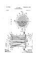
- Figure 1 shows in sectional elevation a filtercasing carrying a number of filter beds or units.
- Fig. 2 is a plan thereof with the cover removed, one-half of the filter-beds being shown in cross-section.
- Fig. 3 is a plan view of the interior arrangement of a small filter.
- Fig. 4 is'a sectional elevation,'on an enlarged scale, of a. filter-bed broken in length for want of space.
- Fig. 5 is a cross-sectional plan thereof.
- Fig. 6 shows in sectional elevation a single filtering unit within a suitable casing as adapted for domestic purposes.
- a filter in accordance with my invention in accordance with my invention I provide an outer pressureproof cylindrical casing A, of suitable capacity, carried on a base or support B, but which may be also mounted on wheels or on a carriage for convenience of transport.
- the casing A is provided with a removable cover a and also with a receiverb for the filtered water, preferably at the bottom of the casing.
- the cover a is secured by meansof hinged bolts 0, carried by the annular ring or flange (7.
- I provide a floor e, forming a roof to the receiver 12, and this is perforated to carry a number of perforated metal tubes f, arranged in concentric circles around a central unit, the number of which would vary according to the capacity of the filter-casing and the duty the filter is required to perform.
- the perforated tubes are screwed to the. floor e of the filter-casing 1A and are expanded in the floor or calked or a fluid-tight connection attained by any other suitable means.
- the perforated tubes. f serve to support filtering-cylinders and also to carry off and conduct the filtered water or other liquid to the receiver.
- the reader is referred to Fig. 4 for an enlarged detailed 1 construction of the filter-bed.
- cylinders consist of perforated metallic tubes g,whioh may be of aluminium, tinned copper, brass, or other suit-able metal.
- the perforated filtering-cylinders g are covered with a cloth straining-jacket 72., preferably of mercerized cotton cambric.
- the cotton cambric is mercerized according to the well-known process; but the stretching of the cloth is omitted, so that the shrinkage which' ensues causes the cloth to become more homogeneous, the interstices being filled up, and
- the cloth jacket h is of greater length thant-he tube 9 and is'tucked into the interior of the same, as shown in Fig. 4.
- the turnedin cloth jacket 7;. serves as a'flexible material to provide a fluid-tight joint between the capnut i and the cylinder gand as well as at the foot of the cylinder. If desired or requisite, additional resilient washers may be used at these points to efiect the object;
- an ordi nary n ut may be employed and the top screwed end of the tubefbe plugged up.
- a suitable aperture provided in the cover of the casing closed by a screwed plugj, I introduce into the casing A a quantity of filtering-earth,
- the inlet 70 for the unfiltered water or other liquid is disposed at the bottom of the casing 5 A, or if arranged at the top the pipe extends downward within the casing and is directed to impinge upon the plate e, so that the incoming rush of liquid rises and carries the filtering-earth particles upon the cloth jacket h of earths into the interstices of the cloth, and covers it with a smooth even surface of filtering material, the surface and molecular attraction of which arrest and retain all sus- I 5 pended matter, sl-imes, oil particles, or other filth contained in suspension in the liquid.
- the water or other liquid to be filtered passes through the filtering-cylinders into the annular chamber and into the perforated supporting-tubes f, which conduct the filtered water to the receiver b, from whence it can be drawn oif through thepipe Z to the'point of supply.
- - oxidizing or deoxidizing chemical agents orelements such as ashnimal charcoal, alkaline permanganates, and the likecan be added, if desired, to the filtering-earth media.
- the filtering-cylinders may be cleansed in situ by a reversed current .of air and filtered water.
- air under pressure may be forced through the pipe Z.
- the air and the filtered water in the receiver 12' is thus forced into the'interior of the supporting-tubes and throughthe filtering-cylinders, throwing off the dirty filter medium into the filter-case and out by way of a flush-pipe 012, provided for this purpose.
- I place asheet of perforated metal it above the filtering-cylinders and provide a Water-pipe 0 above this perforated metal plate. The water the filtering-cylinders g, jams the filtering parent.
- Fig. 3 I show in plan the internal arrangement of a small filter containing seven units only, which would be particularly suitable for filtering small volumes of liquid.
- the improved apparatus is particularly applicable and economical in cases where a large number of filtering-cylinders are employed for the delivery of very large volumes of water. Moreover, by the arrangement of the plurality of filtering units, as shown, in one common pressure-proof casing an immense filtering area can be obtained in com paratively-small bulk.
- the apparatus as described in addition to filtering water for domestic use is applicable for the filtration of water for a variety of pm: I poses and is capable of filtering bright and clear condensed water from papermakers and calico-printers drying-cylinders, and all such water, whether hot orcold, contaminated with oily particles from lubricants. In addition to the filtration of water, the apparatus is also applicable for filtering other liquids or beverages, such as beer and spirits.
- Fig. 6 I show a single filter-bed within a casing A applicable for use as a domestic filter.
- the inner drainage-tube f is securedv in position by means of nuts 19 p, resilient washers being employed, if necessary, to pro- ,vide a fluid-tight joint.
- the outer cylinder 9 is provided at each end with caps g g, bored for the passage ofthe inner tube f, while a cap-nut v binds the outer tube 9 in position.
- a modification in the method of securing the straining-cloth it upon the cylinderg is shown no in this figure.
- the caps g'g" are grooved and the straining-cloth h secured thereto by means of a cordor elastic.
- the inlet-pipe is marked q, and the delivery of the filtered water is by way of the inner drainage-tube f, as shown :15 by thearrows.
- the inlet-pipe q and deliverytube f are provided with suitable taps or valves.
- an outer perforated cylinder or' tube a space being left between the tubes for the free circulation of the fluid, the outer cylinder or tube being provided with a straining-jacket, preferably of 12 5 mercerized and unstretched cotton cambric, upon which is deposited a coating of filtering earth or media substantially as described and illustrated.
- a filter-bed consisting of an inner sup- 12o rality of filter-beds therein eachcomprising an inner supporting and draining tube and an outer perforated cylinder with a strainingjacket; upon said cylinder composed of mercerized cotton having a coating of filtering- .earth, and means for washing said filter-beds while in position, substantially as described.
Landscapes
- Chemical & Material Sciences (AREA)
- Chemical Kinetics & Catalysis (AREA)
- Filtering Materials (AREA)
Description
Patented .luly 3|, I900.
w. H. BARR. FILTERING APPARATUS.
2 Sheets-Sheet (No Model.)
w. H. BARR. FILTEBING APPARATUS.
Patented July 3!, I900.
2 Shank-Sheet 2.,
(No mum UNITED STATES PATENT OFFIEETT' WILLIAM HENRY BARR, or BURYQENGLAND.
rim-same APPARATUS.
SPECIFICATION forming part of Letters Patent 0. 651,592, dated July 31, 1900. Application filed January 23, 1900. Serial No. 2,502. (1% model.)
To all whom it may concern:
Be it known that I, WILLIAM HENRY BARR, Fellow of the Chemical Society, a subject of the Queen of Great Britain and Ireland, residing at Belgrave Place, Bury, in the county of Lancaster, England, have invented certain new and useful Improvements in Apparatus for the Filtration and Purification of Water, Spirits, Beer, Steam, and other Fluids, (for which I have made application for patent in Great Britain, No. 13,128, dated J one 24, 1899,) of which the following is a specification. My said invention relates to an improved apparatus for use in the filtration of water, beer, spirits, and other fluids.
The accompanying two sheets of drawings clearly illustrate my invention. Figure 1 shows in sectional elevation a filtercasing carrying a number of filter beds or units. Fig. 2 is a plan thereof with the cover removed, one-half of the filter-beds being shown in cross-section. Fig. 3 is a plan view of the interior arrangement of a small filter. Fig. 4 is'a sectional elevation,'on an enlarged scale, of a. filter-bed broken in length for want of space. Fig. 5 is a cross-sectional plan thereof. Fig. 6 shows in sectional elevation a single filtering unit within a suitable casing as adapted for domestic purposes.
Referring in the first place to Figs. 1 to 5, in constructing a filter in accordance with my invention I provide an outer pressureproof cylindrical casing A, of suitable capacity, carried on a base or support B, but which may be also mounted on wheels or on a carriage for convenience of transport. The casing A is provided with a removable cover a and also with a receiverb for the filtered water, preferably at the bottom of the casing. The cover a is secured by meansof hinged bolts 0, carried by the annular ring or flange (7. At the bottom of the casing A, I provide a floor e, forming a roof to the receiver 12, and this is perforated to carry a number of perforated metal tubes f, arranged in concentric circles around a central unit, the number of which would vary according to the capacity of the filter-casing and the duty the filter is required to perform. The perforated tubes are screwed to the. floor e of the filter-casing 1A and are expanded in the floor or calked or a fluid-tight connection attained by any other suitable means. The perforated tubes. f serve to support filtering-cylinders and also to carry off and conduct the filtered water or other liquid to the receiver. The reader is referred to Fig. 4 for an enlarged detailed 1 construction of the filter-bed. The filtering-.
cylinders consist of perforated metallic tubes g,whioh may be of aluminium, tinned copper, brass, or other suit-able metal.
fand an annular space maintained between the two by means of distance-piecesf',secured, top and bottom, to the inner tube f, as shown more particularly in the enlarged-views, Figs. 4 and 5. The perforated filtering-cylinders g are covered with a cloth straining-jacket 72., preferably of mercerized cotton cambric. The cotton cambric is mercerized according to the well-known process; but the stretching of the cloth is omitted, so that the shrinkage which' ensues causes the cloth to become more homogeneous, the interstices being filled up, and
the cloth is thus rendered very suitable as astraining material. The cloth jacket h is of greater length thant-he tube 9 and is'tucked into the interior of the same, as shown in Fig. 4. A cap-nut "L, screwed upon the top of the inner tube h, beds upon the top of the clothcovered tube g and jams the tube g tightly upon the floor e of the casing A The turnedin cloth jacket 7;. serves as a'flexible material to provide a fluid-tight joint between the capnut i and the cylinder gand as well as at the foot of the cylinder. If desired or requisite, additional resilient washers may be used at these points to efiect the object;
Instead of a cap-nut 'i, as illustrated, an ordi nary n ut may be employed and the top screwed end of the tubefbe plugged up. Through a suitable aperture provided in the cover of the casing, closed by a screwed plugj, I introduce into the casing A a quantity of filtering-earth,
water to be filtered. A pressure-gage? may we The cylinders k, g are placed upon the inner supporting-tubes r The filtering-earths are previously,
be attached to the casing to indicate the water-pressure within.
The inlet 70 for the unfiltered water or other liquid is disposed at the bottom of the casing 5 A, or if arranged at the top the pipe extends downward within the casing and is directed to impinge upon the plate e, so that the incoming rush of liquid rises and carries the filtering-earth particles upon the cloth jacket h of earths into the interstices of the cloth, and covers it with a smooth even surface of filtering material, the surface and molecular attraction of which arrest and retain all sus- I 5 pended matter, sl-imes, oil particles, or other filth contained in suspension in the liquid. The water or other liquid to be filtered, as :shown by the arrows, passes through the filtering-cylinders into the annular chamber and into the perforated supporting-tubes f, which conduct the filtered water to the receiver b, from whence it can be drawn oif through thepipe Z to the'point of supply.
- oxidizing or deoxidizing chemical agents orelements-such ashnimal charcoal, alkaline permanganates, and the likecan be added, if desired, to the filtering-earth media. A coating of filtering-earth of'from one-thirty-second to one-sixteenth of an inch in thickness deposited upon the straining-cloth suf- 'fices. for an etfective filter-bed, which coatingwould require from one to two and onehalfv ounces of media, such as kieselguhr, for a cylinder thirty inches in length and two inches in diameter.
When the filter-bed becomes thoroughly coated with foul matter and requires cleansing, liquid will'not pass through, sothat the dirty state of the filter becomes at once approved apparatus consists in the ease with with which the dirty filtering-cylinders can be removed, cleansed ,sterilized, and replaced in the filter-casing. To efiect this, the cover a of the filter-casing A is removed, and by unscrewing the cap-nuts 'i of the inner supporting tubes f'the filtertubes or cylinders g can "be readily withdrawn. The straining cloth It can then be removed and thoroughly cleansed and sterilized bywashing and boiling and be replaced in position, as before, upon the cylinder g. If desired, the filtering-cylinders may be cleansed in situ by a reversed current .of air and filtered water. To effect this, air under pressure may be forced through the pipe Z. The air and the filtered water in the receiver 12' is thus forced into the'interior of the supporting-tubes and throughthe filtering-cylinders, throwing off the dirty filter medium into the filter-case and out by way of a flush-pipe 012, provided for this purpose. j To assist the cleansing, I place asheet of perforated metal it above the filtering-cylinders and provide a Water-pipe 0 above this perforated metal plate. The water the filtering-cylinders g, jams the filtering parent. ,An important feature of my im- 1 from the pipe 0 is broken up into a shower by the perforations in the plate and falls upon the filtering-jackets. It will be understood that the foul filtering medium is thrown away and replaced by a fresh supply, which is deposited, as described, upon the strainingcloth jackets.
The number of filtering units employed may vary-according to the volume of liquid to be filtered. In Fig. 3 I show in plan the internal arrangement of a small filter containing seven units only, which would be particularly suitable for filtering small volumes of liquid.
The improved apparatus is particularly applicable and economical in cases where a large number of filtering-cylinders are employed for the delivery of very large volumes of water. Moreover, by the arrangement of the plurality of filtering units, as shown, in one common pressure-proof casing an immense filtering area can be obtained in com paratively-small bulk.
The apparatus as described in addition to filtering water for domestic use is applicable for the filtration of water for a variety of pm: I poses and is capable of filtering bright and clear condensed water from papermakers and calico-printers drying-cylinders, and all such water, whether hot orcold, contaminated with oily particles from lubricants. In addition to the filtration of water, the apparatus is also applicable for filtering other liquids or beverages, such as beer and spirits.
In Fig. 6 I show a single filter-bed within a casing A applicable for use as a domestic filter. The inner drainage-tube f is securedv in position by means of nuts 19 p, resilient washers being employed, if necessary, to pro- ,vide a fluid-tight joint. The outer cylinder 9 is provided at each end with caps g g, bored for the passage ofthe inner tube f, while a cap-nut v binds the outer tube 9 in position. A modification in the method of securing the straining-cloth it upon the cylinderg is shown no in this figure. The caps g'g" are grooved and the straining-cloth h secured thereto by means of a cordor elastic. The inlet-pipe is marked q, and the delivery of the filtered water is by way of the inner drainage-tube f, as shown :15 by thearrows. The inlet-pipe q and deliverytube f are provided with suitable taps or valves.
I declare that what I claim is--.
porting and drainage tube, an outer perforated cylinder or' tube, a space being left between the tubes for the free circulation of the fluid, the outer cylinder or tube being provided with a straining-jacket, preferably of 12 5 mercerized and unstretched cotton cambric, upon which is deposited a coating of filtering earth or media substantially as described and illustrated.
2. In a filtering apparatus, a casing, a plux30 1. A filter-bed consisting of an inner sup- 12o rality of filter-beds therein eachcomprising an inner supporting and draining tube and an outer perforated cylinder with a strainingjacket; upon said cylinder composed of mercerized cotton having a coating of filtering- .earth, and means for washing said filter-beds while in position, substantially as described.
In witness whereof I have hereunto set my hand-in presence of two witnesses.
Wimessesz JOSHUA ENcrWIsIJE, WALTER HAOKI'NG.
WILLIAM HENRY BARR.
Priority Applications (1)
| Application Number | Priority Date | Filing Date | Title |
|---|---|---|---|
| US250200A US654592A (en) | 1900-01-23 | 1900-01-23 | Filtering apparatus. |
Applications Claiming Priority (1)
| Application Number | Priority Date | Filing Date | Title |
|---|---|---|---|
| US250200A US654592A (en) | 1900-01-23 | 1900-01-23 | Filtering apparatus. |
Publications (1)
| Publication Number | Publication Date |
|---|---|
| US654592A true US654592A (en) | 1900-07-31 |
Family
ID=2723161
Family Applications (1)
| Application Number | Title | Priority Date | Filing Date |
|---|---|---|---|
| US250200A Expired - Lifetime US654592A (en) | 1900-01-23 | 1900-01-23 | Filtering apparatus. |
Country Status (1)
| Country | Link |
|---|---|
| US (1) | US654592A (en) |
Cited By (18)
| Publication number | Priority date | Publication date | Assignee | Title |
|---|---|---|---|---|
| US2494534A (en) * | 1944-03-16 | 1950-01-17 | Us Hoffman Machinery Corp | Coolant filter system |
| US2545374A (en) * | 1949-08-11 | 1951-03-13 | Wm W Nugent & Co Inc | Two-stage filter in single housing |
| US2638229A (en) * | 1948-05-26 | 1953-05-12 | Bowser Inc | Combined filter and hose reel |
| US2732949A (en) * | 1956-01-31 | Treatment of thixotropic materials | ||
| US2744632A (en) * | 1950-12-23 | 1956-05-08 | Indiana Commerical Filters Cor | Filtering screen assembly |
| US2748950A (en) * | 1951-09-13 | 1956-06-05 | Charles M Tursky | Fluid filter |
| US2921686A (en) * | 1956-12-03 | 1960-01-19 | Alpha Tank Company Inc | Fluid filtering apparatus with removable filter holder |
| US2925913A (en) * | 1956-07-30 | 1960-02-23 | Poroloy Equipment Inc | Filter unit |
| US2981416A (en) * | 1957-10-23 | 1961-04-25 | Gen Filter Co | Apparatus for the cleaning of filtering equipment |
| US3037634A (en) * | 1958-06-16 | 1962-06-05 | Bowser Inc | Water filter |
| US3097165A (en) * | 1959-10-26 | 1963-07-09 | Bendix Corp | Fuel filtering and heater combination |
| US3253714A (en) * | 1963-10-01 | 1966-05-31 | Croll Reynolds Engineering Com | Pressure filter |
| US4297211A (en) * | 1977-05-20 | 1981-10-27 | Inkomag | Filtering apparatus |
| WO1988008475A1 (en) * | 1987-04-30 | 1988-11-03 | Tolo, Incorporated | Universally-adaptable pool water filter structures |
| US5028323A (en) * | 1989-10-31 | 1991-07-02 | Gould Leon B | Filter for corrosive liquids |
| US20060151368A1 (en) * | 2003-04-10 | 2006-07-13 | Shawndra Products | Particulate filter for oil |
| US20100181243A1 (en) * | 2006-08-03 | 2010-07-22 | Mann+Hummel Gmbh | Filter Unit Having a Conical Thread |
| USRE46080E1 (en) * | 2004-06-17 | 2016-07-26 | Hydac Filtertechnik Gmbh | Filtering apparatus and filter element |
-
1900
- 1900-01-23 US US250200A patent/US654592A/en not_active Expired - Lifetime
Cited By (20)
| Publication number | Priority date | Publication date | Assignee | Title |
|---|---|---|---|---|
| US2732949A (en) * | 1956-01-31 | Treatment of thixotropic materials | ||
| US2494534A (en) * | 1944-03-16 | 1950-01-17 | Us Hoffman Machinery Corp | Coolant filter system |
| US2638229A (en) * | 1948-05-26 | 1953-05-12 | Bowser Inc | Combined filter and hose reel |
| US2545374A (en) * | 1949-08-11 | 1951-03-13 | Wm W Nugent & Co Inc | Two-stage filter in single housing |
| US2744632A (en) * | 1950-12-23 | 1956-05-08 | Indiana Commerical Filters Cor | Filtering screen assembly |
| US2748950A (en) * | 1951-09-13 | 1956-06-05 | Charles M Tursky | Fluid filter |
| US2925913A (en) * | 1956-07-30 | 1960-02-23 | Poroloy Equipment Inc | Filter unit |
| US2921686A (en) * | 1956-12-03 | 1960-01-19 | Alpha Tank Company Inc | Fluid filtering apparatus with removable filter holder |
| US2981416A (en) * | 1957-10-23 | 1961-04-25 | Gen Filter Co | Apparatus for the cleaning of filtering equipment |
| US3037634A (en) * | 1958-06-16 | 1962-06-05 | Bowser Inc | Water filter |
| US3097165A (en) * | 1959-10-26 | 1963-07-09 | Bendix Corp | Fuel filtering and heater combination |
| US3253714A (en) * | 1963-10-01 | 1966-05-31 | Croll Reynolds Engineering Com | Pressure filter |
| US4297211A (en) * | 1977-05-20 | 1981-10-27 | Inkomag | Filtering apparatus |
| WO1988008475A1 (en) * | 1987-04-30 | 1988-11-03 | Tolo, Incorporated | Universally-adaptable pool water filter structures |
| US5008008A (en) * | 1987-04-30 | 1991-04-16 | James Lockshaw | Universally adaptable pool water filter structure |
| US5028323A (en) * | 1989-10-31 | 1991-07-02 | Gould Leon B | Filter for corrosive liquids |
| US20060151368A1 (en) * | 2003-04-10 | 2006-07-13 | Shawndra Products | Particulate filter for oil |
| USRE46080E1 (en) * | 2004-06-17 | 2016-07-26 | Hydac Filtertechnik Gmbh | Filtering apparatus and filter element |
| US20100181243A1 (en) * | 2006-08-03 | 2010-07-22 | Mann+Hummel Gmbh | Filter Unit Having a Conical Thread |
| US8097154B2 (en) * | 2006-08-03 | 2012-01-17 | Mann+Hummel Gmbh | Filter unit having a conical thread |
Similar Documents
| Publication | Publication Date | Title |
|---|---|---|
| US654592A (en) | Filtering apparatus. | |
| US2392901A (en) | Filter | |
| US1787577A (en) | Filter | |
| US3384240A (en) | Activated charcoal filter assembly having backwash means | |
| US360441A (en) | Filtering apparatus | |
| US1407763A (en) | Filtering apparatus | |
| US2269725A (en) | Filter | |
| US3170873A (en) | Water filter-separator | |
| US191131A (en) | Improvement in filtering apparatus | |
| JPS59179106A (en) | Tangential filter apparatus and instllation containing same | |
| US2593639A (en) | Filter | |
| US999759A (en) | High-pressure filter. | |
| US1270042A (en) | Filter. | |
| US620451A (en) | Rudolf helwig | |
| US1246850A (en) | Automatic self-cleaning filter. | |
| US864345A (en) | Water-filter. | |
| US609769A (en) | Domestic or other filter | |
| US1750997A (en) | Liquid filter | |
| US560261A (en) | Filter | |
| US2051126A (en) | Naphtha cleaning plant | |
| US1758412A (en) | Liquid filter | |
| US2079755A (en) | Filter | |
| US2233981A (en) | Filter | |
| US311257A (en) | piefke | |
| US1358333A (en) | Filter, cleaner, or washer for air |