US6534995B1 - Circuit for detecting a cooling device in a computer system - Google Patents
Circuit for detecting a cooling device in a computer system Download PDFInfo
- Publication number
- US6534995B1 US6534995B1 US09/766,481 US76648101A US6534995B1 US 6534995 B1 US6534995 B1 US 6534995B1 US 76648101 A US76648101 A US 76648101A US 6534995 B1 US6534995 B1 US 6534995B1
- Authority
- US
- United States
- Prior art keywords
- cooling device
- computer system
- power
- signal
- power management
- Prior art date
- Legal status (The legal status is an assumption and is not a legal conclusion. Google has not performed a legal analysis and makes no representation as to the accuracy of the status listed.)
- Expired - Lifetime, expires
Links
Images


Classifications
-
- G—PHYSICS
- G06—COMPUTING; CALCULATING OR COUNTING
- G06F—ELECTRIC DIGITAL DATA PROCESSING
- G06F1/00—Details not covered by groups G06F3/00 - G06F13/00 and G06F21/00
- G06F1/16—Constructional details or arrangements
- G06F1/20—Cooling means
- G06F1/206—Cooling means comprising thermal management
-
- Y—GENERAL TAGGING OF NEW TECHNOLOGICAL DEVELOPMENTS; GENERAL TAGGING OF CROSS-SECTIONAL TECHNOLOGIES SPANNING OVER SEVERAL SECTIONS OF THE IPC; TECHNICAL SUBJECTS COVERED BY FORMER USPC CROSS-REFERENCE ART COLLECTIONS [XRACs] AND DIGESTS
- Y02—TECHNOLOGIES OR APPLICATIONS FOR MITIGATION OR ADAPTATION AGAINST CLIMATE CHANGE
- Y02D—CLIMATE CHANGE MITIGATION TECHNOLOGIES IN INFORMATION AND COMMUNICATION TECHNOLOGIES [ICT], I.E. INFORMATION AND COMMUNICATION TECHNOLOGIES AIMING AT THE REDUCTION OF THEIR OWN ENERGY USE
- Y02D10/00—Energy efficient computing, e.g. low power processors, power management or thermal management
Definitions
- This invention relates to computer systems. More particularly, this invention relates to detecting a cooling device in a computer system.
- CPUs and other components such as hard disks and graphics processors increase their operating frequency, they consume more power and consequentially generate more heat.
- increased transistor density has also caused some components to produce more heat. Because components are designed to operate within a certain temperature range, this increased heat generation may cause many problems. Many errors can occur once a component begins to overheat. For example, system crashes, random reboots, and system lockup are common errors caused by an overheating processor. Furthermore, extended high temperatures may damage the components themselves. Thus in modem computer systems, specialized cooling systems are required to prevent heat-related problems.
- a passive heat sink is simply a piece of metal attached to the component in such a way that it draws heat away from the component and radiates this heat into the surrounding air.
- fins were added to heat sinks. Fins increase the surface area of a heat sink, allowing the heat sink to radiate more heat.
- a fan placed somewhere in the computer case assists passive heat sinks by circulating cooler air across the heat sink, allowing more heat to be radiated away.
- Most computer systems include, at a minimum, one or more passive heat sinks and a fan located somewhere in the case. Some computer systems may contain other cooling devices in addition to or instead of fans and/or passive heat sinks. In any computer system, failure of a cooling device may result in one or more of the system components overheating.
- a passive heat sink may no longer satisfactorily remove enough heat.
- An active heat sink is a passive heat sink connected to a dedicated fan or other active cooling device. The fan is attached so that it blows directly over the heat sink to provide additional cooling.
- Some heat sinks also include a Peltier cooler, which is a solid-state device that pumps heat from one of its sides to the other. Including a Peltier cooler may increase cooling of a particular component, but the Peltier element may also increase the overall heat generated in the system.
- an active heat sink configuration may be capable of radiating enough heat away from the component to prevent overheating, it also has its drawbacks.
- active cooling devices such as fans may be susceptible to failure. Fans used in computer systems are often inexpensive and unreliable, making them even more likely to malfunction. If a cooling device such as a fan or a Peltier cooler does malfunction, active heat sinks are often incapable of adequately cooling the component anymore. This may happen because the metal heat sink is smaller than it would have been if it had been designed to be used without the cooling device. Additionally, since other cooling measures such as the system fan were no longer as necessary to cooling that particular component after the addition of the dedicated cooling device, the other cooling measures may have been placed so that they no longer directly cool the active heat sink. In heat sinks incorporating Peltier coolers, the extra heat generated by the Peltier element creates an even greater risk to the component if the fan or other cooling device fails.
- heat sinks, fans and other cooling devices can usually prevent heat-related problems from endangering system performance and components.
- cooling devices such as fans may not always be very reliable components, and cooling device failure may endanger components and may also have detrimental effects on system performance.
- Prior art systems have recognized this possibility.
- alarm circuits that detect processor overheating are available. These alarm circuits may monitor the processor fan power supply, the temperature of the processor, or the airflow through a fan that cools a processor. These circuits are configured to generate an alarm when they detect a condition that may lead to processor overheating.
- cooling device failure is an important concern in a computer system. If a cooling device fails, components may not be properly cooled. Expensive components such as the processor may overheat, causing unreliable performance and possibly even destroying the components themselves. Even if the component is only connected to a passive heat sink, the passive heat sink may depend on a different cooling device such as a fan used to cool a power supply to circulate enough air across the heat sink or to otherwise allow the heat sink to adequately draw enough heat away from the component.
- a computer system includes a cooling device configured to cool a component, a power supply configured to power the component, and a cooling device detection circuit configured to detect the cooling device.
- the cooling device detection circuit includes a detection stage and a power management stage. The detection stage is configured to detect the cooling device by sensing an indication that the cooling device is functioning.
- the power management stage is coupled to the detection stage and is configured to turn the power supply off if the cooling device is not detected.
- the cooling device may include a fan that is part of an active heat sink coupled to a CPU.
- the cooling device may include a fan configured to cool a main power supply in the computer system.
- the indication that the cooling device is functioning may, in some embodiments, include an indication that current is flowing across the cooling device.
- the indication that the cooling device is functioning may include a tachometer signal.
- the power management stage may be configured to receive an input indicating whether the computer system is in a power conservation mode in one embodiment.
- the power management stage may, in some embodiments, receive an input indicating whether the computer system is requesting that the cooling device be turned off. If the computer system is in a power conservation mode or requesting that the cooling device be turned off, the power management stage may be configured to turn the cooling device off.
- the power management stage may receive an input indicating whether the voltages in the computer system have stabilized in some embodiments.
- the power management stage may turn the power supply off by deasserting a signal that controls the power supply. A south bridge may generate the signal.
- a method for detecting a cooling device in a computer system includes detecting the cooling device by sensing an indication that the cooling device is functioning and if the cooling device is not detected, turning off a power supply that provides a component cooled by the cooling device with power.
- the component being cooled may be a CPU.
- the method may also include sensing whether a plurality of voltages in the computer system have stabilized, sensing whether the computer system is in a power conservation mode, and/or sensing whether the computer system is requesting that the fan be turned off.
- the indication that the cooling device is functioning may be sensed by sensing a current flowing from a ground terminal of the cooling device to ground in some embodiments.
- sensing may include sensing a tachometer signal.
- the circuit may include a current-detecting device configured to sense current flowing from a ground terminal of a cooling device to ground.
- the circuit may also include a signaling device configured to assert a detection signal if the current-detecting device senses the current and to deassert the detection signal if the current-detecting device does not sense the current.
- the cooling device detection circuit may include a diode and a transistor. The diode may be coupled between a ground terminal of the cooling device and ground so that when current flows from the ground terminal to ground a voltage drop is produced across the diode.
- the transistor may be configured to turn on in response to the voltage drop being produced across the diode.
- the signaling device may include a transistor configured to turn on in response the current-detecting device sensing the current and to turn off in response to the current-detecting device not sensing the current in one embodiment.
- the circuit may include an interface configured to generate an interrupt that causes an alarm.
- the circuit includes a tachometer-detecting device configured to sense a tachometer signal provided by the fan.
- the circuit may also include a signaling device configured to assert a detection signal if the tachometer-detecting device senses the tachometer signal and to keep the detection signal unasserted if the tachometer-detecting device does not sense the tachometer signal.
- the tachometer-detecting device may be configured to sense the tachometer signal by continuously monitoring the tachometer signal.
- the tachometer-detecting device may be configured to sense the tachometer signal by latching a first pulse of the tachometer signal.
- the fan detection circuit may include an interface configured to initiate an interrupt that causes an alarm if the detection signal is not asserted.
- FIG. 1 is a block diagram of a computer system
- FIG. 2 shows a block diagram of a cooling device detection circuit
- FIG. 3 is a block diagram of a computer system containing a cooling device detection circuit
- FIG. 4 shows one embodiment of a detection stage of a cooling device detection circuit
- FIG. 5 shows another embodiment of a detection stage of a cooling device detection circuit
- FIG. 6 shows one embodiment of a power management stage of a cooling device detection circuit
- FIG. 7 shows another embodiment of a power management stage of a cooling device detection circuit
- FIGS. 8A and 8B each show an embodiment of a method for detecting a cooling device
- FIGS. 9A and 9B each show an embodiment of a power management method
- FIG. 10 shows another embodiment of a detection stage of a cooling device detection circuit
- FIG. 11 shows another embodiment of a detection stage of a cooling device detection circuit
- FIG. 12 shows another embodiment of a power management stage of a cooling device detection circuit
- FIG. 13 shows another embodiment of a power management stage of a cooling device detection circuit.
- FIG. 1 shows one example of a computer system 100 .
- the computer system 100 has one or more central processing units (CPUs) 101 coupled by a processor bus 103 to a north bridge 105 .
- CPUs central processing units
- Each CPU may be coupled to an active heat sink that includes a fan 150 and a passive heat sink 135 , where the fan 150 is coupled to the passive heat sink 135 so that the fan 150 can circulate hot air away from the passive heat sink 135 .
- the fan 150 may not be part of an active heat sink and thus not coupled to the passive heat sink 135 even though the fan 150 may still be configured to circulate hot air away from the heat sink 135 .
- the computer system 100 may also include additional fans (not shown).
- the case containing the computer system 100 may include a fan that cools the power supply.
- the computer system 100 may include other cooling devices, such as Peltier coolers.
- one or more voltage regulators 145 may provide power to the processor(s) 101 .
- the north bridge 105 also known as a system controller, may contain such devices as a system bus interface, a memory controller, a Peripheral Component Interconnect (PCI) bus controller, and an Accelerated Graphics Port (AGP).
- PCI Peripheral Component Interconnect
- AGP Accelerated Graphics Port
- the north bridge 105 forwards data, address and control signals between the processor bus, the PCI bus and the memory.
- the north bridge 105 is coupled to a main memory 115 by a data and address bus 125 .
- the PCI bus 104 couples the north bridge 105 to a south bridge 106 .
- the south bridge 106 also known as a peripheral bus controller, may contain devices such as a PCI to Industry Standard Architecture (ISA) bridge, an Enhanced Integrated Device Electronics (EIDE) controller, and a Universal Serial Bus (USB) controller.
- the south bridge 106 may perform administrative functions such as interrupt management, clock/calendar/timer functions, configuration management, power supply control, and power-on signal sequencing.
- the PCI bus 104 is connected to one or more PCI devices 102 .
- cooling devices used in computer systems may fail. If a cooling device fails, devices such as active or passive heat sinks may be unable to remove heat adequately and component malfunction or damage may result.
- FIG. 2 shows a block diagram of a cooling device detection circuit 200 designed to detect an indication that a cooling device 210 is functioning.
- the circuit 200 has a detection stage 220 .
- the detection stage 220 is configured to sense an indication that the cooling device 210 is functioning.
- detection stage 220 may be configured to detect current flowing through the cooling device 210 .
- the detection stage generates a Device_Detected signal that shows whether the detecting stage received the indication that the cooling device 210 is functioning.
- the cooling device detection circuit 200 may also include a power management stage 230 .
- the power management stage 230 may control the Power_On signal.
- the Power_On signal tells the computer system to start or stop powering a component cooled by the cooling device 210 . If the Device_Detected signal indicates that the cooling device is not functioning, the power management stage 230 may tell the computer system to stop powering the component by causing the Power_On signal to be deasserted. In some embodiments, the power management stage may prevent the Power_On signal from being asserted if the cooling device is not detected.
- the Power_On signal may, in some embodiments, be generated by another device in the computer system such as a south bridge.
- the power management stage may be configured to control the Power_On signal in order to start or stop powering a component cooled by a cooling device.
- the Power_On signal may instead be generated by the power management stage 230 .
- the power management stage may also be configured to turn the cooling device on or off.
- certain embodiments of the power management stage 230 may also receive an additional signal, Device_On, indicating whether the computer system has requested that the cooling device be turned off or on.
- the power management stage may be configured to ignore the Device_Detected signal when the system is requesting that the cooling device be turned off (e.g. when the system is in a low power state).
- the power management stage may, in one embodiment, turn the cooling device on or off in response to the Device_On signal.
- the power management stage may receive a signal Power_Good indicating that certain voltages on the motherboard have stabilized.
- the power management stage may allow the cooling device to be turned on by allowing the Power_On signal to be asserted during the time that Power_Good is not yet asserted.
- the power management stage may ignore the Device_Detected signal until the Power_Good signal indicates that the voltages on the motherboard have stabilized. If the cooling device is not detected before Power_Good is asserted, the power management stage may then deassert Power_On.
- the cooling device detection circuit 200 has been included in computer system 100 .
- the cooling device detection circuit 200 may be used to detect a cooling device such as the fan 150 .
- the cooling device detection circuit 200 is configured to receive an indication that the cooling device is functioning and to output a Device_Detected signal accordingly. In the system shown in FIG. 1, this may correlate to the fan 150 that is part of the active heat sink coupled to the processor 101 .
- the detection stage 220 may be configured to detect a different cooling device in the computer system, such as a power supply fan. In other embodiments, the detection stage 220 may be configured to detect an indication that a cooling device other than a fan is functioning.
- the detection stage may be configured to detect an indication that a Peltier cooler, a water cooler-type cooler device or a vapor phase refrigeration cooler is functioning. If the Device_Detected signal does not indicate that the device is functioning, some embodiments of the detection circuit 200 may set off an alarm. The detection circuit may set off an alarm by generating an interrupt.
- the cooling device detection circuit 200 may include a power management stage.
- the Device_Detected signal may be an input to the power management stage of the cooling device detection circuit 200 . If the Device_Detected signal indicates that the cooling device is not detected (e.g., the Device_Detected signal is not asserted), the power management stage may cause the computer system 100 to stop powering one or more components cooled by the cooling device.
- the components may be processors, graphics processors and/or hard drives.
- the cooling device may be the fan 150 and the affected component may be the processor 101 . If the cooling device is not detected, the power management stage may cause the voltage regulator 145 to stop powering the processor 101 by deasserting the Power_On signal.
- the voltage regulator may be regulating a voltage supplied by another power supply in computer system 100 , and the power management stage may turn off that other power supply if the cooling device is not detected.
- the Power_On signal controlling voltage regulator 145 may be provided by the power management stage.
- the Power_On signal may be provided by another component such as a south bridge and the power management stage may be able to control the Power_On signal in such a way that it can deassert Power_On or prevent Power_On from being asserted if the cooling device is not detected.
- FIG. 4 shows a block diagram of one embodiment of a detection stage 220 that may be used in a cooling device detection circuit 200 .
- Device connectors 301 and 302 may be terminals to which the cooling device should be connected. If the cooling device is connected and receiving power, current will flow from the voltage supply terminal 301 to the ground terminal 302 .
- the detection stage 220 may be coupled to the ground terminal 302 and configured to sense the current across the cooling device.
- the detection stage 220 may be configured to sense the current as an indication that the device is functioning. If the detection stage 220 senses current through the device, the detection stage asserts Device_Detected to indicate that the device was detected. If the current through the device is not sensed, the detection stage keeps the Device_Detected signal unasserted.
- FIG. 5 shows a block diagram of different embodiment of a detection stage 220 that may be used in a cooling device detection circuit 200 .
- the cooling device may be a fan.
- this embodiment senses a fan's tachometer output.
- the detection stage 220 senses an indication that the fan is functioning based on the tachometer output. If the detection stage 220 detects the indication of fan rotation, it asserts Device_Detected.
- the detection stage 220 may sense a first pulse on the tachometer output as an indication that the fan is functioning. If the first pulse is sensed, the detection stage may then assert the Device_Detected signal.
- this circuit may also be capable of detecting that the fan is spinning properly throughout its operation.
- the detection stage 220 may continuously monitor the tachometer output.
- this detection stage may detect not only that the fan is turned on, but also that it is rotating. However, these embodiments of the detection stage require that the fan being monitored have a tachometer output. In other embodiments, any signal indicating that a cooling device is functioning may be monitored.
- FIG. 6 shows a block diagram of one embodiment of a power management stage 230 .
- the power management stage 230 is configured to receive the Device_Detected signal from a detection stage of the cooling device detection circuit.
- the cooling device may be a fan and Device_Detected may also indicate whether the fan is rotating.
- the computer system employing a cooling device detection circuit including the power management stage 230 may have power management features, including power conservation modes such as sleep, suspend or standby where the computer system enters one or more low power states.
- power conservation modes such as sleep, suspend or standby where the computer system enters one or more low power states.
- a component When in a low power state, a component may operate at a lower voltage and thus generate less heat. In some situations, the component may no longer need the cooling device while in a low power state. Thus, in some embodiments, the computer system may turn of the cooling device during a low power state. If the cooling device is off, the detection stage may no longer detect the cooling device.
- the power management stage may be configured to ignore the signal from the detection stage while the computer system is in the low power state.
- the power management stage 230 may receive a Device_On signal indicating whether whether the system is in a low power state.
- the Device_On signal may also indicate that the system has turned the cooling device off.
- the power management stage may be configured to turn the cooling device off when the computer system is in a low power state.
- FIG. 7 a block diagram of a different embodiment of a power management stage 230 is shown.
- the power management stage 230 receives Device_Detected and Power_Good as inputs.
- Power_Good may be a signal that indicates whether certain voltages on the motherboard have stabilized. Until these voltages have stabilized, Device_Detected may not correctly indicate whether the device is present and receiving power. As a result, the power management stage 230 may be configured to ignore Device_Detected until Power_Good indicates that the voltages have stabilized.
- the power management stage 230 may receive all three signals, Device_Detected, Device_On and Power_Good, as inputs. Additional signals may also be input to the power management stage 230 in certain embodiments.
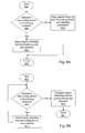
- FIG. 8A illustrates one embodiment of a method for detecting a cooling device in a computer system. If an indication that the cooling device is functioning is received at 805 , a signal is asserted indicating that the cooling device was detected as indicated at 810 . If the indication is not received, the signal is kept unasserted to indicate that the cooling device was not detected, shown at 815 .
- the signal may be a signal such as the Device_Detected signal shown in FIGS. 3-6.
- the indication that the cooling device is functioning may be an indication that current is flowing through the cooling device or, in embodiments where the cooling device has a tachometer, an indication that the cooling device is rotating.
- FIG. 8B shows a slightly different embodiment of a method for detecting a cooling device in a computer system.
- the indication that the cooling device is functioning is continuously monitored.
- the method again checks the indication that the device is functioning at 806 . If at any point the device is not detected, the signal is deasserted to indicate that the device is not detected at 816 .
- FIG. 9A shows a flow chart for one embodiment of a power management method. If there is an indication that the cooling device is not functioning (e.g., Device_Detected is unasserted), the computer system is instructed to stop powering devices affected by the missing or malfunctioning cooling device as indicated at 915 .
- the power may be turned off by deasserting a power supply signal (e.g. Power_On).
- the power supply signal may not have been asserted yet, and the power supply signal may instead be kept desasserted if the cooling device is not detected. For example, in some embodiments certain components in the system, including the cooling device, may be powered first.
- Powering the cooling device allows the cooling device to be detected in embodiments where the detection circuit senses current, rotation, etc. In some embodiments, other components in the system such as those that are cooled by the cooling device may not be powered until the cooling device has been detected. In one embodiment, when there is an indication that the cooling device is functioning, the power supply signal may be left alone, shown at 910 . In some embodiments, this may involve not disturbing a power supply signal that has been generated by another device. In other embodiments, leaving the power supply signal alone may involve continuing to assert a power supply signal. Still other embodiments may instead assert the power supply signal when there is an indication that the cooling device is functioning.
- FIG. 9B shows another embodiment of a power management method.
- an indication that the cooling device is functioning/not functioning may be ignored as indicated at 906 . In some embodiments, this may allow the cooling device to be powered so that the detection circuit can detect it. Once the voltages have stabilized, however, the indication that the cooling device is functioning may be considered again at 916 . If the indication that the cooling device is functioning is not sensed, the computer system is instructed to stop powering the devices that were to be cooled by the cooling device.
- Another factor that may be considered is whether the system has turned the cooling device off, shown at 911 .
- a computer system may turn off cooling devices while in a power conservation mode. If the computer system has turned the cooling device off (e.g. Device_On is unasserted), the indication that the cooling device is functioning/not functioning may be ignored until the computer system turns the cooling device back on. Some embodiments may consider both of these additional factors, while others may only consider one or the other.
- FIG. 10 shows another embodiment of a detection stage 220 .
- Cooling device terminals 301 and 302 are input terminals to which the cooling device may be connected. If the cooling device is connected and receiving power, current will flow from the 12 V supply terminal 301 to the ground terminal 302 .
- the detection stage senses the current across the cooling device.
- the detection stage may include a diode D 1 placed between the cooling device's ground terminal 302 and ground, a transistor Q 1 and a resistor R 1 . If current is flowing across the cooling device terminals, current will flow through the diode D 1 , producing a voltage drop across the diode D 1 . This voltage drop across diode D 1 causes transistor Q 1 to turn on.
- transistor Q 1 When transistor Q 1 turns on, it asserts the Device_Detected# signal by pulling the active low signal Device_Detected# low.
- the Device_Detected signal may be provided to a power management stage in some embodiments. In other embodiments, the Device_Detected# signal may be provided to another component in the computer system such as an alarm circuit. When no current flows across the diode D 1 , Q 1 remains off and Device_Detected is not asserted.
- the cooling device detecting stage is configured to monitor the cooling device's tachometer.
- the cooling device detecting stage may include three transistors, Q 2 , Q 3 and Q 4 .
- the cooling device tachometer outputs a square wave with a frequency proportional to the cooling device's rotational speed.
- a voltage is applied to, transistor Q 2 turns on.
- Q 2 turns on, current flows across resistor R 2 , causing a voltage drop across R 2 .
- the voltage across R 2 causes transistor Q 4 to turn on.
- the cooling device detection circuit may also have a power management stage.
- a power management stage is shown in FIG. 12 .
- This embodiment may include transistor Q 5 , resistors R 5 and R 6 , capacitor C 1 , and transistor Q 6 .
- An active low Device_Detected# signal may be provided from a detection stage such as those shown in FIGS. 3-4 and 8 - 9 .
- An active high Power_On signal may be asserted by another components in the system such as a south bridge. If the cooling device is not detected, Device_Detected# is high, causing Q 6 to turn on, deasserting Power_On. When the cooling device is detected, the voltage applied to the gate of Q 6 is low, so Q 6 does not turn on and Power_On is not deasserted by the power management stage.
- a computer system may turn off the cooling device in certain situations, such as when the computer system is entering a power conservation stage.
- an active low signal, Device_On# indicating that the computer system is not in a low power state and/or that the cooling device has been turned on may also be provided to the power management stage.
- This signal is applied to the base of transistor Q 5 , so when the cooling device is on and Device_On# is low, Q 5 does not turn on and the voltage applied to the gate of transistor Q 6 depends on Device_Detected#, as explained above.
- Device_On# is high, causing Q 5 to turn on and pull the voltage applied to the gate of Q 6 low.
- a voltage divider including resistors R 5 and R 6 may be placed across the 12 V source to lower the voltage input to the gate of Q 6 .
- the capacitor C 1 provides noise immunity to Q 6 and also adds hystereses to the circuit.
- the power management stage controls an active high signal Power_On that is provided by another component in the computer system by either deasserting Power_On or leaving it undisturbed. In other embodiments, however, the power management stage may generate the Power_On# signal.
- Table 1 provides a truth table for the operation of the embodiment shown in FIG. 12 .
- Device_On# is inactive high, indicating that the system has requested the cooling device be turned off
- the Device_Detected# signal is ignored. Therefore, whenever the system has turned the cooling device off, the power management stage leaves the Power_On signal alone.
- the Device_Detected# signal is monitored by the power management stage. When no current is detected, Device_Detected# is inactive high and the power management stage drives Power_On inactive low, instructing the system to turn the power off.
- FIG. 13 Another embodiment of a power management stage is illustrated in FIG. 13 .
- the embodiment shown in FIG. 13 may receive two inputs.
- the Device_Detected signal may be received from a detection stage such as those shown in FIGS. 4-5 and 9 - 10 .
- An active low signal, Power_Good# indicating that certain voltages on the motherboard have stabilized, may also be provided to the power management stage.
- the Power_Good# signal may be generated by a south bridge or a power supply.
- the power management stage controls an active low signal Power_On# by deasserting the signal in certain circumstances.
- Power_On# is approximately equal to Power#, which may be generated by another component in the computer system to indicate that the system power should be tuned on (when Power# is low) or off (when Power# is high).
- the power management stage may generate the Power_On# or Power# signals itself instead of only controlling the Power_On# signal.
- the power management stage may, in some embodiments, include four transistors Q 7 -Q 10 and four resistors R 7 -R 11 .
- Q 7 turns on. This causes Q 9 to turn off and Q 10 to turn on.
- Power_On# is approximately equal to Power# (while the voltages are not equal, the signals are equivalent from a binary state standpoint). If the Device_Detected signal is unasserted, indicating that the cooling device was not detected, Q 7 does not turn on. As a result, Q 9 turns on unless, as will be discussed in more detail below, the Power_Good# signal has not been asserted.
- Power_On# is active low in this embodiment, a high Power_On# means that Power_On# is unasserted.
- Power_On# may be a control signal to a system power supply such that an unasserted Power_On# will cause the computer system to stop powering components cooled by the cooling device that was not detected.
- this embodiment of the power management stage allows Power_On# to be asserted before the cooling device is detected.
- the Power_Good# signal is high, indicating that the voltages have not yet stabilized
- Q 8 turns on, turning transistor Q 9 off.
- Turning Q 9 off turns Q 10 on and allows Power_On# to approximately equal Power#.
- the system (and cooling device) is powered and thus the detection circuit can detect an indication of whether or not the cooling device is functioning. If the cooling device has not been detected as functioning before Power_Good# is asserted, however, the power management stage will deassert Power_On# by pulling it high.
- Power_Good# is delayed to provide the detection circuit with time to detect the cooling device before Power_Good# is asserted.
- Table 2 shows a truth table for this embodiment of the power management stage.
- the power management stage ignores Device_Detected until Power_Good# is asserted active low. If Device_Detected is asserted active high when Power_Good# is asserted, the cooling device is working properly and the power supply is allowed to remain on. If Device_Detected is not asserted when Power_Good# is asserted, the Power_On# signal is deasserted to turn off the power supply.
- a fan detection circuit may include a cooling device detection stage such as is shown in FIGS. 9 and 10 and a power management stage such as those shown in FIGS. 11 and 12.
- Other embodiments may combine power management stages such as those shown in FIGS. 11 and 12. It is intended that the following claims be interpreted to embrace all such variations and modifications.
Landscapes
- Engineering & Computer Science (AREA)
- Theoretical Computer Science (AREA)
- Human Computer Interaction (AREA)
- Physics & Mathematics (AREA)
- General Engineering & Computer Science (AREA)
- General Physics & Mathematics (AREA)
- Power Sources (AREA)
Abstract
Description
| TABLE 1 |
| Truth Table for the Power Management Stage in FIG. 12. |
| Device_Detected# | Device_On# | Power_On |
| 0 | 0 | |
| X | ||
| 1 | |
|
| 1 | 0 | 0 |
| TABLE 2 |
| Truth Table for the Power Management Stage in FIG. 13. |
| Device_Detected | Power_Good# | Power_On# |
| 0 | 0 | 1 |
| X | 1 | |
| 1 | 0 | Power# |
Claims (33)
Priority Applications (1)
| Application Number | Priority Date | Filing Date | Title |
|---|---|---|---|
| US09/766,481 US6534995B1 (en) | 2001-01-19 | 2001-01-19 | Circuit for detecting a cooling device in a computer system |
Applications Claiming Priority (1)
| Application Number | Priority Date | Filing Date | Title |
|---|---|---|---|
| US09/766,481 US6534995B1 (en) | 2001-01-19 | 2001-01-19 | Circuit for detecting a cooling device in a computer system |
Publications (1)
| Publication Number | Publication Date |
|---|---|
| US6534995B1 true US6534995B1 (en) | 2003-03-18 |
Family
ID=25076558
Family Applications (1)
| Application Number | Title | Priority Date | Filing Date |
|---|---|---|---|
| US09/766,481 Expired - Lifetime US6534995B1 (en) | 2001-01-19 | 2001-01-19 | Circuit for detecting a cooling device in a computer system |
Country Status (1)
| Country | Link |
|---|---|
| US (1) | US6534995B1 (en) |
Cited By (9)
| Publication number | Priority date | Publication date | Assignee | Title |
|---|---|---|---|---|
| US20020101715A1 (en) * | 2001-01-31 | 2002-08-01 | Osecky Benjamin D. | Method and apparatus for providing continued operation of a multiprocessor computer system after detecting impairment of a processor cooling device |
| US20070097620A1 (en) * | 2005-10-31 | 2007-05-03 | Leech Phillip A | Heat sink verification |
| US20070250218A1 (en) * | 2006-04-20 | 2007-10-25 | Paul Culley | Power management logic that reconfigures a load when a power supply fails |
| US20090290300A1 (en) * | 2008-05-23 | 2009-11-26 | Hong Fu Jin Precision Industry (Shenzhen) Co., Ltd | Power-on circuit for computer |
| US20120039041A1 (en) * | 2009-05-22 | 2012-02-16 | Mowry Anthony C | Heat management using power management information |
| TWI398767B (en) * | 2007-06-07 | 2013-06-11 | Delta Electronics Inc | Electronic system and alarm device thereof |
| JP2014048948A (en) * | 2012-08-31 | 2014-03-17 | Fujitsu Ltd | Power supply control device, information processing device and power supply control method |
| JP2014052842A (en) * | 2012-09-07 | 2014-03-20 | Fujitsu Ltd | Power source control system and method for controlling power source |
| US20230078250A1 (en) * | 2020-04-16 | 2023-03-16 | Shenzhen Microbt Electronics Technology Co., Ltd. | Method and apparatus for starting up digital currency data processing device, and digital currency data processing device |
Citations (8)
| Publication number | Priority date | Publication date | Assignee | Title |
|---|---|---|---|---|
| US5135718A (en) | 1987-03-02 | 1992-08-04 | Tosoh Corporation | Apparatus for simultaneously analyzing vanillylmandelic acid, homovanillic acid and creatinine |
| US5568350A (en) | 1995-01-11 | 1996-10-22 | Dell Usa, L.P. | Over temperature memory circuit |
| US5612677A (en) | 1995-09-29 | 1997-03-18 | Baudry; Jean-Jerome C. | System to monitor the temperature of an integrated circuit and to dissipate heat generated thereby |
| US5714938A (en) * | 1996-11-19 | 1998-02-03 | Cae Electronics Ltd. | Temperature protection device for air cooled electronics housing |
| US5848282A (en) | 1996-01-26 | 1998-12-08 | Samsung Electronics Co., Ltd. | Computer system with a control funtion of rotation speed of a cooling fan for a microprocessor chip therein and a method of controlling the cooling fan |
| US5977733A (en) * | 1998-12-08 | 1999-11-02 | Shin Jiuh Corporation | Fan control device with breakdown warning capability |
| US6020820A (en) * | 1997-10-28 | 2000-02-01 | Micro-Star International Co., Ltd. | CPU over-heat protection detection device |
| US6265790B1 (en) * | 1998-10-07 | 2001-07-24 | Intel Corporation | Computer system fan circuit |
-
2001
- 2001-01-19 US US09/766,481 patent/US6534995B1/en not_active Expired - Lifetime
Patent Citations (8)
| Publication number | Priority date | Publication date | Assignee | Title |
|---|---|---|---|---|
| US5135718A (en) | 1987-03-02 | 1992-08-04 | Tosoh Corporation | Apparatus for simultaneously analyzing vanillylmandelic acid, homovanillic acid and creatinine |
| US5568350A (en) | 1995-01-11 | 1996-10-22 | Dell Usa, L.P. | Over temperature memory circuit |
| US5612677A (en) | 1995-09-29 | 1997-03-18 | Baudry; Jean-Jerome C. | System to monitor the temperature of an integrated circuit and to dissipate heat generated thereby |
| US5848282A (en) | 1996-01-26 | 1998-12-08 | Samsung Electronics Co., Ltd. | Computer system with a control funtion of rotation speed of a cooling fan for a microprocessor chip therein and a method of controlling the cooling fan |
| US5714938A (en) * | 1996-11-19 | 1998-02-03 | Cae Electronics Ltd. | Temperature protection device for air cooled electronics housing |
| US6020820A (en) * | 1997-10-28 | 2000-02-01 | Micro-Star International Co., Ltd. | CPU over-heat protection detection device |
| US6265790B1 (en) * | 1998-10-07 | 2001-07-24 | Intel Corporation | Computer system fan circuit |
| US5977733A (en) * | 1998-12-08 | 1999-11-02 | Shin Jiuh Corporation | Fan control device with breakdown warning capability |
Cited By (15)
| Publication number | Priority date | Publication date | Assignee | Title |
|---|---|---|---|---|
| US6792550B2 (en) * | 2001-01-31 | 2004-09-14 | Hewlett-Packard Development Company, L.P. | Method and apparatus for providing continued operation of a multiprocessor computer system after detecting impairment of a processor cooling device |
| US20020101715A1 (en) * | 2001-01-31 | 2002-08-01 | Osecky Benjamin D. | Method and apparatus for providing continued operation of a multiprocessor computer system after detecting impairment of a processor cooling device |
| US20070097620A1 (en) * | 2005-10-31 | 2007-05-03 | Leech Phillip A | Heat sink verification |
| US8812169B2 (en) * | 2005-10-31 | 2014-08-19 | Hewlett-Packard Development Company, L.P. | Heat sink verification |
| US20070250218A1 (en) * | 2006-04-20 | 2007-10-25 | Paul Culley | Power management logic that reconfigures a load when a power supply fails |
| US7433763B2 (en) * | 2006-04-20 | 2008-10-07 | Hewlett-Packard Development Company, L.P. | Power management logic that reconfigures a load when a power supply fails |
| TWI398767B (en) * | 2007-06-07 | 2013-06-11 | Delta Electronics Inc | Electronic system and alarm device thereof |
| US7683686B2 (en) * | 2008-05-23 | 2010-03-23 | Hong Fu Jin Precision Industry (Shenzhen) Co., Ltd. | Power-on circuit for computer |
| US20090290300A1 (en) * | 2008-05-23 | 2009-11-26 | Hong Fu Jin Precision Industry (Shenzhen) Co., Ltd | Power-on circuit for computer |
| US20120039041A1 (en) * | 2009-05-22 | 2012-02-16 | Mowry Anthony C | Heat management using power management information |
| US8665592B2 (en) * | 2009-05-22 | 2014-03-04 | Advanced Micro Devices, Inc. | Heat management using power management information |
| JP2014048948A (en) * | 2012-08-31 | 2014-03-17 | Fujitsu Ltd | Power supply control device, information processing device and power supply control method |
| JP2014052842A (en) * | 2012-09-07 | 2014-03-20 | Fujitsu Ltd | Power source control system and method for controlling power source |
| US20230078250A1 (en) * | 2020-04-16 | 2023-03-16 | Shenzhen Microbt Electronics Technology Co., Ltd. | Method and apparatus for starting up digital currency data processing device, and digital currency data processing device |
| US12007819B2 (en) * | 2020-04-16 | 2024-06-11 | Shenzhen Microbt Electronics Technology Co., Ltd. | Method and apparatus for starting up digital currency data processing device, and digital currency data processing device |
Similar Documents
| Publication | Publication Date | Title |
|---|---|---|
| US7577862B2 (en) | Self adjusting clocks in computer systems that adjust in response to changes in their environment | |
| US6856139B2 (en) | Apparatus for autonomous activation of system/chassis cooling fan | |
| US6349385B1 (en) | Dual power supply fan control—thermistor input or software command from the processor | |
| US7791301B2 (en) | Apparatus and method for fan auto-detection | |
| US7185500B2 (en) | Active cooling system for CPU | |
| US6873883B2 (en) | Adaptive fan controller for a computer system | |
| US6023402A (en) | Software controlled fan with hardware fail-safe restart | |
| US7690843B2 (en) | Failsafe mechanism for preventing an integrated circuit from overheating | |
| US6906901B1 (en) | Cooling apparatus for integrated circuit | |
| JP4384182B2 (en) | Fan speed control method | |
| US20030212474A1 (en) | Method and apparatus for programmable thermal sensor for an integrated circuit | |
| KR20030027839A (en) | Information processing unit and method for cooling same | |
| US6534995B1 (en) | Circuit for detecting a cooling device in a computer system | |
| US7789130B2 (en) | System air fans in integrated control apparatus | |
| US7615946B2 (en) | Fan speed control device | |
| CN100413391C (en) | Fan control system and method of electronic device and heat dissipation system thereof | |
| CN103807199B (en) | Fan control circuitry | |
| JP4008510B2 (en) | Electronics | |
| CN110099542B (en) | Method for ensuring normal operation of power supply device in electronic equipment | |
| JP3811166B2 (en) | Electronics | |
| JPH10326125A (en) | Electronics | |
| CN100380340C (en) | Temperature detection and control circuit | |
| US6829128B2 (en) | Thermal trip power control circuit | |
| US20210173457A1 (en) | Open compute project card auxiliary mode cooling | |
| CN115474407B (en) | Driving circuit, heat abstractor and server |
Legal Events
| Date | Code | Title | Description |
|---|---|---|---|
| AS | Assignment |
Owner name: ADVANCED MICRO DEVICES, INC., CALIFORNIA Free format text: ASSIGNMENT OF ASSIGNORS INTEREST;ASSIGNORS:SCHELL, J. DAVID;RICKS, JOE A.;GUERRERO, EDWARD C. JR.;REEL/FRAME:011508/0688;SIGNING DATES FROM 20010105 TO 20010109 |
|
| STCF | Information on status: patent grant |
Free format text: PATENTED CASE |
|
| FPAY | Fee payment |
Year of fee payment: 4 |
|
| AS | Assignment |
Owner name: GLOBALFOUNDRIES INC., CAYMAN ISLANDS Free format text: AFFIRMATION OF PATENT ASSIGNMENT;ASSIGNOR:ADVANCED MICRO DEVICES, INC.;REEL/FRAME:023119/0083 Effective date: 20090630 |
|
| FEPP | Fee payment procedure |
Free format text: PAYOR NUMBER ASSIGNED (ORIGINAL EVENT CODE: ASPN); ENTITY STATUS OF PATENT OWNER: LARGE ENTITY Free format text: PAYER NUMBER DE-ASSIGNED (ORIGINAL EVENT CODE: RMPN); ENTITY STATUS OF PATENT OWNER: LARGE ENTITY |
|
| FPAY | Fee payment |
Year of fee payment: 8 |
|
| FPAY | Fee payment |
Year of fee payment: 12 |
|
| AS | Assignment |
Owner name: WILMINGTON TRUST, NATIONAL ASSOCIATION, DELAWARE Free format text: SECURITY AGREEMENT;ASSIGNOR:GLOBALFOUNDRIES INC.;REEL/FRAME:049490/0001 Effective date: 20181127 |
|
| AS | Assignment |
Owner name: GLOBALFOUNDRIES U.S. INC., CALIFORNIA Free format text: ASSIGNMENT OF ASSIGNORS INTEREST;ASSIGNOR:GLOBALFOUNDRIES INC.;REEL/FRAME:054633/0001 Effective date: 20201022 |
|
| AS | Assignment |
Owner name: GLOBALFOUNDRIES INC., CAYMAN ISLANDS Free format text: RELEASE BY SECURED PARTY;ASSIGNOR:WILMINGTON TRUST, NATIONAL ASSOCIATION;REEL/FRAME:054636/0001 Effective date: 20201117 |
|
| AS | Assignment |
Owner name: GLOBALFOUNDRIES U.S. INC., NEW YORK Free format text: RELEASE BY SECURED PARTY;ASSIGNOR:WILMINGTON TRUST, NATIONAL ASSOCIATION;REEL/FRAME:056987/0001 Effective date: 20201117 |